JP2015166027A - Game machine - Google Patents
Game machine Download PDFInfo
- Publication number
- JP2015166027A JP2015166027A JP2015133790A JP2015133790A JP2015166027A JP 2015166027 A JP2015166027 A JP 2015166027A JP 2015133790 A JP2015133790 A JP 2015133790A JP 2015133790 A JP2015133790 A JP 2015133790A JP 2015166027 A JP2015166027 A JP 2015166027A
- Authority
- JP
- Japan
- Prior art keywords
- sound
- scenario
- data
- information
- phrase
- Prior art date
- Legal status (The legal status is an assumption and is not a legal conclusion. Google has not performed a legal analysis and makes no representation as to the accuracy of the status listed.)
- Pending
Links
Images


Abstract
Description
本発明はパチンコ遊技機やスロット遊技機などの遊技機に係り、特には遊技機における音関連の演出動作の制御処理に関する。 The present invention relates to a gaming machine such as a pachinko gaming machine or a slot gaming machine, and more particularly to control processing of a sound-related effect operation in the gaming machine.
パチンコ遊技機、スロット遊技機等では、LED(Light Emitting Diode)等を用いた発光部による点灯・点滅動作やスピーカによる音出力、遊技盤上に設けた可動体役物の駆動などにより、遊技に付随した演出を行ったり、或いは発光部の点灯・点滅動作やスピーカによる音出力によりエラー告知、案内表示等を行うものがある。 In pachinko machines, slot machines, etc., it is possible to play games by lighting / flashing operations using light emitting parts using LEDs (Light Emitting Diodes), sound output from speakers, and driving of movable objects on the game board. There are those that perform accompanying effects, or perform error notification, guidance display, etc. by lighting / flashing operation of the light emitting unit or sound output by a speaker.
音関連の演出動作については、例えば演出制御部として機能するマイクロコンピュータが、音源IC(Integrated Circuit)に対して再生すべきフレーズを指示することで、様々な音の再生出力を実現させる。 As for the sound-related production operation, for example, a microcomputer functioning as a production control unit instructs a sound source IC (Integrated Circuit) to reproduce a phrase, thereby realizing reproduction output of various sounds.
なお上記特許文献1には、遊技機において、音関連の演出制御を行う構成が開示されている。
遊技機では、本来の遊技動作の制御に加えて多様な演出制御、エラー制御等が行われるが、このためにマイクロコンピュータの制御負荷が増大する傾向にある。
そこで本発明では、演出制御用のマイクロコンピュータ等の制御負荷を軽減することを目的とする。
In the gaming machine, various presentation control, error control, and the like are performed in addition to the control of the original game operation. For this reason, the control load of the microcomputer tends to increase.
Therefore, an object of the present invention is to reduce the control load of a production control microcomputer or the like.
本発明の遊技機は、遊技に付随して少なくとも音関連の演出動作を実行する遊技機であって、演出の進行内容を表す演出進行データが記憶された記憶手段と、フレーズの再生を行う音再生手段と、前記音再生手段によるフレーズの再生動作を制御する演出制御手段とを備える。
このとき、前記演出進行データが、再生すべきフレーズを指示するための再生フレーズ指示情報と、該再生フレーズ指示情報に基づいて再生されるフレーズの再生動作を制御するための音制御情報とを含むものとされる。
そして、前記音再生手段が、再生すべきフレーズの指示情報を受け付ける再生フレーズ指示レジスタと、フレーズの再生動作を制御するための情報を受け付ける制御情報レジスタとを有し、前記演出制御手段が、前記再生フレーズ指示レジスタに対し前記演出進行データにおける前記再生フレーズ指示情報に基づく情報を出力する処理と、前記制御情報レジスタに対し前記演出進行データにおける前記音制御情報に基づく情報を出力する処理とを行うものである。
The gaming machine according to the present invention is a gaming machine that executes at least sound-related production operations accompanying a game, and has storage means for storing production progress data representing the progress of the production, and sound for reproducing a phrase. Reproduction means, and production control means for controlling the phrase reproduction operation by the sound reproduction means.
At this time, the performance progress data includes reproduction phrase instruction information for instructing a phrase to be reproduced, and sound control information for controlling a reproduction operation of a phrase reproduced based on the reproduction phrase instruction information. It is supposed to be.
The sound reproduction means includes a reproduction phrase instruction register that receives instruction information of a phrase to be reproduced, and a control information register that receives information for controlling a phrase reproduction operation. A process of outputting information based on the reproduction phrase instruction information in the effect progress data to the reproduction phrase instruction register and a process of outputting information based on the sound control information in the effect progress data to the control information register. Is.
上記本発明によれば、フレーズの再生動作に係る制御は、音再生手段に対し再生すべきフレーズの指示情報と再生フレーズの制御を行うための情報とを個別に指示して行われる。このような構成により、再生中のフレーズについての制御(例えばボリュームの変更やフェードインやフェードアウトの制御等)は、音再生手段に対して音制御情報に基づく情報を指示するのみで実現でき、従って多様な音演出を実現するための制御を容易に行うことができる。そして、制御が容易化することで、音演出に係る制御負荷の低減が図られる。 According to the present invention described above, the control relating to the phrase playback operation is performed by individually instructing the sound playback means the instruction information of the phrase to be played back and the information for controlling the playback phrase. With such a configuration, control (for example, volume change, fade-in / fade-out control, etc.) for the phrase being played can be realized simply by instructing the sound reproduction means based on the sound control information. Controls for realizing various sound effects can be easily performed. And the control load concerning a sound production is reduced by making control easy.
上記のように本発明によれば、演出動作に係る制御負荷を軽減できる。 As described above, according to the present invention, the control load related to the rendering operation can be reduced.
以下、本発明に係る遊技機の実施の形態としてパチンコ遊技機を例に挙げ、次の順序で説明する。
<1.パチンコ遊技機の構造>
<2.パチンコ遊技機の制御構成及び実施の形態のドライバ構成>
<3.主制御部の処理>
<4.演出制御部の処理>
[4−1:メイン処理]
[4−2:1msタイマ割込処理]
[4−3:コマンド解析処理]
[4−4:シナリオ登録・削除処理]
[4−5:シナリオ更新処理]
[4−6:LED駆動データ更新処理]
[4−7:音の登録処理]
[4−8:音再生処理]
<5.まとめ及び変形例>
Hereinafter, a pachinko gaming machine will be exemplified as an embodiment of a gaming machine according to the present invention, and will be described in the following order.
<1. Pachinko machine structure>
<2. Control configuration of pachinko gaming machine and driver configuration of embodiment>
<3. Processing of main control unit>
<4. Processing of production control unit>
[4-1: Main processing]
[4-2: 1ms timer interrupt processing]
[4-3: Command analysis processing]
[4-4: Scenario registration / deletion processing]
[4-5: Scenario update processing]
[4-6: LED drive data update process]
[4-7: Sound registration processing]
[4-8: Sound reproduction processing]
<5. Summary and Modification>
<1.パチンコ遊技機の構造>
まず図1、図2を参照して、本発明の実施の形態としてのパチンコ遊技機1の構成を概略的に説明する。
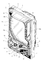
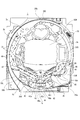
図1は実施の形態のパチンコ遊技機1の外観を示す正面側の斜視図であり、図2は遊技盤の正面図である。
図1,図2に示すパチンコ遊技機1は、主に「枠部」と「遊技盤部」から成る。
「枠部」は以下説明する前枠2,外枠2、ガラス扉5、操作パネル7を有して構成される。「遊技盤部」は図2の遊技盤3から成る。以下の説明上で、「枠部」「枠側」とは前枠2,外枠2、ガラス扉5、操作パネル7の総称とする。また「盤部」「盤側」とは遊技盤3を示す。
<1. Pachinko machine structure>
First, with reference to FIG. 1 and FIG. 2, the structure of the
FIG. 1 is a front perspective view showing the appearance of a
The
The “frame portion” includes a
図1に示すようにパチンコ遊技機1は、木製の外枠4の前面に額縁状の前枠2が開閉可能に取り付けられている。図示していないが、この前枠2の裏面には遊技盤収納フレームが形成されており、その遊技盤収納フレーム内に図2に示す遊技盤3が装着される。これにより遊技盤3の表面に形成した遊技領域3aが前枠2の開口部2aから図1の遊技機前面側に臨む状態となる。
なお遊技領域3aの前側には、透明ガラスを支持したガラス扉5が設けられており、遊技領域3aは透明ガラスを介して前面の遊技者側に表出される。
As shown in FIG. 1, the
A
ガラス扉5は軸支機構6により前枠2に対して開閉可能に取り付けられている。そしてガラス扉5の所定位置に設けられた図示しない扉ロック解除用キーシリンダを操作することで、前枠2に対するガラス扉5のロック状態を解除し、ガラス扉5を前側に開放できる構造とされている。また扉ロック解除用キーシリンダの操作によっては、外枠4に対する前枠2のロック状態も解除可能な構成とされている。
またガラス扉5の前面側には、枠側の発光手段として装飾ランプ20wが各所に設けられている。装飾ランプ20wは、例えばLEDによる発光動作として、演出用の発光動作、エラー告知用の発光動作、動作状態に応じた発光動作などを行う。
The
On the front side of the
ガラス扉5の下側には操作パネル7が設けられている。この操作パネル7も、図示しない軸支機構により、前枠2に対して開閉可能とされている。
操作パネル7には、上受け皿ユニット8、下受け皿ユニット9、発射操作ハンドル10が設けられている。
An
The
上受け皿ユニット8には、弾球に供される遊技球を貯留する上受け皿8aが形成されている。下受け皿ユニット9には、上受け皿8aに貯留しきれない遊技球を貯留する下受け皿9aが形成されている。
また上受け皿ユニット8には、上受け皿8aに貯留された遊技球を下受け皿9a側に抜くための球抜きボタン16が設けられている。下受け皿ユニット9には、下受け皿9aに貯留された遊技球を遊技機下方に抜くための球抜きレバー17が設けられている。
また上受け皿ユニット8には、図示しない遊技球貸出装置に対して遊技球の払い出しを要求するための球貸しボタン14と、遊技球貸出装置に挿入した有価価値媒体の返却を要求するためのカード返却ボタン15とが設けられている。
さらに上受け皿ユニット8には、パトライトスイッチ11(パトライトは登録商標)、演出ボタン12、十字キー13が設けられている。パトライトスイッチ11や演出ボタン12は、所定の入力受付期間中に内蔵ランプが点灯されて操作可能となり、その内蔵ランプ点灯時に押下することにより演出に変化をもたらすことができる押しボタンとされる。また十字キー13は遊技者が演出状況に応じた操作や演出設定等のための操作を行う操作子である。
The
The
Further, the
Further, the
発射操作ハンドル10は操作パネル7の右端部側に設けられ、遊技者が弾球のために図3に示す発射装置32を作動させる操作子である。
また前枠2の上部の両側と、発射操作ハンドル10の近傍には、演出音を音響出力するスピーカ25が設けられている。
The firing operation handle 10 is provided on the right end side of the
In addition,
次に図2を参照して、遊技盤3の構成について説明する。遊技盤3は、略正方形状の木製合板または樹脂板を主体として構成されている。この遊技盤3には、発射された遊技球を案内する球誘導レール31が盤面区画部材として環状に装着されており、この球誘導レール31に取り囲まれた略円形状の領域が遊技領域3aとなっている。
Next, the configuration of the
この遊技領域3aの略中央部には、主液晶表示装置32M(LCD:Liquid Crystal Display)が設けられ、また主液晶表示装置32Mの右側には副液晶表示装置32Sが設けられている。
主液晶表示装置32Mでは、後述する演出制御部51の制御の下、背景画像上で、たとえば左、中、右の3つの装飾図柄の変動表示が行われる。また通常演出、リーチ演出、スーパーリーチ演出などの各種の演出画像の表示も行われる。副液晶表示装置32Sも、同様に各種演出に応じた表示が行われる。
A main liquid
In the main liquid
また遊技領域3a内には、主液晶表示装置32M及び副液晶表示装置32Sの表示面の周囲を囲むように、センター飾り35Cが設けられている。
センター飾り35Cは、そのデザインにより装飾効果を発揮するだけでなく、周囲の遊技球から主液晶表示装置32M及び副液晶表示装置32Sの表示面を保護する作用を持つ。さらにセンター飾り35Cは、遊技球の打ち出しの強さまたはストローク長による遊技球の流路の左右打ち分けを可能とする部材としても機能する。即ち球誘導レール31を介して遊技領域3a上部に打ち出された遊技球の流下経路は、センター飾り35Cによって分割された左遊技領域3bと右遊技領域3cのいずれかを流下することとなる。いわゆる左打ちの場合、遊技球は左遊技領域3bを流下していき、右打ちの場合、遊技球は右遊技領域3cを流下していく。
A
The
また左遊技領域3bの下方には、左下飾り35Lが設けられ、装飾効果を発揮するとともに左遊技領域3bとしての範囲を規定する。
同様に右遊技領域3cの下方には右下飾り35Rが設けられ、装飾効果を発揮するとともに左遊技領域3bとしての範囲を規定する。
なお、遊技領域3a(左遊技領域3b及び右遊技領域3c)内には、所要各所に釘49や風車47が設けられて遊技球の多様な流下経路を形成する。
また主液晶表示装置32Mの下方にはセンターステージ35Sが設けられており、装飾効果を発揮するとともに、遊技球の遊動領域として機能する。
なお図示していないが、センター飾り35Cには、適所に視覚的演出効果を奏する可動体役物が設けられている。
In addition, a lower
Similarly, a lower
In the
Further, a
Although not shown in the drawing, the
遊技領域3aの右上縁付近には、複数個のLEDを配置して形成されたドット表示器による図柄表示部33が設けられている。
この図柄表示部33では、所定のドット領域により、第1特別図柄表示部、第2特別図柄表示部、及び普通図柄表示部が形成され、第1特別図柄、第2特別図柄、及び普通図柄のそれぞれの変動表示動作(変動開始および変動停止を一セットする変動表示動作)が行われる。
なお、上述した主液晶表示装置32Mは、図柄表示部33による第1、第2特別図柄の変動表示と時間的に同調して、画像による装飾図柄を変動表示する。
In the vicinity of the upper right edge of the
In the
The main liquid
センター飾り35Cの下方には、上始動口41(第1の特別図柄始動口)を有する入賞装置が設けられ、さらにその下方には下始動口42a(第2の特別図柄始動口)を備える普通変動入賞装置42が設けられている。
上始動口41及び下始動口42aの内部には、遊技球の通過を検出する検出センサ(図3に示す上始動口センサ71,下始動口センサ72)が形成されている。
A winning device having an upper start port 41 (first special symbol start port) is provided below the
Inside the upper start opening 41 and the lower start opening 42a, detection sensors (upper
上始動口41は、図柄表示部33における第1特別図柄の変動表示動作の始動条件に係る入賞口で、始動口開閉手段(始動口を開放または拡大可能にする手段)を有しない入賞率固定型の入賞装置となっている。
The
下始動口42aを有する普通変動入賞装置42は、始動口開閉手段により始動口の遊技球の入賞率を変動可能な入賞率変動型の入賞装置として構成されている。即ち下始動口42aを開放または拡大可能にする左右一対の可動翼片(可動部材)42bを備えた、いわゆる電動チューリップ型の入賞装置である。
この普通変動入賞装置42の下始動口42aは、図柄表示部33における第2特別図柄の変動表示動作の始動条件に係る入賞口である。そして、この下始動口42aの入賞率は可動翼片42bの作動状態に応じて変動する。即ち可動翼片42bが開いた状態では、入賞が容易となり、可動翼片42bが閉じた状態では、入賞が困難又は不可能となるように構成されている。
The normal
The lower start opening 42 a of the normal
また普通変動入賞装置42の左右には、一般入賞口43が複数個設けられている。各一般入賞口42の内部には、遊技球の通過を検出する検出センサ(図3に示す一般入賞口センサ74)が形成されている。
また右遊技領域3cの下部側には、遊技球が通過可能なゲート(特定通過領域)からなる普通図柄始動口44が設けられている。この普通図柄始動口44は、図柄表示部33における普通図柄の変動表示動作に係る入賞口であり、その内部には、通過する遊技球を検出するセンサ(図3に示すゲートセンサ73)が形成されている。
In addition, a plurality of general winning
In addition, a normal
右遊技領域3c内の普通図柄始動口44から普通変動入賞装置42へかけての流下経路途中には第1特別変動入賞装置45(特別電動役物)が設けられている。
第1特別変動入賞装置45は、突没式の開放扉45bにより第1大入賞口45aを閉鎖/開放する構造とされている。また、その内部には第1大入賞口45aへの遊技球の通過を検出するセンサ(図3の第1大入賞口センサ75)が形成されている。
第1大入賞口45aの周囲は、右下飾り35Rが遊技盤3の表面から膨出した状態となっており、その膨出部分の上辺及び開放扉45bの上面が右流下経路3cの下流案内部を形成している。従って、開放扉45bが盤内部側に引き込まれることで、下流案内部に達した遊技球は容易に第1大入賞口45に入る状態となる。
A first special variable winning device 45 (special electric accessory) is provided along the flow path from the normal
The first special variable winning
The lower
また普通変動入賞装置42の下方には、第2特別変動入賞装置46(特別電動役物)が設けられている。第2特別変動入賞装置46は、下部が軸支されて開閉可能な開放扉46bにより、その内側の第2大入賞口46aを閉鎖/開放する構造とされている。また、その内部には第2大入賞口46aへの遊技球の通過を検出するセンサ(図3の第2大入賞口センサ76)が形成されている。
開放扉46bが開かれることで第2大入賞口46aが開放される。この状態では、左遊技領域3b或いは右遊技領域3cを流下してきた遊技球は、高い確率で第2大入賞口50に入ることとなる。
A second special variable winning device 46 (special electric accessory) is provided below the normal
The second
以上のように盤面の遊技領域には、入賞口として上始動口41、下始動口42a、普通図柄始動口44、第1大入賞口45a、第2大入賞口46a、一般入賞口43が形成されている。
本実施の形態のパチンコ遊技機1においては、これら入賞口のうち、普通図柄始動口44以外の入賞口への入賞があった場合には、各入賞口別に設定された入賞球1個当りの賞球数が遊技球払出装置55(図3参照)から払い出される。
例えば、上始動口41および下始動口42aは3個、第1大入賞口45a、第2大入賞口46aは13個、一般入賞口43は10個などと賞球数が設定されている。
なお、これらの各入賞口に入賞しなかった遊技球は、アウト口48を介して遊技領域3aから排出される。
ここで「入賞」とは、入賞口がその内部に遊技球を取り込んだり、ゲートを遊技球が通過したりすることをいう。実際には入賞口ごとに形成されたセンサ(各入賞検出スイッチ)により遊技球が検出された場合、その入賞口に「入賞」が発生したものとして扱われる。この入賞に係る遊技球を「入賞球」とも称する。
As described above, the
In the
For example, the upper start opening 41 and the lower start opening 42a are set to three, the first big winning
Note that the game balls that have not won the prize holes are discharged from the
Here, “winning” means that the winning opening takes the game ball inside, or the game ball passes through the gate. Actually, when a game ball is detected by a sensor (each winning detection switch) formed for each winning opening, it is treated that a “winning” has occurred in that winning opening. The game ball related to the winning is also referred to as “winning ball”.
以上のような盤面において、センター飾り35C、左下飾り35L、右下飾り35R、センターステージ35S、第1特別変動入賞装置45、第2特別変動入賞装置46、さらには図示していない可動体役物には、詳細には図示していないが各所に、盤側の発光手段として装飾ランプ20bが設けられている。
装飾ランプ20bは、例えばLEDによる発光動作として、演出用の発光動作、エラー告知用の発光動作、動作状態に応じた発光動作などを行う。
On the board as described above, the
The
<2.パチンコ遊技機の制御構成及び実施の形態のドライバ構成>
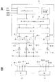
次に本実施の形態のパチンコ遊技機1の制御系の構成について説明する。図3はパチンコ遊技機1の内部構成の概略的なブロック図である。
本実施の形態のパチンコ遊技機1は、その制御構成を形成する基板として主に、主制御基板50、演出制御基板51、液晶制御基板52、払出制御基板53、発射制御基板54、電源基板58が設けられている。
<2. Control configuration of pachinko gaming machine and driver configuration of embodiment>
Next, the configuration of the control system of the
The
主制御基板50は、マイクロコンピュータ等が搭載され、パチンコ遊技機1の遊技動作全般に係る統括的な制御を行う。なお以下では、主制御基板50に搭載されたマイクロコンピュータ等を含めて主制御基板50の構成体を「主制御部50」と表記する。
演出制御基板51は、マイクロコンピュータ等が搭載され、主制御部50から演出制御コマンドを受けて、画像表示、発光、音響出力を用いた各種の演出動作を実行させるための制御を行う。なお以下では、演出制御基板51に搭載されたマイクロコンピュータ等を含めて演出制御基板51の構成体を「演出制御部51」と表記する。
The
The
液晶制御基板52はマイクロコンピュータやビデオプロセッサ等が搭載され、演出制御部51からの表示制御コマンドを受けて、主液晶表示装置32M、副液晶表示装置32Sによる表示動作の制御を行う。
なお主液晶表示装置32M、副液晶表示装置32Sによる表示動作の制御を行う液晶制御基板として、主液晶制御基板、副液晶制御基板を独立して設けてもよい。
払出制御基板53は、パチンコ遊技機1に接続された遊技球払出装置55による賞球の払い出し制御を行う。
発射制御基板54は、遊技者のパチンコ遊技機1に設けられている発射装置56による遊技球の発射動作の制御を行う。
電源基板58は、外部電源(例えばAC24V)からAC/DC変換、さらにはDC/DC変換を行い、各部に動作電源電圧Vccを供給する。なお電源経路の図示は省略している。
The liquid
Note that the main liquid crystal control substrate and the sub liquid crystal control substrate may be provided independently as the liquid crystal control substrate for controlling the display operation by the main liquid
The
The
The
まず主制御部50及びその周辺回路について述べる。
主制御部50は、CPU100(以下「主制御CPU100」と表記)を内蔵したマイクロプロセッサ、ROM101(以下「主制御ROM101」と表記)、RAM102(以下「主制御RAM102」と表記)を搭載し、マイクロコンピュータを構成している。
主制御CPU100は制御プログラムに基づいて、遊技の進行に応じた各種演算及び制御処理を実行する。
主制御ROM101は、主制御CPU100による遊技動作の制御プログラムや、遊技動作制御に必要な種々のデータを記憶する。
主制御RAM102は、主制御CPU100が各種演算処理に使用するワークエリアや、各種入出力データや処理データのバッファ領域として用いられる。
なお図示は省略したが、主制御部50は、各部とのインターフェース回路、特別図柄変動表示に係る抽選用乱数を生成する乱数生成回路、各種の時間計数のためのCTC(Counter Timer Circuit)、主制御CPU100に割込み信号を与える割込コントローラ回路なども備えている。
First, the
The
The
The
The
Although not shown, the
主制御部50は、上述のように盤面の遊技領域の各入賞手段(上始動口41、下始動口42a、普通図柄始動口44、第1大入賞口45a、第2大入賞口46a、一般入賞口43)に設けられるセンサの検出信号を受信する構成となっている。
即ち、上始動口センサ71、下始動口センサ72、ゲートセンサ73、一般入賞口センサ74、第1大入賞口センサ75、第2大入賞口センサ76のそれぞれの検出信号が主制御部50に供給される。
なお、これらのセンサ(71〜76)は、入球した遊技球を検出する検出スイッチにより構成されるが、具体的にはフォトスイッチや近接スイッチなどの無接点スイッチや、マイクロスイッチなどの有接点スイッチで構成することができる。
As described above, the
That is, the detection signals of the upper
These sensors (71 to 76) are configured by detection switches that detect a game ball that has entered, but specifically, contactless switches such as photoswitches and proximity switches, and contact points such as microswitches. It can consist of switches.
主制御部50は、上始動口センサ71、下始動口センサ72、ゲートセンサ73、一般入賞口センサ74、第1大入賞口センサ75、第2大入賞口センサ76のそれぞれの検出信号の受信に応じて、処理を行う。例えば抽選処理、図柄変動制御、賞球払出制御、演出制御コマンド送信制御、外部データ送信処理などを行う。
The
また主制御部50には、下始動口42の可動翼片42bを開閉駆動する普通電動役物ソレノイド77が接続され、主制御部50は遊技進行状況に応じて制御信号を送信して普通電動役物ソレノイド77の駆動動作を実行させ、可動翼片42bの開閉動作を実行させる。
さらに、主制御部50には、第1大入賞口45の開放扉45bを開閉駆動する第1大入賞口ソレノイド78と、第2大入賞口46の開放扉46bを開閉駆動する第2大入賞口ソレノイド79が接続されている。主制御部50は、いわゆる大当たり状況に応じて、第1大入賞口ソレノイド78又は第2大入賞口ソレノイド79を駆動制御して、第1大入賞口45又は第2大入賞口46の開放動作を実行させる。
The
Further, the
また主制御部50には、図柄表示部33が接続されており、図柄表示部33に制御信号を送信して、各種図柄表示(LEDの消灯/点灯/点滅)を実行させる。これにより図柄表示部33における第1特別図柄表示部80、第2特別図柄表示部81、普通図柄表示部82での表示動作が実行される。
In addition, a
また主制御部50には、枠用外部端子基板57が接続される。主制御部50は、遊技進行に関する情報を、枠用外部端子基板57を介して図示しないホールコンピュータに送信可能となっている。遊技進行に関する情報とは、例えば大当り当選情報、賞球数情報、図柄変動表示実行回数情報などの情報である。ホールコンピュータとは、パチンコホールの遊技機を統括的に管理する管理コンピュータであり、遊技機外部に設置されている。
The
また主制御部50には、払出制御基板53が接続されている。払出制御基板53には、発射装置56を制御する発射制御基板54と、遊技球の払い出しを行う遊技球払出装置55が接続されている。
主制御部50は、払出制御基板53に対し、払い出しに関する制御コマンド(賞球数を指定する払出制御コマンド)を送信する。払出制御基板53は当該制御コマンドに応じて遊技球払出装置55を制御し、遊技球の払い出しを実行させる。
また払出制御基板53は、主制御部50に対して、払い出し動作状態に関する情報(払出状態信号)を送信可能となっている。主制御部50側では、この払出状態信号によって、遊技球払出装置55が正常に機能しているか否かを監視する。具体的には、賞球の払い出し動作の際に、玉詰まりや賞球の払い出し不足といった不具合が発生したか否かを監視している。
In addition, a
The
The
また主制御部50は、特別図柄変動表示に関する情報を含む演出制御コマンドを、演出制御部51に送信する。なお、主制御部50から演出制御部51への演出制御コマンドの送信は一方向通信により実行されるようにしている。これは、外部からの不正行為による不正な信号が演出制御部51を介して主制御部50に入力されることを防止するためである。
The
続いて演出制御部51及びその周辺回路について説明する。
演出制御部51は、CPU200(以下「演出制御CPU200」と表記)を内蔵したマイクロプロセッサ、ROM201(以下「演出制御ROM201」と表記)、RAM202(以下「演出制御RAM202」と表記)を搭載し、マイクロコンピュータを構成している。
演出制御CPU200は演出制御プログラム及び主制御部50から受信した演出制御コマンドに基づいて、各種演出動作のための演算処理や各演出手段の制御を行う。演出手段とは、本実施の形態のパチンコ遊技機1の場合、主液晶表示装置32M、副液晶表示装置32S、装飾ランプ20w、20b、スピーカ59及び図示を省略した可動体役物となる。
演出制御ROM201は、演出制御CPU200による演出動作の制御プログラムや、演出動作制御に必要な種々のデータを記憶する。
演出制御RAM202は、演出制御CPU200が各種演算処理に使用するワークエリアや、テーブルデータ領域、各種入出力データや処理データのバッファ領域などとして用いられる。
なお図示は省略したが、演出制御部51は、各部とのインターフェース回路、演出のための抽選用乱数を生成する乱数生成回路、各種の時間計数のためのCTC、演出制御CPU200に割込み信号を与える割込コントローラ回路なども備えている。
この演出制御部51の主な役割は、主制御部50からの演出制御コマンドの受信、演出制御コマンドに基づく演出の選択決定、主液晶表示装置32M、副液晶表示装置32S側への演出制御コマンドの送信、スピーカ25による出力音制御、装飾ランプ20w,20b(LED)の発光制御、可動体役物の動作制御などとなる。
Next, the
The
The
The
The
Although illustration is omitted, the
The main roles of the
演出制御部51は、主液晶表示装置32M、副液晶表示装置32S側への演出制御コマンドの送信を行うが、その演出制御コマンドは、液晶インターフェース基板66を介して液晶制御基板52に送られる。
The
液晶制御基板52は、主液晶表示装置32M及び副液晶表示装置32Sの表示制御を行う。図示していないが、液晶制御基板52には、VDP(Video Display Processor)、画像ROM、VRAM(Video RAM)、液晶制御CPU、液晶制御ROM、液晶制御RAMを備えている。
VDPは、画像展開処理や画像の描画などの映像出力処理全般の制御を行う。
画像ROMには、VDPが画像展開処理を行う画像データ(演出画像データ)が格納されている。
VRAMは、VDPが展開した画像データを一時的に記憶する画像メモリ領域とされる。
液晶制御CPUは、VDPが表示制御を行うために必要な制御データを出力する。
液晶制御ROMには、液晶制御CPUの表示制御動作手順を記述したプログラムやその表示制御に必要な種々のデータが格納される。
液晶制御RAMは、ワークエリアやバッファメモリとして機能する。
The liquid
The VDP performs overall control of video output processing such as image development processing and image drawing.
The image ROM stores image data (effect image data) on which the VDP performs image expansion processing.
The VRAM is an image memory area that temporarily stores image data developed by the VDP.
The liquid crystal control CPU outputs control data necessary for the VDP to perform display control.
The liquid crystal control ROM stores a program describing the display control operation procedure of the liquid crystal control CPU and various data necessary for the display control.
The liquid crystal control RAM functions as a work area and a buffer memory.
液晶制御基板52は、これらの構成により、演出制御基板51からの演出制御コマンドに基づいて各種の画像データを生成し、主液晶表示装置32M及び副液晶表示装置32Sに出力する。これによって主液晶表示装置32M及び副液晶表示装置32Sにおいて各種の演出画像が表示される。
With these configurations, the liquid
また演出制御部51は、光演出や音演出の制御を行う。このため演出制御部51には枠ドライバ部61、盤ドライバ部62及び音源IC(Integrated Circuit)59が接続されている。
枠ドライバ部61は、枠側の装飾ランプ部63のLEDについて発光駆動を行う。なお、装飾ランプ部63とは、図1に示したように枠側に設けられている装飾ランプ20wを総括的に示したものである。
盤ドライバ部62は、盤側の装飾ランプ部64のLEDについて発光駆動を行う。なお、装飾ランプ部64とは、図2に示したように盤側に設けられている装飾ランプ20bを総括的に示したものである。また本実施の形態の場合、盤ドライバ部62は、盤側に形成されている可動体役物を駆動する可動体役物モータ65の駆動も行う。可動体役物モータ65は例えばステッピングモータが用いられる。
The
The
The
本実施の形態の場合、枠ドライバ部61は第1系統の駆動信号出力手段であり、盤ドライバ部62は第2系統の駆動信号出力手段である。詳しくは図4を用いて後述するが、演出制御部51(演出制御CPU200)は、シリアルデータ送信チャネルch1,ch2を用いて、演出駆動データをシリアルデータとして第1系統及び第2系統の駆動信号出力手段(枠ドライバ部61及び盤ドライバ部62)に供給する。
なおこの例では盤ドライバ部62は、盤側に形成されている可動体役物を駆動する可動体役物モータ65の駆動も行うものとしているが、装飾ランプ部64の各LEDを発光駆動するドライバ部と、可動体役物モータ65を駆動するドライバ部が別体として設けられても良い。
In the case of the present embodiment, the
In this example, the
また演出制御部51は、スピーカ25により所望の音を出力させるべく、音源IC59に対する制御を行う。音源IC59には音データROM69が接続されており、音源IC59は音データROM69から必要な音データ(再生するフレーズの音データ)を取得して音声信号出力を行う。
音源IC59は、複数チャネル(後述する音チャネルaCH)のフレーズをミキシングして所定本数(チャネル数)の音声信号を得る。図1に示したように、本例の場合、スピーカ25は複数設けられるため、音源IC59の出力チャネル数は例えばLch,Rchの2チャネルなど(ステレオ出力)が可能となる。上記のミキシングにより、演出制御部51より再生指示された複数チャネルのフレーズを同時再生可能とされる。
また音源IC59は、演出制御部51からの指示に従い、制御対象として指示されたフレーズについての音コントロールを行う。具体的に、演出制御部51は、ボリュームの変化指示やフェードイン再生/フェードアウト再生等の音響効果の付与指示に係る情報を音源IC59に対して与え、音源IC59はそれらの情報に従って制御対象として指定されたフレーズの再生制御を行う。
Further, the
The
The
本実施の形態で用いる音源IC59は、SUBボリュームの設定機能やパン機能(左右方向パン及び上下方向パン)も有するものとされる。
この場合の音源IC59が音出力を行うにあたって指示を要求する情報は、少なくとも「フレーズ番号」「1次ボリューム」「1次ボリューム遷移量」「2次ボリューム」「ループ回数」「SUB0ボリューム」「SUB1ボリューム」「左右パンポット」「左右パンポット遷移量」「上下パンポット」「上下パンポット遷移量」とされる。すなわち、この場合の音源IC59には、これらの項目ごとにその指示値の入力を受け付けるレジスタが音チャネルaCHごとに設けられている。
なお、本実施の形態ではSUBボリュームは使用しないものとしている。従って上記の「SUB0ボリューム」「SUB1ボリューム」のレジスタには「0」をセットする(後述する図31のステップS1202を参照)。
The
In this case, the
In the present embodiment, the SUB volume is not used. Accordingly, “0” is set in the registers of the “SUB0 volume” and “SUB1 volume” (see step S1202 in FIG. 31 described later).
音源IC59による出力音声信号はアンプ部67で増幅された後、スピーカ25に対して与えられる。
なお、図3では図示の都合上、音源IC59の出力チャネル数を1つとしているが、実際にはアンプ部67及びスピーカ25は例えばLch、Rchに対応した出力チャネルがそれぞれ設けられ、ステレオによる音再生が可能とされる。
The output audio signal from the
In FIG. 3, for convenience of illustration, the number of output channels of the
なお、上記では音源IC59を演出制御基板51とは別体に設けるものとしたが、音源IC59は演出制御基板51と同一基板上に一体的に設けることもできる。
In the above description, the
また演出制御部51には、遊技者が操作可能な操作部60が接続され、操作部60からの操作検出信号を受信可能となっている。この操作部60は、図1で説明したパトライトスイッチ11、演出ボタン12、十字キー13と、それらの操作検出機構のことである。
演出制御部51は、操作部60からの操作検出信号に応じて、各種演出制御を行うことができる。
The
The
演出制御部51は、主制御部50から送られてくる演出制御コマンドに基づき、あらかじめ用意された複数種類の演出パターンの中から抽選によりあるいは一意に演出パターンを決定し、必要なタイミングで各種演出手段を制御する。これにより、演出パターンに対応する主・副液晶表示装置32M、32Sによる演出画像の表示、スピーカ25からの音再生、装飾ランプ部63、64(装飾ランプ20w、20b)におけるLEDの点灯点滅駆動、可動体役物モータ65による可動体役物の動作が実現され、時系列的に種々の演出パターンが展開されていく。これにより「演出シナリオ」が実現される。
The
なお演出制御コマンドは、1バイト長のモード(MODE)と、同じく1バイト長のイベント(EVENT)からなる2バイト構成により機能を定義する。
MODEとEVENTの区別を行うために、MODEのBit7はON、EVENTのBit7をOFFとしている。
これらの情報を有効なものとして送信する場合、モード(MODE)およびイベント(EVENT)各々に対応してストローブ信号が出力される。すなわち、主制御CPU100は、送信すべきコマンドがある場合、演出制御部51にコマンドを送信するためのモード(MODE)情報の設定および出力を行い、この設定から所定時間経過後に1回目のストローブ信号の送信を行う。さらに、このストローブ信号の送信から所定時間経過後にイベント(EVENT)情報の設定および出力を行い、この設定から所定時間経過後に2回目のストローブ信号の送信を行う。
ストローブ信号は主制御CPU100により、演出制御CPU200が確実にコマンドを受信することが可能な所定期間アクティブ状態に制御される。
また演出制御部51(演出制御CPU200)は、ストローブ信号の入力に基づいて割込を発生させてコマンド受信割込処理用の制御プログラムを実行し、この割込処理において演出制御コマンドが取得される。
The effect control command defines a function by a 2-byte structure consisting of a 1-byte length mode (MODE) and a 1-byte length event (EVENT).
In order to distinguish between MODE and EVENT,
When these pieces of information are transmitted as valid, a strobe signal is output corresponding to each of the mode (MODE) and the event (EVENT). That is, when there is a command to be transmitted, the
The strobe signal is controlled by the
The effect control unit 51 (effect control CPU 200) generates an interrupt based on the input of the strobe signal and executes a control program for command reception interrupt processing, and the effect control command is acquired in this interrupt processing. .
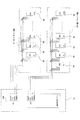
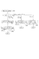
続いて、上述した第1系統及び第2系統の駆動信号出力手段(枠ドライバ部61及び盤ドライバ部62)の構成を説明する。
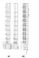
図4に、演出制御部51に接続される枠ドライバ部61、盤ドライバ部62を示した。
Then, the structure of the drive signal output means (the
FIG. 4 shows the
第1系統の駆動信号出力手段である枠ドライバ部61は、n個のLEDドライバ90が、演出制御CPU200のシリアルデータ出力チャネルch1に対して並列に接続されている。
シリアルデータ出力チャネルch1の信号線としては、リセット信号RESETを供給するリセット信号線、クロック信号CLKを供給するクロック線、演出駆動データとしてのシリアルデータDATAを供給するデータ線、イネーブル信号ENABLEを供給するイネーブル信号線が設けられている。これら各信号線は、それぞれ、枠ドライバ部61を構成するn個のLEDドライバ90に対して各信号を並列に供給するように接続されている。
枠ドライバ部61の各LEDドライバ90には、演出制御CPU200がスレーブアドレスとして用いるデバイスIDが設定されている。即ち個々のLEDドライバ90の識別子である。説明上、仮に、図示のように各LEDドライバ90のデバイスID(スレーブアドレス)をw1〜w(n)と表記する。
In the
As a signal line of the serial data output channel ch1, a reset signal line for supplying a reset signal RESET, a clock line for supplying a clock signal CLK, a data line for supplying serial data DATA as effect drive data, and an enable signal ENABLE are supplied. An enable signal line is provided. Each of these signal lines is connected so as to supply each signal in parallel to
In each
また第2系統の駆動信号出力手段である盤ドライバ部62は、m個のLEDドライバ90が、演出制御CPU200のシリアルデータ出力チャネルch2に対して並列に接続されている。
シリアルデータ出力チャネルch2の信号線もチャネルch1と同様、リセット信号RESETを供給するリセット信号線、クロック信号CLKを供給するクロック線、演出駆動データとしてのシリアルデータDATAを供給するデータ線、イネーブル信号ENABLEを供給するイネーブル信号線が設けられている。これら各信号線は、それぞれ、盤ドライバ部62を構成するm個のLEDドライバ90に対して各信号を並列に供給するように接続されている。
盤ドライバ部62の各LEDドライバ90には、演出制御CPU200がスレーブアドレスとして用いるデバイスID(個々のLEDドライバ90の識別子)が設定されている。説明上、仮に、図示のように各LEDドライバ90のデバイスID(スレーブアドレス)をb1〜b(m)と表記する。
In the
Similarly to channel ch1, the signal line of serial data output channel ch2 is a reset signal line for supplying reset signal RESET, a clock line for supplying clock signal CLK, a data line for supplying serial data DATA as effect drive data, and an enable signal ENABLE. An enable signal line for supplying is provided. Each of these signal lines is connected so as to supply each signal in parallel to m
In each
枠ドライバ部61及び盤ドライバ部62における各LEDドライバ90としては、例えば24チャネルLEDドライバである「LV5236V(三洋半導体株式会社製)」を用いることができ、24個の電流出力端子を備える。従って1つのLEDドライバ90によっては、最大24個の系列のLED駆動電流を出力することができる。具体的には例えば8系列のR(赤)LED駆動電流出力、8系列のG(緑)LED駆動電流出力、8系列のB(青)LED駆動電流出力を行い、8個のフルカラーLEDの発光駆動が可能である。なお、ここでは1つの「系列」とは、1つの電流出力端子に対して接続される1つのLED、又は1つの電流出力端子に対して直列又は並列で接続される複数個のLEDの群を指している。
枠ドライバ部61におけるLEDドライバ90の数nは、枠側に配置されるLED系列数(装飾ランプ20wの系列数)によって決められる。従ってnは1の場合もあるし、2以上の場合もある。枠ドライバ部61は1又は複数のLEDドライバ90を有する。
また盤ドライバ部62におけるLEDドライバ90の数mは、盤側に配置されるLED系列数(装飾ランプ20bの系列数)によって決められる。従ってmは1の場合もあるし、2以上の場合もある。盤ドライバ部62は1又は複数のLEDドライバ90を有する。
As each
The number n of
Further, the number m of
図5AにLEDドライバ90の要部の概略構成例を示す。
LEDドライバ90は、シリアルバスインターフェース91、アドレス設定部92、データバッファ/PWMコントローラ93、D/A変換器94、駆動電流源回路95−1〜95−24を備える。
駆動電流源回路95−1〜95−24は、上記の24系列の駆動電流出力を、それぞれ出力端子96−1〜96−24から行う電流源である
FIG. 5A shows a schematic configuration example of a main part of the
The
The drive current source circuits 95-1 to 95-24 are current sources that perform the 24 series drive current outputs from the output terminals 96-1 to 96-24, respectively.
このLEDドライバ90には、シリアルバスインターフェース91に対し、演出制御CPU200からのイネーブル信号ENABLE、クロック信号CLK、シリアルデータDATAが入力される。シリアルバスインターフェース91は、イネーブル信号ENABLEで規定される期間に、クロック信号CLKのタイミングでシリアルデータDATAを取り込む。シリアルバスインターフェース91は、取り込んだシリアルデータをパラレルデータに変換してデータバッファ/PWMコントローラ93に転送する。
なお演出制御CPU200はスレーブアドレスを指定してLED駆動データを送信してくる。
データバッファ/PWMコントローラ93は、シリアルバスインターフェース91から転送されたパラレルデータについて、スレーブアドレス確認を行う。パラレルデータに含まれるスレーブアドレスが、アドレス設定部92に設定された自己のスレーブアドレス(w1〜w(n)、b1〜b(m)のいずれか)と一致していることを確認した場合に、該パラレルデータに含まれるLED駆動データを有効なデータとして、指定されたレジスタに格納する。
The
The
The data buffer /
データバッファ/PWMコントローラ93は、各系列のLED駆動データを取り込んだら、そのLED駆動データで示された輝度情報(階調値)に応じた値を、24系列の各駆動制御値としてD/A変換器94に出力する。
D/A変換器94は、輝度情報に応じた値をアナログ信号に変換し、各電流源回路95−1〜95−24への制御信号とする。
When the data buffer /
The D /
出力端子96−1〜96−24の全部(又は一部)には24系列のLED120が接続される。なお、図は簡略化して1系列の出力端子96に1つのLED120が接続された状態を示しているが、1系列の出力端子96に、複数のLEDが接続される構成(例えば直列接続)も当然あり得る。
各系列(出力端子96−1〜96−24)では、LED120及び抵抗Rの直列接続に対して電源電圧Vccが印加される。電流源回路95−1〜95−24によって各系列のLED120に電流が流され、発光が行われる。
即ち各電流源回路95−1〜95−24は、D/A変換器94から供給された信号に応じた電流量の駆動電流を、対応する系列のLED120に流すように動作する。
24 series of
In each series (output terminals 96-1 to 96-24), the power supply voltage Vcc is applied to the series connection of the
That is, each of the current source circuits 95-1 to 95-24 operates so that a drive current having a current amount corresponding to the signal supplied from the D /
このようなLED駆動制御を、1つの系列について具体的にいうと、データバッファ/PWMコントローラ93は、当該系列の階調値に応じたパルスデューティに相当するデジタルデータ列をD/A変換器94に出力し、D/A変換器94は、デジタルデータ列をアナログ信号としてのパルス信号に変換して当該系列の電流源回路95に供給する。電流源回路95はパルス信号のH/Lにより出力制御され、例えば0mAと5mAの電流出力を行う。例えばこのような動作で、結果的に階調値に応じた平均電流値となる駆動電流がLED120に流れることとなる。
なお、本実施の形態では、PWM駆動方式により、電流値が例えば0mAと5mAとされ、時間軸方向で(積分的に)階調制御がされるものとしているが、もちろん階調制御はこれに限らず、実際に電流値を階調に応じて変化させても良いことはいうまでもいない。デューティ制御であろうと、レベル制御であろうと、あくまでも単位時間あたりの平均電流値が階調に応じたレベルとされることで適切な階調表現が可能となる。
Specifically, such LED drive control is described for one series. The data buffer /
In this embodiment, the current value is set to, for example, 0 mA and 5 mA by the PWM driving method, and gradation control is performed (integrally) in the time axis direction. Needless to say, the current value may actually be changed according to the gradation. Regardless of duty control or level control, appropriate gradation expression can be realized by setting the average current value per unit time to a level corresponding to the gradation.
なお、本実施の形態の場合、盤ドライバ部62における一部のLEDドライバ90には、可動体役物を駆動する可動体役物モータ65が接続される。図5Bに、或るLEDドライバ90の出力端子96−1〜96−24の全部(又は一部)に例えばステッピングモータ121が接続された例を示している。図5Bは出力端子96−1〜96−24の部分のみを示しているが、LEDドライバ90の内部構成は図5Aと同様である。
例えばステッピングモータ121が4相駆動のモータである場合、出力端子96−1〜96−4で1つのステッピングモータ121に対する励磁電流を流すように接続する。同様に、出力端子96−5〜96−8、出力端子96−9〜96−12、出力端子96−13〜96−16、出力端子96−17〜96−20、出力端子96−21〜96−24が、それぞれ1つのステッピングモータ121に励磁電流を流すように接続される。この場合、1つのLEDドライバ90で最大6個のステッピングモータ121を駆動できることとなる。
LEDドライバ90は与えられたコマンド(シリアルデータ)によって指示される電流を出力端子96−1〜96−24から出力する回路であることから、ステッピングモータやソレノイド等の物理的可動体駆動デバイスのドライバとしても使用することができる。そこで、一部のLEDドライバ90を図5Bのようにステッピングモータ121のドライバとして用いる。可動体役物の動作は演出シナリオによって細かく設定され、それに応じて演出制御部51は駆動方向や駆動量などを制御するわけであるが、盤ドライバ部62におけるLEDドライバ90を利用して可動体役物を駆動することで、装飾ランプ部64の各装飾ランプ(LED20b)とともにシリアルデータによる可動体役物制御が可能となり、制御処理及び構成が効率化できる。
なお、1つのLEDドライバ90において、一部の出力端子がLED駆動に用いられ、他の一部の出力端子がステッピングモータやソレノイド等の駆動に用いられるという手法を採っても良い。
In the case of the present embodiment, a movable
For example, when the stepping
The
In one
以上のように、各LEDドライバ90は、演出制御CPU200から受信したシリアルデータDATAに応じて、指定された輝度で各LED120が発光されるように駆動することとなる。或いはLEDドライバ90の一部は、シリアルデータDATAに応じて、ステッピングモータ121を駆動する。
そして第1系統、第2系統の駆動信号出力手段(枠ドライバ部61、盤ドライバ部62)には、それぞれが1又は複数の演出手段に駆動信号を出力する複数のLEDドライバ90が含まれ、1つの系統内の各LEDドライバ90には、演出制御部51からのシリアルデータが、並列に送信される構成とされている。そして各LEDドライバ90は、自己のID(スレーブアドレス)が含まれる演出駆動データ(シリアルデータ)を取得する。
As described above, each
Each of the first and second system drive signal output means (
<3.主制御部の処理>
以下、本実施の形態の制御処理につき説明する。まずここでは主制御部(主制御基板)50によるメイン処理について述べる。
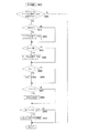
図6は、主制御部50のメイン処理を示すフローチャートである。メイン処理が開始されるのは、停電状態からの復旧時のように初期化スイッチ(図示せず)が操作されることなく電源がON状態になる場合と、初期化スイッチがON操作されて電源がON状態になる場合とがある。いずれの場合でも、パチンコ遊技機1に電源が投入されると、電源基板58によって各制御基板に電圧が供給される。この場合に主制御部50(主制御CPU100)は図6に示すメイン処理を開始する。
<3. Processing of main control unit>
Hereinafter, control processing according to the present embodiment will be described. First, main processing by the main control unit (main control board) 50 will be described here.
FIG. 6 is a flowchart showing main processing of the
この主制御側メイン処理において、主制御CPU100はステップS11で、まず遊技動作開始前における必要な初期設定処理を実行する。たとえば、最初に自らを割込み禁止状態に設定すると共に、所定の割込みモード(割込みモード2)に設定し、またマイクロコンピュータの各部を含めてCPU内部のレジスタ値を初期設定する。
次に主制御CPU100はステップS12で、図示してない入力ポートを介して入力されるRAMクリアスイッチの出力信号であるRAMクリア信号の状態(ON、OFF)を判定する。RAMクリア信号とは、RAMの全領域を初期設定するか否かを決定する信号である。RAMクリア信号としては通常、パチンコ店の店員が操作する初期化スイッチのON/OFF状態に対応した値を有している。
In the main control side main process, the
Next, in step S12, the
RAMクリア信号がON状態であった場合、主制御CPU100は処理をステップS12からS16に進め、RAMの全領域のゼロクリアを行う。したがって、電源遮断時にセットされたバックアップフラグの値は、他のチェックサム値などと共にゼロとなる。
続いてステップS17で主制御CPU100は、RAM領域がゼロクリアされたことを報知するための「RAMクリア表示コマンド」を初期化コマンドとして各制御基板に送信する。そしてステップS18で、RAMクリア報知タイマに、RAMクリアされた旨を報知するための時間として、たとえば、30秒を格納する。
When the RAM clear signal is in the ON state, the
Subsequently, in step S17, the
次に主制御CPU100はステップS19で、タイマ割込み動作を起動する割込み信号を出力するCTCを初期設定して、CPUを割込み許可状態に設定する。
その後はステップS20、S21、S22の処理として、割込みが発生するまで割込禁止状態と割込許可状態とを繰り返すとともに、その間に、各種乱数更新処理を実行する。このステップS21の各種乱数更新処理では、特別図柄変動表示や普通図柄変動表示に使用される各種乱数の初期値(スタート値)変更のために使用する乱数や、変動パターンの選択に利用される変動パターン用乱数を更新する。
なお、特別図柄変動表示や普通図柄変動表示に使用される各種乱数とは、例えばインクリメント処理によって所定数値範囲を循環している大当り抽選に係る乱数(図柄抽選に利用される特別図柄判定用乱数)や、補助当り抽選に係る乱数(補助当りの当落抽選に利用される補助当り判定用乱数)などである。また初期値変更のために使用する乱数とは、特別図柄判定用初期値乱数、補助当り判定用初期値乱数などである。
Next, in step S19, the
Thereafter, as the processing of steps S20, S21, and S22, the interrupt disabled state and the interrupt enabled state are repeated until an interrupt occurs, and various random number update processes are executed during that time. In the various random number update processing in step S21, random numbers used for changing initial values (start values) of various random numbers used for special symbol fluctuation display and normal symbol fluctuation display, and fluctuations used for selection of fluctuation patterns. Update pattern random numbers.
The various random numbers used for the special symbol variation display and the normal symbol variation display are, for example, random numbers related to jackpot lottery circulating through a predetermined numerical range by increment processing (special symbol determination random numbers used for symbol lottery). Or a random number related to a lottery per assistance (a random number for judging per assistance used in winning lottery per assistance). The random numbers used for changing the initial value include an initial value random number for special symbol determination, an initial value random number for auxiliary hit determination, and the like.
主制御RAM102には大当り抽選に係る図柄抽選、補助当り抽選、または変動パターン抽選などに利用される各種の乱数カウンタとして、特別図柄判定用乱数カウンタ初期値の生成用カウンタ、特別図柄判定用乱数カウンタ、補助当り判定用乱数カウンタ初期値の生成用カウンタ、補助当り判定用乱数カウンタ、変動パターン用乱数1カウンタ、変動パターン用乱数2カウンタなどが設けられている。これらのカウンタは、ソフトウェア的に乱数を生成する乱数生成手段としての役割を果たす。
ステップS21の各種乱数更新処理では、上述の特別図柄判定用乱数カウンタや補助当り判定用乱数カウンタの初期値を生成する2つの初期値生成用カウンタ、変動パターン用乱数1カウンタ、変動パターン用乱数2カウンタなどを更新して、上記各種のソフト乱数を生成する。たとえば、変動パターン用乱数1カウンタとして取り得る数値範囲が0〜238とすると、主制御RAM102の変動パターン用乱数1の値を生成するためのカウント値記憶領域から値を取得し、取得した値に1を加算してから元のカウント値記憶領域に格納する。このとき、取得した値に1を加算した結果が239であれば0を元の乱数カウンタ記憶領域に格納する。他の初期値生成用乱数カウンタも同様に更新する。CPU201は、間欠的に実行されるタイマ割込処理を行っている間を除いて、各種乱数更新処理を繰り返し実行するようになっている。
The
In the various random number update processing in step S21, two initial value generation counters for generating initial values of the special symbol determination random number counter and the auxiliary hit determination random number counter, a variation pattern
以上はステップS12でRAMクリアスイッチONと判定された場合について述べた。RAMクリアスイッチOFFの場合を続いて説明する。例えば停電状態からの復旧時には、初期化スイッチ(RAMクリア信号)はOFF状態である。このような場合、主制御CPU100はステップS12からS13に処理を進め、バックアップフラグ値を判定する。なお、バックアップフラグは、電源遮断時にON状態に設定され、電源復帰後の最初のタイマ割込み処理でOFF状態にリセットされるよう構成されている。
したがって、電源投入時や停電状態からの復旧時である場合には、通常では、バックアップフラグがON状態のはずである。ただし、何らかの理由で電源遮断までに所定の処理が完了しなかったような場合には、バックアップフラグはリセット(OFF)状態になる。そこで、バックアップフラグがOFF状態である場合には、主制御CPU100は処理をステップS13からS16に進め、遊技機の動作を初期状態に戻す。
The above describes the case where it is determined in step S12 that the RAM clear switch is ON. Next, the case where the RAM clear switch is OFF will be described. For example, at the time of recovery from a power failure state, the initialization switch (RAM clear signal) is in an OFF state. In such a case, the
Therefore, when the power is turned on or when recovering from a power failure, the backup flag should normally be in the ON state. However, the backup flag is reset (OFF) if the predetermined processing is not completed before the power is cut off for some reason. Therefore, when the backup flag is in the OFF state, the
一方、バックアップフラグがON状態であれば、主制御CPU100は処理をステップS13からS14に進め、チェックサム値を算出するためのチェックサム演算を実行する。ここで、チェックサム演算とは、主制御RAM102のワーク領域を対象とする8ビット加算演算である。
そして、チェックサム値が算出されたら、この演算結果を、主制御RAM102のSUM番地の記憶値と比較をする。このSUM番地には、電源遮断時に、同じチェックサム演算によるチェックサム値が記憶されている。そして、記憶された演算結果は、主制御RAM102の他のデータと共に、バックアップ電源によって維持されている。したがって、本来は、ステップS14の判定によって両者が一致するはずである。
しかし、電源遮断時にチェックサム演算が実行できなかった場合や、実行できても、その後、メイン処理のチェックサム演算の実行時までの間に、ワーク領域のデータが破損している場合もある。このような場合にはステップS14の判定結果は不一致となる。
判定結果の不一致によりデータ破損が検出された場合には、主制御CPU100はステップS14からS16の処理に進んでRAMクリア処理を実行し、遊技機の動作状態を初期状態に戻す。
On the other hand, if the backup flag is in the ON state, the
When the checksum value is calculated, the calculation result is compared with the stored value at the SUM address in the
However, there may be a case where the checksum operation cannot be executed when the power is turned off, or even if it can be executed, the data in the work area is damaged after the checksum operation of the main process is executed. In such a case, the determination result in step S14 is inconsistent.
If data corruption is detected due to the discrepancy of the determination results, the
ステップS14でのチェックサム演算によるチェックサム値と、SUM番地の記憶値とが一致する場合には、主制御CPU100はステップS15に進み、バックアップデータに基づき、電源遮断前におけるスタックポインタを復帰し、電源遮断時の処理状態から遊技を開始するために必要な遊技復旧処理を実行する。
そしてステップS15の遊技復旧処理を終えると、ステップS19の処理に進み、CTCを初期設定してCPUを割込み許可状態に設定し、その後は、割込みが発生するまで割込禁止状態と割込許可状態とを繰り返すとともに、その間に、上述した各種乱数更新処理を実行する(ステップS20〜S22)。
If the checksum value obtained by the checksum calculation in step S14 matches the stored value at the SUM address, the
When the game recovery process at step S15 is completed, the process proceeds to the process at step S19, the CTC is initialized and the CPU is set in the interrupt enabled state, and thereafter, the interrupt disabled state and the interrupt enabled state are generated until an interrupt occurs. In the meantime, various random number update processes described above are executed (steps S20 to S22).
次に主制御CPU100のタイマ割込処理について説明する。図7に主制御CPU100のタイマ割込処理を示している。この主制御タイマ割込処理は、CTCからの一定時間(4ms程度)ごとの割込みで起動され、上述したメイン処理実行中に割り込んで実行される。
Next, timer interrupt processing of the
タイマ割込みが生じると、主制御CPU100はレジスタの内容をスタック領域に退避させた後、まず図7のステップS51として電源基板58からの電源の供給状態を監視する電源異常チェック処理を行う。この電源異常チェック処理では、主に、電源が正常に供給されているかを監視する。ここでは、たとえば、電断が生じるなどの異常が発生した場合、電源復帰時に支障なく遊技を復帰できるように、電断時における所定の遊技情報をRAMに格納するバックアップ処理などが行われる。
When a timer interrupt occurs, the
次にステップS52で、主制御CPU100は遊技動作制御に用いられるタイマを管理するタイマ管理処理を行う。パチンコ遊技機1の遊技動作制御に用いる各種タイマ(たとえば特別図柄役物動作タイマなど)のタイマ値は、この処理で管理(更新)される。
In step S52, the
ステップS53では、主制御CPU100は入力管理処理を行う。この入力管理処理では、パチンコ遊技機1に設けられた各種センサによる検出情報を入賞カウンタに格納する。ここでの各種センサによる検出情報とは、たとえば、上始動口センサ71、下始動口センサ72、ゲートセンサ(普通図柄始動口センサ)73、第1大入賞口センサ75、第2第入賞口センサ76、一般入賞口センサ74などの入賞検出スイッチから出力されるスイッチ信号のON/OFF情報(入賞検出情報)である。
このステップS53の処理により、各入賞口において入賞を検出(入賞が発生)したか否かが割込みごとに監視される。また上記「入賞カウンタ」とは、各々の入賞口ごとに対応して設けられ、入賞した遊技球数(入賞球数)を計数するカウンタである。本実施の形態では、主制御RAM102の所定領域に、上始動口41用の上始動口入賞カウンタ、下始動口42a用の下始動口入賞カウンタ、ゲート44用の普通図柄始動口入賞カウンタ、第1大入賞口45a用の第1大入賞口入賞カウンタ、第2大入賞口46a用の第2大入賞口入賞カウンタ、一般入賞口43用の一般入賞口用の入賞カウンタなどが設けられている。
またこの入力管理処理では、入賞検出スイッチからの検出情報が入賞を許容すべき期間中に入賞したか否かに基づいて、不正入賞があったか否かも監視される。たとえば大当り遊技中でないにもかかわらず第1、第2大入賞口センサ75,76が遊技球を検出したような場合は、これを不正入賞とみなして入賞検出情報を無効化し、その無効化した旨を外部に報知するべく後述のステップS55のエラー管理処理において所定のエラー処理が行われるようになっている。
In step S53, the
Through the processing in step S53, it is monitored for each interrupt whether or not a winning is detected (winning has occurred) at each winning opening. The “winning counter” is a counter provided corresponding to each winning opening and counting the number of game balls (winning balls) won. In the present embodiment, in a predetermined area of the
Further, in this input management process, it is also monitored whether or not there is an illegal prize based on whether or not the detection information from the prize detection switch has won a prize during a period in which the prize should be allowed. For example, when the first and second big
ステップS54では、主制御CPU100は各変動表示に係る乱数を定期的に更新するタイマ割込内乱数管理処理を行う。この定期乱数更新処理では、特別図柄判定用乱数や補助当り判定用乱数の更新(割込み毎に+1加算)と、乱数カウンタが一周するごとに、乱数カウンタのスタート値を変更する処理を行う。たとえば、特別図柄判定用乱数カウンタの値を所定範囲で更新(+1加算)し、特別図柄判定用乱数カウンタが1周するごとに、特別図柄判定用乱数カウンタ初期値の生成用カウンタの値を読み出し、その生成用カウンタの値を特別図柄判定用乱数カウンタに格納する。これにより、特別図柄判定用乱数カウンタのスタート値が上記の生成用カウンタの値に応じて変更されるので、更新周期は一定でありながらも特別図柄判定用乱数カウンタのカウント値はランダムになる。
In step S54, the
ステップS55では、主制御CPU100は、遊技動作状態の異常の有無を監視するエラー管理処理を行う。このエラー管理処理では、遊技動作状態の異常として、たとえば、基板間に断線が生じたか否かの監視や、不正入賞があったか否かの監視などをして、これらの動作異常(エラー)が発生した場合には、そのエラーに対応した所定のエラー処理を行う。
エラー処理としては、たとえば、所定の遊技動作(たとえば、遊技球の払い出し動作や遊技球の発射動作など)の進行を停止させたり、エラー報知用コマンドを演出制御部51に送信して、演出手段によりエラーが発生した旨を報知させたりする。
In step S55, the
As the error processing, for example, the progress of a predetermined game operation (for example, a game ball payout operation or a game ball launch operation) is stopped, or an error notification command is transmitted to the
ステップS56では、主制御CPU100は賞球管理処理を行う。この賞球管理処理では、ステップS53の入力管理処理で格納したデータを把握して、上述の入賞カウンタの確認を行い、入賞があった場合は、賞球数を指定する払出制御コマンドを払出制御基板53に送信する。
この払出制御コマンドを受信した払出制御基板53は、遊技球払出装置55を制御し、指定された賞球数の払い出し動作を行わせる。これにより、それぞれの入賞口に対応した賞球数が払い出されるようになっている。入賞口に対応した賞球数とは、入賞口別に設定された入賞球1個当りの所定の賞球数×入賞カウンタの値分の賞球数である。
In step S56, the
Upon receiving this payout control command, the
ステップS57では主制御CPU100は、普通図柄管理処理を行う。この普通図柄管理処理では、普通図柄変動表示における補助当り抽選を行い、その抽選結果に基づいて、普通図柄の変動パターンや普通図柄の停止表示態様を決定したり、所定時間毎に点滅を繰り返す普通図柄のデータ(普通図柄変動中のLED点滅表示用データ)を作成したり、普通図柄が変動中でなければ、停止表示用のデータ(普通図柄停止表示中のLED点滅表示用データ)を作成したりする。
In step S57, the
ステップS58では、主制御CPU100は、普通電動役物管理処理を行う。この普通電動役物管理処理では、ステップS57の普通図柄管理処理の補助当り抽選の抽選結果に基づき、普通電動役物ソレノイド77に対するソレノイド制御用の励磁信号の生成およびそのデータ(ソレノイド制御データ)の設定を行う。ここで設定されたデータに基づき、後述のステップS64のソレノイド管理処理にて、励磁信号が普通電動役物ソレノイド77に対して出力され、これにより可動翼片42bの動作が制御される。
ステップS59では、主制御CPU100は、特別図柄管理処理を行う。この特別図柄管理処理では、主に、特別図柄変動表示における大当り抽選を行い、その抽選結果に基づいて、特別図柄の変動パターン(先読み変動パターン、変動開始時の変動パターン)や特別停止図柄などを決定する。
ステップS60では、主制御CPU100は特別電動役物管理処理を行う。この特別電動役物管理処理では、主に、大当り抽選結果が「大当り」または「小当り」であった場合、その当りに対応した当り遊技を実行制御するために必要な設定処理を行う。
In step S <b> 58, the
In step S59, the
In step S60, the
ステップS61では、主制御CPU100は右打ち報知情報管理処理を行う。この右打ち報知情報管理処理では、例えば第1、第2第入賞口45a,46aが開放される機会や可動翼片42bが駆動される電サポ状態など、右打ちが有利な状況において右打ち指示報知を行う「発射位置誘導演出(右打ち報知演出)」を現出させるための処理を行う。右打ち指示とは、具体的には、右遊技領域3cを狙う旨を有技者に指示する演出動作であり、例えば主液晶表示装置32Mに「右打ち」を遊技者に促す画像を表示させたり、スピーカ25から右打ちメッセージ音声を発生させる。
右打ち報知演出が行われる場合、この右打ち報知情報管理処理において、演出制御コマンドとして、右打ち報知演出の実行指示する「右打ち指示コマンド」が演出制御部51に送信され、このコマンドを受けて、演出制御部51が、画像や音声による右打ち報知の実行制御を行う。
ステップS62では、主制御CPU100は、LED管理処理を行う。このLED管理処理は、図柄表示部33に対して普通図柄表示や第1,第2特別図柄表示のための表示データを出力する処理である。この処理により、普通図柄や特別図柄の変動表示および停止表示が行われる。なお、ステップS57の普通図柄管理処理で作成された普通図柄の表示データや、ステップS59の特別図柄管理処理中の特別図柄表示データ更新処理で作成される特別図柄の表示データは、このLED管理処理で出力される。
In step S61, the
When a right-handed notification effect is performed, in this right-handed notification information management process, a “right-handed instruction command” instructing execution of a right-handed notification effect is transmitted to the
In step S62, the
ステップS63では、主制御CPU100は、外部端子管理処理を行う。この外部端子管理処理では、枠用外部端子基板57を通して、パチンコ遊技機1の動作状態情報をホールコンピュータや島ランプなどの外部装置に対して出力する。動作状態情報としては、大当り遊技が発生した旨(条件装置が作動した旨)、小当り遊技が発生した旨、図柄変動表示が実行された旨(特別図柄変動表示ゲームの開始または終了した旨)、入賞情報(始動口や大入賞口に入賞した旨や賞球数情報)などの情報が含まれる。
ステップS64では、主制御CPU100は、ソレノイド管理処理を行う。このソレノイド管理処理では、ステップS58の普通電動役物管理処理で作成されたソレノイド制御データに基づく普通電動役物ソレノイド77に対する励磁信号の出力処理や、ステップS60の特別電動役物管理処理で作成されたソレノイド制御データに基づく第1,第2大入賞口ソレノイド78,79に対する励磁信号の出力処理を行う。これにより、可動翼片42bや開放扉45b、46bが所定のパターンで動作し、下始動口42aや大入賞口45a、46bが開閉される。
In step S63, the
In step S64, the
主制御CPU100は、以上のステップS51〜ステップS64の処理を終えた後、退避していたレジスタの内容を復帰させて、ステップS65で割込み許可状態に設定する。これにより、タイマ割込処理を終了して、割込み前の図6の主制御側メイン処理に戻り、次のタイマ割込みが発生するまで主制御メイン処理を行う。
After completing the above steps S51 to S64, the
<4.演出制御部の処理>
[4−1:メイン処理]
続いて演出制御部51の処理について説明する。演出制御部51の処理としては、主に、メインループ上で16ms毎に行われる処理(以下「16ms処理」ともいう)と、1ms毎に行われる割り込み処理(以下「1msタイマ割込処理」ともいう)がある。
まずここでは16ms処理を含むメイン処理について説明する。
図8は、演出制御部51のメイン処理を示している。演出制御部51(演出制御CPU200)は、遊技機本体に対して電源が投入されると、図8のメイン処理を開始する。
このメイン処理において、演出制御CPU200は、まずステップS101で、遊技動作開始前における必要な初期設定処理を行う。例えば初期設定処理として、コマンド受信割込み設定、可動体役物の起点復帰処理、CTCの初期設定、タイマ割込みの許可、マイクロコンピュータの各部を含めてCPU内部のレジスタ値の初期設定などを行う。
<4. Processing of production control unit>
[4-1: Main processing]
Then, the process of the production |
First, main processing including 16 ms processing will be described here.
FIG. 8 shows the main process of the
In this main process, the
ステップS101の初期設定処理を終えると、正常動作時の処理としてステップS102〜S117の処理を繰り返し行う。
即ちこの例では、演出制御CPU200はステップS102でのIDチェックとステップS117での乱数更新を毎ループ行うと共に、16ms毎に、ステップS105〜S116の処理(16ms処理)を行う。
ステップS102のIDチェックでは、演出制御CPU200はシステム上で設定されている自己或いは接続各部のIDの確認を行う。もし何らかの原因により、ID異常が検出された場合は、ステップS103としてシステム停止処理を行う。
IDに問題のない通常時は、演出制御CPU200はステップS104以下の処理を行うことになる。即ち演出制御CPU200は、16ms処理の実行判断のための割込みカウンタの値が「15」より大きい値となっているか否かを判断する。この割込みカウンタは、後述する1msタイマ割込処理のステップS207でインクリメントされていくカウンタである。従って割込みカウンタの値が「15」より大きい場合とは、16ms処理のタイミングになっていることを意味する。
When the initial setting process in step S101 is completed, the processes in steps S102 to S117 are repeated as a process during normal operation.
In other words, in this example, the
In the ID check in step S102, the
In normal times when there is no problem with the ID, the
演出制御CPU200は、割込みカウンタの値が「15」以下であるときは、ステップS104からS117に進み、演出用ソフト乱数の更新処理を行って1回のメイン処理を終え、再びステップS102からの処理を行う。
一方、割込みカウンタの値が「16」以上である場合は、演出制御CPU200はステップS105〜S116の処理を実行し、その後、ステップS117で演出用ソフト乱数の更新処理を行って1回のメイン処理を終え、再びステップS102からの処理を行うことになる。
When the value of the interrupt counter is “15” or less, the
On the other hand, if the value of the interrupt counter is equal to or greater than “16”, the
このように割込みカウンタでカウントされる16ms毎に、演出制御CPU200はステップS105からの16ms処理を行う。
その場合、まずステップS105では、割込みカウンタをゼロリセットする。以後、再び次の16ms処理までのカウントを行うためである。
Thus, every 16 ms counted by the interrupt counter, the
In that case, first, in step S105, the interrupt counter is reset to zero. Thereafter, the counting up to the next 16 ms processing is performed again.
次にステップS106で演出制御CPU200は、エラー処理を行う。このエラー処理としては、RAMクリアエラー中、役物エラー中、右打ちエラー中などにおけるエラー処理タイマの処理、各種エラーが発生した際のエラー報知のためのシナリオ登録処理、エラー報知後のエラーシナリオのクリア処理などを行うこととなる。
特に本実施の形態の場合、該ステップS106では、所定のエラー検知に応じたボリュームMAXエラーフラグの設定処理も行う。ボリュームMAXエラーとは、その発生に応じて出力される音(エラー音)のボリュームをMAXにすべきとされたエラーを意味する。ボリュームMAXエラーが検知された場合、すなわちエラー音をMAXで出力すべきとされた場合は、ボリュームMAXエラーフラグとして例えば0x5Aを設定し、ボリュームMAXエラーが検知されない場合はボリュームMAXエラーフラグとして例えば0x00を設定する。
In step S106, the
In particular, in the case of the present embodiment, in step S106, a volume MAX error flag setting process corresponding to a predetermined error detection is also performed. The volume MAX error means an error for which the volume of a sound (error sound) output in response to the occurrence should be set to MAX. When a volume MAX error is detected, that is, when an error sound is to be output by MAX, for example, 0x5A is set as a volume MAX error flag, and when a volume MAX error is not detected, for example, 0x00 is set as a volume MAX error flag. Set.
次にステップS107では、演出制御CPU200はデモ処理を行う。このデモ処理では、再生音の制御、デモムービーの実行、役物原点補正のそれぞれについてのシナリオ登録や、そのコマンドセットなどの処理を行う。客待ち状態などでは、このデモ処理で設定されたシナリオが実行されることでデモムービー表示が実行される。
Next, in step S107, the
ステップS108では、演出制御CPU200はコマンド解析処理を行う。このコマンド解析処理では、演出制御CPU200が、主制御部50から供給される演出制御コマンドがコマンド受信バッファに格納されているか否かを監視し、演出制御コマンドが格納されていればこのコマンドを読み出す。そして読み出した演出制御コマンドに対応した演出制御処理を行う。詳しくは図10,図11で後述する。
In step S108, the
ステップS109では、演出制御CPU200は入力検知処理を行う。この入力検知処理では、操作部60の操作子(パトライトスイッチ11、演出ボタン12、十字キー13)の操作による入力の検知を行い、入力を検知した場合、その操作に応じた処理を行う。
In step S109, the
ステップS110では、演出制御CPU200はシナリオ更新処理を行う。この処理ではメインシナリオの更新、サブシナリオの更新が行われる。その際には装飾ランプ部64,65の点灯パターン登録、再生する音の登録、可動体役物の駆動のためのモータ動作の登録なども行われる。詳しくは図14,図15を用いて後述する。
In step S110, effect control CPU200 performs a scenario update process. In this process, the main scenario and subscenario are updated. At that time, lighting pattern registration of the
ステップS111では、演出制御CPU200は音再生処理を行う。演出制御CPU200は、シナリオデータに基づきワークに音チャネルごとに登録されている音データに従って、フレーズ番号やボリューム等のデータを音源IC59に出力する。これによってスピーカ25からの効果音、音楽・音声等の再生出力が行われる。
なお、この音再生処理については図31により後述する。
In step S111, the
This sound reproduction process will be described later with reference to FIG.
ステップS112では、演出制御CPU200は役物エラー処理を行う。ここでは可動体役物の原点復帰がなされていないなどの位置エラー判定などを行う。
In step S112, the
ステップS113では演出制御CPU200は、LED駆動データ更新を行う。ここでは、シナリオデータに基づいてワークにランプチャネルとして登録されているランプデータに基づいて、LED出力データ(駆動データ)を作成する処理が行われる。詳しくは図20を用いて後述する。LED出力データは、1msタイマ割込処理において所定のタイミングで各LEDドライバ90に対して出力される。
In step S113, the
ステップS114では、演出制御CPU200は、演出制御RAM202のワーク領域を対象としてチェックサム算出及びその保存を行い、またステップS115では、バックアップデータの保存を行う。
さらにステップS116ではシナリオ更新カウンタをゼロリセットする。シナリオ更新カウンタは後述の1msタイマ割込処理でインクリメントされるカウンタである。
In step S114, the
In step S116, the scenario update counter is reset to zero. The scenario update counter is a counter that is incremented by a 1 ms timer interrupt process described later.
以上のような16ms処理が、図8のメインループ処理において16ms経過毎に行われる。
The 16 ms processing as described above is performed every 16 ms in the main loop processing of FIG.
[4−2:1msタイマ割込処理]
次に図9により1msタイマ割込処理を説明する。演出制御CPU200は、タイムカウントにより1ms毎に発生する割込要求に応じて、図9の1msタイマ割込処理を実行する。
この1msタイマ割込処理においては、まずステップS201では主制御CPU100からのテストコマンドに応じたチェックサム算出中であるか否かを判断する。チェックサム算出中でなければ、演出制御CPU200はステップS202の入力処理に進む。
[4-2: 1ms timer interrupt processing]
Next, the 1 ms timer interrupt process will be described with reference to FIG. The
In this 1 ms timer interrupt process, first, in step S201, it is determined whether or not a checksum is being calculated according to a test command from the
ステップS202の入力処理とは、上述の図8のステップS109の入力検知処理とともに操作子の操作による入力検知を行うための1ms毎の処理である。例えばこの入力処理では、操作子の操作検出信号について、信号波形にエッジが検出されたら入力カウンタをリセットし、その後、エッジが発生しない期間、入力カウンタをカウントアップしていく処理を行う。1msタイマ割込処理において、入力情報(入力信号波形のHまたはL)が検知され、またエッジ有無により、入力カウンタのリセット又はインクリメントが行われる。そしてメインループ処理(16ms処理)におけるステップS109で、入力カウンタの値が16以上となっており、前回とは入力情報が変化している場合に、入力変化を認識するようにしている。
このような入力処理(S202)及び入力検知処理(S109)により、ノイズ・チャタリングによる入力誤認識の防止がはかられる。また、入力カウンタを用いており、本実施の形態では例えば16ビットカウンタを用いて65535ms(約65秒)までなどをカウントできるようにしているため、いわゆる長押しの検出も可能となる。
The input process in step S202 is a process for every 1 ms for performing input detection by operating the operator together with the input detection process in step S109 of FIG. For example, in this input process, when an edge is detected in the signal waveform of the operation detection signal of the operation element, the input counter is reset, and thereafter, the input counter is counted up during a period in which no edge occurs. In the 1 ms timer interrupt process, input information (H or L of the input signal waveform) is detected, and the input counter is reset or incremented depending on the presence or absence of an edge. In step S109 in the main loop process (16 ms process), when the input counter value is 16 or more and the input information has changed from the previous time, the input change is recognized.
Such input processing (S202) and input detection processing (S109) can prevent erroneous input recognition due to noise chattering. In addition, since an input counter is used and, in this embodiment, for example, a 16-bit counter can be used to count up to 65535 ms (about 65 seconds), so-called long press can be detected.
ステップS203では、演出制御CPU200はモータ動作更新処理を行う。この場合、演出制御CPU200は、シナリオデータに基づいてワーク(図16Cで説明するモータデータ登録情報)にモータチャネルとして登録されているモータデータに基づいて、モータ駆動データを作成する処理を行う。これは可動体役物モータ65を駆動制御するために盤ドライバ部62のLEDドライバに出力するモータ駆動データである。なお、本実施の形態では、LED駆動データ更新は上記ステップS113により16ms毎に行われる一方、モータデータ更新は1ms毎に行われることになる。
ステップS204では、演出制御CPU200は、モータ駆動データを出力する。上述のように盤ドライバ部62の一部のLEDドライバ90には、可動体役物モータ65のステッピングモータ121等が接続されている。このステップS204では、これらステッピングモータ121に対する駆動データとしてのシリアルデータを、盤ドライバ部62の所定のLEDドライバ90(ステッピングモータ121等の可動体役物モータ65を駆動するLEDドライバ90)に対して出力することになる。
In step S203, the
In step S204, the
ステップS205では、演出制御CPU200は、割込みカウンタの値に応じて各処理を実行する。割込みカウンタは上述の16ms処理のステップS105でゼロリセットされ、1msタイマ割込処理のステップS207でインクリメントされる。従って、1msタイマ割込処理でステップS205が実行される際には、割込みカウンタの値は0〜15のいずれかとなっている。
この割込みカウンタの値0〜15に応じて、ケース0〜ケース15としてステップS205の処理が規定される。例えば本実施の形態では、ケース0ではWDT(watchdog timer)クリア信号ON、及びLEDドライバ90の初期化処理を行う。ケース1〜3ではLEDドライバ90の初期化処理を行う。ケース8ではWDTクリア信号OFFを行う。ケース12〜15では、LEDドライバ90に対するLED駆動データの出力を行う。
LEDドライバ90の初期化とは、LEDドライバ90において使用しないレジスタにデフォルト値を出力する処理である。この初期化と、LED駆動データの出力は、1回の1msタイマ割込処理の際に、LEDドライバ90の2,3個に対して行われる。
In step S205, the
According to the interrupt
The initialization of the
ステップS206では、演出制御CPU200は、液晶制御基板52に対する演出制御コマンドの出力を行う。例えば1回の1msタイマ割込処理において、1コマンド(2バイト)の送信を行う。つまりモード及びイベントとしての2バイトの演出制御コマンドが送信される。
その後、演出制御CPU200はステップS207で割込みカウンタのインクリメントを行い、またステップS208でシナリオ更新カウンタのインクリメントを行う。そしてシナリオ更新カウンタの値が100未満であれば、1msタイマ割込処理を終える。
なお、シナリオ更新カウンタは上述のように16ms処理のステップS116でゼロリセットされるため、通常はシナリオ更新カウンタの値が100以上となることはない。100以上となるのは、演算異常、処理応答異常などにより16ms処理が実行されない場合や、16ms処理内の或る処理の進行が停止しているような場合である。このような場合は、無限ループに入り、WDTによってタイムアップ処理が行われるのを待つことになる。
In step S206, the
Thereafter, the
Since the scenario update counter is reset to zero in step S116 of the 16 ms process as described above, the scenario update counter value does not normally exceed 100. The value of 100 or more is a case where the 16 ms process is not executed due to a calculation abnormality, a process response abnormality or the like, or the progress of a certain process in the 16 ms process is stopped. In such a case, an infinite loop is entered, and the time-up process is performed by WDT.
1msタイマ割込処理に入った際に、ステップS201でチェックサム算出中と判断された場合は、演出制御CPU200は処理をステップS210に進め、WDTをクリアする。そしてステップS211で液晶制御基板52に対する演出制御コマンドの送信出力を行う。そしてステップS212で割込みカウンタをインクリメントして1msタイマ割込処理を終える。
When it is determined that the checksum is being calculated in step S201 when entering the 1 ms timer interrupt process, the
[4−3:コマンド解析処理]
続いて、16ms処理として図8のステップS108で行われるコマンド解析処理について、図10、図11で説明する。演出制御CPU200は、ステップS108のコマンド解析処理として、主制御部50から供給される演出制御コマンドがコマンド受信バッファに格納されているか否かを監視し、演出制御コマンドが格納されていればこのコマンドを読み出す。この具体的な処理として、図10のステップS301〜F308の処理を行う。
[4-3: Command analysis processing]
Next, the command analysis processing performed in step S108 of FIG. 8 as 16 ms processing will be described with reference to FIGS. The
演出制御部51には、主制御部50から送信されてきた演出制御コマンドを取り込むコマンド受信バッファが、例えば演出制御RAM202に用意される。演出制御CPU200は、まず図10のステップS301で、コマンド受信バッファの読み出しアドレスを示すリードポインタと、書き込みアドレスを示すライトポインタの確認を行う。
ライトポインタは、コマンド受信に応じて更新され、それに応じてライトポインタで示されるアドレスに、受信した演出制御コマンドが格納されていく。リードポインタは、コマンド受信バッファからの読み出しを行った際に更新(ステップS302)される。従って、もしリードポインタ=ライトポインタでなければ、まだ読み出していない演出制御コマンドがコマンド受信バッファに格納されているということになる。そこでリードポインタ=ライトポインタでなければステップS302に進み、演出制御CPU200はコマンド受信バッファにおいてリードポインタで示されるアドレスから1バイトのコマンドデータをロードする。この場合、次の読み出し(ロード)のためにリードポインタをインクリメントしておく。
In the
The light pointer is updated in response to the command reception, and the received effect control command is stored in the address indicated by the light pointer accordingly. The read pointer is updated when reading from the command reception buffer is performed (step S302). Therefore, if the read pointer is not the write pointer, the effect control command that has not been read is stored in the command reception buffer. Therefore, if the read pointer is not the write pointer, the process goes to step S302, and the
上述したように1つの演出制御コマンドは、モードとしての1バイトとイベントとしての1バイトの2バイトで形成されている。演出制御CPU200はステップS303で、ロードした1バイトのコマンドデータが、モードであるかイベントであるかを確認する。この確認は、8ビット(Bit0〜Bit7)のうちのBit7の値により行われる。
そしてモードであれば、コマンドの上位データ受信の処理として、ステップS304に進み、読み出したコマンドデータを、レジスタ「コマンドHIバイト」にセーブする。また「コマンドLOバイト」のレジスタをクリアする。そしてステップS301に戻る。
続いても、リードポインタ=ライトポインタでなければ、まだ読み出していない演出制御コマンドがコマンド受信バッファに格納されていることになるため、ステップS302に進み、演出制御CPU200はコマンド受信バッファにおいてリードポインタで示されるアドレスから1バイトのコマンドデータをロードする。またリードポインタをインクリメントする。
そして読み出したコマンドがイベントであれば、コマンドの下位データ受信の処理として、ステップS303からS305に進み、読み出したコマンドデータを、レジスタ「コマンドLOバイト」にセーブする。
As described above, one presentation control command is formed of two bytes, one byte as a mode and one byte as an event. In step S303, the
If it is the mode, the process proceeds to step S304 as a process for receiving the upper data of the command, and the read command data is saved in the register “command HI byte”. Also, the “command LO byte” register is cleared. Then, the process returns to step S301.
Even if the read pointer is not equal to the write pointer, the effect control command that has not yet been read is stored in the command reception buffer, and thus the process proceeds to step S302, where the
If the read command is an event, the process proceeds from step S303 to S305 as processing for receiving lower-order data of the command, and the read command data is saved in the register “command LO byte”.
モード及びイベントのコマンドデータが、レジスタ「コマンドHIバイト」「コマンドLOバイト」にセーブされることで、演出制御CPU200は1つのコマンドを取り込んだことになる。
そこで演出制御CPU200はステップS306で、取り込んだコマンドに応じた処理を行う。具体例は図11で後述する。
The command data of the mode and the event is saved in the registers “command HI byte” and “command LO byte”, so that the
Therefore, the
リードポインタ=ライトポインタとなるのは、演出制御CPU200がまだ取り込んでいない演出制御コマンドがコマンド受信バッファには存在しない場合である。そこで、新たな取り込みは不要であるため、ステップS307に進む。この場合、図柄コマンド待ちの状態で100ms経過したか否かを確認する。そのような事態となっていなければ、図10のコマンド解析処理を終える。一方、図柄コマンド待ちの状態で100ms経過していたのであれば、ステップS308でコマンド欠落における図柄変動の処理を行うこととなる。
The read pointer = write pointer is when the effect control command that has not yet been captured by the
上記のステップS306におけるコマンド対応処理の例を図11で説明する。
図11Aは、コマンド対応処理としての基本処理を示している。2バイトの演出制御コマンドの受信に応じて、演出制御CPU200はまず図11AのステップS321で、現在テストモード中であるか否かを確認する。テストモード中であれば、ステップS322ですべての演出シナリオのクリア、音出力の停止、装飾ランプ部63,64におけるLEDの消灯を行う。そしてステップS323でテストモードを終了する。
テストモード中でなければ、これらの処理は行わない。
そして演出制御CPU200は、ステップS330として、取り込んだ演出制御コマンドについての処理を行うことになる。
An example of the command response process in step S306 will be described with reference to FIG.
FIG. 11A shows basic processing as command response processing. In response to the reception of the 2-byte effect control command, the
These processes are not performed unless in the test mode.
Then, the
演出制御コマンドとしては、例えば特別図柄変動パターン指定コマンド、特別図柄指定コマンド、保留球減算コマンド、保留球加算コマンド、エラー表示指定コマンド、大当たり開始指定コマンド・・・など多様に設定されている。ステップS330では、演出制御CPU200は、受信したコマンドに対応して、プログラムで規定された処理を行う。ここでは図11B、図11C、図11D、図11Eで、4つの演出制御コマンドを挙げて、具体的処理を例示する。
As the effect control command, for example, a special symbol variation pattern designation command, a special symbol designation command, a holding ball subtraction command, a holding ball addition command, an error display designation command, a jackpot start designation command, etc. are variously set. In step S330, the
図11Bは、ステップS330でのコマンド処理として、変動パターンコマンドを取り込んだ場合の処理S330aを示している。
この場合、演出制御CPU200は、ステップS331で、図柄コマンド待ち状態をセットする処理を行う。これは変動パターンコマンドと、図柄コマンドが順次受信されることで、演出制御CPU200が図柄の変動表示の制御を行うためである。
図11Cは、ステップS330でのコマンド処理として、図柄コマンドを取り込んだ場合の処理S330bを示している。
この場合、演出制御CPU200は、まずステップS332で、変動パターンコマンド受信済みであるか否かを確認する。受信していなければそのまま処理を終える。
図柄コマンドを受信した際に、既に変動パターンコマンド受信済みであれば、ステップS333に進み、まず役物原点補正の動作についてのシナリオ登録を行う。そしてステップS334で、変動開始処理を行う。この変動開始処理では、変動パターンコマンドや図柄コマンドに応じた図柄変動動作のシナリオ設定や、変動表示中に出現させるべき予告演出の実行有無及びその種別を抽選により決定し、決定した予告演出のシナリオ設定を行う。さらに、それらに同期する液晶表示のコマンド送信も行う。
この変動開始処理の実行後、演出制御CPU200は、ステップS335で変動パターンコマンドの削除を行う。
FIG. 11B shows a process S330a when a variation pattern command is fetched as the command process in step S330.
In this case, the
FIG. 11C shows a process S330b when a symbol command is fetched as the command process in step S330.
In this case, the
If a variation pattern command has already been received when the symbol command is received, the process proceeds to step S333, and first, scenario registration for the operation of correcting the accessory origin is performed. In step S334, variation start processing is performed. In this variation start process, the scenario setting of the symbol variation operation according to the variation pattern command and symbol command, the presence / absence of execution of the announcement effect that should appear during the variation display, and its type are determined by lottery. Set up. Furthermore, it also transmits commands for liquid crystal display synchronized with them.
After executing this variation start process, the
図11Dは、ステップS330でのコマンド処理として、電源投入コマンドを取り込んだ場合の処理S330cを示している。
この場合、演出制御CPU200は、ステップS337で演出制御RAM202のクリア処理を行う。例えばコマンド受信/送信バッファ、操作部60についての入力情報バッファの内容や、チェックサムの記憶領域のクリアを行う。
そしてステップS338でエラー解除コマンドの送信、ステップS339で役物エラー情報のクリア、ステップS340で役物動作の停止、ステップS341で電源投入のシナリオ登録、ステップS342で液晶制御基板52へ送信する電源投入コマンドのセットを順次行う。
FIG. 11D shows a process S330c when a power-on command is captured as the command process in step S330.
In this case, the
Then, in step S338, an error release command is transmitted, in step S339 the accessory error information is cleared, in step S340, the accessory operation is stopped, in step S341, a power-on scenario is registered, and in step S342, the power is transmitted to the liquid
図11Eは、ステップS330でのコマンド処理として、RAMクリアコマンドを取り込んだ場合の処理S330dを示している。
この場合、演出制御CPU200は、ステップS343で演出制御RAM202のクリア処理を行う。例えばコマンド受信/送信バッファ、操作部60についての入力情報バッファの内容や、チェックサムの記憶領域のクリアを行う。
そしてステップS344でエラー解除コマンドの送信、ステップS345でRAMクリアエラーセットと、エラー報知タイマのセットを行う。さらにステップS346で演出制御RAM202における抽選処理に関する情報のクリア、ステップS347で、シナリオに関する情報のクリアを行う。そしてステップS348で液晶制御基板52へ送信する電源初期投入表示(RAMクリア)コマンドのセットを行う。
FIG. 11E shows a process S330d when a RAM clear command is fetched as the command process in step S330.
In this case, the
In step S344, an error cancel command is transmitted, and in step S345, a RAM clear error set and an error notification timer are set. In step S346, information related to the lottery process in the
[4−4:シナリオ登録・削除処理]
次にシナリオ登録・削除処理について説明する。シナリオとは演出制御やエラー処理その他、各種の実行すべき動作を規定したデータである。実行すべきシナリオのデータは、シナリオ登録情報として演出制御RAM202のワーク領域に登録される。図16Aに示すシナリオ登録情報の構造については後述するが、シナリオ登録情報としては、0〜63までの64個のシナリオチャネルが用意されている。この64個のシナリオチャネルに登録されたシナリオは同時に実行可能とされる。以下、シナリオチャネルを「sCH」で示す。
シナリオ登録処理とは、シナリオ登録情報における任意のシナリオチャネルsCHに、登録を要求されたシナリオ番号のシナリオを登録する処理である。原則的には、sCH0〜sCH63のシナリオチャネルは、どのチャネルが用いられても良い。
[4-4: Scenario registration / deletion processing]
Next, scenario registration / deletion processing will be described. The scenario is data defining various operations to be executed such as production control and error processing. The scenario data to be executed is registered in the work area of the
The scenario registration process is a process of registering a scenario having a scenario number requested to be registered in an arbitrary scenario channel sCH in the scenario registration information. In principle, any scenario channel of sCH0 to sCH63 may be used.
以下説明するシナリオ登録は、例えばステップS106のエラー処理、ステップS107のデモ処理、ステップS108のコマンド解析処理などの処理過程において、必要時に呼び出され、実行される。例えば先に述べた図11CのステップS333、図11DのステップS341などが、シナリオ登録が実行される場合の一例となる。 Scenario registration to be described below is called and executed when necessary, for example, in the process of error processing in step S106, demo processing in step S107, command analysis processing in step S108, and the like. For example, step S333 in FIG. 11C and step S341 in FIG. 11D described above are an example of the case where scenario registration is executed.
図12の処理として、演出制御CPU200は、コマンド或いはプログラム上で指定されるシナリオに対応したシナリオ番号と待機時間(delay)の値を、ワーク(シナリオ登録情報)に登録する処理を行う。
ステップS401で演出制御CPU200は、まず今回登録すべきシナリオ番号が正常であるか否かを確認する。シナリオ番号があり得ない番号の場合は、何もせずに処理を終える。
As the process of FIG. 12, the
In step S401, the
シナリオ番号が適正であれば、演出制御CPU200はステップS402で変数Bをゼロに設定する。変数Bは、sCH0〜sCH63のシナリオチャネルのうちで、空きチャネルを順次探索するために使用する変数である。さらに変数Bは、まだ探索(空きチャネルであるか否かの確認)をしていないシナリオチャネルが残っているか否かを判断するための変数を兼ねている。
If the scenario number is appropriate,
演出制御CPU200は、ステップS403で、「追加ポインタ」+Bのシナリオチャネルが空きであるか否かを確認する。追加ポインタとは、シナリオ登録を行った際に、後述のステップS407で設定されるポインタである。図12の処理を開始する時点では、追加ポインタの値は、前回登録したシナリオチャネルの次のシナリオチャネルを示す値となっている。なお、追加ポインタの初期値(初期状態から図12の処理が初めて行われる時の値)は0である。
「追加ポインタ」+Bのシナリオチャネルが空きでなければ、演出制御CPU200はステップS404で変数Bをインクリメントする。
ステップS405でB<64でなければ、この図12の処理を終える。これは全シナリオチャネルについて探索を行ったが、空きチャネルがなくてシナリオ登録が不可能となる場合である。
まだ全シナリオチャネルの探索(空きチャネルであるか否かの確認)を行っていない時点では、ステップS405でB<64である。その場合はステップS406の確認処理を行い、「追加ポインタ」+Bの値がシナリオチャネルsCHの最大値を超えた値「64」以上となっていなければステップS403に戻る。
また「追加ポインタ」+Bの値が「64」以上となっていた場合は、ステップS407で追加ポインタの値の補正処理を行う。具体的には「追加ポインタ」+Bの値が「64」となった場合、追加ポインタの値を「64」減算する処理を行う。そしてステップS403に戻る。
In step S403, the
If the “addition pointer” + B scenario channel is not empty, the
If B <64 is not satisfied in step S405, the processing in FIG. This is a case where all scenario channels have been searched but scenario registration is impossible because there are no free channels.
At a time point when all scenario channels have not been searched (confirmation of whether or not they are free channels), B <64 in step S405. In that case, the confirmation process of step S406 is performed, and if the value of “addition pointer” + B is not equal to or greater than the value “64” exceeding the maximum value of the scenario channel sCH, the process returns to step S403.
If the value of “addition pointer” + B is “64” or more, correction processing for the value of the addition pointer is performed in step S407. Specifically, when the value of “addition pointer” + B becomes “64”, a process of subtracting “64” from the value of the addition pointer is performed. Then, the process returns to step S403.
このステップS403〜S407の処理によれば、前回登録したシナリオチャネルの次のシナリオチャネルから、順次シナリオチャネルが空きか否かが確認されることになる。
つまり、ステップS404での変数Bのインクリメントにより、ステップS403が行われるたびに確認されるシナリオチャネルsCHが、順次1つずつ進行することとなる。
また、変数BはステップS402でゼロリセットされてからステップS404でインクリメントされるものであるため、ステップS405でB<64とはならない場合(つまり変数Bが64に達した場合)は、既にステップS403の処理が64回行われた場合である。これは全シナリオチャネルsCH0〜sCH63を調べたが、空きがなかったと判断された場合である。そのため登録不可能として図12の処理を終えることとなる。
According to the processing in steps S403 to S407, it is sequentially confirmed from the scenario channel next to the previously registered scenario channel whether or not the scenario channel is empty.
That is, the scenario channel sCH that is confirmed every time step S403 is performed sequentially advances one by one due to the increment of the variable B in step S404.
Since variable B is zero-reset in step S402 and incremented in step S404, if B <64 is not satisfied in step S405 (that is, if variable B reaches 64), step S403 has already been performed. This process is performed 64 times. This is a case where all scenario channels sCH0 to sCH63 have been examined, but it is determined that there is no free space. For this reason, the processing of FIG.
また、「追加ポインタ」の値は、前回登録したシナリオチャネルの次のシナリオチャネルを示す値であるため、まだ全シナリオチャネルの空き確認を行っていないB<64の時点でも、「追加ポインタ」+Bの値(つまり次に確認しようとするシナリオチャネルsCHの番号)が「64」以上となることがある。具体的には、直前のステップS403の時点で「追加ポインタ」+Bの値が63であり、シナリオチャネルsCH63について確認した後、ステップS404で変数Bがインクリメントされた場合である。このままでは、次に存在しないシナリオチャネルsCH64を指定することとなる。
そこでステップS406でこの点を確認し、「追加ポインタ」+Bの値が「64」となっていたら、ステップS407では、次に確認するシナリオチャネルを「sCH0」に戻すために、追加ポインタの補正を行う。つまり追加ポインタの値を−64することで、「追加ポインタ」+Bの値が「0」となるようにする。これにより次のステップS403では、シナリオチャネルsCH0が空きであるか否か確認されるようにする。
Further, since the value of the “addition pointer” is a value indicating the next scenario channel of the scenario channel registered last time, the “addition pointer” + B even when B <64 when all the scenario channels are not yet confirmed. (That is, the number of the scenario channel sCH to be checked next) may be “64” or more. Specifically, the value of “addition pointer” + B is 63 at the time of immediately preceding step S403, and after confirming the scenario channel sCH63, the variable B is incremented in step S404. In this state, the scenario channel sCH64 that does not exist next is designated.
Therefore, this point is confirmed in step S406, and if the value of “addition pointer” + B is “64”, in step S407, correction of the addition pointer is performed to return the scenario channel to be confirmed next to “sCH0”. Do. That is, the value of “addition pointer” + B is set to “0” by setting the value of the addition pointer to −64. Thus, in the next step S403, it is confirmed whether or not the scenario channel sCH0 is empty.
ある時点のステップS403の処理で、空きのシナリオチャネルが発見されたら、演出制御CPU200はステップS408に進み、その空きのシナリオチャネルに、シナリオ番号、及び待機時間(delay)をセットする。またその他のシナリオ管理に必要なデータをゼロクリアする。
そしてステップS409で、追加ポインタを、登録を行ったシナリオチャネル+1の値に更新する。つまり今回登録を行ったシナリオチャネルの次のシナリオチャネルの値を、追加ポインタとして記憶しておき、次回の登録処理に使用できるようにする。なお、本実施の形態ではシナリオチャネルはsCH0〜sCH63の64チャネルのため追加ポインタの最大値は63となる。
If an empty scenario channel is found in the process of step S403 at a certain time, the
In step S409, the additional pointer is updated to the value of the registered
この図12の処理によれば、シナリオ登録の際に、前回登録を行ったシナリオチャネルの次のシナリオチャネルから、空きチャネルが探索される。追加ポインタの初期値は「0」であり、その後、登録に応じてステップS407で更新されていくが、この処理によれば、多くの場合、シナリオチャネルsCH0から順に使用されてシナリオ登録が行われる。そして、シナリオ登録の際には、前回の登録チャネルの次のシナリオチャネルから空きの確認が行われる。従って、殆どの場合、素早く空きチャネルが発見でき、シナリオ登録処理を効率的に実行することができる。これにより演出制御CPU200の処理負担は軽減される。
According to the processing of FIG. 12, at the time of scenario registration, an empty channel is searched from the scenario channel next to the scenario channel that was registered last time. The initial value of the additional pointer is “0”, and is subsequently updated in step S407 according to the registration. In many cases, according to this process, scenario registration is performed using the scenario channel sCH0 in order. . When the scenario is registered, the availability is confirmed from the scenario channel next to the previous registered channel. Therefore, in most cases, an empty channel can be found quickly, and the scenario registration process can be executed efficiently. As a result, the processing burden on the
なお、処理の変形例として、ステップS407で更新する追加ポインタの値は、登録を行ったシナリオチャネルの番号としておき、ステップS402では変数Bに1を代入してもよい。但しその場合、ステップS405ではB≦65であるか否かの判断を行うようにする。 As a modification of the process, the value of the additional pointer updated in step S407 may be set as the number of the scenario channel that has been registered, and 1 may be substituted for variable B in step S402. In this case, however, it is determined in step S405 whether B ≦ 65.
次にシナリオ削除処理について説明する。これはワークの或るシナリオチャネルに登録されているシナリオを削除する処理である。
図13Aは、或るシナリオをシナリオ登録情報から削除する場合の演出制御CPU200の処理を示している。
演出制御CPU200は、コマンド或いはプログラムグラム上で指定される、削除するシナリオ番号(後述のメインシナリオ番号(mcNo))の値に基づいて、図13Aの処理を開始する。まずステップS421で演出制御CPU200は、削除要求にかかるシナリオ番号が正常であるか否かを確認する。シナリオ番号があり得ない番号の場合は、削除せずに処理を終える。
Next, scenario deletion processing will be described. This is a process for deleting a scenario registered in a certain scenario channel of the work.
FIG. 13A shows processing of the
The
シナリオ番号が適正であれば、演出制御CPU200はステップS422で変数Bをゼロに設定する。この場合の変数Bは、sCH0〜sCH63のシナリオチャネルのうちで、削除対象のシナリオが登録されたチャネルを探索するために使用する変数となる。さらに変数Bは、まだ探索(削除対象のシナリオが登録されているか否かの確認)をしていないシナリオチャネルが残っているか否かを判断するための変数を兼ねている。
If the scenario number is appropriate,
演出制御CPU200は、ステップS423で、B領域、つまりシナリオチャネルsCH(B)に登録されているシナリオが削除対象のシナリオ番号のものであるか否かを確認する。シナリオチャネルsCH(B)に登録されているシナリオが削除対象のシナリオ番号でなければ、ステップS424で変数Bをインクリメントし、ステップS425でB<64であることを確認して、ステップS423の処理を行う。
このステップS423,F424の処理によれば、シナリオチャネルsCH0からシナリオチャネルsCH63に向かって順に、削除対象のシナリオを探索していくこととなる。
ステップS423でシナリオチャネルsCH(B)に登録されているシナリオが削除対象のシナリオ番号であった場合は、ステップS426に進み、B領域、つまりシナリオチャネルsCH(B)に登録されているシナリオを削除する処理を行う。
以上により、要求された或るシナリオ番号のシナリオをワーク(シナリオ登録情報)から削除する処理が行われる。
なお、ステップS425でB<64ではないと判断される場合、つまり変数Bが64に達した場合は、シナリオチャネルsCH0〜sCH63の全てを探索したが、削除対象のシナリオが登録されていなかったということになるため、処理を終える。
In step S423, the
According to the processing of steps S423 and F424, the scenario to be deleted is searched in order from the scenario channel sCH0 to the scenario channel sCH63.
If the scenario registered in the scenario channel sCH (B) is the scenario number to be deleted in step S423, the process proceeds to step S426, and the scenario registered in the B area, that is, the scenario channel sCH (B) is deleted. Perform the process.
As described above, the process of deleting the scenario with the requested scenario number from the work (scenario registration information) is performed.
If it is determined in step S425 that B <64 is not satisfied, that is, if the variable B reaches 64, all the scenario channels sCH0 to sCH63 have been searched, but the scenario to be deleted has not been registered. Therefore, the process is finished.
図13Bは、或る範囲のシナリオを削除する処理を示している。削除シナリオが範囲で指定された場合に、この処理が行われる。
演出制御CPU200は、コマンド或いはプログラム上で、或るシナリオ番号の範囲で削除指定された場合、まずステップS431で変数Bをゼロに設定する。この場合の変数Bは、sCH0〜sCH63のシナリオチャネルのうちで、削除対象範囲に該当するシナリオが登録されたチャネルを探索するために使用する変数となる。さらに変数Bは、まだ探索(削除対象範囲に該当するシナリオが登録されているか否かの確認)をしていないシナリオチャネルが残っているか否かを判断するための変数を兼ねている。
FIG. 13B shows processing for deleting a certain range of scenarios. This process is performed when a deletion scenario is specified by a range.
The
演出制御CPU200は、ステップS432で、B領域、つまりシナリオチャネルsCH(B)に登録されているシナリオが、削除対象とされた範囲内のシナリオ番号であるか否かを確認する。そしてシナリオチャネルsCH(B)に登録されているシナリオが削除対象の範囲内のシナリオ番号であれば、ステップS433でシナリオチャネルsCH(B)に登録されているシナリオを削除する。そしてステップS434に進む。
シナリオチャネルsCH(B)に登録されているシナリオが、削除対象とされた範囲内のシナリオ番号ではなければ、ステップS433を行わずにステップS434に進む。
演出制御CPU200はステップS434では、変数Bをインクリメントし、ステップS435でB<64であることを確認して、ステップS432に戻る。変数Bが64に達していたら、全シナリオチャネルsCH0〜sCH63について処理を完了したことになるため、このシナリオ範囲削除処理を終える。
以上により、シナリオ番号範囲の1又は複数のシナリオについて、ワーク(シナリオ登録情報)からの削除が行われる。
In step S432, the
If the scenario registered in the scenario channel sCH (B) is not a scenario number within the range targeted for deletion, the process proceeds to step S434 without performing step S433.
The
As described above, one or more scenarios in the scenario number range are deleted from the work (scenario registration information).
図13Cは登録されているシナリオを全て削除する処理を示している。例えばシステム上の都合により、やむを得ずシナリオを削除する際に呼び出される処理である。なお、保護対象とされたシナリオは削除しないようにする。
演出制御CPU200は、シナリオ全削除が要求された場合、まずステップS441で変数Bをゼロに設定する。この場合の変数Bは、sCH0〜sCH63のシナリオチャネルのうちで、保護対象のシナリオを登録したシナリオチャネルを確認するために使用する変数となる。さらに変数Bは、まだ確認(保護対象のシナリオが登録されているか否かの確認)をしていないシナリオチャネルが残っているか否かを判断するための変数を兼ねている。
FIG. 13C shows a process for deleting all registered scenarios. For example, it is a process called when a scenario is unavoidably deleted due to circumstances on the system. Do not delete scenarios that are targeted for protection.
When it is requested to delete all scenarios, the
演出制御CPU200は、ステップS442で、B領域、つまりシナリオチャネルsCH(B)に登録されているシナリオが、保護対象のシナリオであるか否かを確認する。そして保護対象のシナリオであれば、削除せず、一方、保護対象のシナリオでなければ、ステップS443で、そのシナリオチャネルsCH(B)に登録されているシナリオを削除する。
そしてステップS444で変数Bをインクリメントし、ステップS445でB<64であればステップS442に戻る。変数Bが64に達していたら、全シナリオチャネルsCH0〜sCH63について処理を完了したことになるため、このシナリオ全削除処理を終える。
以上により、ワークにシナリオ登録情報として登録されているシナリオについて、保護対象のシナリオを除く全シナリオの削除が行われる。
In step S442, the
In step S444, the variable B is incremented. If B <64 in step S445, the process returns to step S442. If the variable B has reached 64, the processing has been completed for all the scenario channels sCH0 to sCH63, and thus the scenario all deletion processing ends.
As described above, all scenarios other than the scenario to be protected are deleted from the scenario registered as scenario registration information in the work.
[4−5:シナリオ更新処理]
続いてメイン処理の16ms処理のステップS110で行われるシナリオ更新処理について説明する。シナリオ更新処理では図14、図15で説明するようにメインシナリオとサブシナリオの更新が行われる。
[4-5: Scenario update processing]
Next, the scenario update process performed in step S110 of the 16ms process of the main process will be described. In the scenario update process, the main scenario and the sub-scenario are updated as described with reference to FIGS.
まずシナリオ登録情報の構造を図16、図17で説明する。図16Aは、メインシナリオ及びサブシナリオとしてのシナリオ登録情報の構造を示している。このシナリオ登録情報は演出制御RAM202のワークエリアを用いて設定される。
先に述べたように本実施の形態では、シナリオ登録情報は、シナリオチャネルsCH0〜sCH63の64個のチャネルを有するものとされる。各シナリオチャネルsCHに登録されたシナリオについては同時に実行可能とされる。
First, the structure of scenario registration information will be described with reference to FIGS. FIG. 16A shows the structure of scenario registration information as a main scenario and a sub-scenario. This scenario registration information is set using the work area of the
As described above, in the present embodiment, the scenario registration information has 64 channels of scenario channels sCH0 to sCH63. Scenarios registered in each scenario channel sCH can be executed simultaneously.
図示のように各シナリオチャネルsCHに登録できる情報としては、サブシナリオ更新処理で用いるサブシナリオタイマ(scTm)、音/モータサブシナリオテーブルの実行ラインを示すサブシナリオ実行ライン(scIx)、ランプサブシナリオテーブルの実行ラインを示すサブシナリオ実行ラインlmp(lmpIx)、シナリオ更新処理に用いるメインシナリオタイマ(msTm)、メインシナリオテーブルの実行ラインを示すメインシナリオ実行ライン(mcIx)、メインシナリオ番号(mcNo)、メインシナリオに付加可能なオプションデータであるメインシナリオオプション(mcOpt)、ユーザオプション(userFn)、待機時間(delay)、チェックサム(checkSum)がある。 As shown in the figure, information that can be registered in each scenario channel sCH includes a sub-scenario timer (scTm) used in the sub-scenario update process, a sub-scenario execution line (scIx) indicating an execution line of the sound / motor sub-scenario table, and a lamp sub-scenario. Sub scenario execution line lmp (lmpIx) indicating the execution line of the table, main scenario timer (msTm) used for scenario update processing, main scenario execution line (mcIx) indicating the execution line of the main scenario table, main scenario number (mcNo), There are main scenario option (mcOpt), user option (userFn), waiting time (delay), and checksum (checkSum), which are optional data that can be added to the main scenario.
スピーカ25による音出力、装飾ランプ部63,64による発光、及び可動体役物モータ65による可動体役物の駆動による演出を開始するときには、待機時間(delay)とメインシナリオ番号(scNo)をシナリオチャネルsCH0〜sCH63のうちの空いているシナリオチャネルに登録する。
待機時間(delay)は、シナリオチャネルsCHに登録してからそのシナリオが開始されるまでの時間を示す。なおこの待機時間(delay)は16ms処理毎に1減算される。待機時間(delay)が0の場合に、登録されたデータに対応した処理が実行されることとなる。
When starting production of sound output by the
The waiting time (delay) indicates the time from registration to the scenario channel sCH until the scenario is started. The waiting time (delay) is decremented by 1 every 16 ms processing. When the waiting time (delay) is 0, processing corresponding to the registered data is executed.
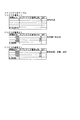
図18には、メインシナリオテーブルの一部として、シナリオ番号1,2,3の例を示している。各シナリオ番号のシナリオとしては、シナリオの各ライン(行)に時間データとしてメインシナリオタイマ(msTm)の値が記述されるとともに、サブシナリオ番号(scNo)、オプション(OPT)を記述することができる。即ちメインシナリオテーブルでは、メインシナリオタイマ(msTm)による時間として、実行されるべきサブシナリオ(及び場合によってはオプション)が指定される。またシナリオ最終行には、シナリオデータ終了コードD_SEEND、又はシナリオデータループコードD_SELOPが記述される。
なお、メインシナリオタイマ(msTm)の値は、メインシナリオの開始時から、16ms処理で行われるシナリオ更新の処理で+1されるため、「1」とは16msを示すものとなる。各シナリオ番号のシナリオテーブルは、或る行におけるメインシナリオタイマ(msTm)の時間を経過すると、次の行へ進むことになる。各行の時間データは、その行が終わるタイミングを示している。
例えばシナリオ番号2の場合、1500×16msの時間としてサブシナリオ番号2の動作が指定され、次の500×16msの時間としてサブシナリオ番号20の動作が指定され、次の2000×16msの時間としてサブシナリオ番号21の動作が指定されている。その次の行はシナリオデータ終了コードD_SEENDである。シナリオデータ終了コードD_SEENDの場合、シナリオ登録情報(ワーク)から、このシナリオが削除される(後述する図14のステップS617参照)。
FIG. 18 shows an example of
Since the value of the main scenario timer (msTm) is incremented by 1 in the scenario update process performed in the 16 ms process from the start of the main scenario, “1” indicates 16 ms. The scenario table of each scenario number advances to the next line when the time of the main scenario timer (msTm) in a certain line has elapsed. The time data of each line indicates the timing when the line ends.
For example, in the case of
次に図16Bでランプデータ登録情報の構造を説明する。ランプデータ登録情報としては、ランプサブシナリオテーブルから選択されたシナリオ、即ち装飾ランプ部63,64による演出動作(点灯パターン)を示す情報が登録される。このランプデータ登録情報も演出制御RAM202のワークエリアを用いて設定される。
本実施の形態では、ランプデータ登録情報は、ランプチャネルdwCH0〜dwCH15の16個のチャネルを有するものとされる。各ランプチャネルdwCH0〜dwCH15には優先順位が設定されており、ランプチャネルdwCH0からdwCH15に向かって順にプライオリティが高くなる。従ってランプチャネルdwCH15に登録されたシナリオ(ランプサブシナリオ)が最も優先的に実行される。また例えばランプチャネルdwCH3、dwCH10にシナリオが登録されていれば、ランプチャネルdwCH10に登録されたシナリオが優先実行される。
なお、ランプチャネルdwCH0は主にBGM(Back Ground Music)に付随するランプ演出、ランプチャネルdwCH15はエラー関係のランプ演出に用いられ、ランプチャネルdwCH1〜dwCH14が通常演出に用いられる。
Next, the structure of the lamp data registration information will be described with reference to FIG. 16B. As the lamp data registration information, a scenario selected from the lamp sub-scenario table, that is, information indicating a rendering operation (lighting pattern) by the
In the present embodiment, the ramp data registration information has 16 channels of ramp channels dwCH0 to dwCH15. Priorities are set for each of the ramp channels dwCH0 to dwCH15, and the priority increases in order from the ramp channels dwCH0 to dwCH15. Therefore, the scenario (lamp sub-scenario) registered in the ramp channel dwCH15 is executed with the highest priority. For example, if a scenario is registered in the ramp channels dwCH3 and dwCH10, the scenario registered in the ramp channel dwCH10 is preferentially executed.
The ramp channel dwCH0 is mainly used for a lamp effect associated with BGM (Back Ground Music), the lamp channel dwCH15 is used for an error-related lamp effect, and the lamp channels dwCH1 to dwCH14 are used for a normal effect.
各ランプチャネルdwCHに登録できる情報としては、図示のように、登録した点灯パターンの番号を示す登録点灯ナンバ(lmpNew)、実行する点灯パターンの番号を示す実行点灯ナンバ(lmpNo)、ランプサブシナリオの実行ラインを示すオフセット(offset)、実行時間(time)、チェックサム(checkSum)がある。 As shown in the figure, information that can be registered in each lamp channel dwCH includes a registered lighting number (lmpNew) indicating the number of the registered lighting pattern, an execution lighting number (lmpNo) indicating the number of the lighting pattern to be executed, and a lamp sub-scenario. There are an offset indicating an execution line (offset), an execution time (time), and a checksum (checkSum).
図19Aにランプサブシナリオテーブルの一部として、ランプサブシナリオ番号1,2,3の例を示している。各番号のランプサブシナリオとしては、シナリオの各ライン(行)に時間データ(time)の値が記述されるとともに、ランプチャネルと、各種の点灯パターンを示すランプナンバが記述される。また最終行には、ランプシナリオデータ終了コードD_LSENDが記述される。
FIG. 19A shows an example of lamp
このランプサブシナリオテーブルにおいて、各ラインの時間データ(time)は、そのサブシナリオが開始されてからの、当該ラインが開始される時間を示している。
16ms毎にメインシナリオタイマ(msTm)と、テーブルの時間データを比較して、一致した場合に、そのラインのランプナンバが、図16Bのランプデータ登録情報に登録される。登録されるランプチャネルdwCHは、当該ラインに示されたチャネルとなる。
例えば、上述の或るシナリオチャネルsCHにおいて、図18に示したシナリオ番号2が登録され、サブシナリオ番号2が参照されるとする。図19Aに示したランプサブシナリオ番号2では、1ライン目に時間データ(time)=0としてランプチャネル5(dwCH5)及びランプナンバ5が記述されている。この場合、メインシナリオタイマ(msTm)=0の時点で、まず当該1ライン目の情報が図16Bのランプデータ登録情報のランプチャネルdwCH5に、登録点灯ナンバ(lmpNew)=5として登録される。シナリオ登録情報(図16A)のサブシナリオ実行ラインlmp(lmpIx)の値は、次のラインの値(2ライン目)に更新される。これはランプチャネルdwCH5という比較的低い優先度で、点灯ナンバ5の点灯パターン動作の実行を行うための登録となる。
2ライン目については、500×16msとなった時点で同様の処理が行われる。即ちランプデータ登録情報のランプチャネルdwCH5に、登録点灯ナンバ(lmpNew)=6(つまり点灯ナンバ6の点灯パターンの指示)が登録される。
なお、時間データ(time)が連続する2ラインで同一の値であったら、その各ラインについての処理は同時に開始されることとなる。
後述するLED駆動データ更新処理では、このように更新されるランプデータ登録情報に基づいて、LED駆動データが作成される。
In this ramp sub-scenario table, the time data (time) of each line indicates the time at which the line is started after the sub-scenario is started.
When the main scenario timer (msTm) and the time data in the table are compared every 16 ms and they match, the lamp number of that line is registered in the lamp data registration information of FIG. 16B. The registered ramp channel dwCH is the channel indicated in the line.
For example, it is assumed that the
For the second line, the same processing is performed when it becomes 500 × 16 ms. That is, the registered lighting number (lmpNew) = 6 (that is, the
If the time data (time) has the same value for two consecutive lines, the processing for each line is started simultaneously.
In the LED drive data update process to be described later, LED drive data is created based on the lamp data registration information updated in this way.
次に図16Cでモータデータ登録情報の構造を説明する。モータデータ登録情報としては、音/モータサブシナリオテーブル(図19Bで後述)から選択されたシナリオを示す情報が登録される。このモータデータ登録情報も演出制御RAM202のワークエリアを用いて設定される。
本実施の形態では、モータデータ登録情報は、モータチャネルmCH0〜mCH7の8個のチャネルを有するものとされる。
各モータチャネルmCHに登録できる情報としては、図示のように、実行動作ナンバ(no)、登録動作ナンバ(noNew)、動作カウント(lcnt)、励磁カウンタ(tcnt)、実行ステップ(step)、動作ライン(offset)、親(移行元)/子(移行先)の属性(attribute)、親ナンバ(retNo)、戻りアドレス(retAddr)、ループ開始ポイント(roopAddr)、ループ回数(roopCnt)、エラーカウンタ(errCnt)、現在の入力情報(currentSw)、ソフト上のスイッチ情報(softSw)、ソフト上のカウント(softCnt)がある。
Next, the structure of the motor data registration information will be described with reference to FIG. 16C. As the motor data registration information, information indicating a scenario selected from the sound / motor sub-scenario table (described later in FIG. 19B) is registered. This motor data registration information is also set using the work area of the
In the present embodiment, the motor data registration information is assumed to have eight channels of motor channels mCH0 to mCH7.
Information that can be registered in each motor channel mCH includes execution operation number (no), registration operation number (noNew), operation count (lcnt), excitation counter (tcnt), execution step (step), operation line as shown in the figure. (Offset), parent (migration source) / child (migration destination) attribute (attribute), parent number (retNo), return address (retAddr), loop start point (roopAddr), loop count (roopCnt), error counter (errCnt) ), Current input information (currentSw), software switch information (softSw), and software count (softCnt).
また図17は、音データ登録情報を示している。音データ登録情報としては、音/モータサブシナリオテーブル(図19Bで後述)から選択されたシナリオを示す情報が登録される。この音データ登録情報も演出制御RAM202のワークエリアを用いて設定される。
本実施の形態では、音データ登録情報は、音チャネルaCH0〜aCH15の16個のチャネルを有するものとされる。この音チャネルaCH0〜aCH15のそれぞれは、音源IC59の入力チャネル(同じく16個)のそれぞれに対応するものである。
各音チャネルaCHに登録できる情報としては、図示のように、1次ボリューム遷移量(frzVq)、1次ボリューム(frzVl)、遷移量変化(rsv2)、ボリューム変化(rsv1)、フレーズ変化(rsv0)、ステレオ(frzSt)、ループ(frzLp)、フレーズ番号hi(frzHi)、フレーズ番号low(frzLo)、及び2次ボリューム(scdVl)がある。
FIG. 17 shows sound data registration information. As the sound data registration information, information indicating a scenario selected from the sound / motor sub-scenario table (described later in FIG. 19B) is registered. This sound data registration information is also set using the work area of the
In the present embodiment, the sound data registration information has 16 channels of sound channels aCH0 to aCH15. Each of the sound channels aCH0 to aCH15 corresponds to each of the input channels (also 16) of the
Information that can be registered in each sound channel aCH includes primary volume transition amount (frzVq), primary volume (frzVl), transition amount change (rsv2), volume change (rsv1), phrase change (rsv0) as shown in the figure. , Stereo (frzSt), loop (frzLp), phrase number hi (frzHi), phrase number low (frzLo), and secondary volume (scdVl).
ここで、1次ボリューム(第1ボリューム)とは、或るフレーズの再生開始を指示するシナリオデータ(後述するBGM、SE1、SE2、エラー)において、再生すべきフレーズのフレーズ番号の情報と共に記述されるボリューム情報である。
また、2次ボリューム(第2ボリューム)とは、1次ボリュームとの掛け合わせで最終的な再生ボリュームを定めるボリューム情報となる。
1次ボリュームと2次ボリュームとの違いは、以下の通りである。
1次ボリュームは、上記のようにフレーズの再生開始を指示するシナリオデータにも記述されるのに対し、2次ボリュームは後述する音コントロール(音制御情報)のシナリオデータに記述される。
また、本実施の形態の場合、1次ボリュームによっては、1次ボリューム遷移量(frzVq)の情報と組み合わされることで、再生中のフレーズに対するボリューム制御が可能とされ、該1次ボリュームの制御によってフレーズのフェードイン再生/フェードアウト再生が可能とされる。後述もするように、これらフェードイン再生/フェードアウト再生の指示は、音コントロールとしてのシナリオデータに基づき実行される。
2次ボリュームは、通常はパチンコ遊技機1の裏側に設けられたボリュームスイッチの状態に応じた値に設定され、後述するようにエラー時や所望のフレーズを消音させたいとき等にMAX値とは異なる値が設定される。
2次ボリュームの変化指示は、音コントロールとしてのシナリオデータによっても可能とされる(この点についても後述する)。
Here, the primary volume (first volume) is described together with the phrase number information of the phrase to be reproduced in the scenario data (BGM, SE1, SE2, error described later) instructing the start of reproduction of a certain phrase. Volume information.
The secondary volume (second volume) is volume information that determines the final reproduction volume by multiplying with the primary volume.
The difference between the primary volume and the secondary volume is as follows.
As described above, the primary volume is also described in the scenario data for instructing the start of phrase reproduction, whereas the secondary volume is described in the scenario data for sound control (sound control information) described later.
Further, in the case of the present embodiment, depending on the primary volume, volume control for the phrase being played back is possible by combining with the information of the primary volume transition amount (frzVq). Phrase fade-in playback / fade-out playback is enabled. As will be described later, these fade-in playback / fade-out playback instructions are executed based on scenario data as sound control.
The secondary volume is usually set to a value according to the state of the volume switch provided on the back side of the
The secondary volume change instruction can also be made by scenario data as sound control (this will also be described later).
1次ボリューム遷移量frzVqは、1次ボリュームを変化させる時間(速さ)を表す情報となる。
遷移量変化rsv2は、1次ボリューム遷移量frzVqを変化させるか否かを表す情報であり、ボリューム変化rsv1は、フレーズ再生時に1次ボリュームを変化させるか否かを表す情報となる。また、フレーズ変化rsv0はフレーズ番号を書き替えるか否かを表す情報であり、ステレオfrzStはステレオ再生/モノラル再生の何れであるか、ループfrzLpは無限ループ再生かループ再生しないかの何れかをそれぞれ表す情報となる。
The primary volume transition amount frzVq is information indicating the time (speed) for changing the primary volume.
The transition amount change rsv2 is information indicating whether or not the primary volume transition amount frzVq is changed, and the volume change rsv1 is information indicating whether or not the primary volume is changed during phrase reproduction. The phrase change rsv0 is information indicating whether or not the phrase number is rewritten. The stereo frzSt is either stereo playback or monaural playback, and the loop frzLp is either infinite loop playback or no loop playback. It becomes information to represent.
図示するように、1次ボリューム遷移量、1次ボリューム、2次ボリュームのデータサイズはそれぞれ1バイト(8ビット)である。また、遷移量変化、ボリューム変化、フレーズ変化、ステレオ、ループの各情報は1ビットされる。さらに、フレーズ番号hiは3ビット、フレーズ番号lowは1バイトとされる。即ち、フレーズ番号の情報は11ビットで構成され、従って最大で2048個のフレーズの指定が可能とされる。 As shown in the figure, the primary volume transition amount, the primary volume, and the data size of the secondary volume are each 1 byte (8 bits). Each information of transition amount change, volume change, phrase change, stereo, and loop is 1 bit. Furthermore, the phrase number hi is 3 bits, and the phrase number low is 1 byte. That is, the phrase number information is composed of 11 bits, so that a maximum of 2048 phrases can be specified.
ここで、本例において、ステレオ再生の場合は、隣接関係にある2つの音チャネルaCHを用いる。具体的には、偶数チャネルである音チャネルaCHnとその次の奇数チャネルである音チャネルaCHn+1とを使用する。
ステレオ再生を指示するシナリオデータには、ステレオ再生すべきフレーズを指定するためのフレーズ番号(指定情報としてはLchとRchとで共通の1つのフレーズ番号が用いられる)の情報と、ステレオ再生を指定するための情報とが記述され、該シナリオデータに基づき、音データ登録情報における偶数の音チャネルaCHnと奇数の音チャネルaCHn+1とにこれらフレーズ番号とステレオ再生の指示情報とが登録される(上述のフレーズ番号hi,lowとステレオfrzSt)。
In this example, in the case of stereo reproduction, two sound channels aCH that are adjacent to each other are used. Specifically, the sound channel aCHn that is an even channel and the sound channel aCHn + 1 that is the next odd channel are used.
In the scenario data instructing stereo playback, information on the phrase number for designating a phrase to be played back in stereo (one phrase number common to Lch and Rch is used as designation information) and stereo playback are designated. Based on the scenario data, the phrase number and stereo playback instruction information are registered in the even sound channel aCHn and the odd sound channel aCHn + 1 in the sound data registration information (described above). Phrase numbers hi, low and stereo frzSt).
図19Bは、音/モータサブシナリオテーブルの一部として、音/モータサブシナリオ番号1,2の例を示している。
各番号の音/モータサブシナリオとしては、シナリオの各ライン(行)に時間データ(time)の値(ms)が記述されるとともに、BGM、SE1、SE2、エラー音、音コントロール、モータ、ソレノイド/ユーザオプションの情報が記述可能とされる。また最終行には、シナリオデータ終了コードD_SEENDが記述される。
この音/モータサブシナリオテーブルに関しては、サブシナリオタイマ(scTm)の値が当該音/モータサブシナリオテーブル中の或るラインに記述された時間データ(time)の値になったら(なお最初は0である)、そのラインに記述されたBGM、SE1、SE2、エラー音、音コントロール、モータ、ソレノイド/ユーザオプションに応じた情報を音データ登録情報やモータデータ登録情報に登録することになる。
なお、各ラインの時間データ(time)は、当該ラインを開始するタイミングを示している。
FIG. 19B shows an example of sound /
As the sound / motor sub-scenario of each number, the time data (time) value (ms) is described in each line (row) of the scenario, and BGM, SE1, SE2, error sound, sound control, motor, solenoid / User option information can be described. In the last line, a scenario data end code D_SEEND is described.
With respect to this sound / motor sub-scenario table, if the value of the sub-scenario timer (scTm) becomes the value of time data (time) described in a certain line in the sound / motor sub-scenario table (initially 0) The information corresponding to the BGM, SE1, SE2, error sound, sound control, motor, solenoid / user option described in the line is registered in the sound data registration information and motor data registration information.
The time data (time) of each line indicates the timing at which the line is started.
ここで、音/モータサブシナリオテーブルにおけるSE(SE1及びSE2)とは、BGMとエラー音以外の演出に係る音を意味する。いわゆる予告演出時の音(予告音)は、このSEに分類される。
SE1とSE2の区別は、その音を出力する演出の出現頻度による別としている。例えば予告音であれば、その音を使用する予告演出の出現頻度(信頼度)による区別となる。本例の場合、SE2はSE1よりも出現頻度が低い演出に係る音とされる。
Here, SE (SE1 and SE2) in the sound / motor sub-scenario table means sound related to effects other than BGM and error sound. Sounds for so-called notice effects (notice sounds) are classified into this SE.
The distinction between SE1 and SE2 is made according to the appearance frequency of the effect that outputs the sound. For example, in the case of a notice sound, the distinction is made according to the appearance frequency (reliability) of the notice effect using the sound. In the case of this example, SE2 is a sound related to an effect having a lower appearance frequency than SE1.
音/モータサブシナリオテーブルにおけるBGM、SE1、SE2、エラー音の各情報は、それぞれフレーズ番号と1次ボリュームの情報とを含む。
これら音/モータサブシナリオテーブルに記述されたBGM、SE1、SE2、エラー音の情報は、音データ登録情報における何れかの音チャネルaCHに登録されることになるが、本実施の形態では、これらBGM、SE1、SE2、エラー音の音の種別ごとに、その情報内容を登録する音チャネルaCHを予め定めておくものとしている。
具体的に、音/モータサブシナリオテーブルに記述されたBGMの情報については、音チャネルaCH0(ステレオの場合は加えてaCH1)に登録する。また、SE1の情報については音チャネルaCH2〜aCH9のうちの空きチャネルに登録し、SE2の情報については音チャネルaCH10〜aCH14うちの空きチャネルに登録する。さらに、エラー音の情報については音チャネルaCH15に登録する。
このように本実施の形態では、音の種別と、その音についての音関連の情報を登録する音チャネルaCHとの対応関係が予め定められている。
Each information of BGM, SE1, SE2, and error sound in the sound / motor sub-scenario table includes a phrase number and primary volume information.
The BGM, SE1, SE2, and error sound information described in the sound / motor sub-scenario table are registered in one of the sound channels aCH in the sound data registration information. For each type of BGM, SE1, SE2, and error sound, a sound channel aCH for registering the information content is determined in advance.
Specifically, the BGM information described in the sound / motor sub-scenario table is registered in the sound channel aCH0 (in addition, in the case of stereo, aCH1). Further, information on SE1 is registered in an empty channel among the sound channels aCH2 to aCH9, and information on SE2 is registered in an empty channel among the sound channels aCH10 to aCH14. Further, information on the error sound is registered in the sound channel aCH15.
As described above, in the present embodiment, the correspondence between the type of sound and the sound channel aCH for registering sound-related information about the sound is determined in advance.
また、音/モータサブシナリオテーブルにおける音コントロールの情報は、再生中のフレーズをコントロールするための情報を記述したものである。
本実施の形態の場合、当該音コントロールの情報は4バイトで構成され、下位3バイトがコントロール対象のフレーズを指定するための情報、上位1バイトがコントロール情報(音のコントロール内容を表す情報)とされている。
The sound control information in the sound / motor sub-scenario table describes information for controlling the phrase being reproduced.
In the case of the present embodiment, the sound control information is composed of 4 bytes, the lower 3 bytes are information for designating a phrase to be controlled, and the upper 1 byte is control information (information indicating the control content of the sound) Has been.
ここで、本実施の形態では、音の種別と、その音についての情報を登録する音チャネルaCHとの対応を上述のように定めているが、このことは、BGMとしてのフレーズは音チャネルaCH0(ステレオの場合はaCH0及びaCH1)で再生され、SE1としてのフレーズは音チャネルaCH2〜aCH9の何れかで再生され、SE2としてのフレーズは音チャネルaCH10〜aCH14の何れかで再生され、エラー音としてのフレーズは音チャネルaCH15で再生されるということが一意に定まっていると換言できる。
このため、音コントロールの情報に基づき所定の種別の音(BGM/SE1/SE2/エラー音)をコントロールするとしたときは、音コントロールの情報を、その音に対応する音チャネルaCHに対して登録すればよい。
この点に鑑み本実施の形態の音コントロールの情報では、その下位3バイトの情報、即ちコントロール対象のフレーズを指定するための情報として、音チャネルaCHを指定する情報を記述する。つまり、コントロール対象とする音(フレーズ)が再生される音チャネルaCH(つまりBGM/SE1/SE2/エラー音の別に応じたaCH0(及びaCH1)/aCH2〜aCH9/aCH10〜aCH14/aCH15の別)を指定する情報が記述される。
Here, in the present embodiment, the correspondence between the type of sound and the sound channel aCH for registering information about the sound is determined as described above. This is because the phrase as BGM is the sound channel aCH0. (Stereo is aCH0 and aCH1), the phrase SE1 is reproduced on any of the sound channels aCH2 to aCH9, the phrase SE2 is reproduced on any of the sound channels aCH10 to aCH14, and an error sound In other words, it can be said that the phrase is reproduced on the sound channel aCH15.
Therefore, when a predetermined type of sound (BGM / SE1 / SE2 / error sound) is controlled based on the sound control information, the sound control information is registered for the sound channel aCH corresponding to the sound. That's fine.
In view of this point, in the sound control information of the present embodiment, information specifying the sound channel aCH is described as information of the lower 3 bytes, that is, information for specifying the phrase to be controlled. That is, the sound channel aCH (that is, aCH0 (and aCH1) / aCH2 to aCH9 / aCH10 to aCH14 / aCH15 according to the type of BGM / SE1 / SE2 / error sound) in which the sound (phrase) to be controlled is reproduced. Information to be specified is described.
なお、音/モータサブシナリオテーブルに記述されるBGM、SE1、SE2、エラー音、音コントロールの各情報を音データ登録情報としてワークに登録するための具体的な処理については図24〜図28により後述する。 It should be noted that specific processing for registering each information of BGM, SE1, SE2, error sound, and sound control described in the sound / motor sub-scenario table in the work as sound data registration information is shown in FIGS. It will be described later.
ここで、上記のように本実施の形態では、音の種別と、その音についての情報を登録する音チャネルaCHとの対応関係を予め定めておくようにしたことで、或る種別の音が再生される音チャネルaCHが一意に定まるようにできる。これにより、再生中の或る種別の音を制御するとしたときは、ワークにおけるその種別の音と対応づけられた音チャネルaCHに対して制御情報を登録すれば済み、制御対象とする音を再生中の音チャネルaCHを探索する必要はないものとできる。
従って探索処理が省略される分、演出動作に係る制御負荷を軽減できる。
In this embodiment, as described above, the correspondence between the sound type and the sound channel aCH in which information about the sound is registered is determined in advance, so that a certain type of sound is generated. The reproduced sound channel aCH can be uniquely determined. Thus, when a certain type of sound being played is controlled, it is only necessary to register control information for the sound channel aCH associated with that type of sound in the work, and the sound to be controlled is played back. It may be unnecessary to search for the middle sound channel aCH.
Therefore, the control load related to the rendering operation can be reduced as much as the search process is omitted.
また、上記のように本実施の形態では、再生中の音をコントロールするための音コントロールの情報を、コントロールの内容を表す情報と、制御対象とする音に対応する音チャネルaCHを表す情報とを組み合わせた情報としている。
このように音コントロール情報を、制御内容情報の登録先の音チャネルaCHの指定が可能な情報としたことでも、制御対象の音を再生中の音チャネルaCHを探索せずに済むものとできる。即ち、音コントロール情報をこのような構成とした点も、探索処理の省略、つまりは演出動作に係る制御負荷の軽減に寄与するものである。
Further, as described above, in the present embodiment, the sound control information for controlling the sound being reproduced includes information indicating the content of the control, and information indicating the sound channel aCH corresponding to the sound to be controlled. Information.
As described above, even when the sound control information is information that can designate the sound channel aCH that is the registration destination of the control content information, it is not necessary to search for the sound channel aCH that is reproducing the sound to be controlled. That is, the point that the sound control information has such a configuration also contributes to the omission of the search process, that is, the reduction of the control load related to the rendering operation.
説明を図19Bに戻す。
音/モータサブシナリオテーブルにおいて、モータのデータは、モータ1個につき1バイトでモータの動作パターン番号を示すように構成されている。
モータ番号に対応するモータチャネルに対して、この動作パターン番号がセットされる。
The description returns to FIG. 19B.
In the sound / motor sub-scenario table, the motor data is configured to indicate the motor operation pattern number in one byte for each motor.
This operation pattern number is set for the motor channel corresponding to the motor number.
図8のステップS111として説明した音再生処理では、図14,図15のシナリオ更新処理で更新される音データ登録情報に基づいて、再生出力が行われることになる。
また、図9のステップS203のモータ動作更新処理では、図14,図15のシナリオ更新処理で更新されるモータデータ登録情報に基づいて、モータ駆動データが作成される。
In the sound reproduction process described as step S111 in FIG. 8, reproduction output is performed based on the sound data registration information updated in the scenario update process in FIGS.
In the motor operation update process in step S203 of FIG. 9, motor drive data is created based on the motor data registration information updated in the scenario update process of FIGS.
これまでで説明した各情報を用いて実行されるシナリオ更新処理について、図14、図15を参照して説明する。
図8の16ms処理のステップS110として実行される図14のシナリオ更新処理では、演出制御CPU200はループ処理LP1として、シナリオチャネルsCH0〜sCH63のそれぞれについて、ステップS600〜S616の処理を行う。当該ループ処理の各回の処理対象のシナリオチャネルを「sCHn」として説明する。
Scenario update processing executed using each piece of information described so far will be described with reference to FIGS.
In the scenario update process of FIG. 14 executed as step S110 of the 16 ms process of FIG. 8, the
演出制御CPU200は、ステップS600でシナリオチャネルsCHnのメインシナリオ番号が0であるか否かを確認する。メインシナリオ番号が0である場合、当該シナリオチャネルsCHnは先の図12のシナリオ登録処理でメインシナリオの登録が為されていないチャネルsCHとなるので、該シナリオチャネルsCHnの情報更新は不要である。従ってこの場合は、ステップS615以下の処理を実行して処理を終える。具体的に、ステップS615でシナリオチャネルsCHn関連のデータのチェックサムを算出し、保存した上で、ステップS616でシナリオチャネルsCHn関連のデータをバックアップ保存する。これでシナリオチャネルsCHnについての1回の処理を終える。
The
一方、ステップS600でメインシナリオ番号が0でないとされた場合は、ステップS601に進み、シナリオチャネルsCHnの待機時間(delay)を確認する。待機時間(delay)=0でなければステップS602で待機時間(delay)の値を−1(デクリメント)する。そして、ステップS615及びS616の処理を実行して、シナリオチャネルsCHnについての1回の処理を終える。 On the other hand, if it is determined in step S600 that the main scenario number is not 0, the process proceeds to step S601, and the standby time (delay) of the scenario channel sCHn is confirmed. If the standby time (delay) = 0 is not satisfied, the value of the standby time (delay) is decremented by −1 (decrement) in step S602. And the process of step S615 and S616 is performed and the process of 1 time about scenario channel sCHn is finished.
ステップS601で待機時間(delay)=0であることが確認された場合は、演出制御CPU200はステップS603に進み、シナリオチャネルsCHnに登録されているメインシナリオ番号(mcNo)と、メインシナリオ実行ライン(mcIx)に対応するメインシナリオテーブルのアドレスを特定する。
ステップS604では、当該特定したアドレスで示される、メインシナリオテーブルの或るメインシナリオ番号の実行ラインが、終了コードD_SEEND(図18参照)が記述されている最終ラインであるか否かを確認する。
終了コードが記述された最終ラインで合った場合は、当該シナリオチャネルsCHnに登録されたシナリオで実行すべき処理は終了したことになるため、ステップS617で、そのシナリオチャネルsCHnに登録されているシナリオをシナリオ登録情報(ワーク)から削除する。
なお、この場合のシナリオ登録の削除は、シナリオ終了に応じた通常の削除である。先に図13で説明したシナリオ削除は、この通常削除以外の、例えば未終了のシナリオをシナリオ登録情報(ワーク)から削除する処理であることを付言しておく。
When it is confirmed in step S601 that the standby time (delay) = 0, the
In step S604, it is confirmed whether or not an execution line of a certain main scenario number in the main scenario table indicated by the specified address is a final line in which an end code D_SEEND (see FIG. 18) is described.
If the end code matches the last line in which the end code is described, the processing to be executed in the scenario registered in the scenario channel sCHn has been completed. Therefore, in step S617, the scenario registered in the scenario channel sCHn. Is deleted from the scenario registration information (work).
Note that the scenario registration deletion in this case is a normal deletion corresponding to the end of the scenario. It is added that the scenario deletion described above with reference to FIG. 13 is a process for deleting, for example, an unfinished scenario from the scenario registration information (work) other than the normal deletion.
ステップS617でシナリオ削除を行った後は、ステップS615に進む。 After the scenario is deleted in step S617, the process proceeds to step S615.
ステップS604で、メインシナリオテーブルの当該ラインが終了コードではない場合は、演出制御CPU200はステップS605に進み、まず当該シナリオチャネルsCHnのメインシナリオオプション(mcOpt)に、当該ラインのオプション(OPT)をセットする。次にステップS607で、ユーザオプション(userFn)に0を代入する。
そしてステップS608で当該シナリオチャネルsCHnで指定されるサブシナリオの更新を行う。サブシナリオの更新については図15で後述する。
If it is determined in step S604 that the line in the main scenario table is not an end code, the
In step S608, the sub-scenario specified by the scenario channel sCHn is updated. The sub-scenario update will be described later with reference to FIG.
ステップS609では、演出制御CPU200はメインシナリオタイマ(msTm)を+1(インクリメント)する。そしてステップS610では、メインシナリオタイマ(msTm)の値と、メインシナリオテーブルの該当ラインの時間データ(図18参照:msTmで記述)を比較する。先に述べたように、メインシナリオテーブルの各ラインの時間データは、そのラインの終了タイミングを規定するものであるから、メインシナリオタイマ(msTm)の値がメインシナリオテーブルの当該ラインに記述された時間データ以上であれば、そのラインの処理は終了し、次のラインを対象とする。従って、ステップS610でメインシナリオタイマ(msTm)の値がメインシナリオテーブルの当該ラインに記述された時間データ以上であるとされた場合は、ステップS611に進み、シナリオチャネルsCHnのメインシナリオ実行ライン(mcIx)を+1する。つまり次回は、次のラインが対象となるようにする。
また、ステップS610においてメインシナリオタイマ(msTm)の値がメインシナリオテーブルの当該ラインに記述された時間データ以上ではないとされた場合は、ステップS615に進む。
In step S609, the
If it is determined in step S610 that the value of the main scenario timer (msTm) is not equal to or greater than the time data described in the relevant line of the main scenario table, the process proceeds to step S615.
ステップS611でシナリオチャネルsCHnのメインシナリオ実行ライン(mcIx)を+1した後は、ステップS612で次のラインがループ指定であるか否かを確認する。図18のメインシナリオテーブルにおいてシナリオ番号1では、最終ラインがシナリオデータループコードD_SELOPとされている例を示したが、このようにループ指定されていた場合は、ステップS613で、メインシナリオ実行ライン(mcIx)にループ行をセットする。
またステップS612で次のラインはループ指定ではないとされた場合は、ステップS613を経由せずステップS614に進む。
After the main scenario execution line (mcIx) of the scenario channel sCHn is incremented by 1 in step S611, it is confirmed in step S612 whether or not the next line is designated as a loop. In
If it is determined in step S612 that the next line is not designated as a loop, the process proceeds to step S614 without going through step S613.
演出制御CPU200は、ステップS614では、1つのラインの終了に応じたクリア処理を行う。即ちメインシナリオタイマ(msTm)、サブシナリオタイマ(scTm)、サブシナリオ実行ライン(scIx)、サブシナリオ実行ラインlmp(lmpIx)、メインシナリオオプション(mcOpt)、ユーザオプション(userFn)、待機時間(delay)をクリアする。
そしてステップS615のチェックサム処理、ステップS616のバックアップ処理を行ってシナリオチャネルsCHnについての1回の処理を終える。
シナリオ更新処理としては、ループ処理LP1として、シナリオチャネルsCH0〜sCH63のそれぞれについて以上の処理が実行されることになる。
In step S614, the
Then, the checksum process in step S615 and the backup process in step S616 are performed, and one process for the scenario channel sCHn is completed.
As the scenario update process, the above process is executed for each of the scenario channels sCH0 to sCH63 as the loop process LP1.
ステップS608で行われるサブシナリオ更新処理を図15Aに詳細に示す。
メインシナリオタイマ(msTm)、シナリオチャネルsCHnと、メインシナリオテーブルに記述されたサブシナリオ番号(scNo)に基づいて、図15Aのサブシナリオの更新処理が行われる。
The sub-scenario update process performed in step S608 is shown in detail in FIG. 15A.
Based on the main scenario timer (msTm), the scenario channel sCHn, and the sub-scenario number (scNo) described in the main scenario table, the sub-scenario update process of FIG. 15A is performed.
まずステップS621で演出制御CPU200は、シナリオチャネルsCHnが0〜63のいずれかを示しているか否か、つまり適正値であるか否かを確認する。シナリオチャネルsCHnが64以上であれば、更新処理不能として図15の処理を終える。
シナリオチャネルsCHnが適正値であれば、演出制御CPU200はステップS622で、サブシナリオ番号(scNo)とサブシナリオ実行ラインlmp(lmpIx)に対応するランプサブシナリオテーブル(図19A参照)のアドレスを特定する。
First, in step S621, the
If the scenario channel sCHn is an appropriate value, the
演出制御CPU200はステップS623では、ランプチャネルカウント値を0をセットする。このランプチャンネルカウント値は、ランプデータ登録情報への点灯パターンナンバの登録がランプチャンネルdwCHの数(16)を超えて異常な回数行われてしまうことを防止するために演出制御CPU200が管理する値である。
In step S623, the
そして、演出制御CPU200はステップS624で、メインシナリオタイマ(msTm)とランプサブシナリオテーブルの時間データ(time)を比較する。ランプサブシナリオテーブルの時間データ(time)は、当該ライン(サブシナリオ実行ラインlmp(lmpIx)で示されるライン)が開始される時間(ms)を示している。従って、メインシナリオタイマの時間(実際にはmsTm×16msの時間)が、時間データ(time)以上となっていたら、そのラインについての処理を行う。その場合、ステップS625でランプチャネルカウント値が正常(ランプチャンネルdwCHの数である「16」以内)であるか否かを確認する。異常な値であれば処理を終える。正常な値であればステップS626で、現在のラインが、ランプシナリオデータ終了コードD_LSENDが記述されたラインであるか否かを確認する。
In step S624, the
ランプシナリオデータ終了コードD_LSENDが記述されたラインではなければ、演出制御CPU200はステップS627で、当該ラインに記述されているランプチャネル、ランプナンバを取得する。そしてステップS628で点灯パターンナンバの登録を行う。
点灯パターンナンバの登録処理を図15Bに示している。この場合、まず演出制御CPU200はステップS651で、当該ラインに記述されているランプチャネルdwCHの値が正常値であるか否かを判別する。正常値でなければ登録を行わずに処理を終える。
正常値であれば、ステップS652で、当該ラインに記述されているランプナンバが正常値であるか否かを判別する。正常値でなければ登録を行わずに処理を終える。
ランプチャネルdwCH及びランプ番号のいずれもが正常値であれば、ステップS653でワークのランプデータ登録情報における、ランプチャネルdwCHに対応する領域に登録点灯ナンバ(lmpNew)と実行点灯ナンバ(lmpNo)をセットする。即ちランプサブシナリオテーブルの当該ラインから取得したランプナンバを、登録点灯ナンバ(lmpNew)にセットし、「0」を実行点灯ナンバ(lmpNo)にセットする。
以上の図15Bの処理をステップS628で行ったら、演出制御CPU200はステップS629でサブシナリオ実行ラインlmp(lmpIx)の値を+1し、ステップS630でランプチャネルカウント値を+1してステップS624に戻る。
If it is not the line in which the lamp scenario data end code D_LSEND is described, the
The lighting pattern number registration process is shown in FIG. 15B. In this case, first, in step S651, the
If it is a normal value, it is determined in step S652 whether or not the ramp number described in the line is a normal value. If it is not a normal value, the process ends without performing registration.
If both the lamp channel dwCH and the lamp number are normal values, the registered lighting number (lmpNew) and the execution lighting number (lmpNo) are set in the area corresponding to the lamp channel dwCH in the lamp data registration information of the work in step S653. To do. That is, the lamp number acquired from the relevant line in the lamp sub-scenario table is set in the registered lighting number (lmpNew), and “0” is set in the execution lighting number (lmpNo).
15B is performed in step S628, the
ステップS624で、メインシナリオタイマの時間が、サブシナリオ実行ラインlmp(lmpIx)で示されるラインの時間データ(time)に達していない場合、及びステップS626でランプシナリオデータ終了コードD_LSENDが確認された場合は、演出制御CPU200の処理はステップS631へ進む。
When the time of the main scenario timer does not reach the time data (time) of the line indicated by the sub-scenario execution line lmp (lmpIx) in step S624, and the lamp scenario data end code D_LSEND is confirmed in step S626 The process of the
ステップS631では、メインシナリオテーブルに記述されているサブシナリオ番号と、現在処理中のシナリオチャネルsCHnに登録されているサブシナリオ実行ライン(scIx)に対応する音/モータサブシナリオテーブルのアドレスを特定する。
そして、ステップS632で、サブシナリオタイマ(scTm)の値がテーブルの時間データ(time)の値以上であるか否かを確認する。即ち、サブシナリオタイマ(scTm)の値が、現在処理中のシナリオチャネルsCHnに登録されているサブシナリオ実行ライン(sclx)で示されるラインの時間データ(time)の値以上であるか否かを確認する。
In step S631, the sub-scenario number described in the main scenario table and the address of the sound / motor sub-scenario table corresponding to the sub-scenario execution line (scIx) registered in the currently processed scenario channel sCHn are specified. .
In step S632, it is checked whether the value of the sub-scenario timer (scTm) is equal to or greater than the value of the time data (time) in the table. That is, whether or not the value of the sub-scenario timer (scTm) is equal to or greater than the value of the time data (time) of the line indicated by the sub-scenario execution line (sclx) registered in the currently processed scenario channel sCHn. Check.
ステップS632において、サブシナリオタイマ(scTm)の値がテーブルの時間データ(time)の値以上でなければ、そのラインに記述された情報についての登録処理は未だ実行するべきではないので、図のように音及びモータの登録を行わずにステップS640に進み、サブシナリオタイマ(scTm)の値をインクリメント(+1)して、この図15Aの処理を終えることとなる。 In step S632, if the value of the sub-scenario timer (scTm) is not equal to or greater than the value of the time data (time) in the table, the registration process for the information described in the line should not be executed yet, as shown in the figure. Then, the process proceeds to step S640 without registering the sound and the motor, the value of the sub-scenario timer (scTm) is incremented (+1), and the process of FIG. 15A is completed.
一方、ステップS632においてサブシナリオタイマ(scTm)の値がテーブルの時間データ(time)の値以上であれば、演出制御CPU200は処理をステップS633に進め、該当する音/モータサブシナリオ番号のテーブルの、サブシナリオ実行ライン(scIx)で示されるラインが、シナリオデータ終了コードD_SEENDが記述された行であるか否かを確認する。シナリオデータ終了コードD_SEENDが記述された行であれば処理を終了する。
シナリオデータ終了コードD_SEENDが記述された行でなければ、演出制御CPU200はステップS635で音の登録を行い、またステップS636でモータの登録を行う。これらステップS635,S636の登録処理としては、図19Bに例示したような音/モータサブシナリオテーブルの該当サブシナリオ番号の該当ラインの情報を、図17の音データ登録情報の音チャネルaCH、図16Cのモータデータ登録情報のモータチャネルmCHにそれぞれ登録する処理を行う。
なお、ステップS635として実行される音の登録の詳細な処理内容については後述する(図24〜図28)。
On the other hand, if the value of the sub-scenario timer (scTm) is equal to or greater than the value of the time data (time) in the table in step S632, the
If the scenario data end code D_SEEND is not described, the
The detailed processing contents of the sound registration executed as step S635 will be described later (FIGS. 24 to 28).
続いて、演出制御CPU200はステップS637で、当該ラインに記述されたソレノイド/ユーザオプションの情報を、シナリオ登録情報等に登録する。
そしてステップS638で、サブシナリオ実行ライン(scIx)の値として次のラインの値をセットする。さらにステップS640でサブシナリオタイマ(scTm)をインクリメントして処理を終える。
Subsequently, in step S637, the
In step S638, the value of the next line is set as the value of the sub-scenario execution line (scIx). Further, in step S640, the sub-scenario timer (scTm) is incremented and the process is terminated.
図8のステップS110では、以上の図14,図15の処理が行われることとなる。この処理でワーク上のシナリオ登録情報、ランプデータ登録情報、モータデータ登録情報、音データ登録情報が逐次更新され、これに応じて演出制御が行われることで、シナリオに沿った演出動作が実現される。 In step S110 in FIG. 8, the processes in FIGS. 14 and 15 are performed. Through this process, the scenario registration information, lamp data registration information, motor data registration information, and sound data registration information on the workpiece are sequentially updated, and effect control according to the scenario is realized by performing effect control accordingly. The
特に本実施の形態においては、第1のワークエリア(シナリオチャネルsCH0〜sCH63)には、演出種別を特定する演出データとしてシナリオ登録情報がセットされる。具体的にはメインシナリオ番号(mcNo)がセットされ、メインシナリオテーブル上のサブシナリオが特定される。さらに第1のワークエリアでは、音/モータサブシナリオテーブルの実行ラインを示すサブシナリオ実行ライン(scIx)、ランプサブシナリオテーブルの実行ラインを示すサブシナリオ実行ラインlmp(lmpIx)がセットされる。これらにより演出種別が特定される。
また実行する演出に応じた演出デバイスの動作データは第2のワークエリアにセットされる。第2のワークエリアとしてランプデータ登録情報をセットするランプチャネルdwCH1〜dwCH15、モータデータ登録情報をセットするモータチャネルmCH0〜mCH7、音データ登録情報をセットする音チャネルaCH0〜aCH15が用意されている。
即ち本実施の形態では、各種演出デバイスを用いた全体の演出データが第1のワークエリアにセットされ、その第1のワークエリアの演出データに基づき、第2のワークエリアで動作データがセットされることになる。
この場合、多様な演出設定のためには第1のワークエリアには、登録できる演出データ個数(シナリオ登録情報の個数)を比較的多くすることが好ましい。例えば演出データの登録チャネル数を多くしたい。そこでシナリオチャネルsCH0〜sCH63として64個のチャネルを用意する。
一方で、第2のワークエリアには、演出デバイスの動作を規定する動作データがセットされればよいため、動作データの登録可能数は、比較的少なくてもよい。特に、第2のワークエリアが、ランプ、モータ、音の個々の演出デバイスに対応して設けられているため、個々のデバイスについての登録可能数は、むやみに多くする必要はない。そこで第2のワークエリアとしては、ランプチャネルは16チャネル(dwCH1〜dwCH15)、モータチャネルは8チャネル(mCH0〜mCH7)、音チャネルは16チャネル(aCH0〜aCH15)としている。これらは、それぞれ対応する1つの演出デバイスについての動作データがセットされれば良いため、登録チャネル数は少なくても十分に多彩な演出動作に対応可能である。
このように、第1のワークエリアのチャネル数をN(例えばN=64),第2のワークエリアのチャネル数をM(例えばM=16、又はM=8)とすると、N>Mとなるように記憶領域を割り当てている。
これによって多彩な演出動作を可能としたまま、メモリが闇雲に消費されないようにしている。
Particularly in the present embodiment, scenario registration information is set in the first work area (scenario channels sCH0 to sCH63) as effect data for specifying the effect type. Specifically, the main scenario number (mcNo) is set, and the sub-scenario on the main scenario table is specified. Further, in the first work area, a sub-scenario execution line (scIx) indicating an execution line of the sound / motor sub-scenario table and a sub-scenario execution line lmp (lmpIx) indicating an execution line of the lamp sub-scenario table are set. The production type is specified by these.
Further, the operation data of the effect device corresponding to the effect to be executed is set in the second work area. Lamp channels dwCH1 to dwCH15 for setting lamp data registration information, motor channels mCH0 to mCH7 for setting motor data registration information, and sound channels aCH0 to aCH15 for setting sound data registration information are prepared as second work areas.
In other words, in the present embodiment, overall presentation data using various presentation devices is set in the first work area, and operation data is set in the second work area based on the presentation data of the first work area. Will be.
In this case, in order to set various effects, it is preferable to relatively increase the number of effects data (number of scenario registration information) that can be registered in the first work area. For example, I want to increase the number of registered channels for production data. Therefore, 64 channels are prepared as scenario channels sCH0 to sCH63.
On the other hand, since the operation data that defines the operation of the rendering device need only be set in the second work area, the number of registerable operation data may be relatively small. In particular, since the second work area is provided corresponding to each effect device for lamps, motors, and sounds, it is not necessary to unnecessarily increase the number that can be registered for each device. Therefore, as the second work area, the ramp channel is 16 channels (dwCH1 to dwCH15), the motor channel is 8 channels (mCH0 to mCH7), and the sound channel is 16 channels (aCH0 to aCH15). Since it suffices for the operation data for one corresponding production device to be set for each of them, it is possible to cope with a wide variety of production operations even if the number of registered channels is small.
Thus, if the number of channels in the first work area is N (for example, N = 64) and the number of channels in the second work area is M (for example, M = 16 or M = 8), N> M. The storage area is allocated as follows.
This keeps the memory from being consumed by the dark clouds while still allowing a variety of performance operations.
[4−6:LED駆動データ更新処理]
図8のステップS113のLED駆動データ更新処理を説明する。
この処理は、ランプデータ登録情報に登録されている点灯ナンバ(登録点灯ナンバ(lmpNew)、実行点灯ナンバ(lmpNo))に対応するランプデータテーブルを参照して、LED駆動データを作成する処理である。なお上述のように、ランプデータ登録情報の点灯ナンバには、元々はランプサブシナリオテーブルに記述された、点灯パターンを示すランプナンバがセットされる。ランプナンバは点灯パターンを示すナンバと述べたが、具体的には図23Aで述べるランプデータテーブルのランプデータの番号を示すことになる。
[4-6: LED drive data update process]
The LED drive data update process in step S113 of FIG. 8 will be described.
This process is a process for creating LED drive data with reference to the lamp data table corresponding to the lighting number (registered lighting number (lmpNew), execution lighting number (lmpNo)) registered in the lamp data registration information. . As described above, the lamp number indicating the lighting pattern originally set in the lamp sub-scenario table is set as the lighting number of the lamp data registration information. The lamp number has been described as the number indicating the lighting pattern, but specifically indicates the lamp data number of the lamp data table described in FIG. 23A.
図20はLED駆動データ更新処理を示している。
演出制御CPU200はステップS701でそれまで出力データとしていたLED駆動データをクリアする。 そしてループ処理LP2として、ランプデータ登録情報のランプチャネルdwCH0〜dwCH15のそれぞれについて、ステップS702〜S720の処理が行われる。以下、処理対象のランプチャネルを「dwCHn」と表記して説明する。
FIG. 20 shows LED drive data update processing.
In step S701, the
ステップS702では演出制御CPU200は、対象のランプチャネルdwCHnにおける実行点灯ナンバ(lmpNo)と登録点灯ナンバ(lmpNew)が一致しているか否かを確認する。先の図15BのステップS653のように点灯パターンナンバの登録が行われるため、実行点灯ナンバ(lmpNo)と登録点灯ナンバ(lmpNew)は最初は一致しない。一致していなければ点灯開始として、ステップS703で、実行点灯ナンバ(lmpNo)に登録点灯ナンバ(lmpNew)の値を代入する。またステップS704で、実行ライン(ofset)を0にセットし、また実行時間(time)を0にセットする。
なお実行点灯ナンバ(lmpNo)と登録点灯ナンバ(lmpNew)が一致していれば、既に過去に以上のステップS703,S704の処理が行われたものであるため、これらの処理は不要である。
In step S702, the
If the execution lighting number (lmpNo) matches the registered lighting number (lmpNew), the above steps S703 and S704 have already been performed, and these processes are unnecessary.
或るランプチャネルdwCHに登録された情報については、登録後、このLED駆動データ更新処理の機会毎に、その情報が反映されて各LEDドライバ90に出力するLED駆動データが作成されていく。
図21Aは、図16Bに示したワークのランプデータ登録情報において、ランプチャネルdwCH0、dwCH5、dwCH8に登録が行われている状態を示している。この図の状態は、図21Bの時点t0の状態の一例である。
即ちランプチャネルdwCH0、dwCH5の情報については、時点t0より以前に、LED出力データに反映されている。ランプチャネルdwCH0については、既に実行点灯ナンバ(lmpNo)と登録点灯ナンバ(lmpNew)が一致され、また実行ライン(ofset)は3(3ライン目)まで進んでいる。またランプチャネルdwCH5についても、既に実行点灯ナンバ(lmpNo)と登録点灯ナンバ(lmpNew)が一致され、また実行ライン(ofset)は2(2ライン目)まで進んでいる。時点t0では、ランプチャネルdwCH8は登録直後であり、まだ実行点灯ナンバ(lmpNo)と登録点灯ナンバ(lmpNew)が一致されていない。この後、上記ステップS703,S704の処理が行われることになる。
Regarding the information registered in a certain lamp channel dwCH, after the registration, the LED drive data to be output to each
FIG. 21A shows a state where registration is performed on the ramp channels dwCH0, dwCH5, and dwCH8 in the ramp data registration information of the workpiece shown in FIG. 16B. The state in this figure is an example of the state at time t0 in FIG. 21B.
That is, the information on the lamp channels dwCH0 and dwCH5 is reflected in the LED output data before time t0. For the lamp channel dwCH0, the execution lighting number (lmpNo) and the registered lighting number (lmpNew) have already been matched, and the execution line (ofset) has advanced to 3 (third line). Also, for the lamp channel dwCH5, the execution lighting number (lmpNo) and the registered lighting number (lmpNew) have already been matched, and the execution line (ofset) has advanced to 2 (second line). At time t0, the lamp channel dwCH8 is immediately after registration, and the execution lighting number (lmpNo) and the registration lighting number (lmpNew) are not matched. Thereafter, the processes in steps S703 and S704 are performed.
なお前述したように本実施の形態では、ランプチャネルdwCH0〜dwCH15には優先順位が設定されており、ランプチャネルdwCH0からdwCH15に向かって順にプライオリティが高くなる。図21Aに示すように、優先度の高いランプチャネルdwCH15はエラー報知用に使用される。ランプチャネルdwCH12,dwCH13,dwCH14等、優先度が高いランプチャネルは、連続予告や確定予告等、比較的信頼度の高い演出用などに用いられる。また優先度が中程度のランプチャネルは可動体演出用、優先度が比較的低いランプチャネルは、会話予告やステップアップ予告など比較的信頼度の低い演出用に用いられ、さらに優先度が低いランプチャネルは、通常変動、リーチ等に同期したランプ演出に用いられる。
このような優先度の設定のため、図21Bのように複数のランプチャネルdwCHの動作が重なる場合、優先度の高いランプチャネルの点灯動作が実行される。例えば時点t0からは、ランプチャネルdwCH0、dwCH5に基づく点灯動作が制限され、dwCH8に基づく点灯が行われるようにLED出力データが生成される。優先度の低いランプチャネルの情報を反映させないようにするためには、後述するマスクデータが使用される。
As described above, in the present embodiment, priority is set for the ramp channels dwCH0 to dwCH15, and the priority increases in order from the ramp channels dwCH0 to dwCH15. As shown in FIG. 21A, the lamp channel dwCH15 having a high priority is used for error notification. Lamp channels with high priority, such as the lamp channels dwCH12, dwCH13, dwCH14, etc. are used for relatively highly reliable performances such as continuous notices and final notices. The lamp channel with medium priority is used for moving body effects, and the lamp channel with relatively low priority is used for effects with relatively low reliability, such as conversation notices and step-up notices. Channels are used for ramp effects that are synchronized with normal fluctuations, reach, and the like.
Due to such priority setting, when the operations of a plurality of lamp channels dwCH overlap as shown in FIG. 21B, a lighting operation of a lamp channel with a high priority is executed. For example, from time t0, the lighting operation based on the lamp channels dwCH0 and dwCH5 is limited, and the LED output data is generated so that lighting based on dwCH8 is performed. In order not to reflect the information of the lamp channel having a low priority, mask data described later is used.
続いて図20のステップS705では、演出制御CPU200は実行点灯ナンバ(lmpNo)の値が正常範囲であるか否かを確認する。正常範囲とは、図23Aに示すランプデータテーブルのランプデータとして番号が存在する範囲である。
実行点灯ナンバ(lmpNo)が異常であれば、ステップS719に進む。なおランプチャネルdwCHnが登録されていない空きチャネルの場合も、ここでは異常としてステップS719に進む。
Subsequently, in step S705 of FIG. 20, the
If the execution lighting number (lmpNo) is abnormal, the process proceeds to step S719. In the case of an empty channel in which the lamp channel dwCHn is not registered, the process proceeds to step S719 as abnormal here.
実行点灯ナンバ(lmpNo)が正常であれば、ステップS706に進む。ステップS706では演出制御CPU200は、ランプチャネルdwCHnに登録された実行点灯ナンバ(lmpNo)、実行ライン(ofset)に対応する、ランプデータテーブルのアドレスを特定する。
またステップS707では、ランプチャネルdwCHnに登録された実行点灯ナンバ(lmpNo)、マスクデータテーブルのアドレスを特定する。
アドレスの特定のためには演出制御CPU200は、図22のようなランプデータアドレステーブルを参照する。このランプデータアドレステーブルには、各点灯パターン、例えば全体点滅、右側点滅、左側点滅、役物点灯などを実現するためのランプデータ番号のアドレスが示されている。図22の左端の数字は、図19Aのランプサブシナリオテーブルで示されるランプナンバであり、例えばランプナンバ2のランプデータのアドレスの欄には、全体点滅の点灯パターンを行うためのランプデータ番号が記憶されたアドレスが記述されている。
また、マスクデータのアドレスの欄には、そのランプデータ番号の点灯パターンを実行する際に必要なマスクデータが記憶されたアドレスが記憶されている。例えば点灯ナンバ5の右側点滅の点灯パターンを行う際には、センターケースマスクが必要になるが、そのセンターケースマスクを行うためのマスクデータのアドレスが記述されている。
If the execution lighting number (lmpNo) is normal, the process proceeds to step S706. In step S706, the
In step S707, the execution lighting number (lmpNo) registered in the lamp channel dwCHn and the address of the mask data table are specified.
To specify the address, the
In the address field of mask data, an address where mask data necessary for executing the lighting pattern of the lamp data number is stored is stored. For example, when a lighting pattern of blinking on the right side of the
図23Aにはランプデータテーブルの一部としてランプデータ1,2を示している。
各番号のランプデータにおける各ラインには、タイマ(frame)としての時間データと点灯データが記述されている。タイマ(frame)は各ラインの点灯データによるLED出力データの生成を行う時間を規定する。
点灯データは、各LEDドライバ90に対応して記述されている。先に図4では、枠ドライバ部61にはn個、盤ドライバ部62にはm個のLEDドライバ90が存在するとしたが、以下では一例として、枠ドライバ部61には4個、盤ドライバ部62には5個の、合計9個のLEDドライバ90が存在すると仮定して説明する。
その場合、ランプデータの各ラインには、図23Aに示すように、9個のLEDドライバ90のそれぞれに対応して点灯データが記述される。なお図では各LEDドライバ90との対応をLEDドライバ90のスレーブアドレスでw1〜w4、b1〜b5で示している。
点灯データとしては、図4,図5で説明した、LEDドライバ90の1つの出力端子96(1系列のLED駆動電流出力)に対して4ビット(0h〜Fh)が割り当てられ(「h」は16進表記を示す)、16階調の輝度を指定するようにされている。図5で述べたように、LEDドライバ90には24個の出力端子96−1〜96−24がある。このため、1つの点灯データは、「FFFF000055550000AAAAAAAA(h)」のように、(4×24)ビットの情報となる。仮に図示のランプデータ1の1ライン目のように、LEDドライバ90(w1)についての点灯データが、「FFFF00000000000055550000(h)」であれば、LEDドライバ90(w1)の出力端子96−1〜96−4からは最大輝度「F」を発光させるための駆動電流を出力し、出力端子96−5〜96−16及び96−21〜96−24は非発光(最低輝度)、出力端子96−17〜96−20は輝度「5」としての駆動電流を出力することを指定する情報となる。
ランプデータにはこのような点灯データが、各LEDドライバ90(w1〜w4、b1〜b5)のそれぞれに対して設定されて、かつそれらが各ライン毎に設定されることで、時系列的に変化する所定の発光パターンが示されることになる。(図では点灯データは一部のみに例示した。空欄部分は図示を省略したもので、実際には点灯データが記述される)
FIG. 23A shows
Each line in each number of lamp data describes time data and lighting data as a timer (frame). The timer (frame) defines the time for generating the LED output data based on the lighting data of each line.
The lighting data is described corresponding to each
In that case, lighting data is described in each line of the lamp data corresponding to each of the nine
As the lighting data, 4 bits (0h to Fh) are assigned to one output terminal 96 (one series of LED drive current outputs) of the
In the lamp data, such lighting data is set for each of the LED drivers 90 (w1 to w4, b1 to b5), and is set for each line, so that time series. A predetermined light emission pattern that changes is shown. (In the figure, the lighting data is illustrated only in part. The blank portion is not shown, and the lighting data is actually described.)
図23Bにはマスクデータテーブルの例として、マスクデータ1〜5を示している。各マスクデータは、枠側の装飾ランプ20wの駆動についてのマスクのための、盤側の装飾ランプ20bの駆動についてのマスクのため、全体のマスクのため、センターケースのマスクのため、役物のマスクのためなどとして、必要なマスクパターンが記憶されている。
各マスクデータ1〜5は、それぞれ各LEDドライバ90(w1〜w4、b1〜b5)の各出力端子96−5〜96−24について、消灯を「0h」、マスク無しを「Fh」で示すデータとされている。
例えばマスクデータ1についてみると、枠ドライバ部61におけるLEDドライバ90(w1〜w4)については、「0000・・・・・00(h)」と、各出力端子96−5〜96−24について消灯が設定され、盤ドライバ部62のLEDドライバ90(b1〜b5)については、「FFFF・・・・・FF(h)」と、各出力端子96−5〜96−24についてマスク無しが設定されている。つまり枠側の装飾ランプ20wのみをマスクすることを指定するデータとなる。(なお、マスクデータ4,5はデータ値の図示を省略している)
FIG. 23B shows
The
For example, in the
図20のステップS706,S707では、このようなランプデータテーブル、マスクデータテーブルにおいて、処理中のランプチャネルdwCHnに対応するアドレスを特定するものである。
続いてステップS708で演出制御CPU200は、ランプデータテーブルの該当ライン(現在対象のランプチャネルdwCHnの実行ライン(offset)で示されるライン)のタイマ(frame)を取得し、これを変数Dtimeに代入する。
In steps S706 and S707 in FIG. 20, an address corresponding to the lamp channel dwCHn being processed is specified in the lamp data table and the mask data table.
Subsequently, in step S708, the
ステップS709で演出制御CPU200は、上記ステップS706,S707で特定した該当の点灯データとマスクデータを展開し、LED駆動データを生成していく。この処理については後述するが、現在処理中のランプチャネルdwCHnについての点灯データとマスクデータを、出力するLED駆動データに反映させる処理となる。
In step S709, the
ステップS710ではランプチャネルdwCHnの情報である実行時間(time)を+1する。
ステップS711では変数Dtimeと実行時間(time)を比較する。変数Dtimeには現在実行中のラインのタイマ(frame)が代入されている。実行時間(time)はLED駆動データ更新処理毎(16ms毎)に上記ステップS710で+1される。従ってDtime≦timeとなれば、現ラインの終了タイミングとなる。Dtime≦timeではなければ、まだ現在のラインの終了に至らないとしてステップS711からS719に進む。Dtime≦timeの場合は、現在のラインの終了としてステップS711からS712に進む。
演出制御CPU200はステップS712で実行時間(time)を0にリセットする。またステップS713で、実行ライン(offset)の値を+1する。つまり次のラインが対象となるようにする。
ステップS714では演出制御CPU200は、実行ライン(offset)に対応するランプデータテーブル該当ラインのアドレスを特定する。そしてステップS715,S717で、そのラインに終了コード(D_DTEND)が記述されているか、ループコード(LMP_LP)が記述されているかを確認する。
終了コード(D_DTEND)が記述されていた場合は、ステップS716で、当該ランプチャネルdwCHnの登録点灯ナンバを0に更新する。つまりワーク上で、当該ランプチャネルdwCHの登録に応じた処理が完了したことを示すようにする。
ループコード(LMP_LP)が記述されていた場合はステップS718で、実行ライン(offset)の値をループ先のアドレスに更新する。
In step S710, the execution time (time), which is information of the ramp channel dwCHn, is incremented by one.
In step S711, the variable Dtime is compared with the execution time (time). The timer (frame) of the currently executing line is assigned to the variable Dtime. The execution time (time) is incremented by 1 in step S710 for each LED drive data update process (every 16 ms). Therefore, if Dtime ≦ time, the current line end timing is reached. If Dtime ≦ time is not satisfied, it is determined that the end of the current line has not yet been reached, and the process proceeds from step S711 to S719. If Dtime ≦ time, the process proceeds from step S711 to S712 as the end of the current line.
The
In step S714, the
If the end code (D_DTEND) is described, the registered lighting number of the lamp channel dwCHn is updated to 0 in step S716. In other words, it indicates that the processing corresponding to the registration of the lamp channel dwCH is completed on the work.
If the loop code (LMP_LP) has been described, the value of the execution line (offset) is updated to the loop destination address in step S718.
ステップS719では演出制御CPU200は、ランプチャネルdwCHnの時点のLED駆動データのチェックサムを算出する。またステップS720でバックアップ用データを保存する。
以上で、1つのランプチャネルdwCHnを対象としたLEDデータ更新を終える。ループ処理LP2として、以上の処理をランプチャネルdwCH0〜dwCH15まで順次行うことになる。
In step S719, the
This completes the LED data update for one lamp channel dwCHn. As the loop processing LP2, the above processing is sequentially performed up to the ramp channels dwCH0 to dwCH15.
各ランプチャネルdwCHnでのLED出力データの更新は、ステップS709で行われるが、これは次のような処理となる。
点灯データとマスクデータを展開してLED駆動データを生成する出力データバッファは、ランプデータテーブル及びマスクデータテーブルと同様に、各LEDドライバ90(w1〜w4、b1〜b5)のそれぞれに対応して用意される。例えば1つのLEDドライバ90に対応する(4×24)ビットの情報の領域が、例えば9個のLEDドライバ90(w1〜w4、b1〜b5)のそれぞれに対して設けられる。この場合、出力データバッファは9×(4×24)ビットのバッファ領域とされる。
The LED output data is updated in each lamp channel dwCHn in step S709, and this is the following process.
The output data buffer that generates the LED drive data by expanding the lighting data and the mask data corresponds to each of the LED drivers 90 (w1 to w4, b1 to b5), similarly to the lamp data table and the mask data table. Prepared. For example, an information area of (4 × 24) bits corresponding to one
このような出力データバッファに対して、ステップS709では、マスクデータをアンド(論理積)で展開し、点灯データをオア(論理和)で展開する処理が行われる。これがループ処理(LP2)により、各ランプチャネルdwCH0〜dwCH15について順次ステップS709で行われる。
例えば図21で示した時点t0の場合、出力データバッファは、ランプデータ2のマスクデータ(図22参照:マスクなし)がアンド展開され、ランプデータ2の3ライン目の点灯データがオア展開された状態の後、ランプデータ5のマスクデータ(図22参照:センターケースマスク)がアンド展開され、ランプデータ5の2ライン目の点灯データがオア展開された状態となっている。
上述の通りマスクデータは0h(=0000)が消灯、Fh(=1111)がマスクなしである。従ってマスクデータをアンドで展開するということは、その時点までの出力データバッファの値について、消灯(マスク)したいビットを「0」とし、マスクしないビットは変更しないということになる。
さらに点灯データをオアで展開するということは、処理中のランプチャネルdwCHの点灯データが、マスク後の出力データバッファに反映させるということになる。
この処理をランプチャネルdwCH0〜dwCH15について順次行うことで、高い番号のランプチャネルほど優先されたLED駆動データが出力データバッファ上に形成されることになる。
For such an output data buffer, in step S709, a process of developing the mask data with AND (logical product) and developing the lighting data with OR (logical sum) is performed. This is sequentially performed in step S709 for each of the lamp channels dwCH0 to dwCH15 by loop processing (LP2).
For example, at the time point t0 shown in FIG. 21, the output data buffer is AND-expanded with the mask data of the lamp data 2 (see FIG. 22: no mask), and the lighting data of the third line of the
As described above, in the mask data, 0h (= 0000) is extinguished and Fh (= 1111) is no mask. Therefore, expanding the mask data with AND means that the bit to be extinguished (masked) is set to “0” in the output data buffer value up to that point, and the bits not masked are not changed.
Further, when the lighting data is expanded OR, the lighting data of the lamp channel dwCH being processed is reflected in the output data buffer after masking.
By sequentially performing this process for the lamp channels dwCH0 to dwCH15, the LED drive data that is prioritized for the higher-numbered lamp channels is formed on the output data buffer.
以上のようなLEDデータ更新処理で生成されたLED駆動データは、先の図9で説明した1msタイマ割込処理のステップS205(但し上述のケース12〜15の場合)で、実際に各LEDドライバ90に出力され、これによってシナリオデータに応じたランプ演出動作が実現される。
The LED drive data generated by the LED data update process as described above is actually sent to each LED driver in step S205 (in the
[4−7:音の登録処理]
続いて、図15のステップS635として実行する音の登録処理について説明する。
この音の登録処理は、図19Bに例示した音/モータサブシナリオテーブルの記述内容(サブシナリオデータ)に応じた情報を、図17の音データ登録情報の音チャネルaCHに登録する処理となる。
[4-7: Sound registration processing]
Next, the sound registration process executed as step S635 in FIG. 15 will be described.
This sound registration processing is processing for registering information corresponding to the description content (subscenario data) of the sound / motor sub-scenario table illustrated in FIG. 19B in the sound channel aCH of the sound data registration information of FIG.
図24は、音の登録処理を示している。
まず、演出制御CPU200はステップS800で、音/モータサブシナリオテーブルに音データが存在するか否かを判別する。即ち、音/モータサブシナリオテーブルの当該サブシナリオ番号の該当ラインの記述情報として、BGM/SE1/SE2/エラー音/音コントロールの何れかの情報が存在するか否かを判別する。
これらの音データが存在しない場合は処理を終える。
FIG. 24 shows a sound registration process.
First, the
If these sound data do not exist, the process ends.
一方、これら音データの何れかが存在する場合、演出制御CPU200は、ステップS801でBGMか否かを判別する。音データがBGMであった場合、演出制御CPU200はステップS802で音/モータサブシナリオテーブルの音データを音チャネルaCH0にセットする。即ち、音/モータサブシナリオテーブルの当該サブシナリオ番号の該当ラインに記述されたBGMの情報を、音データ登録情報における、当該BGMに対応づけられた音チャネルaCHとしての音チャネルaCH0に登録する。
先に説明したように、音データがBGM、SE1、SE2、エラー音の場合、その記述内容(つまりシナリオデータ)としては少なくとも再生すべきフレーズのフレーズ番号とその1次ボリュームの情報と、ループ再生やステレオ再生の有無に関する情報とが含まれ、従ってこれらの情報が音データ登録情報に登録される。
なお、BGM、SE1、SE2についてはステレオ再生が可能とされ、その場合は音/モータサブシナリオテーブルのBGM、SE1、SE2の情報でその指示が為される。例えばBGMがステレオ再生される場合、音チャネルaCH0のみでなく音チャネルaCH1も使用される。この場合、これら音チャネルaCH0、aCH1のうち、偶数チャネルである音チャネルaCH0に、フレーズ番号(frzHi、frzLo)としてBGMの情報に記述されたフレーズ番号が登録されると共に、ステレオ(frzSt)の情報として「1」が記述される。またループ再生をする場合には、ループ(frzLp)の情報として「1」が記述される。
On the other hand, if any of these sound data exists, the
As described above, when the sound data is BGM, SE1, SE2, and error sound, the description content (that is, scenario data) includes at least the phrase number of the phrase to be reproduced, information on the primary volume, and loop reproduction. And information regarding the presence / absence of stereo playback are included, and thus these pieces of information are registered in the sound data registration information.
Note that BGM, SE1, and SE2 can be played back in stereo, and in that case, the instruction is given by the information of BGM, SE1, and SE2 in the sound / motor sub-scenario table. For example, when BGM is reproduced in stereo, not only the sound channel aCH0 but also the sound channel aCH1 is used. In this case, among the sound channels aCH0 and aCH1, the phrase number described in the BGM information is registered as the phrase number (frzHi, frzLo) in the even channel sound channel aCH0, and stereo (frzSt) information is registered. “1” is described. When loop playback is performed, “1” is described as loop (frzLp) information.
ステップS802でBGMの音データをセットした場合、或いはステップS801で音データがBGMでないとされた場合、演出制御CPU200はステップS803で音データがエラー音か否かを判別し、エラー音であった場合はステップS804で音/モータサブシナリオテーブルの音データを音チャネルaCH15にセットする。即ち、エラー音に対応する音チャネルaCHとしての音チャネルaCH15にサブシナリオデータの記述内容に応じた情報を登録する。
If BGM sound data is set in step S802, or if the sound data is not BGM in step S801, the
ステップS804でエラー音の音データをセットした場合、或いはステップS803で音データがエラー音でないとされた場合、演出制御CPU200はステップS805で音データがSE1か否かを判別し、SE1であった場合はステップS806でSE1の設定処理を行う。
そして、ステップS806でSE1の設定処理を実行した場合、或いはステップS805で音データがSE1でないとされた場合、演出制御CPU200はステップS807で音データがSE2か否かを判別し、SE2であった場合はステップS808でSE2の設定処理を行う。
さらに、ステップS808でSE2の設定処理を実行した場合、或いはステップS807で音データがSE2でないとされた場合、演出制御CPU200はステップS809で音データが音コントロールか否かを判別し、音コントロールであった場合はステップS810で音コントロールの設定処理を行う。
ステップS810で音コントロールの設定処理を実行した場合、或いはステップS805で音データが音コントロールでないとされた場合、演出制御CPU200は図24に示す処理を終える。
When the sound data of the error sound is set in step S804, or when the sound data is not an error sound in step S803, the
If the SE1 setting process is executed in step S806, or if the sound data is not SE1 in step S805, the
Further, when the SE2 setting process is executed in step S808, or when the sound data is not SE2 in step S807, the
When the sound control setting process is executed in step S810, or when the sound data is not sound control in step S805, the
以下、上記のステップS806、S808、S810でそれぞれ実行するSE1の設定処理、SE2の設定処理、音コントロールの設定処理の内容を個別に説明する。 The contents of the SE1 setting process, SE2 setting process, and sound control setting process executed in steps S806, S808, and S810, respectively, will be described individually.
まず図25により、ステップS806、S808でそれぞれ実行するSE1の設定処理、SE2の設定処理の内容について説明する。
なお、これらSE1の設定処理、SE2の設定処理の内容は、音データの登録対象とする音チャネルaCH(対応音チャネルaCH)が異なる以外は共通であるため、当該図25の一図での説明とする。
First, the contents of the SE1 setting process and SE2 setting process executed in steps S806 and S808, respectively, will be described with reference to FIG.
The contents of the SE1 setting process and SE2 setting process are the same except that the sound channel aCH (corresponding sound channel aCH) to be registered for the sound data is different. And
まず演出制御CPU200はステップS901で、対応音チャネルaCHの再生状態を取得する。前述のように本実施の形態では音の種別ごとに登録を行うべき音チャネルaCHの対応が定められており、SE1の場合は音チャネルaCH2〜aCH9が、またSE2の場合は音チャネルaCH10〜aCH14がそれぞれ対応音チャネルaCHとなる。
従って、ステップS901の処理は、SE1の設定処理(S806)として実行される場合は音チャネルaCH2〜aCH9の再生状態を取得する処理となり、SE2の設定処理(S808)として実行される場合は音チャネルaCH10〜aCH14の再生状態を取得する処理となる。
各音チャネルaCHの再生状態の取得、即ちフレーズを再生中であるか否かの情報の取得は、音源IC59に音チャネルaCHごとに設けられた再生状態情報格納レジスタの値を取得することで行う。
First, the
Therefore, the process of step S901 is a process of acquiring the playback state of the sound channels aCH2 to aCH9 when executed as the SE1 setting process (S806), and the sound channel when executed as the SE2 setting process (S808). This is a process of acquiring the playback state of aCH10 to aCH14.
Acquisition of the reproduction state of each sound channel aCH, that is, acquisition of information on whether or not a phrase is being reproduced, is performed by acquiring the value of a reproduction state information storage register provided for each sound channel aCH in the
次に、ステップS902では演出制御CPU200は、設定音チャネルaCHをスタート音チャネルaCHに設定する。ここで、設定音チャネルaCHとは、音データ登録の対象とする音チャネルaCHを意味する。また、スタート音チャネルaCHとは、対応音チャネルaCHのうち最もチャネル番号の小さい音チャネルaCHを意味し、SE1の場合はaCH2、SE2の場合はaCH10が該当する。
以下のステップS903〜S911の処理により、スタート音チャネルaCHから順に空きチャネルを探索してSEの音データの登録を行うべく、ステップS902で設定音チャネルaCHをスタート音チャネルaCHに設定する。
Next, in step S902, the
In step S902, the set sound channel aCH is set as the start sound channel aCH in order to search for an empty channel in order from the start sound channel aCH and register SE sound data by the processing in steps S903 to S911.
ステップS903では演出制御CPU200は、設定音チャネルaCHは再生中であるか否かを判別する。設定音チャネルaCHが再生中であれば、ステップS908で設定音チャネルaCHを+1するとともに、ステップS909で設定音チャネルaCHがエンドチャネルより大であるか否かを判別する。エンドチャネルとは、対応音チャネルaCHのうちチャネル番号が最も大きい音チャネルaCHを意味し、従ってSE1の場合は音チャネルaCH9より大であるか否か、SE2の場合は音チャネルaCH14より大であるか否かをそれぞれ判別することになる。
設定音チャネルaCHがエンドチャネルより大である場合は、対応音チャネルaCHに空きがないことから処理を終了する。
一方、設定音チャネルaCHがエンドチャネルより大でない場合はステップS903に戻る(つまり次の音チャネルaCHについて再生中か否かの判別が行われる)。
In step S903, the
If the set sound channel aCH is larger than the end channel, the corresponding sound channel aCH is empty, and the process ends.
On the other hand, if the set sound channel aCH is not larger than the end channel, the process returns to step S903 (that is, it is determined whether or not the next sound channel aCH is being reproduced).
ステップS903で設定音チャネルaCHは再生中でないとされた場合、演出制御CPU200はステップS904に進み、設定音チャネルaCHのワークに音データがないか否かを判別する。
設定音チャネルaCHに音データがある、つまり設定音チャネルaCHは空きではないとされた場合、演出制御CPU200はステップS908に進む。つまりこれにより、対応音チャネルaCH内における次の空きチャネルを探索するようにされる。
If it is determined in step S903 that the set sound channel aCH is not being reproduced, the
If there is sound data in the set sound channel aCH, that is, if the set sound channel aCH is not empty, the
一方、設定音チャネルaCHに音データがない、つまり設定音チャネルaCHが空きであるとされた場合、演出制御CPU200はステップS905に進み、ステレオ要求があるか否かを判別する。即ち、テーブルのSEの情報中におけるステレオ再生か否かを表す情報を参照して、当該SEの情報が、ステレオ再生の要求を伴うものであるか否かを判別する。なお、前述のようにステレオ再生を要求するシナリオデータには、LchとRchの個別のフレーズ番号は記述されず、共通の1つのフレーズ番号が記述されている。
On the other hand, if there is no sound data in the set sound channel aCH, that is, it is determined that the set sound channel aCH is empty, the
ステレオ要求があった場合、演出制御CPU200はステップS906に進み、設定音チャネルaCHが偶数チャネルであるか否かを判別する。設定音チャネルaCHが偶数チャネルでなければ、演出制御CPU200はステップS908に進み、設定音チャネルaCHを+1する。即ち、次の音チャネルaCH以降で空きチャネルを探索する。
前述のように本例では、ステレオ再生は偶数の音チャネルaCHnとその次の奇数の音チャネルaCHn+1とを使用する。このためステレオ再生を要求するシナリオデータに応じては、連続した偶数・奇数の空きチャネルを探索することを行う。そこでステップS906で設定音チャネルaCHが偶数チャネルでなければ、次の音チャネルaCH以降で空きチャネルを探索するようにしている。
またステップS906で設定音チャネルaCHが偶数チャネルであれば、演出制御CPU200はステップS907に進み、設定音チャネルaCHの次の音チャネルaCHも空きチャネルであるか否か(再生中でないかも含めて空きチャネルであるか否か)を判別する。
設定音チャネルaCHの次の音チャネルaCHが空きチャネルでなければ、ステップS908に進む。つまり、対応音チャネルaCH内での次の空きチャネルを探索する。
設定音チャネルaCHの次の音チャネルaCHが空きチャネルであれば、連続する偶数の音チャネルaCHnとその次の奇数の音チャネルaCHn+1とが使用できることになる。そこでステップS911に進んで、テーブルの音データを設定音チャネルaCHに対応したワークの領域にセットし、処理を終了する。本実施の形態では、連続する偶数、奇数の音チャネル(aCHn、aCHn+1)のうち、偶数の音チャネルaCHnのみに音データをセットする。
If there is a stereo request, the
As described above, in this example, the stereo reproduction uses the even-numbered sound channel aCHn and the next odd-numbered sound
If the set sound channel aCH is an even channel in step S906, the
If the sound channel aCH next to the set sound channel aCH is not an empty channel, the process proceeds to step S908. That is, the next empty channel in the corresponding sound channel aCH is searched.
If the sound channel aCH next to the set sound channel aCH is an empty channel, the continuous even-numbered sound channel aCHn and the next odd-numbered sound channel aCHn + 1 can be used. In step S911, the sound data in the table is set in the work area corresponding to the set sound channel aCH, and the process ends. In the present embodiment, the sound data is set only to the even-numbered sound channel aCHn among the even-numbered and odd-numbered sound channels (aCHn, aCHn + 1).
ステップS905でステレオ要求がないとされた場合、つまりモノラル要求の場合は、演出制御CPU200はステップS910に進み、現在の設定音チャネルaCHが偶数チャネルであるか否かを確認する。偶数チャネルであれば、ステップS911に進んで、テーブルの音データを設定音チャネルaCHに対応したワークの領域にセットして処理を終了する。
ところが奇数チャネルである場合は、上記のようにステレオ使用されている2つの音チャネル(aCHn、aCHn+1)のうちの奇数チャネルである可能性がある。ステレオ使用される奇数チャネルには音データをセットしないため、上記ステップS904で空きチャネルと判断されることから、ステレオ使用にかかる音チャネルの確認が必要となる。
そこでステップS910で偶数チャネルではないと判断された場合、ステップS912に進んで、1つ前の偶数チャネルがモノラル再生中であるか否かを確認する。
もし1つ前の偶数チャネルがステレオ再生中であれば、現在の設定音チャネルaCHは使用できないため、ステップS908に進む。
1つ前の偶数チャネルがモノラル再生中であれば、ステップS911に進み、テーブルの音データを設定音チャネルaCHに対応したワークの領域にセットして処理を終了する。
When it is determined in step S905 that there is no stereo request, that is, in the case of a monaural request, the
However, in the case of an odd channel, there is a possibility that it is an odd channel of the two sound channels (aCHn, aCHn + 1) used in stereo as described above. Since sound data is not set for the odd-numbered channels used in stereo, it is determined in step S904 that the channel is an empty channel, so it is necessary to confirm the sound channel for stereo use.
If it is determined in step S910 that the channel is not an even channel, the process proceeds to step S912 to check whether the previous even channel is being played back in monaural.
If the previous even channel is being reproduced in stereo, the current set sound channel aCH cannot be used, and the process advances to step S908.
If the previous even channel is being played back in monaural, the process advances to step S911 to set the sound data in the table in the work area corresponding to the set sound channel aCH, and the process ends.
以上のSEの設定処理によって、サブシナリオテーブルに記述されたSE1又はSE2の音データが音データ登録情報における対応音チャネルaCHのうちの空きチャネルに登録される。
また、当該SE1又はSE2の情報がフレーズのステレオ再生を要求するものであった場合は、音源IC59がステレオ再生に偶数チャネルとその次の奇数チャネルとを使用することを要求する場合に対応して、対応音チャネルaCH内における偶数チャネルとその次の奇数チャネルを用いるようにし、偶数チャネルに音データを登録できる。つまりこれにより、音源IC59の仕様に応じた適切な情報登録を行うことができる。
Through the above SE setting process, the sound data of SE1 or SE2 described in the sub-scenario table is registered in an empty channel among the corresponding sound channels aCH in the sound data registration information.
Further, when the information of SE1 or SE2 requests stereo playback of a phrase, this corresponds to the case where the
続いて、図24のステップS810として実行する音コントロールの設定処理について図26〜図28を参照して説明する。
図26は、ステップS810の音コントロールの設定処理を示している。
まず、演出制御CPU200はステップS1001で、音コントロールの情報の上位1バイトの値を確認する。
Next, the sound control setting process executed as step S810 of FIG. 24 will be described with reference to FIGS.
FIG. 26 shows the sound control setting process in step S810.
First, the
図27は、音コントロールの情報のデータ構造例を示している。
本実施の形態の場合、音コントロールの情報は4バイトで構成され、その上位1バイトに音のコントロール内容を表すための情報(コントロール種別の情報)が記述され、下位3バイトに音のコントロール対象とする音チャネルaCHを指定するための情報(コントロール対象の情報)が記述される。
この上位1バイトのコントロール種別の情報によっては、フェードイン再生やフェードアウト再生、及び2次ボリュームの変化指示が可能とされる。
FIG. 27 shows an example of the data structure of sound control information.
In the case of the present embodiment, the sound control information is composed of 4 bytes, information (control type information) for describing the sound control content is described in the upper 1 byte, and the sound control target is described in the lower 3 bytes. Information for designating the sound channel aCH (information to be controlled) is described.
Depending on the control type information of the upper 1 byte, fade-in reproduction, fade-out reproduction, and secondary volume change instruction can be made.
図のように上位1バイトで表されるコントロール種別の情報としては、0x20〜0x70までがフェード系の情報とされ、0x80以上が2次ボリュームの変化指示の情報とされる。
具体的に、0x20〜0x70までのフェード系の情報としては、0x25(SFO1M)が「フェードアウトゆっくり 消音」、0x35(SFO2M)が「フェードアウト普通 消音」、0x45(SFO3M)が「フェードアウトはやく 消音」、0x20(SFO1)が「フェードアウトゆっくり 音小」、0x30(SFO2)が「フェードアウト普通 音小」、0x40(SFO3)が「フェードアウトはやく 音小」、0x50(SFI1)が「フェードインゆっくり」、0x60(SFI2)が「フェードイン普通」、0x70(SFI3)が「フェードインはやく」を表す。
ここで、「ゆっくり」「普通」「はやく」は、フェード制御におけるボリュームの遷移速度(speed)を意味する。またフェードアウトについての「消音」と「音小」の違いは、遷移後のボリュームが「0」か否かである。
As shown in the figure, as the control type information represented by the upper 1 byte, 0x20 to 0x70 are fade-type information, and 0x80 or more is secondary volume change instruction information.
Specifically, as for the fade system information from 0x20 to 0x70, 0x25 (SFO1M) is "fade-out slow mute", 0x35 (SFO2M) is "fade-out normal mute", 0x45 (SFO3M) is "fade-out mute", 0x20 (SFO1) is “fading out slowly”, 0x30 (SFO2) is “fading out normal”, 0x40 (SFO3) is “fading out quickly”, 0x50 (SFI1) is “fading in slowly”, 0x60 (SFI2) “Fade in normal” and 0x70 (SFI3) means “Fade in fast”.
Here, “slow”, “normal”, and “fast” mean the volume transition speed (speed) in the fade control. The difference between “mute” and “sound volume” for fade-out is whether or not the volume after transition is “0”.
また、0x80以上の2次ボリュームの変化指示の情報としては、0x80(SVO8)、0x81(SVO0)、0x82(SVO2)、0x83(SVO4)がそれぞれ2次ボリューム=0x80(MAX)、0x00(0)、0x20、0x40を表す。そして、0x90(SVO8E)はエラー以外の全ての音チャネルaCH(aCH0〜aCH14)の2次ボリューム=0x80を表し、0x91(SVO0E)はエラー以外の全ての音チャネルaCHの2次ボリューム=0x00を表す。 As the change instruction information of the secondary volume of 0x80 or higher, 0x80 (SVO8), 0x81 (SVO0), 0x82 (SVO2), and 0x83 (SVO4) are secondary volumes = 0x80 (MAX) and 0x00 (0), respectively. , 0x20, 0x40. Then, 0x90 (SVO8E) represents the secondary volume of all sound channels aCH (aCH0 to aCH14) other than the error = 0x80, and 0x91 (SVO0E) represents the secondary volume of all sound channels aCH other than the error = 0x00. .
また、音コントロールの情報の下位3バイトは、0x110000(BG_T)が音チャネルaCH0(BGM)、0x220000(YK1_T)が音チャネルaCH2〜aCH9(SE1)、0x330000(YK2_T)が音チャネルaCH10〜aCH14(SE2)、0x440000(YKA_T)が音チャネルaCH2〜aCH14(SE1+SE2=全SE)、0x00−−−−(その他)が「−−−−」が示すフレーズを再生している音チャネルaCHを表す。 The lower 3 bytes of the sound control information are 0x110000 (BG_T) for sound channel aCH0 (BGM), 0x220,000 (YK1_T) for sound channels aCH2 to aCH9 (SE1), and 0x330000 (YK2_T) for sound channels aCH10 to aCH14 (SE2). ), 0x440000 (YKA_T) represents the sound channel aCH2 to aCH14 (SE1 + SE2 = all SEs), and 0x00 ---- (other) represents the sound channel aCH reproducing the phrase indicated by “----”.
図26のステップS1001では、演出制御CPU200は、上記のデータ構造とされる音コントロールの情報の上位1バイトの値の確認処理として、上位1バイトの値が80h(0x80)未満、80h以上90h未満、90h以上の何れであるかを確認する。これは、コントロール種別がフェード系、単純な2次ボリューム変化指示、エラー以外の全音チャネルaCHの指定を伴う2次ボリューム変化指示の何れかであるかを確認していることに相当する。
In step S1001 of FIG. 26, the
80h以上90h未満の場合、演出制御CPU200はステップS1002で、音/モータサブシナリオテーブル(音コントロールの情報)の下位3バイトが示す音チャネルaCHの2次ボリュームを上位1バイトが示すボリューム値にセットして処理を終了する。
また、90h以上である場合、演出制御CPU200はステップS1003で音チャネルaCH0〜aCH14の2次ボリュームを上位1バイトが示すボリューム値にセットして処理を終了する。
In the case of 80h or more and less than 90h, the
If it is 90h or more, the
一方、上位1バイトが80h未満であった場合、演出制御CPU200はステップS1004で上位1バイトの値に応じたコントロールデータに変換する処理を行った上で、ステップS1005で音/モータサブシナリオテーブル(音コントロールの情報)の下位3バイトが示す音チャネルaCHに対応するワーク領域に変換後のコントロールデータをセットし、処理を終了する。
On the other hand, if the upper 1 byte is less than 80h, the
ここで、上位1バイトが80h未満のフェード系のコントロール情報は、「フェードアウトゆっくり 消音」や「フェードインはやく」など、そのコントロール種別の違いのみを識別するための情報とされている。そこで、これらの上位1バイトのコントロール種別の情報を上記のステップS1004で音源IC59が対応動作を実行可能な情報に変換する。
Here, the fade-type control information whose upper 1 byte is less than 80h is information for identifying only the difference in the control type such as “fade out slowly mute” or “fade in quickly”. Therefore, the information of the control type of the upper 1 byte is converted into information that allows the
図28Aは、図26のステップS1004の変換処理の内容を示している。
まず、演出制御CPU200はステップS1101で、変換テーブルから上位1バイトの値に対応する2バイトの値を取得する。そして、ステップS1102で、下位3バイトの値に基づき2バイトの値を取得する。
その上で、ステップS1103では、これらステップS1101とS1102とで取得した2バイトの値を連結する。
FIG. 28A shows the contents of the conversion process in step S1004 of FIG.
First, the
In step S1103, the 2-byte values acquired in steps S1101 and S1102 are concatenated.
図28Bは、上記のステップS1101、S1102の取得処理についての説明図である。
まず、ステップS1101の取得処理では、図のようにフェード系の上位2バイトの値(0x25〜0x70)ごとにその対応値(2バイト)を格納した変換テーブルを用いる。演出制御CPU200は該変換テーブルを参照して、上位1バイトの値に対応する2バイトの値を取得する。
そして、ステップS1102の取得処理では、音コントロールの下位3バイトの値に基づいて、コントロール対象がSE1、SE2以外(つまりaCH2〜aCH14以外:予告音以外)の場合と、SE1、SE2の場合とで、それぞれ図のような2バイトの値を取得する。すなわち、SE1、SE2以外の場合は0xD000、SE1、SE2の場合は0xC000である。
なお、後述もするが、このようにコントロール対象がSE1、SE2の何れかとされる場合とそうでない場合とで取得値を異ならせているのは、SE1とSE2のみフェード制御がモノラル指定とされているからである。
このように得られた各2バイトの値をステップS1103で連結して、4バイトのコントロールデータを得る。
FIG. 28B is an explanatory diagram of the acquisition process of steps S1101 and S1102 described above.
First, in the acquisition process of step S1101, a conversion table storing the corresponding value (2 bytes) for each value (0x25 to 0x70) of the upper 2 bytes of the fade system is used as shown in the figure. The
In the acquisition process in step S1102, the control target is other than SE1 and SE2 (that is, other than aCH2 to aCH14: other than the warning sound) and SE1 and SE2 based on the value of the lower 3 bytes of the sound control. , 2 byte values as shown in the figure are acquired. That is, it is 0xD000 in cases other than SE1 and SE2, and 0xC000 in cases of SE1 and SE2.
As will be described later, the acquisition value differs depending on whether the control target is either SE1 or SE2 or not, because the fade control is set to monaural only for SE1 and SE2. Because.
The 2-byte values thus obtained are concatenated in step S1103 to obtain 4-byte control data.
図28Cは、音コントロールのフェード系の情報と、その情報内容(値)に応じて図28Aの変換処理で得られるコントロールデータとの対応関係を例示している。
ここで、本実施の形態では、図28Aの変換処理で得られる計4バイトのコントロールデータを、そのまま音データ登録情報に設定(登録)する。この意味で図中では、図28Aの変換処理で得られるコントロールデータのことを「音データ登録情報に設定するデータ」と示している。
この図28Cによると、フェード系の音コントロールの情報として例えば上位1バイト=SFO1M(フェードアウトゆっくり 消音)、下位3バイト=BG_Tとされた情報については、上記の変換処理によって「0x2000D000」というコントロールデータに変換されることが分かる。また、例えば上位1バイト=SFO3M(フェードアウトはやく 消音)、下位3バイト=YK1_Tとされた音コントロールの情報については、「0xFF00C000」というコントロールデータに変換されている。
FIG. 28C illustrates the correspondence between the sound control fade system information and the control data obtained by the conversion processing of FIG. 28A according to the information content (value).
Here, in this embodiment, the control data of a total of 4 bytes obtained by the conversion process of FIG. 28A is set (registered) as it is in the sound data registration information. In this sense, in the figure, the control data obtained by the conversion process of FIG. 28A is indicated as “data to be set in the sound data registration information”.
According to FIG. 28C, for information about the fade sound control, for example, the upper 1 byte = SFO1M (fading out slowly mute) and the lower 3 bytes = BG_T, the control data of “0x2000D000” is obtained by the above conversion process. It turns out that it is converted. Also, for example, the sound control information in which the upper 1 byte = SFO3M (fading out quickly mute) and the lower 3 bytes = YK1_T is converted into control data “0xFF00C000”.
図17を参照すると、音データ登録情報では、1バイト目が「1次ボリューム遷移量」、2バイト目が「1次ボリューム」、3バイト目が「遷移量変化」「ボリューム変化」「フレーズ変化」「ステレオ」「ループ」(ここまで各1ビット)及び「フレーズ番号hi」(3ビット)、4バイト目が「フレーズ番号low」とされている。
前述のように本実施の形態では変換後のコントロールデータをそのまま音データ登録情報にセットするので、例えば上記のSFO1M+BG_Tの音コントロール情報のコントロールデータ(0x2000D000)によると、音データ登録情報の登録内容は、
「1次ボリューム遷移量」=「0x20」
「1次ボリューム」=「0x00」
「遷移量変化」=「1」
「ボリューム変化」=「1」
「フレーズ変化」=「0」
「ステレオ」=「1」
「ループ」=「0」
「フレーズ番号hi」=「000」
「フレーズ番号low」=「0x00」
となる。
また、例えば上記のSFO3M+YK1_Tの音コントロール情報のコントロールデータ(0xFF00C000)によると、音データ登録情報の登録内容は、
「1次ボリューム遷移量」=「0xFF」
「1次ボリューム」=「0x00」
「遷移量変化」=「1」
「ボリューム変化」=「1」
「フレーズ変化」=「0」
「ステレオ」=「0」
「ループ」=「0」
「フレーズ番号hi」=「000」
「フレーズ番号low」=「0x00」
となる。
Referring to FIG. 17, in the sound data registration information, the first byte is “primary volume transition amount”, the second byte is “primary volume”, the third byte is “transition amount change”, “volume change”, and “phrase change”. “Stereo” “Loop” (1 bit each so far) and “Phrase number hi” (3 bits), and the fourth byte is “Phrase number low”.
As described above, in the present embodiment, the converted control data is set as it is in the sound data registration information, so, for example, according to the control data (0x2000D000) of the sound control information of SFO1M + BG_T described above, the registered content of the sound data registration information is ,
“Primary volume transition amount” = “0x20”
“Primary volume” = “0x00”
“Transition amount change” = “1”
"Volume change" = "1"
“Phrase change” = “0”
"Stereo" = "1"
"Loop" = "0"
“Phrase number hi” = “000”
“Phrase number low” = “0x00”
It becomes.
For example, according to the control data (0xFF00C000) of the sound control information of SFO3M + YK1_T described above, the registration content of the sound data registration information is
“Primary volume transition amount” = “0xFF”
“Primary volume” = “0x00”
“Transition amount change” = “1”
"Volume change" = "1"
“Phrase change” = “0”
"Stereo" = "0"
"Loop" = "0"
“Phrase number hi” = “000”
“Phrase number low” = “0x00”
It becomes.
なお、前者の例のようにコントロール対象がSE1,SE2以外の場合には、「ステレオ」に「1」(ステレオ)がセットされ、後者の例のようにコントロール対象がSE1(SE2も同様)の場合には、「ステレオ」に「0」(モノラル)がセットされることになる。この点からも理解されるように、前述したSEのフェード制御についてのモノラル指定が実現される。 When the control target is other than SE1 or SE2 as in the former example, “1” (stereo) is set to “stereo”, and the control target is SE1 (same for SE2) as in the latter example. In this case, “0” (monaural) is set in “stereo”. As understood from this point, monaural designation for the above-described SE fade control is realized.
上記のように本実施の形態では、フェード系の音コントロールの情報について、そのコントロール種別の情報として単純にフェード制御の違いのみを表す情報を記述しておき、これを上記の変換処理により変換して音データ登録情報に登録可能なデータ(つまりは音源IC59がそのフェード制御の実行に要するデータ)に変換するものとしている。
ここで、「フェードアウトゆっくり 消音」「フェードインはやく」等のフェード制御は、時間経過と共にボリュームを徐々に変化させるようなサブシナリオデータを用意しておくことで実現することも考えられるが、その場合は時間ごとのサブシナリオデータを保持させておくことになり、その分メモリ容量を要することになる。これに対し上記のような変換処理を行う本実施の形態によれば、サブシナリオデータとしては単に「フェードアウトゆっくり 消音」「フェードインはやく」等のフェード制御の違いのみを表す情報を記述すればよく、一種のフェード制御に要するサブシナリオデータの数を1つに削減でき、結果、サブシナリオデータを保持するためのメモリ容量を削減できる。
As described above, in the present embodiment, for fade type sound control information, information indicating only the difference in fade control is described as the control type information, and this is converted by the above conversion processing. Thus, the data is converted into data that can be registered in the sound data registration information (that is, data required for the
Here, fade control such as “slow mute fade out” and “fast fade in” can be realized by preparing sub-scenario data that gradually changes the volume over time. Will hold sub-scenario data for each hour, which requires more memory capacity. On the other hand, according to the present embodiment that performs the conversion processing as described above, the sub-scenario data may simply describe information representing only the difference in fade control such as “fade out slowly mute” and “fade in fast”. The number of sub-scenario data required for a kind of fade control can be reduced to one, and as a result, the memory capacity for holding the sub-scenario data can be reduced.
また、上記のような変換処理を行うものとすれば、仮に音源IC59の仕様が変更されたとしても、図28Bに示した変換テーブルの内容を変更するのみで対応可能であり、サブシナリオデータの書き替えやプログラムの書き換えは行わずに済む。従って、音源IC59の仕様変更に柔軟に対応できると共に、音源IC59の仕様変更に対応するための作業負担も軽減できる。
また、フェードイン/アウトとして具体的なボリューム遷移量などを変更するとしたときにも、図28Bに示した変換テーブルの内容を変更するだけでよく、同様にサブシナリオデータの書き替えやプログラムの書き換えは行わずに済み、変更に係る作業負担を軽減できる。
Further, if the conversion process as described above is performed, even if the specification of the
Also, when a specific volume transition amount or the like is changed as a fade-in / out, it is only necessary to change the contents of the conversion table shown in FIG. 28B. Similarly, the sub-scenario data is rewritten or the program is rewritten. It is possible to reduce the work burden associated with the change.
また、本実施の形態では、フェード制御に係るボリュームの遷移速度指示情報(1次ボリューム遷移量)に関して、該遷移速度指示情報により指示可能な遷移速度の階調を、音源IC59で実現可能な遷移速度の階調よりも少ないものとしている。具体的に、本例において音源IC59に出力・設定されるボリューム遷移速度の情報は8ビット(1バイト)であり、従って音源IC59で実現可能な遷移速度の階調は256階調であるのに対し、サブシナリオデータの音コントロールの情報で指定可能な遷移速度の階調は、前述のように「早く」「ふつう」「ゆっくり」の3階調のみとしている。
このようにサブシナリオデータ(演出進行データ)に記述するボリューム遷移速度指示情報の階調を音源IC59で実現可能な遷移速度の階調よりも少なくしていることで、演出進行データに記述するボリューム遷移速度指示情報のビット数をその分少なくできる。従って、演出進行データのデータ量を削減でき、演出進行データの保持に係るメモリ容量の削減を図ることができる。
Further, in the present embodiment, with respect to the volume transition speed instruction information (primary volume transition amount) related to fade control, transition speed gradations that can be instructed by the transition speed instruction information can be realized by the
As described above, the volume transition speed instruction information described in the sub-scenario data (production progress data) has a smaller gradation than the transition speed gradation that can be realized by the
なお、ボリューム遷移速度指示情報が指示可能な階調は音源IC59で実現可能な遷移速度の階調よりも少なければよく、必ずしも上記で例示した3階調に限定されるべきではない。
Note that the number of gradations that can be specified by the volume transition speed instruction information is less than the gradation of transition speeds that can be realized by the
また、上記のように音コントロールの情報には、フェードインやフェードアウトの指示情報が記述されるが、この音コントロールの情報は、前述のようにサブシナリオテーブルにおいて時間の情報と対応づけて格納された情報である。また、サブシナリオテーブルは、このような音コントロールの情報のみでなく、時間に対応して再生すべきフレーズの情報も格納されたものとなる(図19Bの「BGM」「SE1」「SE2」「エラー音」を参照)。
ここで、この点からも理解されるように、本実施の形態のサブシナリオテーブルは、時間に対応して「出力すべき音を指定する情報」(フレーズ再生指示情報)と「再生中のフレーズのフェードイン及び/又はフェードアウトを指示するための情報」(音制御情報)とを格納した情報とされる。
このようなサブシナリオテーブルの情報に基づき音に関する演出制御を実行する本実施の形態によれば、フレーズのフェードインやフェードアウトは、サブシナリオテーブル(演出進行データ)に対して前記音制御情報を記述しておくことで実現される。フェードインやフェードアウトの制御は時間経過に応じて音量を変化させるものであるため、演出進行データとして時間ごとにボリュームの変化指示情報を記述しておくことも考えられるが、その場合には演出進行データ量が増大傾向となってメモリ容量の増大化を招く。また、演出進行データに基づく処理も増大傾向となるため制御負荷の増大化を招く。
これに対し、上記のように演出進行データに対してフェードインやフェードアウトを指示するための音制御情報を記述しておくことでフレーズのフェード制御を実現する本実施の形態によれば、演出進行データ量を削減でき、また制御負荷を低減できる。
In addition, as described above, the fade control information is described in the sound control information, but this sound control information is stored in association with the time information in the sub-scenario table as described above. Information. In addition, the sub-scenario table stores not only such sound control information but also information on phrases to be reproduced corresponding to time ("BGM", "SE1,""SE2,"" (See Error Sound).
Here, as can be understood from this point, the sub-scenario table according to the present embodiment includes “information for designating sound to be output” (phrase reproduction instruction information) and “phrase being reproduced” corresponding to time. "Information for instructing fade-in and / or fade-out" (sound control information).
According to the present embodiment in which the production control related to the sound is executed based on the information in the sub-scenario table, the sound fade-in and the fade-out are described in the sub-scenario table (production progress data). It is realized by keeping it. Since fade-in and fade-out control changes the volume according to the passage of time, it is possible to describe volume change instruction information for each hour as production progress data. The amount of data tends to increase, leading to an increase in memory capacity. In addition, since the processing based on the performance progress data tends to increase, the control load increases.
On the other hand, according to the present embodiment which realizes the fade control of the phrase by describing the sound control information for instructing the fade-in and fade-out to the production progress data as described above, the production progress Data volume can be reduced and control load can be reduced.
また、本例では、フェードイン、フェードアウトを指示する音制御情報が、ボリュームの遷移速度のみでなく遷移後のボリュームの指示情報も含むものとしたが、当該音制御情報として、これら遷移速度指示情報、遷移後のボリューム指示情報の双方を含むことは必須ではない。即ち、少なくともそれらの情報の何れか一方を含む情報とすることができる。例えば、遷移後のボリュームが「0」や「MAX」などの所定値に固定されている音源IC59を用いる場合には、遷移後のボリューム指示情報は不要であるし、遷移速度が所定値に固定されている音源IC59を用いる場合は遷移速度の指示情報は不要である。
In this example, the sound control information for instructing fade-in and fade-out includes not only the volume transition speed but also the volume instruction information after the transition. However, as the sound control information, the transition speed instruction information It is not essential to include both of the volume instruction information after the transition. That is, it can be information including at least one of those information. For example, when the
ここで、図29により、フェード系の音コントロールの情報の使用例について説明しておく。
この図29の例では、音/モータサブシナリオテーブルにおける音/モータサブシナリオ番号001のサブシナリオデータとして、時間(time)=0でBGMを「フェードアウトはやく 音小」(SFO3+BG_T)の態様でフェードさせ、時間=0でSE1のフレーズ0001をボリューム0x80での再生を開始させ、時間=2000でSE1のフレーズ0002をボリューム0x80でのステレオ再生を開始させ、時間=5000でBGMを「フェードインゆっくり」(SFI1+BG_T)の態様でフェードさせる情報が記述された場合を例示している。
なお図中にも記しているが、フレーズの終了タイミングはそのフレーズとしての音データが終了する時点となる。
Here, referring to FIG. 29, an example of use of fade-type sound control information will be described.
In the example of FIG. 29, as sub-scenario data of sound / motor sub-scenario number 001 in the sound / motor sub-scenario table, BGM is faded in the form of “fading out quickly, small sound” (SFO3 + BG_T) at time = 0. , Start playback of SE1 phrase 0001 at volume 0x80 at time = 0, start stereo playback of phrase 0002 at SE1 at volume 0x80 at time = 2000, and “fade in slowly” BGM at time = 5000 ( The case where information to be faded in the form of (SFI1 + BG_T) is described.
As also shown in the figure, the phrase end timing is the time when the sound data as the phrase ends.
図14、図15及び図24〜図28で説明したシナリオ更新処理、サブシナリオ更新処理、音データ登録処理が実行されることで、先ずは時間=0のラインに記述された音コントロールの情報(SFO3+BG_T)に応じたコントロールデータ、及び時間=0のラインに記述されたSE1の情報(0x00806001)が音データ登録情報にセットされる。なお確認のため述べておくと、図14、図15、及び図24に示した処理によれば、これら同じ時間=0のラインに記述されたデータは、音データ登録情報に対して一度にセットされる(図15の「音の登録処理(S635)」で一度にセットされる)。
図8のメイン処理における音再生処理(S111)によって、このように音データ登録情報にセットされた情報が順次音源IC59に出力されて、サブシナリオデータに応じた音出力が実現される。これにより、図中の下段に示すようなBGMのフェードアウトとフレーズ0001の再生が実現される。
The scenario update process, the sub-scenario update process, and the sound data registration process described with reference to FIGS. 14, 15, and 24 to 28 are executed, so that first, the sound control information described in the time = 0 line ( Control data corresponding to SFO3 + BG_T) and SE1 information (0x00806001) described in the time = 0 line are set in the sound data registration information. For confirmation, according to the processing shown in FIGS. 14, 15, and 24, the data described in the same time = 0 line is set at once for the sound data registration information. (It is set at a time in the “sound registration process (S635)” of FIG. 15).
By the sound reproduction process (S111) in the main process of FIG. 8, the information set in the sound data registration information is sequentially output to the
また、時間=2000となることに応じて、音データ登録情報に当該時間=2000のラインに記述されたSE2の情報(0x00807002)が登録され、この登録情報がステップS111の音再生処理で音源IC59に順次出力されることで、図中の下段に示すような時間=2000からのフレーズ0002の再生が開始される。
さらに、時間5000となることに応じて、音データ登録情報に当該時間=5000のラインに記述された音コントロールの情報(SFI1+BG_T)に応じたコントロールデータが登録され、この登録情報がステップS111の音再生処理で音源IC59に順次出力されることで、図中に示すような時間=5000におけるBGMのフェードインが実現される。
In response to time = 2000, SE2 information (0x00807002) described in the line of time = 2000 is registered in the sound data registration information, and this registration information is stored in the
Further, when
ここで、音コントロールの情報によっては、図27を参照して説明したように、指定の音チャネルaCHで再生されるフレーズの2次ボリュームの変化指示も行うことができる。
図30を参照して、2次ボリュームの変化指示によるボリューム制御例を説明する。
図30は、2次ボリュームにより所定種別の音を消音させる制御例についての説明図であり、具体的には、BGMの再生中にSE1のフレーズ0010を再生するシナリオが登録された場合に、2次ボリュームによりBGMを消音させる例を示している。
この例の場合には、サブシナリオテーブルの時間=0のラインが2つ存在しており、一方の時間=0のラインには音コントロールの情報として「SVO0+BG_T」(図27を参照)が記述され、他方の時間=0のラインにはSE1の情報として「0x0080700A」(フレーズ0010を1次ボリューム0x80でステレオ再生)が記述されている。
なお、このように時間(time)を同じとするラインが2つ存在する場合は、先の図14、図15、及び図24に示した処理によりそれらのラインの記述情報が順次音データ登録情報に登録されることになる。これらの登録情報に応じ、時間=0に対応して図のようなBGMの2次ボリュームによる消音と、SE1としてのフレーズ0010の再生とが開始される。
また、この図の例では時間=5000のラインに音コントロールの情報として「SVO8+BG_T」(2次ボリューム=0x80)が記述され、これにより、図のように時間=5000以降はBGMの消音状態が解除される。
Here, depending on the information of the sound control, as described with reference to FIG. 27, it is also possible to give an instruction to change the secondary volume of the phrase reproduced on the designated sound channel aCH.
An example of volume control based on a secondary volume change instruction will be described with reference to FIG.
FIG. 30 is an explanatory diagram of a control example in which a predetermined type of sound is muted by the secondary volume. Specifically, when a scenario for reproducing the phrase 0010 of SE1 is registered during BGM reproduction, An example in which BGM is muted by the next volume is shown.
In this example, there are two lines of time = 0 in the sub-scenario table, and “SVO0 + BG_T” (see FIG. 27) is described as sound control information in one line of time = 0. The other time = 0 line describes “0x0080700A” (stereo reproduction of phrase 0010 with primary volume 0x80) as SE1 information.
When there are two lines having the same time as described above, the description information of these lines is sequentially converted into the sound data registration information by the processing shown in FIGS. 14, 15, and 24. Will be registered. In response to these pieces of registration information, mute by the secondary volume of BGM as shown in the figure and playback of the phrase 0010 as SE1 are started corresponding to time = 0.
In the example of this figure, “SVO8 + BG_T” (secondary volume = 0x80) is described as the sound control information in the line of time = 5000, and as a result, the BGM mute state is canceled after time = 5000 as shown in the figure. Is done.
このように音コントロールの情報で指定音チャネルaCHの2次ボリュームを変化させることを可能とした本実施の形態によれば、或る種別の音を再生中であったときに後からプライオリティの高い別の音を再生すべきとされた場合において、該再生中の音を再生停止させる指示を行うことなく、簡易に高プライオリティの音のみが再生出力される状態を得ることができる。従って、音のプライオリティ制御を簡易に実現できる。 As described above, according to the present embodiment in which the secondary volume of the designated sound channel aCH can be changed by the sound control information, when a certain type of sound is being reproduced, the priority is high later. When another sound is to be reproduced, it is possible to easily reproduce and output a high priority sound without giving an instruction to stop the reproduction of the sound being reproduced. Therefore, sound priority control can be easily realized.
ここで、上記ではBGMと他の音についてのプライオリティ制御について例示したが、本実施の形態では、SEとしての音をSE1とSE2とに分類している、即ち、SE1とSE2とを別々の音の種別として扱うものとしているので、これらSE1とSE2についても、同様に音コントロールの情報による2次ボリュームの制御によって音のプライオリティ制御を実現できる。
前述のように、これらSE1とSE2の分類は、その演出の出現頻度の別としている。従って、出現頻度の高い(つまり信頼度の低い)SE1の音を再生中に、後から出現頻度のより低い(信頼度のより高い)SE2の音を再生すべきとされた場合において、図30の例と同様に音コントロールの情報による2次ボリュームの制御を行うことで、再生中のSE1を消音させて、SE2の方が優先的に出力されるようにすることができる。
Here, the priority control for BGM and other sounds has been exemplified above, but in this embodiment, the sounds as SE are classified into SE1 and SE2, that is, SE1 and SE2 are separated into separate sounds. Therefore, for these SE1 and SE2, sound priority control can be realized by controlling the secondary volume based on sound control information.
As described above, the classification of SE1 and SE2 is classified according to the appearance frequency of the effect. Therefore, in the case where the sound of SE1 having a lower appearance frequency (higher reliability) is to be reproduced later while the sound of SE1 having a higher appearance frequency (that is, low reliability) is being reproduced, FIG. By controlling the secondary volume based on the sound control information as in the example, SE1 being reproduced can be muted, and SE2 can be preferentially output.
また、そもそも1次ボリュームのみでなく2次ボリュームによる音量制御を可能としたことで、図30のような消音制御が適正に実現されるものとなる。
ここで、1次ボリュームのみを用いて、図30のようなBGMの消音制御を実現しようとした場合には、音コントロールの情報により、例えば遷移速度を最速としたフェードアウトを行うことにより、再生中のBGMを消音させることが考えられる。
しかしながら、先に説明した通り、1次ボリュームは、フレーズの再生開始時にフレーズ番号と共に音源IC59にセットされるボリューム値となる。このため、上記のように音コントロールの情報を用いた1次ボリュームによる消音を行ったとしても、仮にその後、図30中の「X」のようなタイミング(BGMを元音量に戻すべき時点よりも前のタイミング)で他のシナリオにより新たにBGMの再生開始が指示された場合には、該「X」の時点でBGMのボリュームは0x00以外の所要の音量とされてしまい、BGMが放音されてしまう。
これに対し、2次ボリュームによる音量制御も可能とした本実施の形態によれば、図30で説明した通り、一度音コントロールの情報によりBGMの2次ボリュームを0x00に制御しておけば、該2次ボリュームを復帰させる音コントロールが行われるまでの間に新たなBGMの再生が開始されて1次ボリュームが0x00以外の音量に設定されても、出力音量としては0x00が維持されるようにできる。これにより、図30に示したような音量制御を適正に実現することができる。
In addition, since the volume control can be performed not only by the primary volume but also by the secondary volume, the mute control as shown in FIG. 30 can be appropriately realized.
Here, when the BGM mute control as shown in FIG. 30 is to be realized using only the primary volume, for example, by performing fade-out with the transition speed as fast as possible based on the sound control information, during playback. It is conceivable to silence the BGM.
However, as described above, the primary volume is a volume value that is set in the
On the other hand, according to the present embodiment in which the volume control by the secondary volume is also possible, as described with reference to FIG. 30, once the secondary volume of the BGM is controlled to 0x00 by the sound control information, Even if a new BGM playback is started before the sound control for returning the secondary volume is performed and the primary volume is set to a volume other than 0x00, the output volume can be maintained at 0x00. . Thereby, the sound volume control as shown in FIG. 30 can be appropriately realized.
また、1次ボリュームのみでなく2次ボリュームによる音量制御を可能としたことによっては、音量制御に係る制御負荷の軽減が図られる。
すなわち、これまでの説明からも理解されるように1次ボリュームはシナリオデータ(演出進行データ)に記述されるボリューム情報であるので、仮に1次ボリュームのみで音量制御を行うとすると、音量制御に必ずシナリオデータの登録処理が必要とされ、その分、演出制御CPU200の負荷が増大する傾向となってしまう。
これに対し、1次ボリュームのみでなく2次ボリュームによる音量制御を可能とした本実施の形態によれば、音量制御は演出進行データに依らず行うことができるため、1次ボリュームのみを用いた音量制御、即ち演出進行データのみに基づく音量制御を行う場合との比較で演出進行データに基づく処理を削減できる。従って、制御負荷の低減が図られる。また、保持すべき演出進行データの量も少なくできるため、メモリ容量の削減も図られる。
Further, by enabling the volume control not only by the primary volume but also by the secondary volume, the control load related to the volume control can be reduced.
That is, as understood from the above description, since the primary volume is volume information described in the scenario data (production progress data), if the volume control is performed only with the primary volume, the volume control is performed. Scenario data registration processing is always required, and the load on the
On the other hand, according to the present embodiment, which enables volume control not only with the primary volume but also with the secondary volume, the volume control can be performed without depending on the effect progress data, so only the primary volume is used. Compared with volume control, that is, volume control based only on performance progress data, processing based on performance progress data can be reduced. Therefore, the control load can be reduced. In addition, since the amount of performance progress data to be held can be reduced, the memory capacity can be reduced.
特に、本実施の形態では、操作に応じた音量制御(例えば前述した遊技機1裏側のボリュームスイッチの操作に応じた音量制御)についても2次ボリュームを用いて行うものとしている。このことで、操作に応じた音量制御に係る制御負荷の軽減も図られる。
すなわち、操作に応じた音量制御を1次ボリュームのみを用いて行うとした場合は、操作に応じて毎回シナリオによって1次ボリュームをコントロールすることになるので、制御負荷の増大化を助長するが、上記のように操作に応じた音量制御も2次ボリュームを用いて行うものとした本実施の形態によれば、操作に応じた音量制御にあたりシナリオデータに基づく処理を省略でき、この点でも制御負荷の軽減を図ることができる。
In particular, in the present embodiment, the volume control according to the operation (for example, the volume control according to the operation of the volume switch on the back side of the
In other words, if the volume control according to the operation is performed using only the primary volume, the primary volume is controlled according to the scenario every time according to the operation, which helps increase the control load. According to the present embodiment in which the volume control according to the operation is also performed using the secondary volume as described above, the processing based on the scenario data can be omitted in the volume control according to the operation. Can be reduced.
[4−8:音再生処理]
続いて、図8のステップS111として実行する音再生処理について説明する。
前述のように音再生処理は、音データ登録情報としてワークにセットされた情報に基づき音源IC59に音出力を実行させる処理となる。
[4-8: Sound reproduction processing]
Next, the sound reproduction process executed as step S111 in FIG. 8 will be described.
As described above, the sound reproduction process is a process for causing the
図31は、音再生処理についての説明図である。
まず、演出制御CPU200は、ループ処理LP3として、音データ登録情報の音チャネルaCH0〜aCH15のそれぞれについてステップS1200〜S1220の処理を行う。以下、処理対象とする音チャネルaCHを「aCHn」と表記して説明する。
FIG. 31 is an explanatory diagram of sound reproduction processing.
First, the
ステップS1200では演出制御CPU200は、ボリュームMAXエラーフラグを確認する。なお、ボリュームMAXエラーフラグは、先のステップS106のエラー処理(図8参照)で設定されるフラグであり、前述のように0x5AがボリュームMAXエラーが発生中である旨を、また0x00が発生中ではない旨をそれぞれ表す。
ボリュームMAXエラーフラグが0x5Aであれば、ステップS1221に進みワークの2次ボリュームについて音チャネルaCH0〜14(エラー音以外)=0x00、音チャネルaCH15(エラー音)=0x80に書き換えを行い、ステップS1201に進む。
一方、ボリュームMAXエラーフラグが0x00であれば、ステップS1221によるワークの2次ボリュームの書き換えは行わずにステップS1201に進む。
In step S1200, the
If the volume MAX error flag is 0x5A, the process proceeds to step S1221, and the secondary volume of the work is rewritten to sound channel aCH0-14 (other than error sound) = 0x00, sound channel aCH15 (error sound) = 0x80, and step S1201 is performed. move on.
On the other hand, if the volume MAX error flag is 0x00, the process proceeds to step S1201 without rewriting the secondary volume of the work in step S1221.
ステップS1201では演出制御CPU200は、対象の音チャネルaCHnに2次ボリュームの値を出力する。即ち、音データ登録情報の音チャネルaCHにセットされている2次ボリュームの値を、音源IC59における音チャネルaCHn用の2次ボリュームレジスタに出力する。
前述のように2次ボリュームの値は、通常はボリュームスイッチの状態に応じた値が音データ登録情報の全音チャネルaCHにセットされる。或いは、シナリオとして、或る音チャネルaCHの2次ボリュームの変化を指示する音コントロールの情報が記述されていた場合には、該音コントロールの情報に記述された2次ボリュームの値が、音データ登録情報における該音コントロールの情報で指示された音チャネルaCHにセットされている。また、ボリュームMAXエラーが発生中であれば、上記のステップS1221の処理によって音チャネルaCH0〜14には「0」が、音チャネルaCH15にはMAX値がセットされている。
In step S1201, the
As described above, the value of the secondary volume is normally set in the all sound channel aCH of the sound data registration information as a value corresponding to the state of the volume switch. Alternatively, as a scenario, when the sound control information for instructing the change of the secondary volume of a certain sound channel aCH is described, the value of the secondary volume described in the sound control information is the sound data. It is set to the sound channel aCH indicated by the sound control information in the registration information. If the volume MAX error is occurring, “0” is set for the sound channel aCH0 to 14 and the MAX value is set for the sound channel aCH15 by the process of step S1221.
次いで、演出制御CPU200はステップS1202では、SUBボリューム0,1に値「0x00」を出力する。即ち、音チャネルaCHnの「SUBボリューム0」「SUBボリューム1」の各レジスタに値「0x00」を出力する。前述のように本実施の形態ではSUBボリュームは使用しないものである。
Next, the
ステップS1203では演出制御CPU200は、ワークの音チャネルaCHnに音データ(2次ボリューム以外の音データ)があるか否かを判別する。音データがなければ当該音チャネルaCHnについての処理は終了となる。
In step S1203, the
一方、音データがあった場合は、ステップS1204に進んで差し替え要求であるか否かを判別する。
ここで、本実施の形態では、図17に示した音データ登録情報の上位2バイト(「1次ボリューム遷移量」「1次ボリューム」)の値を用いて、フレーズの差し替え要求が可能とされている。具体的には、音データ登録情報の上位2バイトが所定値(例えば本例では「0x5A5A」であるとする)であれば、それをフレーズの差し替え要求と解釈するものである。
ステップS1204では、音チャネルaCHnにセットされたデータの上位2バイトが所定値「0x5A5A」であるか否かを判別することで、フレーズの差し替え要求であるか否かを判別する。
On the other hand, if there is sound data, the process proceeds to step S1204 to determine whether or not it is a replacement request.
In this embodiment, a phrase replacement request can be made using the value of the upper 2 bytes (“primary volume transition amount” and “primary volume”) of the sound data registration information shown in FIG. ing. Specifically, if the upper 2 bytes of the sound data registration information is a predetermined value (for example, “0x5A5A” in this example), it is interpreted as a phrase replacement request.
In step S1204, it is determined whether or not it is a phrase replacement request by determining whether or not the upper 2 bytes of the data set in the sound channel aCHn is a predetermined value “0x5A5A”.
差し替え要求である場合、演出制御CPU200はステップS1205でフレーズ番号の書き換えを行い、ステップS1206に進む。ステップS1205におけるフレーズ番号の書き換えは、具体的には、当該音チャネルaCHに対応するワーク上に、フレーズ番号hi(frzHi)、フレーズ番号low(frzLo)、1次ボリューム(frzVl)、フレーズ変化(rsv0)、ステレオ(frzSt)等をセットする。
一方、差し替え要求でなければ、ステップS1205を経由せずステップS1206に進む。
If it is a replacement request, the
On the other hand, if it is not a replacement request, the process proceeds to step S1206 without going through step S1205.
ステップS1206では演出制御CPU200は、遷移量変化要求又はボリューム変化要求があるか否かを判別する。即ち、音チャネルaCHnの遷移量変化rsv2又はボリューム変化rsv1の何れかに「1」がセットされているか否かを判別する。
ここで、音データ登録情報における遷移量変化rsv2の値は、フェード系の音コントロールの情報に基づいて音の登録処理(S635)が実行された場合には「1」がセットされ、フェード系以外(つまり2次ボリュームの変化指示)の音コントロールの情報やBGM、SE1、SE2、エラー音の情報に基づいて音の登録処理が実行された場合には「0」がセットされていることになる。
一方、ボリューム変化rsv1(1次ボリュームを変化させるか否か)は、フェード系の音コントロールの情報に基づいて音の登録処理が実行された場合と共に、BGM、SE1、SE2、エラー音の情報やフェード系の音コントロールの情報に基づいて音の登録処理が実行された場合に「1」がセットされる。そして、フェード系以外の音コントロールの情報に基づいて音の登録処理が実行された場合には「0」がセットされる。
これらの点からも理解されるように、フェード系の音コントロールの情報に基づく音データが登録されている場合のみでなく、BGM、SE1、SE2、エラー音の情報に基づく音データが登録されている場合にも、以降のステップS1209又はS1211により1次ボリューム遷移量と1次ボリュームの情報が音源IC59に対して出力されることになる。
In step S1206, the
Here, the value of the transition amount change rsv2 in the sound data registration information is set to “1” when the sound registration process (S635) is executed based on the fade-type sound control information, and other than the fade-type information. In other words, “0” is set when the sound registration process is executed based on the sound control information (ie, secondary volume change instruction), BGM, SE1, SE2, and error sound information. .
On the other hand, the volume change rsv1 (whether or not to change the primary volume) is not limited to the case where the sound registration process is executed based on the fade sound control information, and the BGM, SE1, SE2, error sound information, “1” is set when the sound registration processing is executed based on the information of the fade-type sound control. Then, “0” is set when the sound registration process is executed based on the sound control information other than the fade system.
As understood from these points, not only when sound data based on fade-type sound control information is registered, but also when sound data based on BGM, SE1, SE2, and error sound information is registered. Even in the case where there is, the primary volume transition amount and the information of the primary volume are output to the
遷移量変化要求又はボリューム変化要求がある場合、演出制御CPU200はステップS1207に進み、音チャネルaCHnがステレオ再生であるか否か、つまりはステレオfrzStの値が「1」であるか否かを判別する。
音チャネルaCHnがステレオ再生でなければ、ステップS1209に進んで音源IC59の音チャネルaCHnに1次ボリューム遷移量と1次ボリュームを出力し、さらにステップS1210で音源IC59の音チャネルaCHnにパンポットの出力を行って、ステップS1213に進む。
ここで、パンポットの出力としては、音源IC59における音チャネルaCHn用の「左右パンポット」「左右パンポット遷移量」「上下パンポット」「上下パンポット遷移量」の各レジスタにそれぞれ値を出力する。例えばモノラル再生の場合は、ステップS1210では左右パンポットレジスタに0x40(左右均等の音量)、左右パンポット遷移量レジスタに0x00(未使用)、上下パンポットレジスタに0x40(上下均等の音量)、上下パンポット遷移量レジスタに0x00(未使用)を出力する。
If there is a transition amount change request or a volume change request, the
If the sound channel aCHn is not stereo playback, the process proceeds to step S1209 to output the primary volume transition amount and the primary volume to the sound channel aCHn of the
Here, as the output of the pan pot, the value is output to each register of “left / right pan pot”, “left / right pan pot transition amount”, “up / down pan pot”, and “up / down pan pot transition amount” for the sound channel aCHn in the
一方、音チャネルaCHnがステレオ再生であれば、ステップS1208に進んで音チャネルaCHnが偶数であるか否かを判別する。
音チャネルaCHnが偶数であれば、ステップS1211に進んで音チャネルaCHnと音チャネルaCHn+1とに1次ボリューム遷移量と1次ボリュームを出力し、ステップS1212で音チャネルaCHnと音チャネルaCHn+1とにパンポットの出力を行って、ステップS1213に進む。
On the other hand, if the sound channel aCHn is stereo reproduction, the process proceeds to step S1208 to determine whether or not the sound channel aCHn is an even number.
If the sound channel aCHn is an even number, the process proceeds to step S1211, and the primary volume transition amount and the primary volume are output to the sound channel aCHn and the sound
ここで、本実施の形態の場合、偶数の音チャネルaCHnとその次の奇数の音チャネルaCHn+1の「左右パンポット」のレジスタをステレオ再生指示に用いる。具体的に、この場合の音源IC59は、偶数の音チャネルaCHn(ステレオ再生のLch側に該当)とその次の奇数の音チャネルaCHn+1(ステレオ再生のRch側に該当)の「左右パンポット」のレジスタにそれぞれ所定値がセットされることで、これら音チャネルaCHnと音チャネルaCHn+1とがステレオ再生であることを認識するように構成されている。より具体的に、この場合の音源IC59は、偶数の音チャネルaCHnの「左右パンポット」のレジスタに「0x81」がセットされ、且つその次の奇数の音チャネルaCHn+1の「左右パンポット」のレジスタに「0x82」がセットされることで、これら音チャネルaCHnと音チャネルaCHn+1とがステレオ再生である旨を認識するように構成されている。
このことに応じ、ステップS1212では、音チャネルaCHnと音チャネルaCHn+1とに対するパンポットの出力処理として、音チャネルaCHnの「左右パンポット」のレジスタには「0x81」を、音チャネルaCHn+1の「左右パンポット」のレジスタには「0x82」をそれぞれ出力する。例えばステレオ再生の場合は、音チャネルaCHn、aCHn+1についての各左右パンポットレジスタに0x81,0x82(ステレオ)、各左右パンポット遷移量レジスタに0x00(未使用)、各上下パンポットレジスタに0x40(上下均等の音量)、各上下パンポット遷移量レジスタに0x00(未使用)を出力する。
In this embodiment, the “left and right panpot” registers of the even-numbered sound channel aCHn and the next odd-numbered sound channel aCHn + 1 are used for the stereo reproduction instruction. Specifically, the
In response to this, in step S1212, as a panpot output process for the sound channel aCHn and the sound
また、ステップS1208において、音チャネルaCHnが偶数チャネルでなかった場合は、ステップS1220に進み、ワークの音チャネルaCHnの音データをクリアし、当該音チャネルaCHnについての処理を終了する。
即ち、音チャネルaCHnがステレオ再生で且つ奇数チャネルであった場合には、当該音チャネルaCHnにはフレーズ番号は登録されていないため、当該音チャネルaCHnについてのフレーズ番号の音源IC59への出力は行われず、当該音チャネルaCHnの登録音データがクリアされることとなる。なお、1次ボリューム遷移量及び1次ボリュームについては偶数aCHnについての処理であるS1211で既に出力されている。
この場合の音源IC59は、偶数の音チャネルaCHnについての処理でセットされたフレーズ番号に基づき再生すべきLch・Rchのそれぞれのフレーズデータを特定する。
If the sound channel aCHn is not an even channel in step S1208, the process proceeds to step S1220, the sound data of the work sound channel aCHn is cleared, and the process for the sound channel aCHn is ended.
That is, when the sound channel aCHn is stereo reproduction and is an odd channel, the phrase number is not registered in the sound channel aCHn, so the phrase number for the sound channel aCHn is output to the
The
また、先のステップS1206で、遷移量変化要求又はボリューム変化要求がなければ、演出制御CPU200は、ステップS1207〜S1212の処理は経ず、ステップS1213に進む。
If there is no transition amount change request or volume change request in the previous step S1206, the
ステップS1213では演出制御CPU200は、フレーズ変化要求があるか否か、つまりはフレーズ変化rsv0の値が「1」であるか否かを判別する。
フレーズ変化要求がなければ、ステップS1220で音チャネルaCHnの音データをクリアして当該音チャネルaCHnについての処理を終了する。即ち、フレーズ変化要求がない場合はワークの音チャネルaCHnにセットされたフレーズ番号の音源IC59への出力(S1215)は行われない。
In step S1213, the
If there is no phrase change request, the sound data of the sound channel aCHn is cleared in step S1220, and the process for the sound channel aCHn is ended. That is, when there is no phrase change request, the phrase number set in the work sound channel aCHn is not output to the sound source IC 59 (S1215).
一方、フレーズ変化要求があれば、ステップS1214で音チャネルaCHnがステレオ再生且つ奇数チャネルであるか否かを判別する。音チャネルaCHnがステレオ再生且つ奇数チャネルであれば、ステップS1220で音チャネルaCHnの音データをクリアして当該音チャネルaCHnについての処理を終了する。
即ち、音チャネルaCHnがステレオ再生で且つ奇数チャネルであった場合には、当該音チャネルaCHnにはフレーズ番号は登録されていないため、フレーズ番号の音源IC59への出力は行われない。音源IC59は、偶数の音チャネルaCHnについての処理でセットされたフレーズ番号でフレーズデータを特定するためである。
On the other hand, if there is a phrase change request, it is determined in step S1214 whether or not the sound channel aCHn is a stereo reproduction and an odd channel. If the sound channel aCHn is a stereo reproduction and an odd channel, the sound data of the sound channel aCHn is cleared in step S1220, and the process for the sound channel aCHn is ended.
That is, when the sound channel aCHn is stereo reproduction and is an odd channel, the phrase number is not registered in the sound channel aCHn, and therefore the phrase number is not output to the
ステップS1214で音チャネルaCHnがステレオ再生且つ奇数チャネルでなければ、ステップS1215に進んで音チャネルaCHnにフレーズ番号を出力する。即ち、ワークの音チャネルaCHnに登録されたフレーズ番号hiとフレーズ番号lowとで成るフレーズ番号の情報を、音源IC59の音チャネルaCHn用のフレーズ番号レジスタに出力する。
If it is determined in step S1214 that the sound channel aCHn is not a stereo playback and odd channel, the process proceeds to step S1215 to output a phrase number to the sound channel aCHn. That is, the phrase number information composed of the phrase number hi and the phrase number low registered in the work sound channel aCHn is output to the phrase number register for the sound channel aCHn of the
次のステップS1216では演出制御CPU200は、ループ要求があるか否か、つまりはループfrzLpの値が「1」であるか否かを判別する。ループ要求があれば、ステップS1217で音源IC59の音チャネルaCHnにループ回数0xFF(無限ループ)を出力してステップS1219に進み、ループ要求がなければステップS1218で音源IC59の音チャネルaCHnにループ回数0x00(ループなし)を出力してステップS1219に進む。
In the next step S1216, the
ステップS1219では演出制御CPU200は、音チャネルaCHnを再生出力指示する。すなわち、音チャネルaCHnにセットしたデータに基づく再生指示を音源IC59に対して行う。
次いで演出制御CPU200は、ステップS1220でワークの音チャネルaCHnの音データをクリアして、当該音チャネルaCHnについての処理を終了する。
In step S1219, the
Next, the
演出制御CPU200は、以上で説明したステップS1201〜S1220の処理を、ループ処理LP3により音チャネルaCH0〜aCH15まで順次行う。これにより、ステップS111の音再生処理は終了となる。
このような音再生処理によって、音データ登録情報に登録された情報に基づく音出力が実行されて、シナリオに応じた音演出が実現される。
The
By such sound reproduction processing, sound output based on information registered in the sound data registration information is executed, and sound production according to the scenario is realized.
ここで、上記のように本実施の形態では、偶数とその次の奇数の音チャネルaCHの「左右パンポット」のレジスタに所定値をセットすることで、音源IC59へのステレオ再生指示を行うものとしているが、このことで、音源IC59にステレオ再生/モノラル再生の指示を行うためのレジスタを設けずとも、ステレオ再生/モノラル再生の指示を適正に行うことができる。即ち、音源IC59のレジスタ数を削減することができる。また同時に、音源IC59に対するステレオ再生/モノラル再生の指示をパンポットの出力処理で実現できるので、ステレオ再生/モノラル再生の指示処理を別途に行う必要がなくなり、その分処理負担の軽減が図られる。
Here, as described above, in the present embodiment, a stereo reproduction instruction is given to the
なお、上記では「左右パンポット」の項目を用いてステレオ/モノラル再生の指示を行う場合を例示したが、ステレオ/モノラル再生の指示は「左右パンポット」以外の所定の音量制御に係る項目(音量制御項目)を用いて行われればよく、これによってステレオ/モノラル再生の指示は当該所定の音量制御項目についての指示情報の出力処理が兼ねるものとなるため、別途にステレオ/モノラル再生の指示情報を出力する処理を不要とでき、制御負荷の軽減が図られる。 In the above description, the case of instructing stereo / monaural playback using the “left and right panpot” item is exemplified. However, the stereo / mono playback instruction is an item related to predetermined volume control other than “left and right panpot” ( Therefore, the stereo / monaural playback instruction also serves as the output processing of the instruction information for the predetermined volume control item, so that the stereo / monaural playback instruction information is separately provided. Can be eliminated, and the control load can be reduced.
また、上記説明からも理解されるように、本実施の形態では、音源IC59は、連続した2つのチャネルのうちの一方のチャネル側(上記例では偶数チャネル側)にセットされたフレーズ番号の情報(再生フレーズ指示情報)に基づきステレオ再生されるべきLch側とRch側のフレーズを音データROM69から取得し、それらのフレーズについてのステレオ再生を行うように構成されている。そして、これに対応し、演出制御CPU200は、前記のステレオ再生指示と共に、前記一方のチャネル側(偶数チャネル側)に対してフレーズ番号の情報をセットするものとしている。
このような構成とすることで、フレーズのステレオ再生の実現にあたり、連続した2つのチャネルのうち他方のチャネル側(上記例では奇数チャネル側)への再生フレーズ指示情報の出力処理が不要となり、従って制御負荷のさらなる低減が図られる。
Further, as can be understood from the above description, in the present embodiment, the
By adopting such a configuration, it is not necessary to output reproduction phrase instruction information to the other channel side (odd channel side in the above example) of two consecutive channels when realizing stereo reproduction of the phrase. The control load can be further reduced.
ところで、図31の音再生処理では、ステップS1200で都度ボリュームMAXエラーフラグを確認し、ボリュームMAXエラーの発生中であればステップS1221でワークの2次ボリュームの書き換えを行うものとしているが、その意義について図32を参照して説明しておく。 By the way, in the sound reproduction process of FIG. 31, the volume MAX error flag is confirmed each time in step S1200, and if the volume MAX error is occurring, the secondary volume of the work is rewritten in step S1221. Will be described with reference to FIG.
図32は、エラー発生に応じたボリューム制御についての説明図である。
図32AはボリュームMAXエラーの発生状態を表し、図のように時点t1〜t2の期間がボリュームMAXエラーの発生期間とされる。
図32B〜図32Eは、それぞれ異なる再生期間でフレーズが再生された場合を表し、図のように図32Bのケースではフレーズ再生期間が時点t0(時点t1よりも前の時点)〜時点tn(時点t1と時点t2の間の時点)、図32Cのケースではフレーズ再生期間が時点tn〜時点t3(時点t2よりも後の時点)、図32Dのケースではフレーズ再生期間が時点t0〜時点t3、図32Eのケースではフレーズ再生期間が時点tn1〜時点tn2(時点tn1、tn2ともに時点t1〜t2の間の時点)とされる。なお、ここで言うフレーズとは、エラー音以外のフレーズを意味するものとする。
また、これら図32B〜図32Eの各ケースでは、シナリオとして、フレーズの2次ボリュームを制御する音コントロールの情報も記述されているとする。図中には、2次ボリュームの状態も併せて示している(図中「2次ボリューム状態」)。なお、「0x**」は、「0x00」よりも大きく「0x80」よりも小さい2次ボリュームの値を意味する。
前述のように、ワークの2次ボリュームの値は、通常はボリュームスイッチの状態に応じた値がセットされることになる。この図の例では、ボリュームスイッチの状態に応じた値が「0x80」であったものとする。
FIG. 32 is an explanatory diagram of volume control according to the occurrence of an error.
FIG. 32A shows the state of occurrence of the volume MAX error, and the period from the time point t1 to t2 is the occurrence period of the volume MAX error as shown in the figure.
32B to 32E show cases in which phrases are played back in different playback periods, and in the case of FIG. 32B as shown in the figure, the phrase playback period is from time point t0 (time point before time point t1) to time point tn (time point). In the case of FIG. 32C, the phrase playback period is from the time point tn to the time point t3 (time point after the time point t2), and in the case of FIG. 32D, the phrase playback period is from the time point t0 to the time point t3. In the case of 32E, the phrase reproduction period is the time point tn1 to the time point tn2 (the time point between the time points t1 and tn2 between the time points t1 and tn2). In addition, the phrase said here shall mean phrases other than an error sound.
32B to 32E, it is assumed that sound control information for controlling the secondary volume of the phrase is also described as a scenario. The figure also shows the state of the secondary volume (“secondary volume state” in the figure). Note that “0x **” means a value of the secondary volume that is larger than “0x00” and smaller than “0x80”.
As described above, the value of the work secondary volume is normally set according to the state of the volume switch. In the example of this figure, it is assumed that the value corresponding to the state of the volume switch is “0x80”.
図32Bのケースでは、時点t0に対応するタイミングで2次ボリュームを「0x**」に制御する音コントロール情報がワークに登録されたことに応じて、フレーズの2次ボリュームが時点t0に応じたタイミングで「0x80」から「0x**」に下げられる。仮に、ボリュームMAXエラーが発生しなければ、時点t0以降ではフレーズの2次ボリュームは「0x**」で維持されることになる。
しかしながら、この場合は時点t1でボリュームMAXエラーが発生したことに応じて、図のように時点t1に応じたタイミングで2次ボリュームが強制的に「0x00」に下げられる。これは、ボリュームMAXエラーの発生に応じて、図31のステップS1221でワークの音チャネルaCH15以外の2次ボリュームの値が「0x00」に書き換えられるためである。
ボリュームMAXエラーが発生中である場合には、ステップS1221の書き換え処理が16msごとに都度行われる。このため、時点t1以降においてもワークの2次ボリューム(エラー音以外の音チャネルaCH)は都度「0x00」がセットされ、これが音源IC59に出力されることで2次ボリュームは「0x00」で維持される。
このとき、フレーズの再生が終了した時点tnでは、演出制御CPU200は、該フレーズに対応する音チャネルaCH(ワーク)の2次ボリュームの値としてボリュームスイッチの状態に応じた値をセットすることになる。従って、時点tnでは当該音チャネルaCHの消音状態が解除されてしまうことが懸念される。しかしながら、この場合としても、図31に示した音再生処理においてステップS1221のボリューム書き換え処理が実行される、すなわち音源IC59に対する2次ボリュームの出力の直前となるタイミングでワークの2次ボリュームの値が書き換えられることで、音源IC59に対しては2次ボリュームとして「0x00」を指示することができる。これにより、ボリュームMAXエラー発生期間中において、2次ボリュームとして「0x00」より大きな値が設定されてフレーズが放音されてしまうことが確実に防止される。
In the case of FIG. 32B, in response to the fact that the sound control information for controlling the secondary volume to “0x **” is registered in the work at the timing corresponding to the time point t0, the secondary volume of the phrase corresponds to the time point t0. The timing is lowered from “0x80” to “0x **”. If the volume MAX error does not occur, the secondary volume of the phrase is maintained at “0x **” after time t0.
However, in this case, in response to the occurrence of the volume MAX error at time t1, the secondary volume is forcibly lowered to “0x00” at the timing corresponding to time t1 as shown in the figure. This is because the value of the secondary volume other than the work sound channel aCH15 is rewritten to “0x00” in step S1221 of FIG. 31 in accordance with the occurrence of the volume MAX error.
If a volume MAX error is occurring, the rewriting process in step S1221 is performed every 16 ms. Therefore, even after time t1, the secondary volume of the work (sound channel aCH other than error sound) is set to “0x00” each time, and this is output to the
At this time, at the time tn when the reproduction of the phrase ends, the
続いて、図32Cのケースでは、エラーが発生する時点t1の後の時点tnにてフレーズの再生が開始される。この場合、時点t1までの期間では、ワークの2次ボリュームの値はボリュームスイッチ状態に応じた「0x80」であったが、時点t1以降の期間ではエラー発生に応じてステップS1221の処理によりワークの2次ボリュームの値が「0x00」に書き換えられる。
ここで、図中では反映されていないが、この場合はシナリオとしてフレーズの2次ボリュームを制御する音コントロール情報が記述されているので、フレーズの再生が開始される時点tnでは、ワークにおける該フレーズに対応する音チャネルaCHの2次ボリュームの値は、該音コントロール情報で指示された値にセットされることになる。しかしながらこの場合も、音再生処理においてステップS1221による書き換え処理が実行されることで、最終的に音源IC59に出力される2次ボリュームの値は「0x00」とすることができ、エラー発生中に2次ボリュームが「0x00」より大きい値に設定されてフレーズが放音されてしまうことが確実に防止される。
なお、この図32Cのケースでは、時点t2以降もフレーズ再生期間となっているが、時点t2では、ワークの2次ボリュームの値はボリュームスイッチの状態に応じた値(この場合は「0x80」)にセットされる。また、時点t2では、ボリュームMAXエラーフラグが「0x00」に変化することに応じて該時点t2以降はステップS1221の書き換え処理は実行されないものとなる。これらの点より、時点t2以降は、音源IC59には「0x80」が出力され、結果、エラー解消後にはフレーズが適正に放音されることになる。
Subsequently, in the case of FIG. 32C, the reproduction of the phrase is started at time tn after time t1 when the error occurs. In this case, the value of the secondary volume of the work is “0x80” corresponding to the volume switch state in the period up to the time t1, but in the period after the time t1, the work is performed by the process in step S1221 according to the occurrence of the error. The value of the secondary volume is rewritten to “0x00”.
Here, although not reflected in the figure, in this case, since the sound control information for controlling the secondary volume of the phrase is described as a scenario, at the time tn when the reproduction of the phrase is started, the phrase in the work The value of the secondary volume of the sound channel aCH corresponding to is set to the value indicated by the sound control information. However, in this case as well, by executing the rewriting process in step S1221 in the sound reproduction process, the value of the secondary volume that is finally output to the
In the case of FIG. 32C, the phrase reproduction period is also after time t2, but at time t2, the value of the secondary volume of the work is a value corresponding to the volume switch state (in this case, “0x80”). Set to At time t2, the rewriting process in step S1221 is not executed after time t2 in response to the volume MAX error flag changing to “0x00”. From these points, after time t2, “0x80” is output to the
また、図32Dのケースでは、時点t0にてフレーズの再生が開始されると共に、音コントロールの情報により該フレーズの2次ボリュームが「0x80」から「0x**」に制御される。
この場合も、エラー発生期間である期間t1〜t2では、ステップS1221の処理によりワークの2次ボリュームの値が都度「0x00」に書き換えられ、従ってエラー発生期間中はフレーズが消音される。
時点t2では、ワークの2次ボリュームの値がボリュームスイッチの状態に応じた値(「0x80」)にセットされ、またボリュームMAXエラーフラグが「0x00」に変化することで該時点t2以降はステップS1221の書き換え処理が実行されないものとなることから、エラーが解消した時点t2以降はフレーズが適正に放音される。
In the case of FIG. 32D, the reproduction of the phrase is started at time t0, and the secondary volume of the phrase is controlled from “0x80” to “0x **” based on the sound control information.
Also in this case, in the period t1 to t2 which is an error occurrence period, the value of the secondary volume of the work is rewritten to “0x00” every time by the process of step S1221, and thus the phrase is muted during the error occurrence period.
At time t2, the value of the secondary volume of the work is set to a value (“0x80”) corresponding to the state of the volume switch, and the volume MAX error flag changes to “0x00”. Thus, the phrase is properly emitted after time t2 when the error is resolved.
また、図32Eのケースでは、時点t1までの期間では、ワークの2次ボリュームの値は「0x80」であったが、エラー発生に応じて時点t1以降の期間ではステップS1221の処理によりワークの2次ボリュームの値が「0x00」となる。
この図32Eのケースでは、時点t1の後の時点tn1でフレーズの再生が開始されるが、当該時点tn1で音コントロールの情報により指示された2次ボリュームの値がワークにセットされたとしても、ステップS1221の処理によりワークの2次ボリュームの値が「0x00」に書き換えられることで、フレーズが放音されることはない。また、時点tn2でフレーズの再生期間が終了するとワークの2次ボリュームの値はボリュームスイッチに応じた値に書き換えられるが、ステップS1221の処理によりエラー発生期間中はワークの2次ボリュームの値が「0x00」に書き換えられるので、時点tn2〜時点t2の期間にフレーズが放音されることはない。
なお、この場合も、時点t2ではワークの2次ボリュームの値がボリュームスイッチの状態に応じた値(「0x80」)となり、またボリュームMAXエラーフラグが「0x00」に変化することで該時点t2以降はステップS1221の書き換え処理が実行されないことから、エラーが解消した時点t2以降では、2次ボリュームが「0x80」に復帰する。
In the case of FIG. 32E, the value of the secondary volume of the work is “0x80” in the period up to the time point t1, but in the period after the time point t1 according to the occurrence of the error, the
In the case of FIG. 32E, the reproduction of the phrase is started at the time tn1 after the time t1, but even if the value of the secondary volume indicated by the sound control information is set to the work at the time tn1, The value of the secondary volume of the work is rewritten to “0x00” by the process of step S1221, so that the phrase is not emitted. When the phrase playback period ends at time tn2, the value of the work secondary volume is rewritten to a value corresponding to the volume switch. However, the value of the work secondary volume is changed to “ Since “0x00” is rewritten, the phrase is not emitted during the period from the time point tn2 to the time point t2.
Also in this case, at time t2, the value of the secondary volume of the work becomes a value (“0x80”) corresponding to the state of the volume switch, and the volume MAX error flag changes to “0x00” and the time t2 and thereafter. Since the rewriting process in step S1221 is not executed, the secondary volume returns to “0x80” after time t2 when the error is resolved.
このようにして、図31の音再生処理において都度ボリュームMAXエラーフラグを確認し(S1200)ボリュームMAXエラーの発生中であればワークの2次ボリュームの書き換えを行う(ステップS1221)ようにしたことで、ボリュームMAXエラーの発生中にエラー音以外の音を確実に消音することができる。 In this way, the volume MAX error flag is confirmed each time in the sound reproduction processing of FIG. 31 (S1200), and if the volume MAX error is occurring, the work secondary volume is rewritten (step S1221). The sound other than the error sound can be reliably silenced during the occurrence of the volume MAX error.
ところで、これまでの説明からも理解されるように本実施の形態では、音源IC59には、演出制御CPU200からの指示を受け付けるレジスタとして、再生すべきフレーズの指示情報を受け付ける再生フレーズ指示レジスタ(前述のフレーズ番号レジスタ)と、フレーズの再生動作を制御するための情報を受け付ける制御情報レジスタ(1次ボリューム、1次ボリューム遷移量や2次ボリュームのレジスタなど)とが設けられる。その上で、演出制御CPU200が、前記再生フレーズ指示レジスタに対し再生フレーズ指示情報(再生すべきフレーズを指示するための情報)に基づく情報を出力する処理と、前記制御情報レジスタに対し音制御情報(再生フレーズ指示情報に基づいて再生されるフレーズの再生動作を制御するための情報)に基づく情報を出力する処理とを行うという構成が採られている。即ち、フレーズの再生動作に係る制御は、演出制御CPU200が音源IC59に対し再生すべきフレーズの指示情報と再生フレーズの制御を行うための情報とを個別に指示して行われるものである。
このような構成により、再生中のフレーズについての制御(例えばボリュームの変更やフェードインやフェードアウトの制御等)は、音源IC59に対して前記音制御情報に基づく情報を指示するのみで実現でき、従って多様な音演出を実現するための制御を容易に行うことができる。そして、制御が容易化することで、音演出に係る制御負荷の低減が図られる。
By the way, as can be understood from the above description, in the present embodiment, the
With such a configuration, control (for example, volume change, fade-in / fade-out control, etc.) for the phrase being played can be realized simply by instructing the
<5.まとめ及び変形例>
以上で説明した演出制御CPU200の処理により、多様な演出動作を制御負荷の低減を図りつつ効率的に実現できる。また、演出制御に要するメモリ容量も削減することができる。
<5. Summary and Modification>
By the processing of the
なお、本発明は実施の形態で挙げた例に限らず多様な変形例や適用例が考えられるものである。
例えば、上記による説明では、本発明がパチンコ遊技機1のような弾球遊技機に適用される例を示したが、本発明は回胴式遊技機(いわゆるスロット機)にも好適に適用できるものである。
Note that the present invention is not limited to the examples given in the embodiments, and various modifications and application examples can be considered.
For example, in the above description, an example in which the present invention is applied to a ball game machine such as the
また、上記では、2次ボリュームによる音量制御によってBGMやエラー音以外の音などの制御対象音を完全に消音させる例を挙げたが、これら制御対象音は完全に消音させる必要性はなく、例えば極小音など「0」以外の所定音量に減音させる制御を行うことも可能である。即ち、BGMとBGM以外の他の音との音量関係としては、BGMが小、BGM以外が大となるように制御を行い、またエラー音とエラー音以外の他の音との音量関係としては、エラー音が大、エラー音以外の他の音が小となるように制御を行えばよい。 Further, in the above, an example in which the control target sound such as sound other than BGM and error sound is completely silenced by volume control by the secondary volume is given, but it is not necessary to completely mute these control target sounds. It is also possible to perform control to reduce the sound to a predetermined volume other than “0”, such as a minimal sound. That is, the volume relationship between BGM and other sounds other than BGM is controlled so that BGM is low and non-BGM is high, and the volume relationship between error sound and sound other than error sound is as follows: Control may be performed so that the error sound is loud and the sound other than the error sound is low.
また、これまでの説明では、遊技機1の裏側に設けられたボリュームスイッチの操作に応じた2次ボリュームの設定処理のみを例示したが、本発明は、遊技機1の表側に設けられた例えば十字キー13等の操作子の操作に応じた2次ボリュームの設定処理にも好適に適用できる。
その場合、演出制御CPU200は、例えば先の図8の入力検知処理(S109)等によって検知した操作によって為されたボリューム値の指示に応じて、該指示されたボリューム値に応じた2次ボリュームの値をワーク(音データ登録情報)に書き込む処理を行うようにする。
In the above description, only the secondary volume setting process corresponding to the operation of the volume switch provided on the back side of the
In that case, the
1 パチンコ遊技機
2 前枠
3 遊技盤
3a 遊技領域
4 外枠
5 ガラス扉
6 軸支機構
7 操作パネル
8 上受け皿ユニット
9 下受け皿ユニット
10 発射操作ハンドル
11 パトライトスイッチ
12 演出ボタン
13 十字キー
14 球貸しボタン
15 カード返却ボタン
20w,20b 装飾ランプ
25 スピーカ
31 球誘導レール
32M 主液晶表示装置
32S 副液晶表示装置
33 図柄表示部
41 上始動口
42 普通変動入賞装置
42a 下始動口
43 一般入賞口
44 ゲート
45 第1特別変動入賞装置
46 第2特別変動入賞装置
50 主制御基板50
51 演出制御基板51
52 液晶制御基板
53 払出制御基板
54 発射制御基板
58 電源基板
59 音源IC
60 操作部
61 枠ドライバ部
62 盤ドライバ部
63,64 装飾ランプ部
67 アンプ部
200 演出制御CPU
201 演出制御ROM
202 演出制御RAM
DESCRIPTION OF
51
52 Liquid
60
201 Production control ROM
202 Production control RAM
Claims (1)
演出の進行内容を表す演出進行データが記憶された記憶手段と、
フレーズの再生を行う音再生手段と、
前記音再生手段によるフレーズの再生動作を制御する演出制御手段と
を備えると共に、
前記演出進行データが、
再生すべきフレーズを指示するための再生フレーズ指示情報と、該再生フレーズ指示情報に基づいて再生されるフレーズの再生動作を制御するための音制御情報とを含み、
前記音再生手段は、
再生すべきフレーズの指示情報を受け付ける再生フレーズ指示レジスタと、フレーズの再生動作を制御するための情報を受け付ける制御情報レジスタとを有し、
前記演出制御手段は、
前記再生フレーズ指示レジスタに対し前記演出進行データにおける前記再生フレーズ指示情報に基づく情報を出力する処理と、前記制御情報レジスタに対し前記演出進行データにおける前記音制御情報に基づく情報を出力する処理とを行う
遊技機。 A gaming machine that executes at least sound-related production operations accompanying a game,
Storage means storing production progress data representing the progress of the production;
Sound playback means for playing back phrases;
Production control means for controlling the reproduction operation of the phrase by the sound reproduction means,
The production progress data is
Reproduction phrase instruction information for instructing a phrase to be reproduced, and sound control information for controlling a reproduction operation of a phrase reproduced based on the reproduction phrase instruction information,
The sound reproducing means includes
A reproduction phrase instruction register for receiving instruction information of a phrase to be reproduced, and a control information register for receiving information for controlling a phrase reproduction operation;
The production control means includes
A process of outputting information based on the reproduction phrase instruction information in the effect progress data to the reproduction phrase instruction register, and a process of outputting information based on the sound control information in the effect progress data to the control information register. Do a gaming machine.
Priority Applications (1)
| Application Number | Priority Date | Filing Date | Title |
|---|---|---|---|
| JP2015133790A JP2015166027A (en) | 2015-07-02 | 2015-07-02 | Game machine |
Applications Claiming Priority (1)
| Application Number | Priority Date | Filing Date | Title |
|---|---|---|---|
| JP2015133790A JP2015166027A (en) | 2015-07-02 | 2015-07-02 | Game machine |
Related Parent Applications (1)
| Application Number | Title | Priority Date | Filing Date |
|---|---|---|---|
| JP2013026383A Division JP5797675B2 (en) | 2013-02-14 | 2013-02-14 | Game machine |
Related Child Applications (1)
| Application Number | Title | Priority Date | Filing Date |
|---|---|---|---|
| JP2018050640A Division JP6628292B2 (en) | 2018-03-19 | 2018-03-19 | Gaming machine |
Publications (2)
| Publication Number | Publication Date |
|---|---|
| JP2015166027A true JP2015166027A (en) | 2015-09-24 |
| JP2015166027A5 JP2015166027A5 (en) | 2016-02-25 |
Family
ID=54257200
Family Applications (1)
| Application Number | Title | Priority Date | Filing Date |
|---|---|---|---|
| JP2015133790A Pending JP2015166027A (en) | 2015-07-02 | 2015-07-02 | Game machine |
Country Status (1)
| Country | Link |
|---|---|
| JP (1) | JP2015166027A (en) |
Cited By (1)
| Publication number | Priority date | Publication date | Assignee | Title |
|---|---|---|---|---|
| JP6098960B1 (en) * | 2016-02-01 | 2017-03-22 | 株式会社大都技研 | Amusement stand |
Citations (3)
| Publication number | Priority date | Publication date | Assignee | Title |
|---|---|---|---|---|
| JP2005137897A (en) * | 2003-10-17 | 2005-06-02 | Heiwa Corp | Game machine |
| JP2006198088A (en) * | 2005-01-19 | 2006-08-03 | Daito Giken:Kk | Game machine |
| JP2012170642A (en) * | 2011-02-22 | 2012-09-10 | Sammy Corp | Pinball game machine |
-
2015
- 2015-07-02 JP JP2015133790A patent/JP2015166027A/en active Pending
Patent Citations (3)
| Publication number | Priority date | Publication date | Assignee | Title |
|---|---|---|---|---|
| JP2005137897A (en) * | 2003-10-17 | 2005-06-02 | Heiwa Corp | Game machine |
| JP2006198088A (en) * | 2005-01-19 | 2006-08-03 | Daito Giken:Kk | Game machine |
| JP2012170642A (en) * | 2011-02-22 | 2012-09-10 | Sammy Corp | Pinball game machine |
Cited By (2)
| Publication number | Priority date | Publication date | Assignee | Title |
|---|---|---|---|---|
| JP6098960B1 (en) * | 2016-02-01 | 2017-03-22 | 株式会社大都技研 | Amusement stand |
| JP2017136100A (en) * | 2016-02-01 | 2017-08-10 | 株式会社大都技研 | Game machine |
Similar Documents
| Publication | Publication Date | Title |
|---|---|---|
| JP6082243B2 (en) | Game machine | |
| JP5627044B2 (en) | Game machine | |
| JP5535302B1 (en) | Game machine | |
| JP5951706B2 (en) | Game machine | |
| JP5799036B2 (en) | Game machine | |
| JP2014151153A (en) | Game machine | |
| JP6199572B2 (en) | Game machine | |
| JP5873449B2 (en) | Game machine | |
| JP5797675B2 (en) | Game machine | |
| JP6254134B2 (en) | Game machine | |
| JP5738334B2 (en) | Game machine | |
| JP6130683B2 (en) | Game machine | |
| JP2015166027A (en) | Game machine | |
| JP6209578B2 (en) | Game machine | |
| JP6283757B2 (en) | Game machine | |
| JP6130682B2 (en) | Game machine | |
| JP5970388B2 (en) | Game machine | |
| JP6163132B2 (en) | Game machine | |
| JP6130681B2 (en) | Game machine | |
| JP6628292B2 (en) | Gaming machine | |
| JP2018114397A (en) | Game machine | |
| JP2016179255A (en) | Game machine | |
| JP6110460B2 (en) | Game machine | |
| JP6163521B2 (en) | Game machine | |
| JP6163523B2 (en) | Game machine |
Legal Events
| Date | Code | Title | Description |
|---|---|---|---|
| A521 | Request for written amendment filed |
Free format text: JAPANESE INTERMEDIATE CODE: A523 Effective date: 20160108 |
|
| A621 | Written request for application examination |
Free format text: JAPANESE INTERMEDIATE CODE: A621 Effective date: 20160108 |
|
| A977 | Report on retrieval |
Free format text: JAPANESE INTERMEDIATE CODE: A971007 Effective date: 20161216 |
|
| A131 | Notification of reasons for refusal |
Free format text: JAPANESE INTERMEDIATE CODE: A131 Effective date: 20161227 |
|
| A521 | Request for written amendment filed |
Free format text: JAPANESE INTERMEDIATE CODE: A523 Effective date: 20170222 |
|
| A131 | Notification of reasons for refusal |
Free format text: JAPANESE INTERMEDIATE CODE: A131 Effective date: 20170613 |
|
| A521 | Request for written amendment filed |
Free format text: JAPANESE INTERMEDIATE CODE: A523 Effective date: 20170807 |
|
| A02 | Decision of refusal |
Free format text: JAPANESE INTERMEDIATE CODE: A02 Effective date: 20171219 |