JP2015155889A - Improved noise propagation immunity of a multi-string arc fault detection device - Google Patents
Improved noise propagation immunity of a multi-string arc fault detection device Download PDFInfo
- Publication number
- JP2015155889A JP2015155889A JP2014258291A JP2014258291A JP2015155889A JP 2015155889 A JP2015155889 A JP 2015155889A JP 2014258291 A JP2014258291 A JP 2014258291A JP 2014258291 A JP2014258291 A JP 2014258291A JP 2015155889 A JP2015155889 A JP 2015155889A
- Authority
- JP
- Japan
- Prior art keywords
- arcing
- ratio
- time interval
- width
- current
- Prior art date
- Legal status (The legal status is an assumption and is not a legal conclusion. Google has not performed a legal analysis and makes no representation as to the accuracy of the status listed.)
- Pending
Links
- 238000001514 detection method Methods 0.000 title abstract description 16
- 230000036039 immunity Effects 0.000 title abstract description 4
- 238000000034 method Methods 0.000 claims abstract description 65
- 239000004020 conductor Substances 0.000 claims abstract description 42
- 238000012544 monitoring process Methods 0.000 claims abstract description 6
- 238000010891 electric arc Methods 0.000 claims description 42
- 230000004044 response Effects 0.000 claims description 10
- 230000008569 process Effects 0.000 claims description 4
- 238000004804 winding Methods 0.000 description 16
- 238000010586 diagram Methods 0.000 description 14
- 238000005259 measurement Methods 0.000 description 11
- 230000010363 phase shift Effects 0.000 description 7
- 101150098161 APD1 gene Proteins 0.000 description 4
- 101100379210 Arabidopsis thaliana APD4 gene Proteins 0.000 description 4
- 230000006870 function Effects 0.000 description 4
- 238000012935 Averaging Methods 0.000 description 3
- 101100379208 Arabidopsis thaliana APD2 gene Proteins 0.000 description 2
- 101100379209 Arabidopsis thaliana APD3 gene Proteins 0.000 description 2
- 238000006243 chemical reaction Methods 0.000 description 2
- 238000004544 sputter deposition Methods 0.000 description 2
- 238000012360 testing method Methods 0.000 description 2
- 238000004364 calculation method Methods 0.000 description 1
- 239000003990 capacitor Substances 0.000 description 1
- 238000004891 communication Methods 0.000 description 1
- 230000008878 coupling Effects 0.000 description 1
- 238000010168 coupling process Methods 0.000 description 1
- 238000005859 coupling reaction Methods 0.000 description 1
- 230000000694 effects Effects 0.000 description 1
- 238000001914 filtration Methods 0.000 description 1
- 238000002955 isolation Methods 0.000 description 1
- 230000007246 mechanism Effects 0.000 description 1
- 238000012986 modification Methods 0.000 description 1
- 230000004048 modification Effects 0.000 description 1
- 230000000737 periodic effect Effects 0.000 description 1
- 238000012545 processing Methods 0.000 description 1
- 230000001012 protector Effects 0.000 description 1
- 239000007787 solid Substances 0.000 description 1
- 230000001360 synchronised effect Effects 0.000 description 1
Images


Classifications
-
- H—ELECTRICITY
- H02—GENERATION; CONVERSION OR DISTRIBUTION OF ELECTRIC POWER
- H02S—GENERATION OF ELECTRIC POWER BY CONVERSION OF INFRARED RADIATION, VISIBLE LIGHT OR ULTRAVIOLET LIGHT, e.g. USING PHOTOVOLTAIC [PV] MODULES
- H02S50/00—Monitoring or testing of PV systems, e.g. load balancing or fault identification
-
- H—ELECTRICITY
- H02—GENERATION; CONVERSION OR DISTRIBUTION OF ELECTRIC POWER
- H02H—EMERGENCY PROTECTIVE CIRCUIT ARRANGEMENTS
- H02H1/00—Details of emergency protective circuit arrangements
- H02H1/0007—Details of emergency protective circuit arrangements concerning the detecting means
- H02H1/0015—Using arc detectors
-
- H—ELECTRICITY
- H02—GENERATION; CONVERSION OR DISTRIBUTION OF ELECTRIC POWER
- H02H—EMERGENCY PROTECTIVE CIRCUIT ARRANGEMENTS
- H02H3/00—Emergency protective circuit arrangements for automatic disconnection directly responsive to an undesired change from normal electric working condition with or without subsequent reconnection ; integrated protection
- H02H3/44—Emergency protective circuit arrangements for automatic disconnection directly responsive to an undesired change from normal electric working condition with or without subsequent reconnection ; integrated protection responsive to the rate of change of electrical quantities
- H02H3/445—Emergency protective circuit arrangements for automatic disconnection directly responsive to an undesired change from normal electric working condition with or without subsequent reconnection ; integrated protection responsive to the rate of change of electrical quantities of DC quantities
-
- G—PHYSICS
- G01—MEASURING; TESTING
- G01R—MEASURING ELECTRIC VARIABLES; MEASURING MAGNETIC VARIABLES
- G01R31/00—Arrangements for testing electric properties; Arrangements for locating electric faults; Arrangements for electrical testing characterised by what is being tested not provided for elsewhere
- G01R31/12—Testing dielectric strength or breakdown voltage ; Testing or monitoring effectiveness or level of insulation, e.g. of a cable or of an apparatus, for example using partial discharge measurements; Electrostatic testing
- G01R31/1227—Testing dielectric strength or breakdown voltage ; Testing or monitoring effectiveness or level of insulation, e.g. of a cable or of an apparatus, for example using partial discharge measurements; Electrostatic testing of components, parts or materials
- G01R31/1263—Testing dielectric strength or breakdown voltage ; Testing or monitoring effectiveness or level of insulation, e.g. of a cable or of an apparatus, for example using partial discharge measurements; Electrostatic testing of components, parts or materials of solid or fluid materials, e.g. insulation films, bulk material; of semiconductors or LV electronic components or parts; of cable, line or wire insulation
- G01R31/1272—Testing dielectric strength or breakdown voltage ; Testing or monitoring effectiveness or level of insulation, e.g. of a cable or of an apparatus, for example using partial discharge measurements; Electrostatic testing of components, parts or materials of solid or fluid materials, e.g. insulation films, bulk material; of semiconductors or LV electronic components or parts; of cable, line or wire insulation of cable, line or wire insulation, e.g. using partial discharge measurements
-
- G—PHYSICS
- G01—MEASURING; TESTING
- G01R—MEASURING ELECTRIC VARIABLES; MEASURING MAGNETIC VARIABLES
- G01R31/00—Arrangements for testing electric properties; Arrangements for locating electric faults; Arrangements for electrical testing characterised by what is being tested not provided for elsewhere
- G01R31/40—Testing power supplies
-
- H—ELECTRICITY
- H02—GENERATION; CONVERSION OR DISTRIBUTION OF ELECTRIC POWER
- H02S—GENERATION OF ELECTRIC POWER BY CONVERSION OF INFRARED RADIATION, VISIBLE LIGHT OR ULTRAVIOLET LIGHT, e.g. USING PHOTOVOLTAIC [PV] MODULES
- H02S50/00—Monitoring or testing of PV systems, e.g. load balancing or fault identification
- H02S50/10—Testing of PV devices, e.g. of PV modules or single PV cells
-
- Y—GENERAL TAGGING OF NEW TECHNOLOGICAL DEVELOPMENTS; GENERAL TAGGING OF CROSS-SECTIONAL TECHNOLOGIES SPANNING OVER SEVERAL SECTIONS OF THE IPC; TECHNICAL SUBJECTS COVERED BY FORMER USPC CROSS-REFERENCE ART COLLECTIONS [XRACs] AND DIGESTS
- Y02—TECHNOLOGIES OR APPLICATIONS FOR MITIGATION OR ADAPTATION AGAINST CLIMATE CHANGE
- Y02E—REDUCTION OF GREENHOUSE GAS [GHG] EMISSIONS, RELATED TO ENERGY GENERATION, TRANSMISSION OR DISTRIBUTION
- Y02E10/00—Energy generation through renewable energy sources
- Y02E10/50—Photovoltaic [PV] energy
Landscapes
- Testing Of Short-Circuits, Discontinuities, Leakage, Or Incorrect Line Connections (AREA)
- Testing Relating To Insulation (AREA)
- Inverter Devices (AREA)
- Photovoltaic Devices (AREA)
- Emergency Protection Circuit Devices (AREA)
- Direct Current Feeding And Distribution (AREA)
Abstract
Description
本特許出願は、「DCアークおよび負荷スイッチングノイズを区別するシステムおよび方法」という表題で2012年11月16日に出願された米国特許出願第13/679,039の一部継続出願である、「多数の電流センサを使用した、光起電性ストリングレベルでのホームランアーク検出」という表題で2013年3月15日に出願された米国特許出願第13/836,345の一部継続出願である。 This patent application is a continuation-in-part of US patent application Ser. No. 13 / 679,039, filed Nov. 16, 2012, entitled “System and Method for Distinguishing DC Arc and Load Switching Noise”. US patent application Ser. No. 13 / 836,345, filed Mar. 15, 2013, entitled “Home Run Arc Detection at the Photovoltaic String Level Using Multiple Current Sensors”.
本出願は、一般に電気回路におけるアーク放電(arcing)を検出することに関し、特に、複数のPVストリングを有する光起電性(PV)システムにおいて用いられるアーク故障検出デバイスにおけるノイズ伝搬耐性を改善したシステムおよび方法に関する。 This application relates generally to detecting arcing in electrical circuits, and more particularly to a system with improved noise propagation immunity in an arc fault detection device used in a photovoltaic (PV) system having a plurality of PV strings. And the method.
近年、光起電性(PV)システムなどのDC電力システムが、バッテリの充電から交流(AC)グリッドへの電力供給に至るまで、家庭用用途および産業用用途においてますます採用されている。このようなPVシステムは、1つまたは複数のPVストリングを形成するように直列に接続された複数のPVモジュール(例えば、ソーラーパネル)を含むことができる。複数のPVストリングは、並列に接続することができ、充電器(チャージャ)またはインバータ負荷を最終的に駆動するためにコンバイナボックスを介して配線される。典型的なPVシステムにおいては、各PVモジュールは、50Vdcで最大約10アンペアの電流出力を発生させるように構成することができ、各PVストリングは、PVストリング上に接続されるPVモジュールの数により、最大約1000Vdcまたはそれ以上の電圧出力を生成するように構成することができる。さらに、並列に接続されたPVストリングは、典型的なPVシステムの全体の電流出力を約200アンペア(amp)またはそれ以上に上昇させるように構成することができる。 In recent years, DC power systems, such as photovoltaic (PV) systems, are increasingly being employed in home and industrial applications, from battery charging to power supply to alternating current (AC) grids. Such PV systems can include multiple PV modules (eg, solar panels) connected in series to form one or more PV strings. Multiple PV strings can be connected in parallel and wired through a combiner box to ultimately drive a charger or inverter load. In a typical PV system, each PV module can be configured to generate a current output of up to about 10 amperes at 50 Vdc, with each PV string depending on the number of PV modules connected on the PV string. Can be configured to produce a voltage output of up to about 1000 Vdc or more. In addition, PV strings connected in parallel can be configured to increase the overall current output of a typical PV system to about 200 amps or more.
上述のPVシステムなどのDC電力システムが、比較的高い電流出力および電圧出力を発生させるように構成され得るので、このような電力システムにおけるアーク放電を検出するシステムおよび方法が必要である。例えば、電流出力および電圧出力がそれぞれ200アンペアおよび1000Vdc程度とすることのできる典型的なPVシステムにおいては、直列アーク放電はPV電力ケーブルを切断することによって生じることがあり、並列アーク放電はPV電力ケーブルを短絡させることによって生じることがあり、地絡アーク放電は、地面へのPV電力ケーブルを短絡させることによって生じることがある。しかし、これまで、電力システムにおけるアーク放電を検出する公知のシステムおよび方法は、直列アーク放電、並列アーク放電、地絡アーク放電等と、チャージャ負荷、インバータ負荷、DC−DC負荷スイッチング、DC−AC負荷スイッチング、DC切断スイッチ、無線周波数(RF)ピックアップ、DC電力線通信等によって発生されるノイズとを、高い信頼性をもって区別することができなかった。 Since DC power systems, such as the PV systems described above, can be configured to generate relatively high current and voltage outputs, there is a need for systems and methods for detecting arcing in such power systems. For example, in a typical PV system where the current output and voltage output can be on the order of 200 amps and 1000 Vdc, respectively, series arcing can be caused by cutting the PV power cable, and parallel arcing can be achieved with PV power. It can be caused by shorting the cable and ground fault arcing can be caused by shorting the PV power cable to the ground. However, to date, known systems and methods for detecting arc discharge in power systems include series arc discharge, parallel arc discharge, ground fault arc discharge, etc., charger load, inverter load, DC-DC load switching, DC-AC. Noise generated by load switching, DC disconnect switch, radio frequency (RF) pickup, DC power line communication, etc. could not be distinguished with high reliability.
本発明によれば、改善されたノイズ伝搬耐性を提供することのできる、DC電力システムにおけるアーク放電を検出するシステムおよび方法が開示される。DC電力システムにおけるアーク放電を検出するこのようなシステムの1つは、ホームランケーブル(home run cable)またはその他の適切な配線ラン(wiring run)を介して提供される少なくとも2つの電流出力をそれぞれモニタする働きをする、少なくとも2つの電流センサを含む。少なくとも2つの電流センサは、逆極性(例えば、N極とS極)を有し、並列、直列、または並列/直列の相互接続のその他の適切な組み合わせで構成および配列されて、結合された電流出力信号を提供する。システムは、整流器、フィルタ、比較器、パルス積分器、およびプロセッサをさらに含む。少なくとも2つの電流センサは、光起電性(PV)システムとすることのできるDC電力システムの少なくとも2つの電流出力をそれぞれモニタする働きをする。少なくとも2つの電流出力は、PVシステム内の少なくとも2つの隣接するPVストリングにそれぞれ対応する少なくとも2つの導線を介して、それぞれの電流センサによるモニタリングのために提供され得る。アーク放電が、PVストリングの最初の1つ(「第1のPVストリング」)に対応する導線上の場所で生じる場合、第1のPVストリング上のアーク放電のようなアーク電流の特徴(例えば、直列アーク放電)を有するアーク放電が、第1のPVストリングに隣接する少なくとも1つのPVストリングに対応する導線上の場所で発生できる。隣接するPVストリングに対応する導線上で発生できるこのようなアーク放電を、本明細書では「隣接する導線のクロストーク(adjacent conductor crosstalk)」とも呼ぶ。システムは、PVシステム内のこのような隣接する導線のクロストークを効果的に相殺するように構成され、これにより、PVストリングレベルでアーク放電を検出するアーク故障検出デバイスの機能が改善する。システムは、インバータ負荷ノイズに対する耐性が改善されたこのようなアーク故障検出デバイスを提供することもできる。 In accordance with the present invention, a system and method for detecting arcing in a DC power system is disclosed that can provide improved noise propagation immunity. One such system for detecting arcing in DC power systems monitors at least two current outputs provided via a home run cable or other suitable wiring run, respectively. Includes at least two current sensors. The at least two current sensors have opposite polarities (eg, N pole and S pole) and are configured and arranged in other suitable combinations of parallel, series, or parallel / series interconnects to combine currents Provides an output signal. The system further includes a rectifier, a filter, a comparator, a pulse integrator, and a processor. At least two current sensors each serve to monitor at least two current outputs of a DC power system, which can be a photovoltaic (PV) system. At least two current outputs may be provided for monitoring by respective current sensors via at least two conductors that respectively correspond to at least two adjacent PV strings in the PV system. If the arc discharge occurs at a location on the conductor corresponding to the first one of the PV strings (“first PV string”), an arc current characteristic such as arc discharge on the first PV string (eg, An arc discharge having a series arc discharge) can occur at a location on the conductor corresponding to at least one PV string adjacent to the first PV string. Such arcing that can occur on conductors corresponding to adjacent PV strings is also referred to herein as “adjacent conductor crosstalk”. The system is configured to effectively cancel such adjacent conductor crosstalk in the PV system, thereby improving the ability of the arc fault detection device to detect arcing at the PV string level. The system can also provide such an arc fault detection device with improved resistance to inverter load noise.
開示するシステムにおいて、それぞれの電流センサによって提供される結合された電流出力信号は、1つまたは複数のアーク放電事象を潜在的に示すことのできる、1つまたは複数の重大なdi/dt事象を表す高周波数AC電流情報を含むことができる。整流器は、電流センサからのAC電流情報を含む結合された電流出力信号を受け取り、結合された電流出力信号を整流したものをフィルタへ提供し、この信号は続いてフィルタリングされる。AC電流情報を含む結合された電流出力信号は、代替的に、整流される前にフィルタしてもよいことに留意されたい。比較器は、フィルタされた信号を受け取り、潜在的なアーク放電事象に応答して、1つまたは複数のパルスを生成する。パルス積分器は、比較器からパルスを受け取り、それぞれのパルスの幅(持続期間)を示す出力を生成する。プロセッサも比較器からパルスを受け取り、複数の予め決められた時間間隔内で、潜在的なアーク放電事象の数に対応し得る、予め決められた時間間隔ごとのパルスカウント(PC)を決定する。プロセッサはさらに、パルス積分器によって生成された出力を受け取り、それぞれの予め決められた時間間隔内で、それぞれの潜在的なアーク放電事象の強度に対応し得る、予め決められた時間間隔ごとのパルス幅(PD)を決定する。その後、プロセッサは、1つまたは複数のアーク故障検出アルゴリズムを使用してPCおよびPDを処理し、DCアークと負荷スイッチングノイズをより適切に区別する。 In the disclosed system, the combined current output signal provided by each current sensor indicates one or more significant di / dt events that can potentially indicate one or more arcing events. Representing high frequency AC current information may be included. The rectifier receives the combined current output signal including the AC current information from the current sensor and provides a rectified version of the combined current output signal to the filter, which is subsequently filtered. Note that the combined current output signal containing AC current information may alternatively be filtered before being rectified. The comparator receives the filtered signal and generates one or more pulses in response to a potential arcing event. The pulse integrator receives pulses from the comparator and generates an output indicating the width (duration) of each pulse. The processor also receives pulses from the comparator and determines a pulse count (PC) per predetermined time interval that can correspond to the number of potential arcing events within a plurality of predetermined time intervals. The processor further receives the output generated by the pulse integrator and, within each predetermined time interval, corresponds to the intensity of each potential arcing event and pulses per predetermined time interval. Determine the width (PD). The processor then processes the PC and PD using one or more arc fault detection algorithms to better differentiate between DC arc and load switching noise.
一態様において、プロセッサは、各予め決められた時間間隔の最後で、2つの変数、すなわち、平均パルスカウント(APC)および平均パルス幅変動(APDF)の値を算出する。例えば、プロセッサは、直近の時間間隔のPDと、直近の時間間隔よりも前の1つまたは2つ以上の時間間隔で生じる時間間隔のPDとの差の絶対値を取ることにより、または、その他の適切な技法により、各予め決められた時間間隔の最後でパルス幅変動(PDF)を算出することができる。プロセッサは、各時間間隔の最後で、比APDF/APCが、第1の特定の閾値を超えるかどうかをさらに判定する。比APDF/APCが、それぞれの時間間隔の最後で第1の特定の閾値を上回る場合、その時間間隔は、実際のアーク放電事象が発生したであろう間隔とみなされる。例えば、プロセッサが、比APDF/APCが、それぞれの時間間隔の間に、第1の特定の閾値を上回ると判定する場合、プロセッサは、出力「1」またはその他の適切な出力を発生でき、そうでない場合には、プロセッサは出力「0」またはその他の適切な出力を発生できる。プロセッサは複数の時間間隔で発生された出力(1または0)を平均し、それぞれの出力の平均が第2の特定の閾値を超える場合に、実際のアーク放電が生じたであろうと想定し、プロセッサは、このようなアーク放電を示す別の出力を発生させる。この方法で、プロセッサは複数の時間間隔にわたりPDFを評価することができ、プロセッサが、複数の時間間隔に渡るPDFが高いと判断する場合には、プロセッサは実際のアーク放電が生じたであろうことを示す出力を発生できる。 In one aspect, the processor calculates the values of two variables, average pulse count (APC) and average pulse width variation (APDF), at the end of each predetermined time interval. For example, the processor may take the absolute value of the difference between the PD of the most recent time interval and the PD of the time interval occurring in one or more time intervals before the most recent time interval, or otherwise With the appropriate technique, the pulse width variation (PDF) can be calculated at the end of each predetermined time interval. The processor further determines at the end of each time interval whether the ratio APDF / APC exceeds a first specific threshold. If the ratio APDF / APC exceeds the first specific threshold at the end of each time interval, that time interval is considered the interval at which the actual arcing event would have occurred. For example, if the processor determines that the ratio APDF / APC exceeds a first specific threshold during each time interval, the processor can generate an output “1” or other suitable output, and so on. Otherwise, the processor can generate an output “0” or other suitable output. The processor averages the power (1 or 0) generated at multiple time intervals and assumes that an actual arcing would have occurred if the average of each power exceeded a second specific threshold; The processor generates another output indicative of such arcing. In this way, the processor can evaluate the PDF over multiple time intervals, and if the processor determines that the PDF over multiple time intervals is high, the processor would have experienced an actual arcing. Output can be generated.
一態様において、プロセッサは、3つの変数、すなわち、APC、APDF、および平均パルス幅変調(APDM)の値を、各予め決められた時間間隔の最後に算出する。例えば、プロセッサは、各予め決められた時間間隔の間に、時間間隔を4分の1ごとに隔てた、4つのPD測定、PD1、PD2、PD3、PD4を行い、以下のように、各時間間隔の最後にAPDMを算出することにより、またはその他の適切なにより、APDMを算出することができる。
APDM=|APD1+APD2−APD3−APD4|+|APD1−APD2−APD3+APD4|
上式で、複数の予め決められた時間間隔を通して、「APD1」は、「PD1」測定の平均であり、「APD2」は「PD2」測定の平均であり、「APD3」は「PD3」測定の平均であり、「APD4」は「PD4」測定の平均である。プロセッサは、各時間間隔の最後に、比APDF/APCが第1の特定の閾値を超えるかどうか、ならびに比APDF/APDMが第2の特定の閾値を超えるかどうかをさらに判定する。それぞれの時間間隔の最後に、比APDF/APCが第1の特定の閾値を超え、比APDF/APDMが第2の特定の閾値を超えると判定された場合、その時間間隔は、アーク放電が生じたであろう間隔とみなされる。例えば、それぞれの時間間隔の間に、比APDF/APCが第1の特定の閾値を超え、比APDF/APDMが第2の特定の閾値を超えるとプロセッサが判定した場合、プロセッサは、出力「1」もしくはその他の適切な出力を生成することができ、または、プロセッサは出力「0」またはその他の適切な出力を生成できる。プロセッサは、複数の時間間隔にわたって生成された出力(1または0)を平均し、それぞれの出力の平均が第3の特定の閾値を超える場合には、実際のアーク放電が生じたであろうと想定され、プロセッサは、そのようなアーク放電を示す別の出力を発生させる。この方法で、プロセッサは、実際のアーク放電と、グリッドタイインバータ負荷などの非常にノイズの多い負荷とをさらに確実に区別することができる。
In one aspect, the processor calculates three variables, APC, APDF, and average pulse width modulation (APDM) values at the end of each predetermined time interval. For example, the processor performs four PD measurements, PD1, PD2, PD3, and PD4, with each time interval separated by a quarter during each predetermined time interval, and for each time as follows: The APDM can be calculated by calculating the APDM at the end of the interval, or by any other suitable.
APDM = | APD1 + APD2-APD3-APD4 | + | APD1-APD2-APD3 + APD4 |
Where “APD1” is an average of “PD1” measurements, “APD2” is an average of “PD2” measurements, and “APD3” is an average of “PD3” measurements over a plurality of predetermined time intervals. Average, “APD4” is the average of “PD4” measurements. The processor further determines at the end of each time interval whether the ratio APDF / APC exceeds a first specific threshold and whether the ratio APDF / APDM exceeds a second specific threshold. At the end of each time interval, if it is determined that the ratio APDF / APC exceeds the first specific threshold and the ratio APDF / APDM exceeds the second specific threshold, the time interval causes arcing to occur. It is considered the interval that would have been. For example, if, during each time interval, the processor determines that the ratio APDF / APC exceeds a first specific threshold and the ratio APDF / APDM exceeds a second specific threshold, the processor outputs the output “1”. Or other suitable output, or the processor can produce an output “0” or other suitable output. The processor averages the output (1 or 0) generated over multiple time intervals and assumes that if the average of each output exceeds a third specific threshold, actual arcing would have occurred. And the processor generates another output indicative of such arcing. In this way, the processor can more reliably distinguish between actual arcing and very noisy loads such as grid tie inverter loads.
別の態様では、プロセッサは、各予め決められた時間間隔の最後に、5つの変数、すなわち、APC、APDF、APDM、平均パルス幅(APD)、および平均パルスカウント変動(APCF)の値を算出する。例えば、プロセッサは、直近の時間間隔のPCと、直近の時間間隔の前の1つまたは2つ以上の時間間隔で生じる時間間隔のPCとの差の絶対値を取ることにより、またはその他の適切な技法により、APCFを算出できる。各時間間隔の最後に、比APDF/APCが第1の特定の閾値を超えるかどうか、比APDF/APDMが第2の特定の閾値を超えるかどうか、比APCF/APCが第3の特定の閾値を超えるかどうか、比APDF/APDが第4の特定の閾値を声かどうか、APCが第5の特定の閾値を超えるかどうか、ならびに、APDが第6の特定の閾値を超えるかどうかを、プロセッサは判定する。それぞれの時間間隔の最後に、比APDF/APCが第1の特定の閾値を超え、比APDF/APDMが第2の特定の閾値を超え、APCF/APCが第3の特定の閾値を超え、比APDF/APDが第4の特定の閾値を超え、APCが第5の特定の閾値を超え、APDが第6の特定の閾値を超えると判定された場合、その時間間隔は、実際のアーク放電が生じたであろう間隔とみなされる。それゆえ、プロセッサは、出力「1」またはその他の適切な出力を発生でき、そうでない場合には、プロセッサは、出力「0」またはその他の適切な出力を発生できる。プロセッサは複数の時間間隔にわたって発生された出力(1または0)を平均し、それぞれの出力の平均が第7の特定の閾値を超える場合、実際のアーク放電が生じたと想定し、プロセッサはそのようなアーク放電を示す別の出力を発生させる。この方法で、DC電力システムにおいて、アーク放電対負荷ノイズを示す、いくつかの最低レベルの正規化された平均的な変動が存在することが想定できる。 In another aspect, the processor calculates the values of five variables at the end of each predetermined time interval: APC, APDF, APDM, average pulse width (APD), and average pulse count variation (APCF). To do. For example, the processor may take the absolute value of the difference between the PC of the most recent time interval and the PC of the time interval occurring in one or more time intervals prior to the most recent time interval, or other suitable The APCF can be calculated by a simple technique. At the end of each time interval, whether the ratio APDF / APC exceeds the first specific threshold, whether the ratio APDF / APDM exceeds the second specific threshold, the ratio APCF / APC is the third specific threshold Whether the ratio APDF / APD is a voice of a fourth specific threshold, whether the APC exceeds a fifth specific threshold, and whether the APD exceeds a sixth specific threshold, The processor determines. At the end of each time interval, the ratio APDF / APC exceeds the first specific threshold, the ratio APDF / APDM exceeds the second specific threshold, the APCF / APC exceeds the third specific threshold, the ratio If it is determined that the APDF / APD exceeds the fourth specific threshold, the APC exceeds the fifth specific threshold, and the APD exceeds the sixth specific threshold, the time interval is determined by the actual arc discharge. It is considered the interval that would have occurred. Thus, the processor can generate an output “1” or other suitable output, otherwise the processor can generate an output “0” or other suitable output. The processor averages the generated power (1 or 0) over a plurality of time intervals, and if the average of each output exceeds a seventh specific threshold, the processor assumes that an actual arc has occurred and the processor A separate output is generated that indicates an arc discharge. In this way, it can be assumed that there will be some lowest level of normalized average variation in the DC power system that is indicative of arcing versus load noise.
複数の予め決められた時間間内で、各時間間隔のパルスカウント(PC)、および予め決められた時間間隔ごとのパルス幅(PD)を少なくとも判定し(PCおよびPDは、PD電力システムにおける潜在的なアーク放電事象の数および強度にそれぞれ対応することができる)、その後、1つまたは複数のアーク故障検出アルゴリズムを用いてPCおよびPDを処理することにより、DC電力システムにおけるアーク放電を検出する開示するシステムおよび方法は、高い信頼性をもって、DCアークと負荷スイッチングノイズを区別できる。 Determine at least a pulse count (PC) for each time interval and a pulse width (PD) for each predetermined time interval within a plurality of predetermined time intervals (PC and PD are potential in the PD power system) The number and intensity of typical arcing events respectively), and then detecting arcing in DC power systems by processing the PC and PD using one or more arc fault detection algorithms The disclosed system and method can reliably distinguish between DC arc and load switching noise.
本発明のその他の機能、特徴および態様が、以下の詳細な説明から明らかとうなろう。 Other features, features and aspects of the present invention will become apparent from the following detailed description.
本明細書に組み込まれ、またこれの一部を構成する添付の図面は、本明細書に示す1つまたは複数の実施形態を示し、詳細な説明とともに、これらの実施形態を説明する。 The accompanying drawings, which are incorporated in and constitute a part of this specification, illustrate one or more embodiments described herein and, together with the detailed description, explain these embodiments.
2013年3月15日に「多数の電流センサを使用した、光起電性ストリングレベルでのホームランアーク検出」という表題の米国特許出願第13/836,345号、および2012年11月16日に出願した「DCアークおよび負荷スイッチングノイズを区別するシステムおよび方法」という表題の米国特許出願第13/679,039号の開示は、参照によりそれら全体が本明細書に組み込まれる。 US patent application Ser. No. 13 / 836,345 entitled “Home Run Arc Detection at the Photovoltaic String Level Using Multiple Current Sensors” on March 15, 2013, and November 16, 2012 The disclosures of the filed US Patent Application No. 13 / 679,039 entitled “System and Method for Distinguishing DC Arc and Load Switching Noise” are hereby incorporated by reference in their entirety.
図1aは、典型的なDC電力システム、特に光起電性(PV)システム100を示す。このようなPVシステムは、バッテリの充電から、ACグリッドへの電力供給に至るまで、家庭用用途および産業用用途にますます用いられている。PVシステム100は、複数のPVモジュール(例えば、ソーラパネル)101.1〜101.n、103.1〜103.m、105.1〜105.p、コンバイナボックス104、および負荷106を含む。図1aに示すように、PVモジュール101.1〜101.nは、第1のPVストリング102.1を形成するように直列に接続され、PVモジュール103.1〜103.nは、第2のPVモジュール102.2を形成するように直列に接続され、PVモジュール105.1〜105.nは、第3のPVモジュール102.3を形成するように直列に接続される。さらに、第1、第2および第3のPVストリング102.1、102.2、102.3は、並列に接続することができ、最終的に負荷106を駆動するように、コンバイナボックス104を介して配線される。負荷106は、チャージャ負荷、インバータ負荷、またはその他の適切な負荷とすることができる。図1aにさらに示すように、コンバイナボックス104は、各PVストリング用のストリングヒューズ108、およびサージプロテクタ110を含むことができる。代替的に、PVシステム100が、その他の適切な数のPVストリングを形成するために直列に接続されたその他の適切な数のPVモジュールを含むように構成されてもよいことに留意すべきである。
FIG. 1 a shows a typical DC power system, in particular a photovoltaic (PV)
図1bは、アーク放電が発生する可能性のあるPVシステム100内の多数の例示的な場所121〜129を示す。例えば、直列アーク放電は、場所121、125、129で発生する可能性があり、並列アーク放電は、場所122、126で発生する可能性があり、地絡アーク放電は、場所123、124、127、128で発生する可能性がある。さらに、図1cは、PVシステム100内の、アーク故障検出器(AFD)132、134,136がこのような起こり得るアーク放電を検出するのに位置することのできる例示的な箇所を示す。例えば、AFD132、134は、PVストリングが結合されたコンバイナボックス104内に位置することができ、AFD136は、負荷106に近接して位置することできる。その他の適切な数のAFDが、PVシステム100内で、その他の適切な箇所でアーク放電を検出するのに用いることができることに留意されたい。
FIG. 1b shows a number of exemplary locations 121-129 within the
図2は、本出願による、DC電力システムにおけるアーク放電を検出するための例示的なシステム200を示す。例えば、システム200は、PVシステム100内のAFD132、134、136などの1つまたは複数のAFD内で実行されて、より高い信頼性をもって、DCアーク放電と負荷スイッチングノイズを区別することができる。図2に示すように、システム200は、電流センサ202、整流器204、フィルタ206、比較器208、パルス積分器210、およびプロセッサ212を含む。電流センサ202は、DC電力システムの電流出力をモニタする変流器として実行できる。例えば、変流器として実行される電流センサ202は、正(+)のDC電力線または負(−)のDC電力線のいずれかと直列に接続され得る。電流センサ202は、1つまたは複数の起こり得るアーク放電事象を示すことのできる、1つまたは複数の重大なdi/dt事象を示す高周波数AC電流情報を含む信号を提供する。全波整流器として実行できる整流器204は、AC電流情報を含む信号を電流センサ202から受け取り、続いてハイパスフィルタリングするために、当該信号の整流されたものをフィルタ206に提供する。
FIG. 2 shows an
比較器208は、整流された信号を受け取り、起こり得るアーク放電事象に応答して、ライン214上で1つまたは複数のパルスを発生させる。パルス積分器210は、比較器208からパルス受け取り、ライン216上でそれぞれのパルスの幅(持続期間)を示す出力を発生させる。マイクロコントローラとして実行できるプロセッサ212も、ライン214上で比較器からパルスを受け取る。プロセッサ212は、複数の予め決められた時間間隔内で、起こり得るアーク放電事象の数に対応し得る時間間隔ごとのパルスカウント(PC)を決定する。プロセッサ212は、ライン216上でパルス積分器210によって生成された出力をさらに受け取り、それぞれの予め決められた時間間隔内で、それぞれの起こり得るアーク放電事象の強度に対応し得る時間間隔ごとのパルス幅(PD)を決定する。1つまたは複数のアーク故障検出アルゴリズムを使用して、本明細書においてさらに述べるように、プロセッサ212は、DCアークと負荷スイッチングノイズとをより適切に区別し、少なくともいくつかの時間で、出力としてアーク故障表示218を発生させるように、少なくともPCおよびPDを処理できる。
PC電力システムにおけるアーク放電を検出する第1の例示的な方法300aを、図2と同様に図3aを、参照して以下に説明する。方法300aを使用して、システム200は、複数の予め決められた時間間隔にわたってPDの変動を評価することができ、システム200がそれぞれの時間間隔にわたってPDの変動が高いと判定する場合、システム200は、アーク故障表示218を発生させることができ、これにより実際のアーク放電が生じたであろうことが示される。例えば、各予め決められた時間間隔は、任意の適切な時間間隔に等しいものとすることができる。いくつかの実施形態では、予め決められた時間間隔は、AC電力線への電磁結合を最小にするために、また、グリッドタイインバータ負荷によって発生されるスイッチングノイズを減少させるために、ACグリッドサイクル期間の約2分の1に相当し得る。ステップ302に示すように、プロセッサ212は、2つの変数、すなわち平均パルスカウント(APC)および平均パルス幅変動(APDF)の値を各時間間隔の最後に算出する。例えば、このような平均は、余分なメモリを必要とすることなく変数を保持するために、1次ローパスフィルタを使用して達成できる。いわゆるスパッタリングアークは、数は少ないが、連続的なアーク放電よりも強力なので、このような平均により、より連続的なアーク放電だけでなくスパッタリングアークも、その他のノイズ源からより適切に区別される。このような平均の時定数は、約20ミリ秒から200ミリ秒までの範囲、またはその他の適切な時間的価値の範囲に及ぶことができる。
A first
プロセッサ212は、各予め決められた時間間隔の最後に、直近の時間間隔のPDと、直近の時間間隔より前の1つまたは2つ以上の時間間隔で生じる時間間隔のPDとの差の絶対値を取ることによって、またはその他の適切な技法によって、パルス幅変動(PDF)を算出できる。ステップ304に示すように、プロセッサ212は、各時間間隔の最後に、比APDF/APCが第1の特定の閾値C1を超えるかどうかを判定する。比APDF/APCが、それぞれの時間間隔の最後に第1の特定の閾値C1を超える場合は、その時間間隔は、実際のアーク放電事象が生じ得た間隔であると見なされる。例えば、プロセッサ212が、それぞれの時間間隔の間に比APDF/APCが第1の閾値C1を超えると判定する場合、プロセッサ212は、ステップ306で示すように、出力「1」またはその他の適切な出力を発生できる。そうでない場合には、プロセッサ212は、ステップ308で示すように、出力「0」またはその他の適切な出力を発生できる。ステップ310に示すように、プロセッサ212は、複数の予め決められた時間間隔にわたって発生した出力(1および/または0)を平均する。例えば、このような平均は、複数の時間間隔にわたり、ローパスフィルタ、ランニングサム(running sum)、もしくはイベントカウンタを使用して、またはその他の適切な技法を使用して実行できる。さらに、この平均の時定数は、0.1秒から1.0秒の範囲内とすることができ、起こり得るアーク故障表示が適正な時間内に生じるのを可能にする。ステップ312に示すように、プロセッサ212は、それぞれの出力の平均が特定の閾値出力値C0を超えるかどうかを判定する。それぞれの出力の平均が特定の閾値出力値C0を超える場合、実際のアーク放電が生じたと想定され、プロセッサ212は、ステップ314に示すように、アーク故障表示218を発生させる。そうでない場合には、方法300aはステップ302に戻る。
At the end of each predetermined time interval,
PC電力システムにおけるアーク放電を検出する第2の例示的な方法300bを、図2と同様に図3bを参照して以下に説明する。方法300bを使用して、システム200は、実際のアーク放電と、グリッドタイインバータの負荷などの非常に雑音の多い負荷とをより確実に区別できる。ステップ316に示すように、プロセッサ212は、3つの変数、すなわちAPC、APDF、および平均パルス幅変調(APDM)の値を各時間間隔の最後に算出する。例えば、プロセッサ212は、時間間隔を4分の1に隔てた各時間間隔の間の4つのPD測定、PD1、PD2、PD3、PD4を行い、各時間間隔の最後に、次のようにAPDMを算出することによって、またはその他の適切な技法によって、APDMを算出することができる。
APDM=|APD1+APD2−APD3−APD4|+|APD1−APD2−APD3+APD4| (1)
上式において、複数の時間間隔にわたり、「APD1」はそれぞれの「PD1」測定の平均であり、「APD2」はそれぞれの「PD2」測定の平均であり、「APD3」はそれぞれの「PD3」測定の平均であり、「APD4」はそれぞれの「PD4」測定の平均である。例えば、各4分の1間隔の測定のこのような平均は、複数の時間間隔にわたりローパスフィルタを使用して実行できる。さらに、各時間間隔は、ACグリッドサイクル期間の2分の1またはその付近とすることができ、例えば、60Hzまたは50HのACグリッドについては1/(2*55Hz)とすることができる。ステップ318に示すように、プロセッサ212は、各時間間隔の最後に、比APDF/APCが第1の特定の閾値C1を超えるかどうか、ならびに比APDF/APDMが第2の特定の閾値C2を超えるかどうかを判定する。それぞれの時間間隔の最後に、比APDF/APCが第1の特定の閾値C1を超え、比APDF/APDMが第2の特定の閾値C2を超えると判定される場合、その時間間隔は、実際のアーク放電事象が生じたであろう間隔であるとみなされる。例えば、プロセッサ212が、それぞれの時間間隔の間に、比APDF/APCが第1の特定の閾値C1を超え、比APDF/APDMが第2の特定の閾値C2を超えると判定する場合、プロセッサ212は、ステップ320に示すように、出力「1」またはその他の適切な出力を発生させ得る。そうでない場合には、プロセッサ212は、ステップ322に示すように、出力「0」またはその他の適切な出力を発生させ得る。ステップ324に示すように、プロセッサ212は、複数の時間間隔にわたって発生された出力(1および/または0)を平均する。ステップ326に示すように、プロセッサ212は、それぞれの出力の平均が特定の閾値出力値C0を超えるかどうかを判定する。それぞれの出力の平均が特定の閾値出力値C0を超える場合には、実際のアーク放電が生じたと想定され、プロセッサ212は、ステップ328に示すように、アーク故障表示218を発生させる。そうでない場合には、方法300bはステップ316に戻る。
A second
APDM = | APD1 + APD2-APD3-APD4 | + | APD1-APD2-APD3 + APD4 | (1)
Where “APD1” is the average of each “PD1” measurement, “APD2” is the average of each “PD2” measurement, and “APD3” is the respective “PD3” measurement over a plurality of time intervals. “APD4” is the average of the respective “PD4” measurements. For example, such averaging of each quarter interval measurement can be performed using a low pass filter over multiple time intervals. Further, each time interval can be at or near one-half of the AC grid cycle period, for example, 1 / (2 * 55 Hz) for a 60 Hz or 50 H AC grid. As shown in
DC電力システムにおけるアーク放電を検出する第3の例示的な方法300cを、図2と同様に図3cを参照して以下に説明する。方法300cは、DC電力システムにおいて、アーク放電対負荷ノイズを表す、いくつかの最小レベルの正規化された平均的な変動が存在することを確実にする方法を提供する。ステップ330に示すように、プロセッサ212は、各予め決められた時間間隔の最後に、5つの変数、すなわち、APC、APDF、APDM、平均的なパルス幅(APD)、および平均的なパルスカウント変動(APCF)の値を算出する。例えば、プロセッサ212は、直近の時間間隔のPCと、直近の時間間隔より前の1つまたは2つの間隔で生じる時間間隔のPCとの差の絶対値を取ることにより、またはその他の適切な技法により、APCFを算出できる。ステップ332に示すように、プロセッサ212は、各時間間隔の最後に、比APDF/APCが第1の特定の閾値C1を超えるか、比APDF/APDMが第2の特定の閾値C2を超えるか、比APCF/APCが第3の特定の閾値C3を超えるか、比APDF/APDが第4の特定の閾値C4を越えるか、APCが第5の特定の閾値C5を超えるか、ならびに、APDが第6特定の閾値C6を超えるかを判定する。それぞれの時間間隔の最後に、比APDF/APCが第1の特定の閾値C1を超え、比APDF/APDMが第2の特定の閾値C2を超え、比APCF/APCが第3の特定の閾値C3を超え、比APDF/APDが第4の特定の閾値C4を越え、APCが第5の特定の閾値C5を超え、ならびに、APDが第6特定の閾値C6を超える場合、そのような時間間隔は実際のアーク放電事象が生じたであろう間隔であると見なされる。それゆえ、プロセッサ212は、ステップ334に示すように、出力「1」またはその他の適切な出力を発生させる。そうでない場合には、プロセッサ212は、ステップ336に示すように、出力「0」またはその他の適切な出力を発生させる。ステップ338に示すように、プロセッサ212は複数の時間間隔にわたって発生された出力(1および/または0)を平均する。ステップ340に示すように、プロセッサ212は、それぞれの出力の平均が特定の閾値出力値C0を超えるかどうかを判定する。それぞれの出力の平均が特定の閾値出力値C0を超える場合、実際のアーク放電が生じたと想定され、ステップ342に示すように、プロセッサ212はアーク故障表示218を発生させる。そうでない場合には、方法300cはステップ330に戻る。
A third exemplary method 300c for detecting arcing in a DC power system is described below with reference to FIG. 3c as well as FIG. The method 300c provides a method for ensuring that there are some minimum levels of normalized average variation representing arcing versus load noise in a DC power system. As shown in step 330, the
DC電力システムにおけるアーク放電を検出する、開示するシステムおよび方法は、以下の例証的な実施形態ならびに図1、図2、図3a、図3b、図4a〜図4b、図5a〜図5cおよび図6a〜図6cを参照して、さらに下記で説明される。第1の例では、直列アーク放電が、DC電力システムにおいてパルス幅変動(PDF)とパルス幅変調(PDM)の両方の原因となり得ることを説明する。図4aは、インバータ負荷とすることのできる負荷106が起動する間に、ライン214上で比較器208によって発生される例示的なパルスストリーム400を示す。この第1の例では、このようなインバータ負荷は、約60Hzに相当する周波数を有することのできるACグリッドに接続できる。図4aに示すように、パルスストリーム400は、一連のパルスバースト401、402、403、404を含み、これらは、インバータ負荷が起動する間に生成される負荷スイッチングノイズを一般に表す。各パルスバースト401、402、403、404は、1/(2*60Hz)または約8.3333μ秒(マイクロ秒)の予め決められた時間間隔内で発生する。図4bは、パルスバースト401、402、403、404のうちの1つに含むことのできる、一連の例示的なパルス410を示す。図4bに示すように、それぞれのパルス410の期間および幅の両方は、一般に均一である。
The disclosed system and method for detecting arcing in a DC power system includes the following exemplary embodiments and FIGS. 1, 2, 3a, 3b, 4a-4b, 5a-5c and FIG. It will be further described below with reference to 6a to 6c. The first example illustrates that series arcing can cause both pulse width variation (PDF) and pulse width modulation (PDM) in a DC power system. FIG. 4a shows an
図4cは、連続的なインバータノイズが存在する下での直列アーク放電中にライン214上で比較器208によって発生される例示的なパルスストリーム420を示す。図4cに示すように、パルスストリーム420は、一連のパルスバースト411、412、413、414を含み、これらは約8.333μ秒の予め決められた時間間隔内で生じる。図4cにさらに示すように、直列アーク放電は、追加のパルスバースト416をパルスバースト412、413の間に生じさせた。直列アーク放電によって引き起こされた追加のパルスバースト416は、負荷スイッチングノイズにより生じる周期的なパルスバースト411、412、413、414と同期しないことに留意されたい。直列アーク放電が、パルスバースト412、413の間に追加のパルスバーストを生じさせたので、このような直列アーク放電は、パルスストリーム420内で時間間隔ごとにいくつかのPDFを生じさせた。
FIG. 4c shows an
図4dは、パルスバースト411、412、413、414のうちの1つに含むことのできる一連の例示的なパルス430を示す。直列アーク放電の間に発生した一連のパルス430を、インバータ負荷が起動する間に発生した一連のパルス410と比較することにより、直列アーク放電が一連のパルス430内にいくつかのPDMも引き起こしたことが観察できる。それぞれのパルス430の幅が、パルス410の幅よりも一般に狭く、これにより、インバータ負荷が起動する間に生成されたパルス410は、継続的なインバータ負荷のノイズが存在する下での直列アーク放電の間に生成されたパルス430よりも強いものとすることができることが示される点に留意されたい。それでもなお、アーク放電の一般的な不規則性は、より均一の負荷スイッチングノイズよりも大きなPDFおよび/またはPDMを生成可能であることが観察できる。
FIG. 4 d shows a series of
第2の例において、時間間隔ごとのパルスカウント(PC)と時間間隔ごとのパルス幅(PD)の両方は、連続的なインバータ負荷が存在する下でのアーク放電の間よりも、インバータ負荷が起動する間でより大きくなり得、それゆえ、時間間隔ごとに測定されたPCおよび/またはPDの分析それだけでは、DCアークと負荷スイッチングノイズを確実に区別するのは不十分であろう。図5aは、5から15の番号を付けた複数の例示的な時間間隔で、プロセッサ212によって測定されたパルスカウントを示す。図5aに示すように、インバータ負荷が起動する間の時間間隔ごとの測定されたPCは、一般に、約20〜30カウントの範囲内にあり、他方で、直列アーク放電の間の時間間隔ごとの測定されたPCは、直列アーク放電の間に測定されたPCが20カウントと30カウントの間である時間間隔11を除いて、一般に、約10〜20カウントの範囲内にある。図5bは、5から15の番号を付けた例示的な時間間隔でプロセッサ212によって測定されたパルス幅を示す。図5bに示すように、インバータ負荷が起動する間の時間間隔ごとの測定されたPDは、一般に、約200〜300μ秒の範囲内にあり、他方で、直列アーク放電の間の時間間隔ごとの測定されたPDは、直列アーク放電の間に測定されたPDが100μ秒から200μ秒の間にある時間間隔11を除いて、一般に約0〜100μ秒の範囲内にある。
In the second example, both the pulse count (PC) per time interval and the pulse width (PD) per time interval are greater than the inverter load during arc discharge in the presence of a continuous inverter load. It can be larger during start-up and therefore analysis of PC and / or PD measured per time interval alone may not be sufficient to reliably distinguish between DC arc and load switching noise. FIG. 5a shows the pulse count measured by the
図5cは、5から15の番号を付けた例示的な時間間隔でプロセッサ212によって算出されたパルス幅変動(PDF)を示す。第1の例示的な方法300aに関して本明細書において述べるように、プロセッサ212は、直近の時間間隔のPDと、直近の時間間隔より前の1つまたは2つ以上の時間間隔で生じる時間間隔のPDとの差の絶対値を取ることによって、各時間間隔の最後にPDFを算出できる。図5cに示すように、インバータ負荷が起動する間に算出されたPDFは、一般に0〜10μ秒の範囲内にある。ただし、算出されたPDFがちょうど20μ秒以上である時間間隔5、約30μ秒である時間間隔7、ちょうど約10μ秒以上である時間間隔11、および10μ秒と20μ秒である時間間隔15はそれぞれ例外である。図5cにさらに示すように、直列アーク放電の間に算出されたPDFも一般に0〜10μ秒の範囲内にある。ただし、算出されたPDFが約40μ秒以上である時間間隔11、40μ秒と50μ秒の間である時間間隔13、10μ秒と20μ秒の間である時間間隔14、および約20μ秒である時間間隔15は例外である。従って、図5cに示す算出されたPDFに基づいて、時間間隔ごとの算出されたPDFの分析それだけでは、やはり、DCアークと負荷スイッチングノイズを確実に区別するには不十分であろう。
FIG. 5c shows the pulse width variation (PDF) calculated by the
第3の例において、各時間間隔の最後に、少なくとも比PDF/PCを分析することは、DCアークと負荷スイッチングノイズを確実に区別するのに十分であろうことが実証される。図6aは、プロセッサ212によって判定された、5から15の番号を付けた各例示的な時間間隔の最後での比PDF/PCを示す。図6aに示すように、直列アーク放電の間に判定された比PDF/PCは、インバータ負荷が起動する間に判定された、対応する比PDF/PCよりも著しく大きい(例えば、時間間隔6および8から15の比PDF/PCをそれぞれ参照)。比APDF/APCが(第1の例示的な方法300aのステップ304について本明細書に述べたように)各番号を付けた時間間隔の最後に判定される場合は、直列アーク放電の間に判定されたこのような比APDF/APCは、やはり、インバータ負荷が起動する間に判定された、対応する比APDF/APCよりも著しく大きいであろう。さらに、プロセッサ212が各番号を付けた時間間隔の最後にまずAPDFおよびAPCを算出し、その後、各番号を付けた時間間隔の比APDF/APCを判定したならば、直列アーク放電の間に判定されたこのような比APDF/APCは、同様に、インバータ負荷が起動する間に判定された、対応する比APDF/APCよりも著しく大きいであろう。従って、図6aに示した比PDF/PCに基づいて、各時間間隔の最後に少なくとも比PDF/PCを分析することは、DCアークと負荷スイッチングノイズとをより高い信頼性をもって区別するのに十分であろうと結論付けることができる。
In the third example, it is demonstrated that analyzing at least the ratio PDF / PC at the end of each time interval will be sufficient to reliably distinguish between DC arc and load switching noise. FIG. 6 a shows the ratio PDF / PC at the end of each exemplary time interval numbered from 5 to 15 as determined by the
この第3の例において、各時間間隔の最後に少なくとも比PDF/PDMを分析することが、やはり、DCアークと、グリッドタイインバータ負荷などの非常にノイズの多い負荷とを確実に区別するのに十分であろうことをさらに実証する。図6bは、プロセッサ212によって測定された、5から15の番号を付けた例示的な時間間隔の、4分の1の時間間隔ごとのPDを示す。図6bに示すように、各時間間隔のPDの大部分は、それぞれの時間間隔のわずかな間に生じる。例えば、番号を付けた時間間隔のそれぞれで、約250μ秒から300μ秒の範囲に及ぶ大部分のPDは、それぞれの間隔の開始頃の時間間隔のわずかな間で生じる。図6bに示した4分の1の時間間隔ごとの測定されたPDに基づいて、第3の例示において、例えば2x60Hzまたは120Hzといった、グリッド周波数の約2倍で著しいパルス幅変調(PDM)があり得ると結論付けることができる。
In this third example, analyzing at least the ratio PDF / PDM at the end of each time interval again ensures that DC arcs and very noisy loads such as grid tie inverter loads are distinguished. Demonstrate further that it will be sufficient. FIG. 6 b shows the PD for each quarter time interval of an exemplary time interval numbered 5 to 15 as measured by the
図6cは、5から15の番号を付けた例示的な時間間隔でプロセッサ212によって判定された比PDF/PDMを示す。APDMの算出と同様に、第2の例示的な方法300bについて本明細書に説明するように、PDMは、各番号を付けた時間間隔の間に、時間間隔の4分の1に分けた4つのPD、PD1、PD2、PD3、PD4を測定し、以下のように時間間隔の最後にPDMを算出することにより、またはその他の手適切な技法により、算出することができる。
PDM=|PD1+PD2−PD3−PD4|+|PD1−PD2−PD3+PD4| (2)
図6cに示すように、直列アーク放電の間に判定される比PDF/PDMは、一般に、インバータ負荷が起動する間に判定される、対応する比PDF/PDMよりも著しく大きい(例えば、時間間隔6および8〜15のそれぞれのPDF/PDMを参照。)比APDF/APDMが、(第2の例示的な方法300bのステップ318に関して本明細書に述べるように)各番号を付けた時間間隔の最後に判定された場合、直列アーク放電の間に判定されたこのような比APDF/APDMは、やはり、インバータ負荷が起動する間に判定された対応する比APDF/APDMよりも著しく大きいであろうことに留意されたい。さらに、プロセッサ212が、各番号を付けた時間間隔の最後にADPFおよびADMをまず算出し、その後に各時間間隔の比APDF/APDMを判定する場合、直列アーク放電の間に判定されたこのような比APDF/APDMは、同様に、インバータ負荷が起動する間に判定された、対応する比APDF/APDMよりも著しく大きいであろう。従って、図6cに示した比PDF/PDMに基づいて、各時間間隔の最後に少なくとも比PDF/PDMを分析することが、DCアークと負荷スイッチングノイズとをより高い信頼性をもって区別するのに十分であると結論付けることができる。
FIG. 6c shows the ratio PDF / PDM determined by the
PDM = | PD1 + PD2-PD3-PD4 | + | PD1-PD2-PD3 + PD4 | (2)
As shown in FIG. 6c, the ratio PDF / PDM determined during series arcing is generally significantly larger than the corresponding ratio PDF / PDM determined during startup of the inverter load (eg, time interval). (See PDF / PDM for each of 6 and 8-15.) The ratio APDF / APDM is calculated for each numbered time interval (as described herein with respect to step 318 of the second
DC電源システムにおけるアーク放電を検出する、開示したシステムおよび方法の上記の例示的な実施形態を説明したが、その他の代替的な実施形態または修正形態を実行することができる。例えば、比APDF/APCが第1の特定の閾値C1を超えるか、比APDF/APDMが第2の特定の閾値C2を超えるか、比APCF/APCが第3の特定の閾値C3を超えるか、比APDF/APDが第4の特定の閾値C4を超えるか、APCが第5の特定の閾値C5を超えるか、および/またはAPDが第6の特定の閾値C6を超えるか、をプロセッサ212は複数の予め決められた時間間隔の最後に判定できることを、例えば第3の例示的な方法300cに関して本明細書において説明した。いくつかの実施形態では、DC電力システムにおけるアーク放電の検出は、代替的に、それぞれの時間間隔の最後に、比PDF/PCが第1の特定の閾値C1を超えるか、比PDF/PDMが第2の特定の閾値C2を超えるか、比PCF/PCが第3の特定の閾値C3を超えるか、比PDF/PDが第4の特定の閾値C4を超えるか、PCが第5の特定の閾値C5を超えるか、および/またはPDが第6の特定の閾値C6を超えるかを判定することに基づくものとできる。
Although the above exemplary embodiments of the disclosed system and method for detecting arcing in DC power systems have been described, other alternative or modified embodiments can be implemented. For example, whether the ratio APDF / APC exceeds the first specific threshold C1, the ratio APDF / APDM exceeds the second specific threshold C2, the ratio APCF / APC exceeds the third specific threshold C3, The
電流センサ202が、DC電力システムの電流出力をモニタする変流器として実行できることも、本明細書において説明した。いくつかの実施形態では、電流センサ202は、適切な回路を有するAC検出変流器としても機能することのできるDC電流センサを使用して実行できる。DC電流センサによって提供されるDC電流データは、電力システムノイズに関するアーク故障検出を改善させるように、高周波数AC電流情報を増大できる。さらに、いくつかの実施形態では、DC電力システムの電圧出力が、DC電力システムにおけるアーク放電を検出する電流出力の代わりにモニタされ得る。このような実施形態は、直列アーク放電と並列アーク放電を良好に区別するように、電力システム電流データだけでなく電力システム電圧データも用いることができる。さらに、いくつかの実施例では、電流センサ202は、DC電力線に接続され得るAC電圧データと置換することができる。このようなAC電圧センサは、DC電力システムと、1つまたは複数のAFDとの電気的な絶縁を提供する、キャパシタ結合の変流器として実行できる。 It has also been described herein that the current sensor 202 can be implemented as a current transformer that monitors the current output of a DC power system. In some embodiments, the current sensor 202 can be implemented using a DC current sensor that can also function as an AC sensing current transformer with appropriate circuitry. The DC current data provided by the DC current sensor can increase the high frequency AC current information to improve arc fault detection for power system noise. Further, in some embodiments, the voltage output of a DC power system may be monitored instead of a current output that detects arcing in the DC power system. Such an embodiment can use power system voltage data as well as power system current data to better distinguish between series arcing and parallel arcing. Further, in some embodiments, the current sensor 202 can be replaced with AC voltage data that can be connected to a DC power line. Such an AC voltage sensor can be implemented as a capacitor-coupled current transformer that provides electrical isolation between the DC power system and one or more AFDs.
また、PVシステム100が、アーク放電が検出された際に、このようなアーク放電を消滅させるのに用いることのできるDC切断スイッチ112を含むことができる点を、本明細書において説明した。いくつかの実施形態では、このようなアーク放電を消滅させるために、PVシステムは、1つまたは複数のPVパネルを切断するための、1つまたは複数のPVモジュール内の固体スイッチ、1つまたは複数のPVストリングを負荷から切断するための、コンバイナボックス内の1つまたは複数の接触器または回路遮断器、および/または負荷をオープン/ショートするための1つまたは複数のメカニズムを含む。
It has also been described herein that the
また、PVシステム100が、コンバイナボックス104を含むことができることも本明細書において説明した。いくつかの実施例では、このようなPVシステムは、コンバイナボックスなしで実行することもでき、これにより、1つまたは複数のPVストリングは負荷に直接的に接続可能である。
It has also been described herein that the
さらに、DC電力システムにおいてアーク放電を検出する例示的な方法300a、300b、300cに用いられた比は、一般に、複素数除算の演算を使用する必要はないが、例えば、特定の閾値をそれぞれの比の分母で乗算した後に、条件テストを用いて実行され得る。より複雑なテストがこれらの比のうちの2つ以上を組み合わせることによって規定することができることにさらに留意されたい。例えば、2つの比、APDF/APCおよびAPDF/APDMは、単一の比APDF2/APC/APDMを形成するように組み合わせることができる。同様に、2つの比、PDF/PDCおよびPDF/PDMは、単一の比PDF2/PC/PDMを形成するように組み合わせることができる。これらの比のその他の適切な組み合わせも、DCアークと負荷スイッチングノイズを良好に区別するのに用いることができる。
Further, the ratios used in the
本明細書において説明した1つまたは複数の実施形態は、各PVモジュールまたはPVストリングが、その最大の電力ポイントで動作するようにDC−DC変換を調整するオプティマイザなどのPV負荷と、各PVモジュールがその最大の電力ポイントで動作するようにDC−AC変換を調整するマイクロインバータと、1つまたは複数のPVストリングに接続されたDC−ACインバータとを含むことができる。本明細書において説明した実施形態は、各PVモジュールに取り付けられたアーク故障検出器(AFD)と組み合わせることもでき、また、地絡検出器とともに使用することもできる。 One or more embodiments described herein include a PV load, such as an optimizer, that adjusts the DC-DC conversion so that each PV module or PV string operates at its maximum power point, and each PV module. Can include a micro-inverter that regulates DC-AC conversion to operate at its maximum power point, and a DC-AC inverter connected to one or more PV strings. The embodiments described herein can be combined with an arc fault detector (AFD) attached to each PV module and can also be used with a ground fault detector.
さらに、DC電力システムにおけるアーク放電を検出するシステム200(図2参照)は、電流センサ202、整流器204、フィルタ206、比較器208、パルス積分器210、およびプロセッサ212を含むことができ、電流センサ202は、DC電力システムの電流出力をモニタする変流器として実行できる点を本明細書において説明した。いくつかの実施形態では、DC電力システムにおけるアーク放電を検出するシステムは、DC電力システムにおける直列アークの改良された検出を提供するように、複数のこのような電流センサを含むことができる。
Furthermore, the system 200 (see FIG. 2) for detecting arcing in a DC power system can include a current sensor 202, a
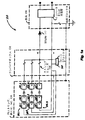
図7は、DC電力システムにおけるホームランケーブルまたはその他の適切な配線ラン上のアーク放電を検出する例示的なシステム700を示す。図7に示すように、システム700は、複数の電流センサ702.1〜702.4、整流器704、フィルタ706、比較器708、パルス積分器710およびプロセッサ712を含む。例えば、複数の電流センサ702.1〜702.4は、それぞれ、DC電力システムの電流出力をモニタする変流器として実行することができる。システム700の動作は、システム700が4つの電流センサ702.1〜702.4を使用して動作することを除いて、システム200(図2参照)の動作と同様である。図7は、システム700が説明の目的のために4つの電流システム702.1〜702.4を含むことを示しており、システム700は、代替的に、任意のその他の適切な数のこのような電流センサを含むことができることに留意されたい。
FIG. 7 illustrates an example system 700 for detecting arcing on a home run cable or other suitable wiring run in a DC power system. As shown in FIG. 7, the system 700 includes a plurality of current sensors 702.1 to 702.4, a rectifier 704, a filter 706, a
システム700は、下記の例証的な説明および図7を参照してさらに理解されよう。この例において、4つの電流センサ702.1〜702.4は並列に接続されて、合計12本またはその他の適切な数のこのようなPVストリングを含むことのできるホームランケーブル上で4つのPVストリングをそれぞれモニタする。さらに、この例において、直列アーク放電は約3アンペア(AC)の電流変動を有するホームランケーブル上に生じると想定される。同じインピーダンスと仮定すると、ホームランケーブル上の12本のPVストリングのそれぞれは、それゆえ、約3/12または0.25アンペア(AC)のアーク電流を受け取る。それぞれの電流センサ702.1〜702.4によってモニタされる4つのPVストリングに関して、電流センサ702.1によってモニタされる第1のPVストリングは、約0.25アンペア(AC)のアーク電流I1を受け取り、電流センサ702.2によってモニタされる第2のPVストリングは、約0.25アンペア(AC)のアーク電流I2を受け取り、電流センサ702.3によってモニタされる第3のPVストリングは、約0.25アンペア(AC)のアーク電流I3を受け取り、電流センサ702.4によってモニタされる第4のPVストリングは、約0.25アンペア(AC)のアーク電流I4を受け取る。しかし、4つの電流センサ702.1〜702.4が並列に接続されるので、全波整流器704に提供される結合されたアーク電流は、約4*0.25または1アンペア(AC)である。 System 700 will be further understood with reference to the following illustrative description and FIG. In this example, four current sensors 702.1-702.4 are connected in parallel and four PV strings on a home run cable that can include a total of twelve or other suitable number of such PV strings. Are monitored individually. Further, in this example, it is assumed that series arcing occurs on a home run cable with a current variation of about 3 amps (AC). Assuming the same impedance, each of the 12 PV strings on the home run cable therefore receives an arc current of about 3/12 or 0.25 amps (AC). For the four PV strings monitored by each current sensor 702.1-702.4, the first PV string monitored by current sensor 702.1 is about 0.25 amps (AC) arc current I 1. And a second PV string monitored by current sensor 702.2 receives an arc current I 2 of about 0.25 amps (AC) and a third PV string monitored by current sensor 702.3 is A fourth PV string that receives an arc current I 3 of about 0.25 amps (AC) and monitored by current sensor 702.4 receives an arc current I 4 of about 0.25 amps (AC). However, since the four current sensors 702.1-702.4 are connected in parallel, the combined arc current provided to the full wave rectifier 704 is about 4 * 0.25 or 1 Ampere (AC). .
システム700(図7参照)内の全波整流器704にレベルの上昇したアーク電流を提供するために、並列に接続された4つの電流センサ702.1〜702.4を用いることにより、ホームランケーブルまたはその他の適切な配線ラン上の直列アーク放電の検出の改善が達成できる。図7は並列に接続された4つの電流センサ702.1〜702.4を示しているが、任意の適切の数のこのような電流センサが、並列、直列、または並列/直列相互接続のその他の適切な組み合わせで接続され得ることに留意されたい。約3アンペア(AC)の電流変動を有するこのような直列アーク放電が、説明目的のために上記で説明されたが、システム700がその他の適切なレベルの直列アーク放電を検出するのに用いることができることにさらに留意されたい。 By using four current sensors 702.1-702.4 connected in parallel to provide a full level rectifier 704 in full-wave rectifier 704 in system 700 (see FIG. 7), a home run cable or Improved detection of series arcing on other suitable wiring runs can be achieved. Although FIG. 7 shows four current sensors 702.1-702.4 connected in parallel, any suitable number of such current sensors can be connected in parallel, in series, or in other parallel / series interconnects. Note that they can be connected in any suitable combination. Although such a series arc discharge having a current variation of about 3 amps (AC) has been described above for illustrative purposes, the system 700 uses it to detect other suitable levels of series arc discharge. Note further that
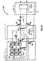
図8は、DC電力システムにおける、ホームランケーブルまたはその他の適切な配線ラン上のアーク放電を検出する別の例示的なシステム800を示す。システム700(図7参照)の代替的な実施形態であるシステム800は、複数のPVストリングを有するPVシステムに用いられるアーク故障検出デバイスにおいてアークノイズ伝搬の影響を削減するのに使用できる。例えば、アーク放電が、複数のPVストリングのうちの最初の1つ(第1のPVストリング)に対応する導線上の場所で生じる場合、第1のPVストリング上のアーク放電のものと同様のアーク電流の特徴(例えば直列アーク放電)を有するアーク放電は、第1のPVストリングに隣接する少なくとも1つのPVストリングに対応する導線上の場所で生じることができる。隣接するPVストリングに対応する導線上で生じ得るこのようなアーク放電は(このようなアーク放電を、本明細書では「隣接する導線のクロストーク」とも称する)、一般にPVシステム内のインピーダンスの分配によるものであり、かつ、それぞれのPVストリングのインピーダンスに応じて、振幅および位相シフトが減少したものと通常は特徴付けられる。図8のシステム800は、PVシステム内のこのような隣接する導線のクロストークを効果的に相殺する(打ち消す)ように構成される。この方法において、PVストリングレベルで、直列アーク放電などのアーク放電を検出するアーク故障検出デバイスの機能を改善することができる。 FIG. 8 illustrates another exemplary system 800 for detecting arcing on a home run cable or other suitable wiring run in a DC power system. System 800, an alternative embodiment of system 700 (see FIG. 7), can be used to reduce the effects of arc noise propagation in arc fault detection devices used in PV systems with multiple PV strings. For example, if the arc discharge occurs at a location on the conductor corresponding to the first one of the PV strings (the first PV string), an arc similar to that of the arc discharge on the first PV string An arc discharge having a current characteristic (eg, a series arc discharge) can occur at a location on the conductor corresponding to at least one PV string adjacent to the first PV string. Such arcing that can occur on conductors corresponding to adjacent PV strings (such arcing is also referred to herein as “adjacent conductor crosstalk”) is generally a distribution of impedance within a PV system. And is usually characterized as having a reduced amplitude and phase shift depending on the impedance of each PV string. The system 800 of FIG. 8 is configured to effectively cancel (cancele) such adjacent conductor crosstalk in the PV system. In this manner, the arc fault detection device's ability to detect arc discharge, such as series arc discharge, at the PV string level can be improved.
図8に示すように、システム800は、並列接続された複数の電流センサ802.1〜802.4、整流器804、フィルタ806、比較器808、パルス積分器810、およびプロセッサ812を含む。例えば、複数の電流センサ802.1〜802.4は、それぞれ、PVシステムにおけるPVストリングの電流出力をモニタする変流器として実行できる。システム800の動作は、システム700(図7参照)の動作と同様である。しかし、システム700内の電流センサ702.1〜702.4が同じ極性(例えば、同じ「N」極または「S」極)を有して構成されるのに対し、隣接するPVストリングの電流出力をモニタするシステム800内の電流センサ802.1〜802.4は、逆の極性を有して構成される。例えば、隣接するPVストリングをモニタする電流センサ802.1、802.2は、それぞれ逆のS極およびN極を有して構成することができ、隣接するPVストリングをモニタする電流センサ802.2、802.3は、それぞれ逆のN極およびS極を有して構成することができ、隣接するPVストリングをモニタする電流センサ802.3、802.4は、それぞれ逆のS極およびN極を有して構成することができる。
As shown in FIG. 8, system 800 includes a plurality of current sensors 802.1-802.4, rectifier 804, filter 806,
電流センサ802.1、802.2は、代替的にそれぞれ逆のN極およびS極を有して構成してもよく、電流センサ802.2、802.3は、代替的にそれぞれ逆のS極およびN極を有して構成してもよく、また、電流センサ802.3、802.4は、代替的にそれぞれ逆のN極およびS極を有して構成してもよいことに留意されたい。図8は、説明の目的のために4つの電流センサ802.1〜802.4を含んでおり、システム800が、PVシステムにおけるその他の適切な数のPVストリングの電流出力をモニタする、その他の適切な数のこのような電流センサを代替的に含んでもよいことにさらに留意されたい。さらに、図8は並列に接続された4つの電流センサ802.1〜802.4を示しているが、その他の適切な数のこのような電流センサは、並列、直列、または並列/直列相互接続の任意の組み合わせで接続することができる。 The current sensors 802.1, 802.2 may alternatively be configured with opposite north and south poles, respectively, and the current sensors 802.2, 802.3 may alternatively be constructed with opposite S poles. Note that the poles may be configured with poles and N poles, and the current sensors 802.3, 802.4 may alternatively be configured with opposite poles N and S, respectively. I want to be. FIG. 8 includes four current sensors 802.1-802.4 for illustrative purposes, and system 800 monitors the current output of other suitable numbers of PV strings in the PV system. Note further that an appropriate number of such current sensors may alternatively be included. Further, although FIG. 8 shows four current sensors 802.1-802.4 connected in parallel, other suitable numbers of such current sensors can be used in parallel, series, or parallel / series interconnects. Can be connected in any combination.
システム800は、以下の説明的な例および図8を参照してさらに理解されよう。第1の例において、電流センサ802.1、802.2、802.3、802.4は、合計12本またはその他の適切な数のPVストリングを含むことのできるホームランケーブル上で、それぞれ第1のPVストリング、第2のPVストリング、第3のPVストリング、および第4のPVストリングをモニタするように並列に接続される。それぞれの電流センサ802.1〜802.4によってモニタされる4つのPVストリングに関して、第1のPVストリングは第2のPVストリングにのみ隣接しており、第2のPVストリングは、第1のPVストリングと第3のPVストリングの両方に隣接しており、第3のPVストリングは、第2のPVストリングと第4のPVストリングの両方に隣接しており、第4のPVストリングは、第3のPVストリングにのみ隣接している。 System 800 will be further understood with reference to the following illustrative example and FIG. In a first example, current sensors 802.1, 802.2, 802.3, 802.4 are each first on a home run cable that can include a total of 12 or any other suitable number of PV strings. Connected in parallel to monitor the second PV string, the second PV string, the third PV string, and the fourth PV string. For the four PV strings monitored by each current sensor 802.1-802.4, the first PV string is only adjacent to the second PV string, and the second PV string is the first PV string. Adjacent to both the string and the third PV string, the third PV string is adjacent to both the second PV string and the fourth PV string, and the fourth PV string is the third PV string. Is adjacent to only the PV string.
この第1の例では、直列アーク放電は、第1のPVストリングに対応する導線上の場所で生じると想定される。このような直列アーク放電に応答して、第1のPVストリングに応答する導線は、電流センサ802.1の主巻線(L5)上へアーク電流Ip1を流し、これは電流センサ802.1の2次巻線(L6)上でアーク電流Is1となる。第1のPVストリングが、第2のPVストリングに隣接するので、隣接する導線のクロストークが第1のPVストリングと第2のPVストリングの間で発生する。このような隣接する導線のクロストークに応答して、第2のPVストリングに対応する導線は、電流センサ802.2の主巻線(L1)上にアーク電流Ip2を流し、これは、電流センサ802.2の2次巻線(L2)上でアーク電流Is2となる。 In this first example, it is assumed that the series arc discharge occurs at a location on the conductor corresponding to the first PV string. In response to such a series arc discharge, the conductor responsive to the first PV string carries an arc current I p1 on the main winding (L5) of current sensor 802.11, which is current sensor 802.1. Arc current I s1 on the secondary winding (L6). Since the first PV string is adjacent to the second PV string, adjacent conductor crosstalk occurs between the first PV string and the second PV string. In response to such adjacent conductor crosstalk, the conductor corresponding to the second PV string carries an arc current I p2 on the main winding (L1) of the current sensor 802.2, which The arc current Is2 is obtained on the secondary winding (L2) of the sensor 802.2.
電流センサ802.1および802.2は、それぞれ逆のS極およびN極を有して構成されるので、電流センサ802.1の2次巻線(L6)上のアーク電流Is1は、電流センサ802.2の2次巻線(L2)上でアーク電流Is2に対して180度の位相シフトを有する。電流センサ802.1によってモニタされる第1のPVストリング、および電流センサ802.2によってモニタされる第2のPVストリングが、実質的に同一のインピーダンスを有し、かつ、それぞれの電流センサ802.1、802.2が実質的に同じ特性を有すると仮定すると、第1のPVストリングと第2のPVストリングの間のこのような隣接するクロストークから生じるコモンモードの電流ノイズは、アーク電流Is2に対するアーク電流Is1の180度の位相シフトにより、アーク電流Is1、Is2の組み合わせにおいて(例えば、組み合わされた電流Icombinedにおいて:図8参照)、相殺されるであろう。電流センサ802.3および802.4もそれぞれ逆のS極およびN極を有して構成されるので、第3のPVストリングと第4のPVストリングの間の隣接する導線のクロストークから生じるコモンモードの電流ノイズは、同じ方法で相殺されるであろう。 Since the current sensors 802.1 and 802.2 are configured to have opposite S and N poles, respectively, the arc current Is1 on the secondary winding (L6) of the current sensor 802.1 It has a phase shift of 180 degrees with respect to the arc current Is2 on the secondary winding (L2) of the sensor 802.2. The first PV string monitored by current sensor 802.1 and the second PV string monitored by current sensor 802.2 have substantially the same impedance and each current sensor 802. 1 and 802.2 have substantially the same characteristics, the common mode current noise resulting from such adjacent crosstalk between the first PV string and the second PV string is the arc current I the 180 degree phase shift of the arc current I s1 against s2, in combination with the arc current I s1, I s2 (e.g., in a combined current I the combined: see FIG. 8), it will be canceled. Since current sensors 802.3 and 802.4 are also configured with opposite S and N poles respectively, the common resulting from the crosstalk of adjacent conductors between the third and fourth PV strings. The mode current noise will be canceled in the same way.
第2の例において、直列アーク放電は第2のPVストリングに対応する導線の場所で生じると想定される。このような直列アーク放電に応答して、第2のPVストリングに対応する導線は、電流センサ802.2の主巻線(L1)上にアーク電流Ip2を流し、これは電流センサ802.2の2次巻線(L2)上でアーク電流Is2となる。第2のPVストリングが第1のPVストリングに隣接するので、隣接する導線のクロストークが、第2のPVストリングと第1のPVストリングの間に生じる。第2のPVストリングと第1のPVストリングの間のこのような隣接する導線のクロストークに応答して、第1のPVストリングに対応する導線は、電流センサ802.1の主巻線(L5)上にアーク電流Ip1を流し、これは電流センサ802.1の2次巻線(L6)上でアーク電流Is1となる。さらに、第2のPVストリングは第3のPVストリングにも隣接するので、隣接する導線のクロストークが、第2のPVストリングと第3のPVストリングの間で生じる。第2のPVストリングと第3のPVストリングの間のこのような隣接する導線のクロストークに応答して、第3のPVストリングに対応する導線は、電流センサ802.3の主巻線(L3)上にアーク電流Ip3を流し、これは電流センサ802.3の2次巻線(L4)上でアーク電流Is3となる。 In the second example, it is assumed that the series arc discharge occurs at the location of the conductor corresponding to the second PV string. In response to such a series arc discharge, the conductor corresponding to the second PV string carries an arc current I p2 on the main winding (L1) of the current sensor 802.2, which is current sensor 802.2. Arc current Is2 on the secondary winding (L2). Since the second PV string is adjacent to the first PV string, adjacent conductor crosstalk occurs between the second PV string and the first PV string. In response to such adjacent conductor crosstalk between the second PV string and the first PV string, the conductor corresponding to the first PV string is connected to the main winding (L5 of current sensor 802.1). ) Causes an arc current I p1 to flow, which becomes the arc current I s1 on the secondary winding (L6) of the current sensor 802.1. Further, since the second PV string is also adjacent to the third PV string, adjacent conductor crosstalk occurs between the second PV string and the third PV string. In response to such adjacent conductor crosstalk between the second PV string and the third PV string, the conductor corresponding to the third PV string is connected to the main winding (L3 of the current sensor 802.3). ), An arc current I p3 is caused to flow, and this becomes the arc current Is3 on the secondary winding (L4) of the current sensor 802.3.
電流センサ802.2および802.1が、それぞれ逆のN極およびS極を有して構成されるので、電流センサ802.2の2次巻線(L2)上のアーク電流Is2は、電流センサ802.1の2次巻線(L6)上のアーク電流Is1に対して180度の位相シフトを有する。第1の例と同様に、第1のPVストリングおよび第2のPVストリングが実質的に同一のインピーダンスを有し、かつそれぞれの電流センサ802.1、802.2が実質的に同一の特性を有すると仮定すると、第2のPVストリングと第1のPVストリングの間の隣接する導線のクロストークによって生じるコモンモードの電流ノイズは、アーク電流Is1に対するアーク電流Is2の180度の位相シフトにより、アーク電流Is2、Is1の組み合わせにおいて(すなわち、組み合わされた電流Icombinedにおいて:図8参照)相殺されるであろう。 Since current sensors 802.2 and 802.1 are configured with opposite north and south poles, respectively, arc current Is2 on the secondary winding (L2) of current sensor 802.2 is the current It has a 180 degree phase shift with respect to the arc current Is1 on the secondary winding (L6) of sensor 802.12. Similar to the first example, the first PV string and the second PV string have substantially the same impedance, and the respective current sensors 802.1, 802.2 have substantially the same characteristics. Assuming that the common mode current noise caused by the adjacent conductor crosstalk between the second PV string and the first PV string is due to the 180 degree phase shift of the arc current Is2 relative to the arc current Is1, the arc It will cancel out in the combination of currents I s2 and I s1 (ie in combined current I combined : see FIG. 8).
同様に、電流センサ802.2および802.3がそれぞれ逆のN極およびS極を有して構成されるので、電流センサ802.2の2次巻線(L2)上のアーク電流Is2は、電流センサ802.3の2次巻線(L4)上のアーク電流Is3に対して180度の位相シフトを有する。第2のPVストリングおよび第3のPVストリングが実質的に同じインピーダンスを有し、かつ、それぞれの電流センサ802.2、802.3が実質的に同じ特性を有すると仮定すると、第2のPVストリングと第3のPVストリングの間のこのような隣接する導線のクロストークから生じるコモンモードの電流ノイズも、アーク電流Is3に対するアーク電流Is2の180度の位相シフトにより、アーク電流Is2、Is3の組み合わせにおいて(すなわち、結合された電流Icombinedにおいて:図8参照)相殺されるであろう。電流センサ802.3および802.2が逆の極性(S極、N極)を有して構成され、電流センサ802.3および802.4も逆の極性(S極、N極)を有して構成されるので、第3のPVストリングと第2のPVストリングの間、および第3のPVストリングと第4のPVストリングの間の隣接する導線のクロストークから生じるコモンモードの電流ノイズは、同じ方法で相殺されるであろう。 Similarly, since current sensors 802.2 and 802.3 are configured with opposite north and south poles, respectively, arc current Is2 on the secondary winding (L2) of current sensor 802.2 is , Having a 180 degree phase shift with respect to the arc current Is3 on the secondary winding (L4) of the current sensor 802.3. Assuming that the second PV string and the third PV string have substantially the same impedance and that the respective current sensors 802.2, 802.3 have substantially the same characteristics, the second PV string the string and such a current common mode noise resulting from crosstalk between adjacent conductors also phase shift of 180 degrees of arc current I s2 for the arc current I s3 between the third PV string, arc current I s2, In the combination of I s3 (ie in the combined current I combined : see FIG. 8) it will cancel. Current sensors 802.3 and 802.2 are configured with opposite polarities (S pole, N pole), and current sensors 802.3 and 802.4 are also configured with opposite polarities (S pole, N pole). The common mode current noise resulting from the crosstalk of adjacent conductors between the third PV string and the second PV string and between the third PV string and the fourth PV string is Will be offset in the same way.
PVシステムにおいて隣接するPVストリングの電流出力をモニタするシステム800(図8参照)内の電流センサ802.1〜802.4が、隣接するPVストリング間の隣接する導線のクロストークを効果的に相殺するように、逆の極性を有して構成できることを上記で説明した。一実施形態では、PVシステムにおいて隣接するPVストリグの電流出力をモニタする電流センサ802.1〜802.4は、代替的に同じ極性(例えば同じN極またはS極)を有して構成してもよく、それぞれの隣接するPVストリングに対応する導線は、反対方向に電流を提供するように構成および配置してもよい。この方法で、隣接するPVストリング間の隣接する導線のクロストークによって生じるコモンモードの電流ノイズも、方向性の対向する電流を結果的に組み合わせることで効果的に相殺できる。 Current sensors 802.1-802.4 in a system 800 (see FIG. 8) that monitors the current output of adjacent PV strings in a PV system effectively offsets adjacent conductor crosstalk between adjacent PV strings. As described above, it has been described above that it can be configured with the opposite polarity. In one embodiment, current sensors 802.1-802.4 that monitor the current output of adjacent PV strigs in a PV system may alternatively be configured with the same polarity (eg, the same N or S pole). Alternatively, the conductors corresponding to each adjacent PV string may be configured and arranged to provide current in the opposite direction. In this manner, common mode current noise caused by crosstalk between adjacent conductors between adjacent PV strings can also be effectively canceled out by combining the resulting directional opposing currents.
本明細書において説明した1つまたは複数の実施形態が、ソフトウェアおよび/またはハードウェアの多種多様な形態で実行できることが明らかとなろう。例えば、本明細書において説明した1つまたは複数の実施形態は、1つまたは複数のコンピュータデバイス、ハードウェアプロセッサ、および/または同様のもののうちの適切な構成を含んで、本明細書において説明した一部または全部のシステムおよび/または方法を実行および/またはサポートすることができる。さらに、1つまたは複数のコンピュータデバイス、プロセッサ、デジタル信号プロセッサ等は、本明細書において説明したシステムおよび方法を実行するようにプログラムおよび/または構成することができる。 It will be apparent that one or more of the embodiments described herein can be implemented in a wide variety of forms of software and / or hardware. For example, one or more embodiments described herein include any suitable configuration of one or more computing devices, hardware processors, and / or the like described herein. Some or all systems and / or methods may be implemented and / or supported. Further, one or more computing devices, processors, digital signal processors, etc. may be programmed and / or configured to perform the systems and methods described herein.
DC電力システムにおいてアーク放電を検出する、上記のシステムおよび方法の修正形態及び変形形態が、本明細書において開示した発明の概念から逸脱することなく実行できることを当業者は理解するであろう。従って、本発明は、添付の特許請求の範囲の範囲および精神によって限定される場合を除いて、限定的に解釈されるべきでない。
Those skilled in the art will appreciate that modifications and variations of the above-described systems and methods for detecting arcing in DC power systems can be implemented without departing from the inventive concepts disclosed herein. Accordingly, the invention should not be construed in a limiting sense, except as limited by the scope and spirit of the appended claims.
Claims (21)
少なくとも2つの逆の極性を有する電流センサによって少なくとも2つの電流出力をそれぞれ監視し、前記少なくとも2つの電流出力は、前記DC電力システム内の少なくとも2つの隣接する導体上の各電流センサによる監視のために提供され、
前記少なくとも2つの電流出力を結合し、結合された電流出力を提供し、
時間上の前記結合された電流出力の少なくとも1つの変化(di/dt)に応答して1つまたは複数のパルスを生成し、
プロセッサにより、前記DC電力システム内のアーク放電の存在を判定するように前記それぞれのパルスを処理し、
前記プロセッサにより、前記DC電力システム内のアーク放電の存在を示す出力を生成する、方法。 A method for detecting arcing in a DC power system comprising:
At least two current outputs are respectively monitored by current sensors having at least two opposite polarities, the at least two current outputs being monitored by each current sensor on at least two adjacent conductors in the DC power system Provided to
Combining the at least two current outputs to provide a combined current output;
Generating one or more pulses in response to at least one change (di / dt) in the combined current output over time;
A processor to process each of the pulses to determine the presence of arcing in the DC power system;
A method by which the processor generates an output indicative of the presence of arcing in the DC power system.
プロセッサにより、少なくとも1つの予め決められた時間間隔におけるパルスの数をカウントし、当該予め決められた時間間隔のパルスカウントを提供し、
前記プロセッサにより、前記予め決められた時間間隔における前記それぞれのパルスの幅の変動を測定し、
前記プロセッサにより、前記パルスカウントに対する前記それぞれのパルスの幅の変動の第1の比を算出し、
前記プロセッサにより、前記第1の比に少なくとも一部に基づき、前記DC電力システム内のアーク放電の存在を判定し、
前記プロセッサにより、前記DC電力システム内のアーク放電の存在を示す出力を生成する、請求項1に記載の方法。 Each of the pulses has an associated width, and the method further comprises:
The processor counts the number of pulses in at least one predetermined time interval and provides a pulse count for the predetermined time interval;
The processor measures the variation in width of each of the pulses in the predetermined time interval;
Calculating, by the processor, a first ratio of variations in the width of each of the pulses to the pulse count;
Determining, by the processor, the presence of arcing in the DC power system based at least in part on the first ratio;
The method of claim 1, wherein the processor generates an output that indicates the presence of arcing in the DC power system.
請求項2に記載の方法。 Counting the number of pulses includes counting the number of pulses at each of a plurality of predetermined time intervals so as to provide a pulse count for each predetermined time interval, Measuring the variation in the width of the pulse comprises measuring the variation in the width of the respective pulse in the respective predetermined time interval;
The method of claim 2.
をさらに含む、請求項2に記載の方法。 The method of claim 2, further comprising measuring, by the processor, a modulation of the width of each of the pulses in the predetermined time interval.
をさらに含む、請求項6に記載の方法。 7. The method of claim 6, further comprising: calculating, by the processor, a second ratio of the variation in the width of the respective pulse to the modulation of the width of the respective pulse.
請求項7に記載の方法。 Determining the presence of arcing includes determining the presence of arcing in the DC power system based at least in part on the first ratio and the second ratio;
The method of claim 7.
をさらに含む、請求項7に記載の方法。 The method of claim 7, further comprising measuring, by the processor, a variation in the pulse count during the predetermined time interval.
をさらに含む、請求項12に記載の方法。 The processor calculates one or more of a variation in the pulse count versus a third ratio of the pulse count and a variation in the width of the respective pulse versus a fourth ratio of the width of the respective pulse. The method of claim 12 further comprising:
少なくとも2つの電流出力をそれぞれモニタするように動作し、結合された電流出力を提供するように構成および配置される少なくとも2つの電流センサであって、前記少なくとも2つの電流センサが逆の極性を有し、前記少なくとも2つの電流出力が、前記DC電力システムにおいて、少なくとも2つの隣接する導体上の前記それぞれの電流センサによるモニタのために提供される、電流センサと、
時間上で前記結合された電流出力における少なくとも1つの変化(di/dt)に応答して、1つまたは複数のパルスを生成するように動作する比較器と、
前記DC電力システムにおけるアーク放電の存在を判定し、前記DC電力システムにおけるアーク放電の存在を示す出力を生成するように、前記それぞれのパルスを処理するように動作するプロセッサと
を含む、システム。 A system for detecting arcing in a DC power system,
At least two current sensors configured and arranged to each monitor at least two current outputs and provide a combined current output, the at least two current sensors having opposite polarities; A current sensor, wherein the at least two current outputs are provided for monitoring by the respective current sensors on at least two adjacent conductors in the DC power system;
A comparator operable to generate one or more pulses in response to at least one change (di / dt) in the combined current output over time;
A processor operable to determine the presence of arcing in the DC power system and to process the respective pulses to produce an output indicative of the presence of arcing in the DC power system.
少なくとも2つの電流出力をそれぞれモニタするように動作し、結合された電流出力を提供するように構成および配置される少なくとも2つの電流センサであって、前記少なくとも2つの電流出力が、前記DC電力システムにおいて、少なくとも2つの隣接する導体上の前記それぞれの電流センサによるモニタのために提供され、前記少なくとも2つの隣接する導体が、反対の方向で、前記少なくとも2つの電流出力を提供するように構成および配置される、電流センサと、
時間上で前記結合された電流出力における少なくとも1つの変化(di/dt)に応答して、1つまたは複数のパルスを生成するように動作する比較器と、
前記DC電力システムにおけるアーク放電の存在を判定し、前記DC電力システムにおけるアーク放電の存在を示す出力を生成するように、前記それぞれのパルスを処理するように動作するプロセッサと
を含む、システム。
A system for detecting arcing in a DC power system,
At least two current sensors configured and arranged to each monitor at least two current outputs and provide a combined current output, wherein the at least two current outputs are the DC power system Wherein the at least two adjacent conductors are provided for monitoring by the respective current sensors on at least two adjacent conductors, wherein the at least two adjacent conductors are configured to provide the at least two current outputs in opposite directions and A current sensor disposed;
A comparator operable to generate one or more pulses in response to at least one change (di / dt) in the combined current output over time;
A processor operable to determine the presence of arcing in the DC power system and to process the respective pulses to produce an output indicative of the presence of arcing in the DC power system.
Applications Claiming Priority (2)
| Application Number | Priority Date | Filing Date | Title |
|---|---|---|---|
| US14/138,575 US9634479B2 (en) | 2012-11-16 | 2013-12-23 | Noise propagation immunity of a multi-string arc fault detection device |
| US14/138,575 | 2013-12-23 |
Publications (2)
| Publication Number | Publication Date |
|---|---|
| JP2015155889A true JP2015155889A (en) | 2015-08-27 |
| JP2015155889A5 JP2015155889A5 (en) | 2018-02-01 |
Family
ID=52146278
Family Applications (1)
| Application Number | Title | Priority Date | Filing Date |
|---|---|---|---|
| JP2014258291A Pending JP2015155889A (en) | 2013-12-23 | 2014-12-22 | Improved noise propagation immunity of a multi-string arc fault detection device |
Country Status (4)
| Country | Link |
|---|---|
| EP (1) | EP2887082B1 (en) |
| JP (1) | JP2015155889A (en) |
| KR (1) | KR102210973B1 (en) |
| CN (1) | CN104730433B (en) |
Cited By (1)
| Publication number | Priority date | Publication date | Assignee | Title |
|---|---|---|---|---|
| WO2017048240A1 (en) * | 2015-09-15 | 2017-03-23 | Intel Corporation | Silicon controlled rectifier with propagating trigger |
Families Citing this family (8)
| Publication number | Priority date | Publication date | Assignee | Title |
|---|---|---|---|---|
| CN105067931A (en) * | 2015-08-19 | 2015-11-18 | 珠海格力电器股份有限公司 | Series fault arc detection circuit |
| KR101723831B1 (en) | 2016-07-22 | 2017-04-06 | 지투파워 (주) | Solar power generating system having arc detector function of pv modules |
| CN106683318A (en) * | 2017-03-21 | 2017-05-17 | 北京腾锐视讯科技有限公司 | Fault arc fire alarm detector |
| CN106950476A (en) * | 2017-03-31 | 2017-07-14 | 北京腾锐视讯科技有限公司 | A kind of fault electric arc detection sensor of some face installation parallel with detected wire |
| CN107086855B (en) * | 2017-04-25 | 2018-10-30 | 西安交通大学 | The photovoltaic system fault arc detection method of more time-frequency characteristics is merged in a kind of machine learning |
| CN111512511B (en) * | 2017-12-29 | 2021-08-20 | 华为技术有限公司 | Method and device for processing direct current arc |
| US10914779B2 (en) * | 2018-05-07 | 2021-02-09 | Schneider Electric USA, Inc. | Arc fault detection using time segmented captures |
| CN113807018A (en) * | 2020-12-28 | 2021-12-17 | 南京航空航天大学 | Chaotic quantum cuckoo search optimization method |
Citations (8)
| Publication number | Priority date | Publication date | Assignee | Title |
|---|---|---|---|---|
| JPH03134999A (en) * | 1989-10-20 | 1991-06-07 | Japan Atom Energy Res Inst | Arc power source protecting circuit for ion source |
| JP2001289900A (en) * | 2000-04-11 | 2001-10-19 | Tempearl Ind Co Ltd | Insulation deterioration detecting circuit and device using it |
| US20010040458A1 (en) * | 1998-12-21 | 2001-11-15 | Macbeth Bruce F. | Arc fault circuit detector device detecting pulse width modulation of arc noise |
| US20060109009A1 (en) * | 2004-11-19 | 2006-05-25 | Esw-Extel Systems Wedel Gesellschaft Fuer Ausruestung Mbh | Method and device for the detection of fault current arcing in electric circuits |
| US20090161270A1 (en) * | 2007-12-19 | 2009-06-25 | Beatty Jr William E | Industrial arc fault circuit interrupter and method of detecting arcing conditions |
| US20100027176A1 (en) * | 2008-08-01 | 2010-02-04 | Kawate Keith W | Arc fault detection apparatus employing a comparator with a continuously variable threshold |
| US20120112760A1 (en) * | 2010-11-09 | 2012-05-10 | Solaredge Technologies Ltd. | Arc Detection and Prevention in a Power Generation System |
| US8218274B2 (en) * | 2009-12-15 | 2012-07-10 | Eaton Corporation | Direct current arc fault circuit interrupter, direct current arc fault detector, noise blanking circuit for a direct current arc fault circuit interrupter, and method of detecting arc faults |
Family Cites Families (8)
| Publication number | Priority date | Publication date | Assignee | Title |
|---|---|---|---|---|
| SE515388C2 (en) * | 1995-09-14 | 2001-07-23 | Abb Research Ltd | Device for sensing electrical discharges in a sample object |
| US6392401B1 (en) * | 1998-06-05 | 2002-05-21 | Chathan M. Cooke | Closely-coupled multiple-winding magnetic induction-type sensor |
| US7408750B2 (en) * | 2004-09-09 | 2008-08-05 | Sensata Technologies Massachusetts, Inc. | Methods of detecting arc faults characterized by consecutive periods of arcing |
| US7190561B2 (en) * | 2004-09-09 | 2007-03-13 | Sensata Technologies, Inc. | Apparatus for detecting arc faults |
| WO2011011711A2 (en) * | 2009-07-23 | 2011-01-27 | Enphase Energy, Inc. | Method and apparatus for detection and control of dc arc faults |
| US20110090607A1 (en) * | 2009-10-20 | 2011-04-21 | Luebke Charles J | String and system employing direct current electrical generating modules and a number of string protectors |
| KR20120032925A (en) * | 2010-09-29 | 2012-04-06 | 삼성전자주식회사 | Electric apparatus, electric apparatus system and method for detecting arc fault thereof |
| DE102012104314B4 (en) * | 2012-05-18 | 2014-04-10 | Sma Solar Technology Ag | Method and device for locating and extinguishing an arc |
-
2014
- 2014-12-22 JP JP2014258291A patent/JP2015155889A/en active Pending
- 2014-12-22 EP EP14199638.9A patent/EP2887082B1/en active Active
- 2014-12-23 KR KR1020140186751A patent/KR102210973B1/en active IP Right Grant
- 2014-12-23 CN CN201410806996.5A patent/CN104730433B/en active Active
Patent Citations (9)
| Publication number | Priority date | Publication date | Assignee | Title |
|---|---|---|---|---|
| JPH03134999A (en) * | 1989-10-20 | 1991-06-07 | Japan Atom Energy Res Inst | Arc power source protecting circuit for ion source |
| US20010040458A1 (en) * | 1998-12-21 | 2001-11-15 | Macbeth Bruce F. | Arc fault circuit detector device detecting pulse width modulation of arc noise |
| JP2001289900A (en) * | 2000-04-11 | 2001-10-19 | Tempearl Ind Co Ltd | Insulation deterioration detecting circuit and device using it |
| US20060109009A1 (en) * | 2004-11-19 | 2006-05-25 | Esw-Extel Systems Wedel Gesellschaft Fuer Ausruestung Mbh | Method and device for the detection of fault current arcing in electric circuits |
| US20090161270A1 (en) * | 2007-12-19 | 2009-06-25 | Beatty Jr William E | Industrial arc fault circuit interrupter and method of detecting arcing conditions |
| US20100027176A1 (en) * | 2008-08-01 | 2010-02-04 | Kawate Keith W | Arc fault detection apparatus employing a comparator with a continuously variable threshold |
| US8218274B2 (en) * | 2009-12-15 | 2012-07-10 | Eaton Corporation | Direct current arc fault circuit interrupter, direct current arc fault detector, noise blanking circuit for a direct current arc fault circuit interrupter, and method of detecting arc faults |
| US20120112760A1 (en) * | 2010-11-09 | 2012-05-10 | Solaredge Technologies Ltd. | Arc Detection and Prevention in a Power Generation System |
| JP2012112937A (en) * | 2010-11-09 | 2012-06-14 | Solaredge Technologies Ltd | Arc detection and prevention in power generation system |
Cited By (1)
| Publication number | Priority date | Publication date | Assignee | Title |
|---|---|---|---|---|
| WO2017048240A1 (en) * | 2015-09-15 | 2017-03-23 | Intel Corporation | Silicon controlled rectifier with propagating trigger |
Also Published As
| Publication number | Publication date |
|---|---|
| CN104730433B (en) | 2018-12-28 |
| KR20150073870A (en) | 2015-07-01 |
| EP2887082A1 (en) | 2015-06-24 |
| EP2887082B1 (en) | 2019-09-18 |
| KR102210973B1 (en) | 2021-02-02 |
| CN104730433A (en) | 2015-06-24 |
Similar Documents
| Publication | Publication Date | Title |
|---|---|---|
| KR101991139B1 (en) | Systems and methods of discriminating dc arcs and load switching noise | |
| JP2015155889A (en) | Improved noise propagation immunity of a multi-string arc fault detection device | |
| US9634479B2 (en) | Noise propagation immunity of a multi-string arc fault detection device | |
| US9502885B2 (en) | Home run arc detection at the photovoltaic string level using multiple current sensors | |
| AU2010282204B2 (en) | Method for detecting arcs in photovoltaic systems and such a photovoltaic system | |
| EP2514057B1 (en) | Direct current arc fault circuit interrupter, direct current arc fault detector, and method of detecting arc faults | |
| US10432139B2 (en) | Electric arc detection in photovoltaic installations | |
| CN109417285B (en) | Direct current electric loop protection device and arc detection method | |
| JP2014531022A (en) | Method and apparatus for detecting arcs in DC circuits | |
| JP6298663B2 (en) | Solar cell string level home run arc discharge detection using multiple current sensors | |
| US11152776B2 (en) | Overcurrent and short-circuit detector | |
| CN102539997A (en) | Method and device for detecting arc faults in an alternating current network | |
| US11067638B2 (en) | Method of and system for detecting a serial arc fault in a power circuit | |
| KR101464246B1 (en) | Arc detection breaker using ZCT | |
| JP2001289900A (en) | Insulation deterioration detecting circuit and device using it | |
| KR102519681B1 (en) | Apparatus and method for detecting arc fault using weighted sum of arc noise signal | |
| JP6958146B2 (en) | Arc detector | |
| JP2003125532A (en) | Tracking breaker | |
| JP2001289903A (en) | Insulation deterioration detecting circuit and device using this circuit |
Legal Events
| Date | Code | Title | Description |
|---|---|---|---|
| A521 | Request for written amendment filed |
Free format text: JAPANESE INTERMEDIATE CODE: A523 Effective date: 20171218 |
|
| A621 | Written request for application examination |
Free format text: JAPANESE INTERMEDIATE CODE: A621 Effective date: 20171218 |
|
| A871 | Explanation of circumstances concerning accelerated examination |
Free format text: JAPANESE INTERMEDIATE CODE: A871 Effective date: 20171218 |
|
| A975 | Report on accelerated examination |
Free format text: JAPANESE INTERMEDIATE CODE: A971005 Effective date: 20180223 |
|
| A131 | Notification of reasons for refusal |
Free format text: JAPANESE INTERMEDIATE CODE: A131 Effective date: 20180306 |
|
| A02 | Decision of refusal |
Free format text: JAPANESE INTERMEDIATE CODE: A02 Effective date: 20181023 |