JP2015155254A - Rear sub-frame structure of automobile - Google Patents
Rear sub-frame structure of automobile Download PDFInfo
- Publication number
- JP2015155254A JP2015155254A JP2014030775A JP2014030775A JP2015155254A JP 2015155254 A JP2015155254 A JP 2015155254A JP 2014030775 A JP2014030775 A JP 2014030775A JP 2014030775 A JP2014030775 A JP 2014030775A JP 2015155254 A JP2015155254 A JP 2015155254A
- Authority
- JP
- Japan
- Prior art keywords
- vehicle body
- side members
- cross member
- pair
- link
- Prior art date
- Legal status (The legal status is an assumption and is not a legal conclusion. Google has not performed a legal analysis and makes no representation as to the accuracy of the status listed.)
- Granted
Links
Images


Abstract
Description
本発明は、車体のキックアップ部及びリヤフレームに取り付けられ、マルチリンク式のリヤサスペンション装置の一部となる自動車のリヤサブフレーム構造に関する。 The present invention relates to a rear sub-frame structure for an automobile that is attached to a kick-up portion and a rear frame of a vehicle body and is a part of a multi-link type rear suspension device.
自動車の組立において、リヤサスペンションを構成するリンクやアームをリヤサブフレーム構造に取り付け、さらに、リヤサブフレーム構造を車体後部に下方から取り付けることが知られている。 In assembling an automobile, it is known that a link and an arm constituting a rear suspension are attached to a rear subframe structure, and further, a rear subframe structure is attached to a rear portion of a vehicle body from below.
リヤサブフレーム構造としては、例えば、サイドメンバ、フロントメンバ及びリヤメンバにより構成されたサスペンションクロスメンバと、このサスペンションクロスメンバにより支持されたサスペンションリンクとを備えたマルチリンク式の自動車のリヤサスペンション装置におけるリヤサブフレーム構造が知られている(例えば、特許文献1参照)。この特許文献1のリヤサスペンション装置では、車体の左右両側において前後方向に延びる一対のサイドクロスメンバの上面側に、サスペンションリンクの車体側の端部が取り付けられる取付部が設けられている。
As a rear subframe structure, for example, a rear in a rear suspension device of a multilink type automobile including a suspension cross member constituted by a side member, a front member and a rear member, and a suspension link supported by the suspension cross member. A subframe structure is known (see, for example, Patent Document 1). In the rear suspension device of
上述の特許文献1に記載されているような従来の構造において、サイドクロスメンバにサスペンションリンクの取付部を設けた場合、車体前後方向に延びるサイドクロスメンバに対して、車幅方向に延びるサスペンションリンクから、サイドクロスメンバの長手方向に直交する方向の力が加えられる。これによりサイドクロスメンバに曲げ変形やねじれ変形が生じ、ドライバの運転操作に対する応答性や剛性感が悪化することを防止するために、従来の構造においては、サスペンションリンクの取付部を剛性の高い位置(例えばサイドクロスメンバとフロントメンバ又はリヤメンバとの連結部近傍)に設けたり、サスペンションリンクの取付部近傍に補強部材を設けたりしている。この場合、サスペンションリンクの取付位置に制約が生じたり、リヤサブフレーム構造の重量増を招くことがある。
In the conventional structure as described in
本発明は、上述した従来技術の問題点を解決するためになされたものであり、補強による重量の増大やサスペンションリンクの取付位置の制限を招くことなく、サスペンションリンクから加えられる力に対する剛性を向上させることができる自動車のリヤサブフレーム構造を提供することを目的とする。 The present invention has been made to solve the above-mentioned problems of the prior art, and improves the rigidity against the force applied from the suspension link without causing an increase in weight due to reinforcement or a restriction on the mounting position of the suspension link. It is an object of the present invention to provide a rear subframe structure for an automobile that can be made to operate.
上記の目的を達成するために、本発明の自動車のリヤサブフレーム構造は、車体のキックアップ部及びリヤフレームに取り付けられ、マルチリンク式のリヤサスペンション装置の一部となる自動車のリヤサブフレーム構造であって、車幅方向左右両側においてそれぞれ車体前後方向に延び、その前端部が車体のキックアップ部の前部に連結される一対のサイドメンバと、一対のサイドメンバを互いに連結するように車幅方向に延び、その左右両端部がサイドメンバよりも高い位置で車体のリヤフレームに連結される前クロスメンバと、一対のサイドメンバの後端部においてこれらのサイドメンバを互いに連結するように車幅方向に延び、その左右両端部が車体のキックアップ部の後方においてサイドメンバよりも高い位置で車体のリヤフレームに連結される後クロスメンバと、を備え、マルチリンク式のリヤサスペンション装置が備えるサスペンションリンクの内、1組の左右一対のサスペンションリンクの車体側の端部が取り付けられる取付部は、一対のサイドメンバの前端部と前クロスメンバとの間において、一対のサイドメンバの上面に配置され、一対のサイドメンバは、そのサイドメンバの長手方向に直交する断面の幅が、サイドメンバの前後端から取付部に向かって拡大するように形成されていることを特徴とする。
このように構成された本発明においては、サイドメンバは、その長手方向に直交する断面の幅が、サイドメンバの前後端から取付部に向かって拡大するように形成されているので、取付部の近傍におけるサイドメンバの曲げ剛性やねじり剛性を向上させることができ、これにより、サスペンションリンクから取付部を介してサイドメンバに加えられる力に対するサイドメンバの剛性を向上させることができる。
また、追加の補強部材を設ける必要がなく、前クロスメンバや後クロスメンバとサイドメンバとの連結部の近傍に取付部を設ける必要もないので、補強による重量の増大やサスペンションリンクの取付位置の制限を招くことなく、サスペンションリンクから加えられる力に対するサイドメンバの剛性を向上させることができる。
In order to achieve the above object, a rear subframe structure for an automobile according to the present invention is attached to a kick-up portion of a vehicle body and a rear frame, and forms a part of a multi-link type rear suspension device. A pair of side members that extend in the longitudinal direction of the vehicle body on both the left and right sides in the vehicle width direction and whose front end portions are coupled to the front portion of the kick-up portion of the vehicle body, and the pair of side members that are coupled to each other. The front cross member that extends in the width direction and whose left and right ends are connected to the rear frame of the vehicle body at a position higher than the side members, and the side members are connected to each other at the rear ends of the pair of side members. The rear frame of the vehicle body extends in the width direction and its left and right ends are higher than the side members behind the kick-up portion of the vehicle body. A rear cross member connected to the vehicle body, and a mounting portion to which end portions of a pair of left and right suspension links on a vehicle body side are attached is a pair of side members. Between the front end of the member and the front cross member, it is arranged on the upper surface of the pair of side members, and the pair of side members is mounted from the front and rear ends of the side members so that the width of the cross section perpendicular to the longitudinal direction of the side members is It is formed so that it may expand toward a part.
In the present invention configured as described above, the side member is formed so that the width of the cross section perpendicular to the longitudinal direction thereof is expanded from the front and rear ends of the side member toward the mounting portion. The bending rigidity and torsional rigidity of the side member in the vicinity can be improved, whereby the rigidity of the side member with respect to the force applied to the side member from the suspension link via the mounting portion can be improved.
Further, there is no need to provide an additional reinforcing member, and there is no need to provide a mounting portion in the vicinity of the connecting portion between the front cross member or the rear cross member and the side member. The rigidity of the side member against the force applied from the suspension link can be improved without incurring a restriction.
また、本発明において、好ましくは、取付部には、マルチリンク式のリヤサスペンション装置が備えるサスペンションリンクの内、車体側から車輪側に向かって車体後方に後傾して延びる左右一対のトレーリングリンクの車体側の端部が取り付けられる。
このように構成された本発明においては、サイドメンバは、その長手方向に直交する断面の幅が、サイドメンバの前後端からトレーリングリンクの取付部に向かって拡大するように形成されているので、トレーリングリンクの取付部の近傍におけるサイドメンバの曲げ剛性やねじり剛性を向上させることができ、これにより、トレーリングリンクから取付部を介してサイドメンバに加えられる力に対するサイドメンバの剛性を向上させることができる。
In the present invention, it is preferable that the attachment portion includes a pair of left and right trailing links extending rearwardly rearwardly from the vehicle body side toward the wheel side, out of suspension links provided in the multilink type rear suspension device. The end of the vehicle body is attached.
In the present invention configured as described above, the side member is formed so that the width of the cross section perpendicular to the longitudinal direction is enlarged from the front and rear ends of the side member toward the attachment portion of the trailing link. The bending rigidity and torsional rigidity of the side member in the vicinity of the mounting portion of the trailing link can be improved, thereby improving the rigidity of the side member with respect to the force applied to the side member from the trailing link through the mounting portion. Can be made.
また、本発明において、好ましくは、一対のサイドメンバは、閉断面状に形成されており、これらのサイドメンバの内部には、前クロスメンバに対する連結位置の下方において、サイドメンバの長手方向に直交する平板状の補強部材が設けられている。
このように構成された本発明においては、前クロスメンバとの連結位置の下方において、サイドメンバの長手方向に直交する平板状の補強部材が設けられているので、サスペンションリンクから取付部を介してサイドメンバに加えられる力に対するサイドメンバの剛性を向上させることに加えて、前クロスメンバからサイドメンバに加えられる力に対するサイドメンバの剛性を向上させることができ、ドライバの運転操作に対する応答性や剛性感を一層向上させることができる。
In the present invention, preferably, the pair of side members is formed in a closed cross-sectional shape, and the inside of these side members is perpendicular to the longitudinal direction of the side members below the connecting position with respect to the front cross member. A flat reinforcing member is provided.
In the present invention configured as described above, since a flat plate-shaped reinforcing member orthogonal to the longitudinal direction of the side member is provided below the connection position with the front cross member, the suspension link is interposed via the mounting portion. In addition to improving the rigidity of the side member with respect to the force applied to the side member, the rigidity of the side member with respect to the force applied to the side member from the front cross member can be improved. The sexual feeling can be further improved.
本発明による自動車のリヤサブフレーム構造によれば、補強による重量の増大やサスペンションリンクの取付位置の制限を招くことなく、サスペンションリンクから加えられる力に対する剛性を向上させることができる。 According to the rear sub-frame structure of an automobile according to the present invention, it is possible to improve the rigidity against the force applied from the suspension link without causing an increase in weight due to reinforcement or a restriction on a mounting position of the suspension link.
以下、添付図面を参照して、本発明の実施形態による自動車のリヤサブフレーム構造を説明する。
まず、図1により、本発明の実施形態による自動車のリヤサブフレーム構造を適用したリヤサスペンション装置について説明する。図1は、本発明の実施形態による自動車のリヤサブフレーム構造を適用したリヤサスペンション装置を車体前方の斜め左側から見た斜視図である。
Hereinafter, a rear subframe structure of an automobile according to an embodiment of the present invention will be described with reference to the accompanying drawings.
First, referring to FIG. 1, a rear suspension device to which a rear subframe structure of an automobile according to an embodiment of the present invention is applied will be described. FIG. 1 is a perspective view of a rear suspension device to which a rear subframe structure of an automobile according to an embodiment of the present invention is applied, viewed from an oblique left side in front of a vehicle body.
図1において、符号1はリヤサスペンション装置を示している。本実施形態のリヤサスペンション装置1は、車体の後部の下方にリヤデファレンシャルギヤを配設して後輪を駆動するようにした後輪駆動車に設けられている。このリヤサスペンション装置1は、主に、リヤサブフレーム2と、リヤサブフレーム2の車幅方向左右両側に設けられたリヤサスペンション4とを備えている。
In FIG. 1,
リヤサスペンション4は、後輪の車輪支持部材6を、独立した5本のサスペンションリンクによって車体に対して上下方向に往復動可能に連結するマルチリンク式サスペンションである。5本のサスペンションリンクは、3本のロアリンクと、2本のアッパリンクとを含んでいる。また、車輪支持部材6には、サスペンションダンパ18の下端部が連結されている。
The rear suspension 4 is a multi-link suspension in which a
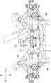
次に、図2乃至図4により、本発明の実施形態による自動車のリヤサブフレーム構造を説明する。図2は、本発明の実施形態による自動車のリヤサブフレーム構造を車体前方の斜め左側から見た斜視図であり、図3は、本発明の実施形態による自動車のリヤサブフレーム構造を車体上方から見た平面図であり、図4は、本発明の実施形態による自動車のリヤサブフレーム構造を車体前方から見た正面図である。 Next, a rear subframe structure of an automobile according to an embodiment of the present invention will be described with reference to FIGS. FIG. 2 is a perspective view of a rear subframe structure of an automobile according to an embodiment of the present invention as seen from an oblique left side in front of the vehicle body, and FIG. 3 shows a rear subframe structure of the automobile according to an embodiment of the present invention from above the vehicle body. FIG. 4 is a front view of a rear subframe structure of an automobile according to an embodiment of the present invention as viewed from the front of the vehicle body.
リヤサブフレーム2は、車幅方向左右両側においてそれぞれ車体前後方向に延びる左右一対のサイドメンバ20、左右一対のサイドメンバ20を互いに連結するように車幅方向に延びる前クロスメンバ22、及び、左右一対のサイドメンバ20の後端部同士を連結するように車幅方向に延びる後クロスメンバ24を備えている。これらのサイドメンバ20、前クロスメンバ22、及び後クロスメンバ24は、金属(例えば鉄系金属あるいはアルミニウム合金等の軽金属)によって閉断面状に形成されている。
The
特に図4に示すように、左右一対のサイドメンバ20は、車体前後方向に延び、且つ、その前端部同士の間隔は、その後端部同士の間隔よりも大きくなるように形成されている。すなわち、左右一対のサイドメンバ20は、前方へ向かうにつれて直線状に車幅方向外側に向かうように形成されている。また、サイドメンバ20は、側面視において、下に凸となるように緩やかに湾曲形成されている。
In particular, as shown in FIG. 4, the pair of left and
前クロスメンバ22は、左右一対のサイドメンバ20の前端部と後端部との間、より具体的にはサイドメンバ20の前後方向中間位置よりも若干前側の位置において、左右のサイドメンバ20同士を連結している。また、前クロスメンバ22は、正面視においてほぼV字形に形成されており、前クロスメンバ22の両端部の高さはサイドメンバ20よりも高くなっている。
この前クロスメンバ22は、その中央部と左右両端部との間において、左右のサイドメンバ20の前端部と後端部との間に連結されている。
The
The
前クロスメンバ22は、リヤサブフレーム2を車体のキックアップ部及びリヤフレームに取り付けた状態において、特に図3及び図4に示すように、車体後部に取り付けられたリヤデファレンシャルギヤ26の下方を通るように配置されている。すなわち、リヤデファレンシャルギヤ26は、車体後部の下面と前クロスメンバ22との間に位置する。
The
より詳細には、図4に示すように、前クロスメンバ22は、最下部(すなわち正面視におけるV字形の底部)が、車幅方向中央(一点鎖線で示す)からリヤデファレンシャルギヤ26のリングギヤ28(破線で示す)がある側にオフセットするように形成されている。より具体的には、前クロスメンバ22の最下部は、リヤデファレンシャルギヤ26のギヤケース30において外径が最も大きい部分、すなわちリングギヤ28を覆う部分の前下方に位置するようになっている。
More specifically, as shown in FIG. 4, the
そして、前クロスメンバ22において、リヤデファレンシャルギヤ26のリングギヤ28がある側の一方の端部と最下部との間は、直線状に形成されている。また、前クロスメンバ22は、リヤデファレンシャルギヤ26のリングギヤ28がない側の他方の端部と最下部との間において、上に凸に屈曲した屈曲部22aを有している。リヤサブフレーム2を車体後部に下方から取り付けた状態において、この屈曲部22aの下方に、排気管32(仮想線で示す)が配設される。
In the
後クロスメンバ24は、その中央部近傍において、左右一対のサイドメンバ20の後端部と連結されている。後クロスメンバ24の両端部は、サイドメンバ20の後端部よりも若干車幅方向外側まで延び、サイドメンバ20の後端部よりも高い位置とされている。そして、前クロスメンバ22の両端部の高さ位置と、後クロスメンバ24の両端部の高さ位置とは、ほぼ等しくなるようにされている。なお、サイドメンバ20、前クロスメンバ22、及び後クロスメンバ24は、例えば溶接により互いに接合されている。
The
次に、図5により、本発明の実施形態による自動車のリヤサブフレーム構造の車体への取り付けについて説明する。図5は、本発明の実施形態による自動車のリヤサブフレーム構造を適用したリヤサスペンション装置1を車体左側から見た側面図である。なお、図5において、リヤサブフレーム2の車体への取付位置を黒星印により示す。
Next, with reference to FIG. 5, attachment of the rear subframe structure of the automobile to the vehicle body according to the embodiment of the present invention will be described. FIG. 5 is a side view of the
ここで、車体は、車室の底面を構成する車室フロア部34と、車室フロア部34の後端から後上方へ後傾して延びるキックアップ部36と、キックアップ部36の上端から後方へ水平に延びるリヤパネル部38とを有する。キックアップ部36の後部は水平方向に屈曲してリヤパネル部38に接続されている。また、リヤパネル部38の下面には、車幅方向左右両側において前後方向に延びる一対のリヤサイドフレーム40(リヤフレーム)が接合されている。
Here, the vehicle body includes a vehicle
リヤサブフレーム2の左右のサイドメンバ20の前端部は、それぞれ、キックアップ部36の前部下面に連結される。また、前クロスメンバ22の両端部は、それぞれ、左右のリヤサイドフレーム40の前端部下面に連結される。特に、図5に示すように、リヤサイドフレーム40への前クロスメンバ22の連結部は、前クロスメンバ22の前側に配置されている。さらに、後クロスメンバ24の両端部は、それぞれ、左右のリヤサイドフレーム40の後部下面に連結される。
The front end portions of the left and
次に、図1及び図5乃至図7により、リヤサブフレーム2へのサスペンションリンクの取付構造を詳細に説明する。図6は、前クロスメンバ22の左端部及び後クロスメンバ24の左端部と、リヤサイドフレーム40との連結位置近傍を車体前方の斜め左側から見た部分拡大斜視図であり、図7は、左側サイドメンバ20へのサスペンションリンクの連結位置近傍を車体上方から見た部分拡大平面図である。また、図5において、上述した5本のサスペンションリンクのリヤサブフレーム2への取付位置を黒丸印により示す。
Next, the suspension link mounting structure to the
リヤサブフレーム2には、車幅方向左右両側において、それぞれ5本ずつのサスペンションリンクが取り付けられる。具体的には、まず、図1、図5及び図6に示すように、左右一対のサイドメンバ20の前端部上面側には、上方に突出する取付部42が設けられており、この取付部42には、前側の前ロアリンク8(トレーリングリンク)の車体側の端部がゴムブッシュを介して取り付けられている。図7に示すように、前ロアリンク8は、取付部42から車体後方に向かって後傾して延び、車輪側の端部が車輪支持部材6に連結される。
Five suspension links are attached to the
次に、図1、図6及び図7に示すように、前クロスメンバ22のサイドメンバ20への連結部上方には、車幅方向外方に突出する取付部44が設けられており、この取付部44には、中央の中ロアリンク10の車体側の端部がゴムブッシュを介して取り付けられている。中ロアリンク10は、取付部44から車体外方に向かって車幅方向に延び、車輪側の端部が車輪支持部材6に連結される。
Next, as shown in FIGS. 1, 6, and 7, a mounting
次に、図6及び図7に示すように、後クロスメンバ24の車幅方向両端部の下面側には、下方に突出する取付部46が設けられており、この取付部46には、後側の後ロアリンク12(トーコントロールリンク)の車体側の端部がゴムブッシュを介して取り付けられている。図1及び図7に示すように、後ロアリンク12は、取付部46から車体外方に向かって車幅方向に延び、車輪側の端部が車輪支持部材6に連結される。
Next, as shown in FIGS. 6 and 7, mounting
次に、図1及び図6に示すように、前クロスメンバ22には、その車幅方向両端から車幅方向外方に突出する取付部48が設けられており、この取付部48には、前側の前アッパリンク14(ラテラルリンク)の車体側の端部がゴムブッシュを介して取り付けられている。すなわち、図5及び図6に示すように、取付部48は、リヤサイドフレーム40への前クロスメンバ22の連結部の後方に配置されている。前アッパリンク14は、取付部48から車体外方に向かって車幅方向に延び、車輪側の端部が車輪支持部材6に連結される。
Next, as shown in FIGS. 1 and 6, the
次に、図1、図5及び図6に示すように、後クロスメンバ24には、その車幅方向両端から車体後方に突出する取付部50が設けられており、この取付部50には、後側の後アッパリンク16(リーディングリンク)の車体側の端部がゴムブッシュを介して取り付けられている。すなわち、図5及び図6に示すように、取付部50は、リヤサイドフレーム40への後クロスメンバ24の連結部の後方に配置されている。図1、図5及び図6に示すように、後アッパリンク16は、取付部50から車体前方に向かって前傾して延び、車輪側の端部が車輪支持部材6に連結される。
Next, as shown in FIGS. 1, 5, and 6, the
次に、図7及び図8により、前ロアリンク8の左右一対のサイドメンバ20への取付部42近傍の構造について、詳細に説明する。図8は、図4におけるVIII−VIII線の矢視図であり、右側サイドメンバ20の内部構造を示す図である。
Next, the structure in the vicinity of the
まず、図7に示すように、サイドメンバ20は、その長手方向に直交する断面の幅が、サイドメンバ20の前後端から前ロアリンク8の取付部42に向かって拡大するように形成されている。すなわち、サイドメンバ20の長手方向に直交する断面積は、取付部42の下方において最大となっている。
First, as shown in FIG. 7, the
上述したように、サイドメンバ20は金属によって閉断面状に形成されている。そして、図8に示すように、サイドメンバ20の内部には、前クロスメンバ22との連結位置の下方において、サイドメンバ20の長手方向に直交する平板状の補強部材52が設けられている。より具体的には、補強部材52は、前クロスメンバ22の車体前方側壁面の下方と、前クロスメンバ22の車体後方側壁面の下方において、それぞれサイドメンバ20の長手方向に直交するように設けられている。これらの補強部材52は、例えば溶接によりサイドメンバ20の内壁に接合されている。
As described above, the
次に、図9乃至図11により、リヤサブフレーム2へのスタビライザの取付構造を説明する。図9は、本発明の実施形態による自動車のリヤサブフレーム構造を車体後方から見た背面図であり、図10は、本発明の実施形態による後クロスメンバ24のスタビ支持台座近傍を車体左側から見た部分拡大側面図であり、図11は、図10におけるXI−XI線の矢視図であり、後クロスメンバ24の内部構造を示す図である。
Next, referring to FIGS. 9 to 11, a structure for attaching the stabilizer to the
まず、図9に示すように、後クロスメンバ24の車幅方向左右両端部の車体後方側に、スタビライザ台座54が設けられている。より詳細には、図10に示すように、スタビライザ台座54は、後クロスメンバ24の車幅方向両端から車体後方に突出している後アッパリンク16の取付部50の下面と、後クロスメンバ24の車体後方側の面とを連結するように設けられている。そして、図9及び図10に示すように、左右一対のスタビライザ台座54の車体方向後側に、スタビライザブラケット56を用いてスタビライザ58が固定される。スタビライザ58は、左右一対のスタビライザ台座54の位置からさらに車幅方向外方に向かって延び、車輪側の両端部が例えばリンク60を介して後ロアリンク12に連結される。
First, as shown in FIG. 9, a
上述したように、後クロスメンバ24は金属によって閉断面状に形成されている。そして、図11に示すように、後クロスメンバ24の内部には、スタビライザ台座54の前方において、後クロスメンバ24の長手方向に直交する平板状の補強部材62が設けられている。さらに、後クロスメンバ24の内部には、後アッパリンク16の取付部50の車体前方において、後クロスメンバ24の長手方向に直交する平板状の補強部材64が設けられている。これらの補強部材62、64は、例えば溶接により後クロスメンバ24の内壁に接合されている。
As described above, the
次に、上述した本発明の実施形態による自動車のリヤサブフレーム構造の効果を説明する。 Next, effects of the rear sub-frame structure of the automobile according to the above-described embodiment of the present invention will be described.
まず、正面視における前クロスメンバ22のV字形の底部が車幅方向中央からリヤデファレンシャルギヤ26のリングギヤ28がある側にオフセットしているので、前クロスメンバ22におけるリヤデファレンシャルギヤ26のリングギヤ28がない側の端部と最下部との間の下方の空間を一層大きく確保することができ、これにより、その空間に排気管32を配設する場合に、前クロスメンバ22におけるリヤデファレンシャルギヤ26のリングギヤ28がない側の端部と最下部との間を、排気管32との干渉を避けつつ、より直線的に形成できる。したがって、前クロスメンバ22の補強をしなくてもNVH性能を向上させることができる。
すなわち、前クロスメンバ22と排気管32との干渉を避けつつ、補強による重量増を抑制しながらNVH性能を向上させることができる。
First, since the V-shaped bottom portion of the
That is, NVH performance can be improved while avoiding interference between the
また、前クロスメンバ22におけるリヤデファレンシャルギヤ26のリングギヤ28がない側の端部と最下部との間の下方の空間を一層大きく確保することができるので、その空間に排気管32を配設する場合に、NVH性能を向上させつつ、前クロスメンバ22と排気管32との干渉を確実に避けることができる。
In addition, since a larger space can be ensured between the end portion of the
また、リヤサブフレーム2が車体のリヤサイドフレーム40に連結される前クロスメンバ22の連結点は、リヤサブフレーム2に前アッパリンク14が取り付けられる取付部48より前方に配置され、車体のリヤサイドフレーム40に連結される後クロスメンバ24の連結点は、リヤサブフレーム2に後アッパリンク16が取り付けられる取付部50より前方に配置されているので、車体のリヤサイドフレーム40とリヤサブフレーム2とを協働させることにより完成車の状態でリヤサブフレーム2に必要な剛性を得る際に、後アッパリンク16の取付部50よりも前方の位置まで車体のリヤサイドフレーム40を補強すればよく、車体のリヤサイドフレーム40に補強を施す前後長さを短くすることができる。従って、車体のリヤサイドフレーム40の質量増加を抑制しつつ、このリヤサイドフレーム40にリヤサブフレーム2を取り付けた状態でリヤサブフレーム2に必要な剛性を得ることができる。
また、上述したように、車体のリヤサイドフレーム40とリヤサブフレーム2とを協働させることにより完成車の状態でリヤサブフレーム2に必要な剛性を得る際に、後アッパリンク16の取付部50よりも前方の位置まで車体のリヤサイドフレーム40を補強すればよいので、この補強による質量増を車両の中央側に集中させることができ、車両の回頭性を向上させることができる。
さらに、リヤサブフレーム2が車体のリヤサイドフレーム40に連結される前後クロスメンバ22、24の連結点と、リヤサブフレーム2に前後アッパリンク14、16が取り付けられる取付部48、50とは、それぞれ前後方向にオフセットして配置されているので、車体に対する前クロスメンバ22及び後クロスメンバ24の連結点を、前後アッパリンク14、16の取付部48、50と干渉することなく、車幅方向で最も車外側に配置された車体の強度部材である左右一対のリヤサイドフレーム40に設けることができる。これにより、車体がリヤサブフレーム2から荷重を受ける車幅方向の長さを大きくすることができ、車体がリヤサブフレーム2から荷重を受けた際のねじれ低減等に有利である。
Further, the connection point of the
Further, as described above, when the
Further, the connecting points of the front and
また、リヤサスペンション装置1の性能向上の観点から後アッパリンク16の前傾角度を大きく取ることにより、後アッパリンク16の車体側の取付部50が車輪から大きく後方に位置する場合でも、車体のリヤサイドフレーム40を補強する際にはこの後アッパリンク16の取付部50よりも前方の位置まで補強すればよく、車体のリヤサイドフレーム40に補強を施す前後長さを短くすることができる。
また、マルチリンク式のリヤサスペンション装置1においては、上下に揺動するドライブシャフトやサスペンションダンパ18が前アッパリンク14と後アッパリンク16との間に配置されるが、車体に対する前クロスメンバ22の連結点が前アッパリンク14の車体側の取付部48より前方に配置されているので、この連結点とドライブシャフトやサスペンションダンパ18との干渉や組み付け作業性の悪化を防止することができる。
Further, from the viewpoint of improving the performance of the
In the multi-link type
また、サイドメンバ20は、その長手方向に直交する断面の幅が、サイドメンバ20の前後端から前ロアリンク8の取付部42に向かって拡大するように形成されているので、前ロアリンク8の取付部42の近傍におけるサイドメンバ20の曲げ剛性やねじり剛性を向上させることができ、これにより、前ロアリンク8から取付部42を介してサイドメンバ20に加えられる力に対するサイドメンバ20の剛性を向上させることができる。
また、追加の補強部材を設ける必要がなく、前クロスメンバ22や後クロスメンバ24とサイドメンバ20との連結部の近傍に取付部42を設ける必要もないので、補強による重量の増大や前ロアリンク8の取付位置の制限を招くことなく、前ロアリンク8から加えられる力に対するサイドメンバ20の剛性を向上させることができる。
Further, the
Further, there is no need to provide an additional reinforcing member, and there is no need to provide the
また、前クロスメンバ22との連結位置の下方において、サイドメンバ20の長手方向に直交する平板状の補強部材52が設けられているので、前ロアリンク8から取付部42を介してサイドメンバ20に加えられる力に対するサイドメンバ20の剛性を向上させることに加えて、前クロスメンバ22からサイドメンバ20に加えられる力に対するサイドメンバ20の剛性を向上させることができ、ドライバの運転操作に対する応答性や剛性感を一層向上させることができる。
Further, since a flat plate-like reinforcing
また、後クロスメンバ24の車体後方側面の上端部から車体後方に片持ち状に突出する後アッパリンク16の取付部50の下面と、後クロスメンバ24の車体後方側面とを連結するように、スタビライザ台座54が設けられているので、このスタビライザ台座54により後アッパリンク16の取付部50の車体上方や下方への屈曲を抑制することができる。したがって、補強による重量の増大を招くことなく、後アッパリンク16から加えられる力による取付部50の屈曲を抑制することができる。
Further, the lower surface of the mounting
また、後クロスメンバ24の内部には、スタビライザ台座54との連結位置の車体前方において、後クロスメンバ24の長手方向に直交する平板状の補強部材62が設けられているので、後アッパリンク16から取付部50及びスタビライザ台座54を介して後クロスメンバ24に加えられる力に対する後クロスメンバ24の剛性を向上させることができ、これにより、後アッパリンク16の取付部50の屈曲を一層確実に抑制することができる。
In addition, a flat reinforcing
また、後クロスメンバ24の内部には、後アッパリンク16の取付部50の車体前方において、後クロスメンバ24の長手方向に直交する平板状の補強部材64が設けられているので、後アッパリンク16から取付部50を介して後クロスメンバ24に加えられる力に対する後クロスメンバ24の剛性を向上させることができ、これにより、後アッパリンク16の取付部50の屈曲を一層確実に抑制することができる。
In addition, a flat reinforcing
また、一対のサイドメンバ20は、後クロスメンバ24への連結位置から車体のキックアップ部36の前部への連結位置に向かって、車幅方向左右両側においてそれぞれ車体前後方向に延びると共に車幅方向外側に広がるように形成されているので、後突時の荷重は、リヤサイドフレーム40を経由してキックアップ部36の後部に直接伝達されると共に、サイドメンバ20を経由してキックアップ部36の前部へ伝達される。すなわち、後突時の荷重の一部がサイドメンバ20に分散されるので、キックアップ部36の後部の屈曲部に加わる荷重を低減でき、これにより、キックアップ部36の後部で座屈が生じることを防止しつつキックアップ部36の傾斜をより立ち上げることができる。したがって、後突時の荷重に対して従来と同等以上の構造強度を確保しつつ、車室後方の車体の前後長を短縮することができる。
The pair of
また、後突時の荷重の一部をサイドメンバ20に分散させることでキックアップ部36の後部の屈曲部に加わる荷重を低減しつつ、車軸を配置するための空間をサイドメンバ20の上方に確保することができる。
In addition, by dispersing a part of the load at the time of the rear collision to the
1 リヤサスペンション装置
2 リヤサブフレーム
4 リヤサスペンション
6 車輪支持部材
8 前ロアリンク(トレーリングリンク)
10 中ロアリンク
12 後ロアリンク(トーコントロールリンク)
14 前アッパリンク(ラテラルリンク)
16 後アッパリンク(リーディングリンク)
18 サスペンションダンパ
20 サイドメンバ
22 前クロスメンバ
22a 屈曲部
24 後クロスメンバ
26 リヤデファレンシャルギヤ
28 リングギヤ
30 ギヤケース
32 排気管
34 車室フロア部
36 キックアップ部
38 リヤパネル部
40 リヤサイドフレーム
42、44、46、48、50 取付部
52 補強部材
54 スタビライザ台座
56 スタビライザブラケット
58 スタビライザ
60 リンク
62、64 補強部材
DESCRIPTION OF
10 Middle
14 Previous upper link (lateral link)
16 Rear upper link (reading link)
DESCRIPTION OF
Claims (3)
車幅方向左右両側においてそれぞれ車体前後方向に延び、その前端部が上記車体のキックアップ部の前部に連結される一対のサイドメンバと、
上記一対のサイドメンバを互いに連結するように車幅方向に延び、その左右両端部が上記サイドメンバよりも高い位置で上記車体のリヤフレームに連結される前クロスメンバと、
上記一対のサイドメンバの後端部においてこれらのサイドメンバを互いに連結するように車幅方向に延び、その左右両端部が上記車体のキックアップ部の後方において上記サイドメンバよりも高い位置で上記車体のリヤフレームに連結される後クロスメンバと、を備え、
上記マルチリンク式のリヤサスペンション装置が備えるサスペンションリンクの内、1組の左右一対のサスペンションリンクの車体側の端部が取り付けられる取付部は、上記一対のサイドメンバの前端部と上記前クロスメンバとの間において、上記一対のサイドメンバの上面に配置され、
上記一対のサイドメンバは、そのサイドメンバの長手方向に直交する断面の幅が、上記サイドメンバの前後端から上記取付部に向かって拡大するように形成されている、
ことを特徴とする自動車のリヤサブフレーム構造。 A rear sub-frame structure of an automobile which is attached to a kick-up portion of a vehicle body and a rear frame and becomes a part of a multi-link type rear suspension device,
A pair of side members that extend in the longitudinal direction of the vehicle body on the left and right sides in the vehicle width direction, and whose front end portions are connected to the front portion of the kick-up portion of the vehicle body;
A front cross member that extends in the vehicle width direction so as to connect the pair of side members to each other and whose left and right ends are connected to the rear frame of the vehicle body at a position higher than the side members;
The vehicle body extends in the vehicle width direction so as to connect the side members to each other at the rear end portions of the pair of side members, and the left and right ends thereof are higher than the side members behind the kick-up portion of the vehicle body. A rear cross member coupled to the rear frame of the
Of the suspension links provided in the multi-link type rear suspension device, the mounting portions to which the vehicle body side ends of the pair of left and right suspension links are attached include the front end portions of the pair of side members, the front cross member, Between the upper surfaces of the pair of side members,
The pair of side members are formed such that the width of the cross section perpendicular to the longitudinal direction of the side members increases from the front and rear ends of the side members toward the mounting portion.
A rear sub-frame structure for an automobile.
Priority Applications (1)
| Application Number | Priority Date | Filing Date | Title |
|---|---|---|---|
| JP2014030775A JP6156649B2 (en) | 2014-02-20 | 2014-02-20 | Rear subframe structure of automobile |
Applications Claiming Priority (1)
| Application Number | Priority Date | Filing Date | Title |
|---|---|---|---|
| JP2014030775A JP6156649B2 (en) | 2014-02-20 | 2014-02-20 | Rear subframe structure of automobile |
Publications (2)
| Publication Number | Publication Date |
|---|---|
| JP2015155254A true JP2015155254A (en) | 2015-08-27 |
| JP6156649B2 JP6156649B2 (en) | 2017-07-05 |
Family
ID=54774874
Family Applications (1)
| Application Number | Title | Priority Date | Filing Date |
|---|---|---|---|
| JP2014030775A Active JP6156649B2 (en) | 2014-02-20 | 2014-02-20 | Rear subframe structure of automobile |
Country Status (1)
| Country | Link |
|---|---|
| JP (1) | JP6156649B2 (en) |
Cited By (1)
| Publication number | Priority date | Publication date | Assignee | Title |
|---|---|---|---|---|
| JP2021133741A (en) * | 2020-02-25 | 2021-09-13 | 日本製鉄株式会社 | Rear subframe |
Citations (7)
| Publication number | Priority date | Publication date | Assignee | Title |
|---|---|---|---|---|
| JPS6168971U (en) * | 1984-10-11 | 1986-05-12 | ||
| JPS6394869U (en) * | 1986-12-10 | 1988-06-18 | ||
| JPH10217735A (en) * | 1997-01-31 | 1998-08-18 | Honda Motor Co Ltd | Suspension for vehicle |
| JP2005262924A (en) * | 2004-03-16 | 2005-09-29 | Toyota Motor Corp | Suspension mounting structure |
| JP2005280668A (en) * | 2004-03-31 | 2005-10-13 | Honda Motor Co Ltd | Sub-frame for vehicle |
| JP2008114652A (en) * | 2006-11-01 | 2008-05-22 | Toyota Motor Corp | Car body rear part structure |
| JP2013103540A (en) * | 2011-11-11 | 2013-05-30 | Mazda Motor Corp | Vehicle rear body structure |
-
2014
- 2014-02-20 JP JP2014030775A patent/JP6156649B2/en active Active
Patent Citations (7)
| Publication number | Priority date | Publication date | Assignee | Title |
|---|---|---|---|---|
| JPS6168971U (en) * | 1984-10-11 | 1986-05-12 | ||
| JPS6394869U (en) * | 1986-12-10 | 1988-06-18 | ||
| JPH10217735A (en) * | 1997-01-31 | 1998-08-18 | Honda Motor Co Ltd | Suspension for vehicle |
| JP2005262924A (en) * | 2004-03-16 | 2005-09-29 | Toyota Motor Corp | Suspension mounting structure |
| JP2005280668A (en) * | 2004-03-31 | 2005-10-13 | Honda Motor Co Ltd | Sub-frame for vehicle |
| JP2008114652A (en) * | 2006-11-01 | 2008-05-22 | Toyota Motor Corp | Car body rear part structure |
| JP2013103540A (en) * | 2011-11-11 | 2013-05-30 | Mazda Motor Corp | Vehicle rear body structure |
Cited By (2)
| Publication number | Priority date | Publication date | Assignee | Title |
|---|---|---|---|---|
| JP2021133741A (en) * | 2020-02-25 | 2021-09-13 | 日本製鉄株式会社 | Rear subframe |
| JP7421091B2 (en) | 2020-02-25 | 2024-01-24 | 日本製鉄株式会社 | rear subframe |
Also Published As
| Publication number | Publication date |
|---|---|
| JP6156649B2 (en) | 2017-07-05 |
Similar Documents
| Publication | Publication Date | Title |
|---|---|---|
| JP6137488B2 (en) | Rear subframe structure of automobile | |
| US9783234B2 (en) | Sub frame structure of vehicle | |
| US8857836B2 (en) | Sub frame structure of automotive vehicle | |
| JP6052512B2 (en) | Rear subframe structure of automobile | |
| CN110949523B (en) | Vehicle body front structure | |
| CN102398631A (en) | Trailing arm mounting structure | |
| JP6074510B2 (en) | Assembly method for vehicle rear suspension mounting structure | |
| JP5954168B2 (en) | Rear body structure | |
| JP6160367B2 (en) | Vehicle suspension system | |
| CN110475681A (en) | Rear overhang rack construction | |
| CN108974125B (en) | Suspension arm support structure | |
| JP6156649B2 (en) | Rear subframe structure of automobile | |
| JP6331589B2 (en) | Trailing arm mounting structure | |
| JP6066102B2 (en) | Rear subframe structure of automobile | |
| JP2010089549A (en) | Stabilizer mounting structure | |
| JP6048682B2 (en) | Front body structure of the vehicle | |
| JP2020131731A (en) | Vehicle rear part structure | |
| JP6137487B2 (en) | Rear subframe structure of automobile | |
| KR100821783B1 (en) | Subframe for a car | |
| JP2006192932A (en) | Rear suspension device of automobile | |
| JP7083035B2 (en) | Subframe structure | |
| JP6204159B2 (en) | Car body rear structure | |
| JP2011020465A (en) | Rear sub-frame structure for vehicle | |
| JP5375181B2 (en) | Rear body structure of the vehicle | |
| KR20220006957A (en) | Sub frame for electiric vehicle |
Legal Events
| Date | Code | Title | Description |
|---|---|---|---|
| A621 | Written request for application examination |
Free format text: JAPANESE INTERMEDIATE CODE: A621 Effective date: 20160225 |
|
| A977 | Report on retrieval |
Free format text: JAPANESE INTERMEDIATE CODE: A971007 Effective date: 20161013 |
|
| A131 | Notification of reasons for refusal |
Free format text: JAPANESE INTERMEDIATE CODE: A131 Effective date: 20161102 |
|
| TRDD | Decision of grant or rejection written | ||
| A01 | Written decision to grant a patent or to grant a registration (utility model) |
Free format text: JAPANESE INTERMEDIATE CODE: A01 Effective date: 20170510 |
|
| A61 | First payment of annual fees (during grant procedure) |
Free format text: JAPANESE INTERMEDIATE CODE: A61 Effective date: 20170523 |
|
| R150 | Certificate of patent or registration of utility model |
Ref document number: 6156649 Country of ref document: JP Free format text: JAPANESE INTERMEDIATE CODE: R150 |