JP2015150737A - injection molding machine - Google Patents
injection molding machine Download PDFInfo
- Publication number
- JP2015150737A JP2015150737A JP2014025085A JP2014025085A JP2015150737A JP 2015150737 A JP2015150737 A JP 2015150737A JP 2014025085 A JP2014025085 A JP 2014025085A JP 2014025085 A JP2014025085 A JP 2014025085A JP 2015150737 A JP2015150737 A JP 2015150737A
- Authority
- JP
- Japan
- Prior art keywords
- screw
- cylinder
- supply port
- injection molding
- molding machine
- Prior art date
- Legal status (The legal status is an assumption and is not a legal conclusion. Google has not performed a legal analysis and makes no representation as to the accuracy of the status listed.)
- Pending
Links
- 238000001746 injection moulding Methods 0.000 title claims abstract description 24
- 239000000463 material Substances 0.000 claims abstract description 56
- 239000011347 resin Substances 0.000 claims abstract description 29
- 229920005989 resin Polymers 0.000 claims abstract description 29
- 206010006514 bruxism Diseases 0.000 claims description 8
- 239000002994 raw material Substances 0.000 abstract 4
- 239000000243 solution Substances 0.000 abstract 1
- 239000008188 pellet Substances 0.000 description 24
- 230000002093 peripheral effect Effects 0.000 description 9
- 238000010298 pulverizing process Methods 0.000 description 8
- 238000002347 injection Methods 0.000 description 5
- 239000007924 injection Substances 0.000 description 5
- 238000000465 moulding Methods 0.000 description 5
- 238000010008 shearing Methods 0.000 description 3
- 238000000034 method Methods 0.000 description 1
Images


Landscapes
- Injection Moulding Of Plastics Or The Like (AREA)
Abstract
Description
本発明は、射出成形機に関し、詳しくは、スクリューによって樹脂材料を可塑化する射出成形機に関する。 The present invention relates to an injection molding machine, and more particularly to an injection molding machine that plasticizes a resin material with a screw.
従来、材料供給口と射出口とを有する筒状のシリンダーと、このシリンダーの内部を回転および進退可能なスクリューとを備えており、材料供給口から供給された樹脂材料(例えば、粒状のペレット)をスクリューの回転によって可塑化し、この可塑化した樹脂材料をスクリューの前進によって射出口から成形金型のキャビィテーに射出可能な射出成形機が既に知られている。ここで、下記特許文献1には、材料供給口からシリンダーの内部に樹脂材料が供給される前に、予め、樹脂材料を細かく砕く粉砕装置を備えた射出成形機が開示されている。これにより、通常サイズの樹脂材料(例えば、長手方向の長さが3mm程度のペレット)を使用しても、スクリューは粉砕装置によって細かく砕かれた後の樹脂材料をせん断することとなる。そのため、このせん断に要するスクリューの長さを短いもので、且つ、スクリューの外周面の溝深さも浅いもので済ますことができる。したがって、スクリューだけでなくシリンダーも小型化できる。 Conventionally, a cylindrical cylinder having a material supply port and an injection port and a screw capable of rotating and advancing and retreating inside the cylinder are provided, and a resin material (for example, granular pellets) supplied from the material supply port There is already known an injection molding machine capable of plasticizing the resin material by rotating the screw and injecting the plasticized resin material from the injection port into the cavity of the molding die by the advance of the screw. Here, Patent Document 1 below discloses an injection molding machine provided with a pulverizing apparatus that finely crushes a resin material before the resin material is supplied into the cylinder from the material supply port. Thereby, even if a resin material having a normal size (for example, a pellet having a length of about 3 mm in the longitudinal direction) is used, the screw shears the resin material after being finely crushed by a pulverizer. Therefore, the screw required for this shearing can be shortened and the groove depth on the outer peripheral surface of the screw can be shallow. Therefore, not only the screw but also the cylinder can be reduced in size.
しかしながら、上述した特許文献1の技術では、シリンダーを小型化できても、粉砕装置を成すカッタおよびその駆動機構(カッタの駆動機構)がスクリューおよびその駆動機構(スクリューの駆動機構)に対して別途に必要となっていた。そのため、シリンダーを小型化できても、必ずしも、射出成形機が小型化されないという問題が発生していた。 However, in the technique disclosed in Patent Document 1 described above, even if the cylinder can be reduced in size, the cutter and its drive mechanism (cutter drive mechanism) constituting the crushing apparatus are separate from the screw and its drive mechanism (screw drive mechanism). Was needed. Therefore, even if the cylinder can be reduced in size, the problem that the injection molding machine is not necessarily reduced in size has occurred.
本発明は、このような課題を解決しようとするもので、その目的は、通常サイズの樹脂材料を使用できる小型の射出成形機を提供することである。 The present invention is intended to solve such problems, and an object of the present invention is to provide a small injection molding machine that can use a resin material having a normal size.
本発明は、上記の目的を達成するためのものであって、以下のように構成されている。
請求項1に記載の発明は、樹脂材料が内部に供給される材料供給口を有している筒状のシリンダーと、このシリンダーの内部を回転可能なスクリューと、を備えており、材料供給口から供給された樹脂材料をスクリューの回転によって可塑化可能な射出成形機であって、スクリューの基端側には、粉砕歯が形成されており、スクリューを回転させているとき、材料供給口から樹脂材料がシリンダーの内部に供給されると、この供給された樹脂材料は材料供給口の縁と粉砕歯との間に挟み込まれて粉砕されることを特徴とする構成である。
この構成によれば、粉砕歯が、従来技術で説明した粉砕装置と同等の役割を果たすこととなる。したがって、従来技術と同様に、通常サイズの樹脂材料を使用しても、スクリューは粉砕歯によって細かく砕かれた後の樹脂材料をせん断することとなる。そのため、このせん断に要するスクリューの長さを短いもので、且つ、スクリューの外周面の溝深さも浅いもので済ますことができる。したがって、スクリューだけでなくシリンダーも小型化できる。このようにシリンダーを小型化できると、従来技術で説明した粉砕装置が不要のため、通常サイズの樹脂材料を使用しても射出成形機を小型化できる。
The present invention is for achieving the above object, and is configured as follows.
The invention described in claim 1 includes a cylindrical cylinder having a material supply port through which a resin material is supplied, and a screw capable of rotating inside the cylinder. An injection molding machine capable of plasticizing the resin material supplied from the screw by rotating the screw, and crushed teeth are formed on the base end side of the screw. When the resin material is supplied into the cylinder, the supplied resin material is sandwiched between the edge of the material supply port and the pulverized teeth and pulverized.
According to this structure, a grinding | pulverization tooth will play the role equivalent to the grinding | pulverization apparatus demonstrated by the prior art. Therefore, as in the prior art, even if a resin material having a normal size is used, the screw shears the resin material after being finely crushed by the grinding teeth. Therefore, the screw required for this shearing can be shortened and the groove depth on the outer peripheral surface of the screw can be shallow. Therefore, not only the screw but also the cylinder can be reduced in size. If the cylinder can be miniaturized in this way, the pulverizing apparatus described in the prior art is unnecessary, and therefore the injection molding machine can be miniaturized even if a resin material of normal size is used.
また、請求項2に記載の発明は、請求項1に記載の射出成形機であって、材料供給口は、シリンダーの軸芯に対してスクリューの回転方向側に横ズレした位置に形成されていることを特徴とする構成である。
この構成によれば、材料供給口がシリンダーの軸芯に対してスクリューの回転方向側に横ズレした位置に形成されていない場合と比較すると、材料供給口の縁と粉砕歯との間に多くの樹脂材料を挟み込んで粉砕できる。したがって、樹脂材料の粉砕の効率を高めることができる。
The invention according to
According to this configuration, compared with the case where the material supply port is not formed at a position shifted laterally in the rotational direction of the screw with respect to the axial center of the cylinder, there are many between the edge of the material supply port and the grinding teeth. The resin material can be sandwiched and pulverized. Therefore, the efficiency of pulverization of the resin material can be increased.
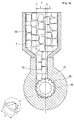
以下、本発明を実施するための形態を、図1〜3を用いて説明する。なお、以下に説明する実施の形態においても、従来技術の説明と同様に、樹脂材料が通常サイズ(例えば、長手方向の長さが3mm程度)のペレット30である形態を説明していく。まず、図1〜2を参照して、本発明の実施例に係る射出成形機1の構成を説明する。 Hereinafter, the form for implementing this invention is demonstrated using FIGS. 1-3. In the embodiment described below, as in the description of the prior art, an embodiment in which the resin material is a pellet 30 having a normal size (for example, a length in the longitudinal direction of about 3 mm) will be described. First, with reference to FIGS. 1-2, the structure of the injection molding machine 1 which concerns on the Example of this invention is demonstrated.
この射出成形機1は、主として、材料供給口12と射出口16とを有する筒状のシリンダー10と、このシリンダー10の内部を回転および進退可能なスクリュー20とから構成されている。以下に、これらシリンダー10とスクリュー20とを個別に説明していく。
The injection molding machine 1 is mainly composed of a
はじめに、シリンダー10から説明していく。図1に示すように、シリンダー10の基端の上側には、樹脂材料である粒状のペレット30を供給可能な材料供給口12が内部と連通するように形成されている。この材料供給口12には、シリンダー10の内部と連通するホッパー14が設けられている。このホッパー14には、この図1からも明らかなように、多くのペレット30が投入されている。
First, the
このホッパー14により、ペレット30を材料供給口12からシリンダー10の内部に供給できる。この材料供給口12は、例えば、その開口の幅長が「6mm」となるように形成されている(図2参照)。なお、この図2からも明らかなように、この材料供給口12は、シリンダー10の軸芯に対してスクリュー20の回転方向側に、例えば、「2mm」横ズレした位置に形成されている。
The
また、図1に戻って、このシリンダー10の先端には、成形金型のキャビィテー(いずれも図示しない)に可塑化したペレット30を射出可能な射出口16が形成されている。このシリンダー10の外周面の適宜箇所には、複数のバンドヒータ(図示しない)が設けられている。これにより、ペレット30を可塑化するとき、この可塑化の度合いを高めることができる。
Returning to FIG. 1, an
なお、この複数のバンドヒータは、シリンダー10の外周面に設けられることなく、シリンダー10に内蔵されていても構わない。その方が、ペレット30の可塑化の度合いをより高めることができる。このように構成されているシリンダー10は、例えば、その外径が「18.2mm」、その内径が「8.2mm」となるように形成されている。
The plurality of band heaters may be incorporated in the
次に、スクリュー20を説明する。このスクリュー20の外周面には、シリンダー10の内部に供給されたペレット30を可塑化する公知の螺旋状の溝22が形成されている。この螺旋状の溝22は、例えば、この溝22の頂点の径が「8mm」となるように形成されている。この溝22の深さは、その螺旋の基端側から先端側に向けて徐々に浅くなるように形成されている。言い換えると、このスクリュー20の軸径は、その螺旋の基端側から先端側に向けて徐々に太くなるように形成されている。
Next, the
このとき、この溝22の深さは、その螺旋の先端側において、例えば、「1mm」となっており、その螺旋の基端側において、例えば、「1.8mm」となるように形成されている。そのため、このスクリュー20の軸径は、その螺旋の先端側において、例えば、「6mm」となっており、その螺旋の基端側において、例えば、「4.4mm」となるように形成されている。
At this time, the depth of the
また、このスクリュー20の外周面のうち、螺旋状の溝22より基端側の外周面には、複数の粉砕歯24が形成されている。この複数の粉砕歯24は、図2の一部拡大図からも明らかなように、その高さが「1mm」となっており、隣り合う粉砕歯24との間隔が「2mm」となるように形成されている。また、この複数の粉砕歯24は、図1の一部拡大図からも明らかなように、スクリュー20の軸方向に対して「10°」の傾斜を成すように形成されている。
Further, among the outer peripheral surface of the
このように構成されているスクリュー20は、駆動機構によって(図示しない)シリンダー10の内部を回転および進退可能に組み付けられている。なお、このスクリュー20の回転方向は、負荷側(成形金型側)から見て反時計回り方向(図3において、矢印方向)となっている。これらシリンダー10とスクリュー20とから射出成形機1は構成されている。
The
続いて、上述したように構成されている射出成形機1の動作を説明する。まず、ホッパー14にペレット30を投入する作業を行う(図1〜2参照)。この投入されたペレット30は、材料供給口12からシリンダー10の内部に供給されていく。次に、スクリュー20を回転させる作業を行う。
Then, operation | movement of the injection molding machine 1 comprised as mentioned above is demonstrated. First, the operation | work which throws the pellet 30 into the
すると、シリンダー10の内部に供給されたペレット30は、材料供給口12の縁と複数の粉砕歯24との間に挟み込まれて粉砕される(図3参照)。これにより、通常サイズであったペレット30は、例えば、「1mm」程度に細かく粉砕される。そして、細かく粉砕されたペレット30は、従来技術と同様に、スクリュー20の回転によって可塑化された後に、このスクリュー20の前進によって射出口16から成形金型のキャビィテーに射出される。
Then, the pellets 30 supplied to the inside of the
本発明の実施例に係る射出成形機1は、上述したように構成されている。この構成によれば、スクリュー20の外周面のうち、螺旋状の溝22より基端側の外周面には、複数の粉砕歯24が螺旋状を成すように形成されている。そのため、スクリュー20を回転させているとき、材料供給口12からペレット30がシリンダー10の内部に供給されると、この供給されたペレット30は材料供給口12の縁と複数の粉砕歯24との間に挟み込まれて粉砕される(図3参照)。なお、この複数の粉砕歯24が螺旋状を成したものが、従来技術で説明した粉砕装置のカッタと同等の役割を果たすこととなる。したがって、従来技術と同様に、通常サイズのペレット30を使用しても、スクリュー20は複数の粉砕歯24によって細かく砕かれた後のペレット30をせん断することとなる。そのため、このせん断に要するスクリュー20の長さを短いもので、且つ、スクリュー20の外周面の溝22深さも浅いもので済ますことができる。したがって、スクリュー20だけでなくシリンダー10も小型化できる。このようにシリンダー10を小型化できると、従来技術で説明した粉砕装置が不要のため、通常サイズのペレット30を使用しても射出成形機1を小型化できる。
The injection molding machine 1 according to the embodiment of the present invention is configured as described above. According to this configuration, a plurality of pulverized
また、この構成によれば、シリンダー10の材料供給口12は、シリンダー10の軸芯に対してスクリュー20の回転方向側に、例えば、「2mm」横ズレした位置に形成されている。そのため、この材料供給口12がシリンダー10の軸芯に対してスクリュー20の回転方向側に横ズレした位置に形成されていない場合と比較すると、材料供給口12の縁と複数の粉砕歯24との間に多くのペレット30を挟み込んで粉砕できる。したがって、ペレット30の粉砕の効率を高めることができる。
Further, according to this configuration, the
上述した内容は、あくまでも本発明の一実施の形態に関するものであって、本発明が上記内容(各種の数値)に限定されることを意味するものではない。
実施例では、スクリュー20の回転方向は、負荷側(成形金型側)から見て反時計回り方向(図3において、矢印方向)となっている形態を説明した。しかし、これに限定されるものでなく、これとは逆に、スクリュー20の回転方向は、負荷側(成形金型側)から見て時計回り方向となっていても構わない。
The contents described above are only related to one embodiment of the present invention, and do not mean that the present invention is limited to the above contents (various numerical values).
In the embodiment, the embodiment has been described in which the rotation direction of the
1 射出成形機
10 シリンダー
12 材料供給口
20 スクリュー
24 粉砕歯
30 ペレット(樹脂材料)
1
Claims (2)
このシリンダーの内部を回転可能なスクリューと、を備えており、
材料供給口から供給された樹脂材料をスクリューの回転によって可塑化可能な射出成形機であって、
スクリューの基端側には、粉砕歯が形成されており、
スクリューを回転させているとき、材料供給口から樹脂材料がシリンダーの内部に供給されると、この供給された樹脂材料は材料供給口の縁と粉砕歯との間に挟み込まれて粉砕されることを特徴とする射出成形機。 A cylindrical cylinder having a material supply port through which resin material is supplied;
A screw capable of rotating inside the cylinder, and
An injection molding machine capable of plasticizing a resin material supplied from a material supply port by rotating a screw,
On the base end side of the screw, crushed teeth are formed,
When the screw is rotating, if the resin material is supplied from the material supply port to the inside of the cylinder, the supplied resin material is sandwiched between the edge of the material supply port and the grinding teeth and pulverized. An injection molding machine characterized by
材料供給口は、シリンダーの軸芯に対してスクリューの回転方向側に横ズレした位置に形成されていることを特徴とする射出成形機。
The injection molding machine according to claim 1,
An injection molding machine, wherein the material supply port is formed at a position laterally shifted in the rotational direction of the screw with respect to the axis of the cylinder.
Priority Applications (1)
| Application Number | Priority Date | Filing Date | Title |
|---|---|---|---|
| JP2014025085A JP2015150737A (en) | 2014-02-13 | 2014-02-13 | injection molding machine |
Applications Claiming Priority (1)
| Application Number | Priority Date | Filing Date | Title |
|---|---|---|---|
| JP2014025085A JP2015150737A (en) | 2014-02-13 | 2014-02-13 | injection molding machine |
Publications (1)
| Publication Number | Publication Date |
|---|---|
| JP2015150737A true JP2015150737A (en) | 2015-08-24 |
Family
ID=53893509
Family Applications (1)
| Application Number | Title | Priority Date | Filing Date |
|---|---|---|---|
| JP2014025085A Pending JP2015150737A (en) | 2014-02-13 | 2014-02-13 | injection molding machine |
Country Status (1)
| Country | Link |
|---|---|
| JP (1) | JP2015150737A (en) |
Cited By (3)
| Publication number | Priority date | Publication date | Assignee | Title |
|---|---|---|---|---|
| CN109399094A (en) * | 2018-10-23 | 2019-03-01 | 杭州奥拓机电技术股份有限公司 | Vertical spin dental lamina crushes conveying device |
| CN110893660A (en) * | 2019-12-25 | 2020-03-20 | 深圳市领域精密制造有限公司 | Novel injection molding storage device of injection molding machine |
| CN112810086A (en) * | 2020-12-23 | 2021-05-18 | 安徽宜万丰电器有限公司 | Injection molding mechanism of injection mold |
Citations (1)
| Publication number | Priority date | Publication date | Assignee | Title |
|---|---|---|---|---|
| JP2006205461A (en) * | 2005-01-26 | 2006-08-10 | Toyo Mach & Metal Co Ltd | Injection molding machine |
-
2014
- 2014-02-13 JP JP2014025085A patent/JP2015150737A/en active Pending
Patent Citations (1)
| Publication number | Priority date | Publication date | Assignee | Title |
|---|---|---|---|---|
| JP2006205461A (en) * | 2005-01-26 | 2006-08-10 | Toyo Mach & Metal Co Ltd | Injection molding machine |
Cited By (3)
| Publication number | Priority date | Publication date | Assignee | Title |
|---|---|---|---|---|
| CN109399094A (en) * | 2018-10-23 | 2019-03-01 | 杭州奥拓机电技术股份有限公司 | Vertical spin dental lamina crushes conveying device |
| CN110893660A (en) * | 2019-12-25 | 2020-03-20 | 深圳市领域精密制造有限公司 | Novel injection molding storage device of injection molding machine |
| CN112810086A (en) * | 2020-12-23 | 2021-05-18 | 安徽宜万丰电器有限公司 | Injection molding mechanism of injection mold |
Similar Documents
| Publication | Publication Date | Title |
|---|---|---|
| JP2015150737A (en) | injection molding machine | |
| CN204294317U (en) | A kind of medicinal material pulverizer | |
| CN110394121A (en) | High Efficiency Ring Die Granulator | |
| CN104998717A (en) | Millstone of waste rubber pulverizer | |
| CN104289133A (en) | Novel horizontal mixer | |
| JP5118596B2 (en) | Pellet forming equipment | |
| CN107736143A (en) | A kind of high production rate straw millstone | |
| KR100584918B1 (en) | Plastic Waste Shredders | |
| US8714468B2 (en) | Plastic scrap crushing apparatus | |
| CN102371652B (en) | Molding material feed screw used in molding material supply device of injection molding machine | |
| US3151645A (en) | Breaker and shredding cylinder for ear corn | |
| CN204544355U (en) | A kind of pulverizer | |
| CN101992538B (en) | bidirectional single-screw extruder | |
| JP7162914B2 (en) | Crusher | |
| CN203764328U (en) | Reversible hammer-type counterattack composite sand making machine | |
| CN203417727U (en) | Bidirectional feeding type feed grinder | |
| CN203935883U (en) | A kind of new-type cutter pulverizer | |
| JP5969422B2 (en) | Hardened build-up structure of roll | |
| CN209794300U (en) | smashing knife | |
| CN205217009U (en) | Rice bran rubbing crusher | |
| JP2005334712A (en) | Granulator | |
| CN204891967U (en) | Old and useless rubber rubbing crusher's mill | |
| CN206510403U (en) | A single screw extruder | |
| CN211532736U (en) | An environmentally friendly extrusion structure for cattle feed pelletizer | |
| CN104444150A (en) | Double-driven conveying mechanism |
Legal Events
| Date | Code | Title | Description |
|---|---|---|---|
| A621 | Written request for application examination |
Free format text: JAPANESE INTERMEDIATE CODE: A621 Effective date: 20160830 |
|
| A977 | Report on retrieval |
Free format text: JAPANESE INTERMEDIATE CODE: A971007 Effective date: 20170518 |
|
| A131 | Notification of reasons for refusal |
Free format text: JAPANESE INTERMEDIATE CODE: A131 Effective date: 20170704 |
|
| A02 | Decision of refusal |
Free format text: JAPANESE INTERMEDIATE CODE: A02 Effective date: 20181204 |