JP2015139355A - Wire material coating peeling device - Google Patents
Wire material coating peeling device Download PDFInfo
- Publication number
- JP2015139355A JP2015139355A JP2014011751A JP2014011751A JP2015139355A JP 2015139355 A JP2015139355 A JP 2015139355A JP 2014011751 A JP2014011751 A JP 2014011751A JP 2014011751 A JP2014011751 A JP 2014011751A JP 2015139355 A JP2015139355 A JP 2015139355A
- Authority
- JP
- Japan
- Prior art keywords
- support shaft
- iron core
- wire
- peeling
- movable
- Prior art date
- Legal status (The legal status is an assumption and is not a legal conclusion. Google has not performed a legal analysis and makes no representation as to the accuracy of the status listed.)
- Pending
Links
Images


Abstract
Description
本発明は、エナメル線等の線材に施される被膜を剥離する線材被膜剥離装置に関する。 The present invention relates to a wire film peeling apparatus for peeling a film applied to a wire such as an enameled wire.
従来の線材被膜剥離装置として、特許文献1に記載されるものがあった。これによれば、後端口より先端口へ導かれるように中心部に線材の通るガイド孔を有し回転及び軸方向に摺動可能な回転管軸と、回転管軸を回転及び摺動可能に保持する保持台と、回転管軸の先端にガイド孔先端口の周りに配置され、かつ、回転による遠心力で互いに寄り合うように中間支持部を支点に揺動自在に支持された複数のカッタと、回転管軸に間欠的に回転を伝達するクラッチ付き駆動装置と、回転伝達中の回転管軸を前後方へ一定のストロークスライド移動させる押動機構と、回転管軸の後方スライド移動時にガイド孔先端口の前方位置において線材の一部をつかんで線材の移動を阻止する開閉自在なストップ機構と、を備えていた。 There existed what was described in patent document 1 as a conventional wire film peeling apparatus. According to this, a rotating tube shaft having a guide hole through which a wire passes in the center so as to be guided from the rear end port to the front end port, and capable of rotating and sliding in the axial direction, and the rotating tube shaft can be rotated and slid. And a plurality of cutters that are disposed around the tip end of the guide hole at the tip of the rotary tube shaft, and are supported in a swingable manner with an intermediate support portion as a fulcrum so as to face each other by centrifugal force due to rotation A clutch-equipped drive device that intermittently transmits rotation to the rotating tube shaft, a push mechanism that slides the rotating tube shaft that is transmitting the rotation forward and backward, and a guide when the rotating tube shaft slides backward And a freely openable and closable stop mechanism that grips a part of the wire at a position in front of the hole tip and prevents the wire from moving.
また、カッタは、中間支持部を支軸で枢支され、かつ、ばねにより開方向に付勢されたカッタレバーの先端に配設されていた。 In addition, the cutter is disposed at the tip of a cutter lever that is pivotally supported by a support shaft on an intermediate support portion and biased in the opening direction by a spring.
上記構成の線材被膜剥離装置は、駆動装置の駆動により回転管軸が回転し、カッタレバーの先端に配設されたカッタがばねの付勢力に抗して、互いに寄り合うように移動して、一定長ずつ送り出される線材の被膜を剥離することとされていた。 In the wire film peeling apparatus having the above configuration, the rotating tube shaft rotates by driving of the driving device, and the cutter arranged at the tip of the cutter lever moves against each other against the biasing force of the spring, It was supposed that the film of the wire rod sent out by fixed length was peeled off.
上記の線材被膜剥離装置では、カッタレバーの閉方向への移動は、カッタレバーの後端部と当接する調整ねじにより、線材に対するカッタの食い込みは、一定となるように規制されているが、カッタの駆動装置の回転軸からの距離、回転軸の回転の速さ等の回転による遠心力とばねの付勢力とを考慮しなければならないので、カッタを線材に押圧する力の制御が困難であり、被膜の内側部分の芯材を傷つけるおそれがあった。 In the above-described wire film peeling apparatus, the movement of the cutter lever in the closing direction is regulated so that the cutter bite into the wire is constant by the adjusting screw that contacts the rear end of the cutter lever. It is difficult to control the force that presses the cutter against the wire because the centrifugal force and the biasing force of the spring due to the rotation, such as the distance from the rotation shaft of the drive device and the rotation speed of the rotation shaft, must be considered. There was a risk of damaging the core material inside the coating.
本発明は、上述の課題を解決するものであり、カッタ(剥離刃)を線材に押圧する力の制御を可能とし、被膜の内側部分の芯材を傷つけることを抑制する線材被膜剥離装置を提供することを目的とする。 The present invention solves the above-described problems, and provides a wire coating film peeling apparatus that enables control of the force pressing a cutter (peeling blade) against a wire material and suppresses damage to the core material in the inner part of the coating film. The purpose is to do.
請求項1記載の発明では、芯材と芯材の外側を覆う被膜とを有する線材の被膜を剥離する線材被膜剥離装置であって、本体部と、本体部に配設される駆動装置と、駆動装置によって回転する支持軸と、支持軸に軸支される複数の可動片と、可動片に取り付けられる剥離刃と、を備え、支持軸の外側に、ソレノイドが配置され、ソレノイドは、コイルと、固定鉄心と、コイルの励磁により固定鉄心に接近する可動鉄心を有し、固定鉄心は、可動鉄心より駆動装置に近い側で本体部に固定され、可動鉄心は、固定鉄心側に位置する基部と、基部から固定鉄心から離れる側に向かって広がる円錐台形状に形成される摺接部と、を有して、支持軸の外側に嵌められるとともに、支持軸に対して支持軸の軸線方向に沿って摺動可能に形成され、可動片は、支持軸の軸線に沿うとともに支持軸の軸線方向からみて支持軸の軸線の周りに配置され、支持軸の軸線方向における中間部分で軸支され、可動片の軸心を挟んで、可動片の固定鉄心から離れる側の端部には剥離刃が配設され、可動片の固定鉄心側の端部には、摺接部の外周面と摺接可能な当接部が設けられ、駆動装置によって支持軸が回転すると、支持軸の回転の遠心力により、可動片が回動して各剥離刃が支持軸の軸線から離れるように移動し、コイルが励磁されることにより、可動鉄心が固定鉄心に接近するときに、摺接部と、当接部と、が摺接して可動片が回動することにより、各剥離刃が支持軸の軸線側に移動する。 The invention according to claim 1 is a wire film peeling device for peeling a coating of a wire having a core and a coating covering the outside of the core, the main body, and a driving device disposed in the main body, A support shaft that is rotated by the drive device; a plurality of movable pieces that are pivotally supported by the support shaft; and a peeling blade that is attached to the movable piece. A solenoid is disposed outside the support shaft. The fixed iron core has a movable iron core that approaches the fixed iron core by excitation of the coil. The fixed iron core is fixed to the main body on the side closer to the drive device than the movable iron core, and the movable iron core is located on the fixed iron core side. And a sliding contact portion formed in a truncated cone shape that extends from the base toward the side away from the fixed iron core, and is fitted on the outside of the support shaft, and in the axial direction of the support shaft with respect to the support shaft The movable piece is slidable along Along the axis of the support shaft and around the axis of the support shaft as seen from the axial direction of the support shaft, supported by the middle part of the support shaft in the axial direction, and fixed to the movable piece with the axis of the movable piece in between A peeling blade is provided at the end on the side away from the iron core, and an abutting portion that is slidable on the outer peripheral surface of the slidable contact portion is provided on the end of the movable piece on the fixed core side, and is supported by the driving device. When the shaft rotates, the movable piece rotates due to the centrifugal force of the rotation of the support shaft, and each peeling blade moves away from the axis of the support shaft, and the coil is excited, so that the movable core becomes a fixed core. When approaching, the slidable contact portion and the abutting portion are slidably contacted and the movable piece is rotated, whereby each peeling blade moves to the axis side of the support shaft.
これによれば、可動鉄心の摺接部の支持軸の軸線に対する角度、当接部の位置、形状を調整することで、可動鉄心の移動量を調整することが可能となり、それにともない可動片の移動量も調整することが可能となるため、剥離刃を線材に押圧する力の制御を可能とし、被膜の内側部分の芯材を傷つけることを抑制することができる。 According to this, it is possible to adjust the amount of movement of the movable core by adjusting the angle of the sliding contact portion of the movable core with respect to the axis of the support shaft, the position and shape of the contact portion, and accordingly the movable piece Since the amount of movement can also be adjusted, it is possible to control the force for pressing the peeling blade against the wire, and it is possible to suppress damage to the core material in the inner part of the coating.
また、ソレノイドを、比例ソレノイドとすれば、上記効果に加えて、電流の調整により可動鉄心の移動量を調整することが可能となり、それにともない可動片の移動量も調整することが可能となるため、剥離刃を線材に押圧する力の制御の精度を高めることができる。 If the solenoid is a proportional solenoid, in addition to the above effects, it is possible to adjust the amount of movement of the movable core by adjusting the current, and accordingly the amount of movement of the movable piece can also be adjusted. The accuracy of controlling the force for pressing the peeling blade against the wire can be increased.
また、剥離刃を、平板状に形成し、線材の被膜を剥離するときに、支持軸の軸線に直交する面に対して傾斜するように配置することとすれば、線材の被膜に剥離刃の角部が当りやすくなるので、被膜を剥離しやすくすることができる。 In addition, when the peeling blade is formed in a flat plate shape and is disposed so as to be inclined with respect to a plane perpendicular to the axis of the support shaft when peeling the coating of the wire, the peeling blade is formed on the coating of the wire. Since the corners are easy to hit, the coating can be easily peeled off.
また、剥離刃を、線材の被膜を剥離するときに、線材をガイドするガイド部を有することとすれば、線材の移動を規制して、被膜の剥離作業を安定させることができる。 Further, if the peeling blade has a guide portion for guiding the wire when peeling the coating of the wire, the movement of the wire can be restricted and the peeling operation of the coating can be stabilized.
また、可動片に取り付けられた各剥離刃が支持軸の軸線から離れるように付勢する付勢部材を、可動片に配設すれば、駆動装置を駆動させて支持軸を回転させなくとも、可動片を支持軸の軸線から離れた位置に配置させることができる。 Further, if a biasing member that biases each peeling blade attached to the movable piece away from the axis of the support shaft is disposed on the movable piece, the driving device is not driven to rotate the support shaft. The movable piece can be arranged at a position away from the axis of the support shaft.
本発明の線材被膜剥離装置の第一の実施形態を図面に基づいて説明する。以下の説明では、各図面の矢印の、Fを前、Bを後ろ、Rを右、Lを左、Uを上、Dを下、とする。 1st embodiment of the wire film peeling apparatus of this invention is described based on drawing. In the following description, F is the front, B is the back, R is the right, L is the left, U is the top, and D is the bottom of the arrows in each drawing.
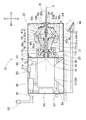
線材被膜剥離装置10は、図1〜3に示すように、概略的には、本体部20と、本体部20に配設される駆動装置30と、駆動装置30によって回転する支持軸40と、支持軸40に軸支される複数の可動片50と、可動片50に取り付けられる剥離刃60と、を備えて、図10、11等に示す、芯材Mと芯材Mの外側を覆う被膜Fとを有する線材Wの被膜Fを剥離するものである。
As shown in FIGS. 1 to 3, the wire
本体部20は、図1〜4、6に示すように、金属製で矩形箱状に形成され、前後方向における中間部分に矩形平板状の仕切板21が配設され、前側に位置して線材Wの被膜Fの剥離作業を行なう作業室22と、後側に位置して駆動装置30が配置される駆動室26と、に区画されている。なお、図1においては、本体部20の壁面の一部を省略している。
1-4 and 6, the
仕切板21の中央部には、前後方向に貫通して、後述する電動モータ31の回転軸32を挿通可能とする挿通孔21aが形成されている。
An
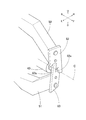
仕切板21の上端部には、蝶番23が配設され、作業室22を構成する、底壁以外の上壁、左右壁、前壁部分が左右方向を軸として開閉可能とされている。底壁の上側には、剥離した被膜Fを回収する引き出し24が、前後方向に沿って移動可能に配置されている。本体部20の作業室22を構成する前壁には、挿通孔20aが設けられ、挿通孔20aには線材Wをガイドするガイド部材25が嵌められている。
A
駆動装置30は、本実施形態では、電動モータ31が用いられ、図1〜3に示すように、本体部20の駆動室26内に配設され、回転軸32を仕切板21の挿通孔21aに挿通させて作業室22に進入させている。電動モータ31は、ハウジング33の仕切板21側の面を仕切板21に密接させて、剥離した被膜Fが駆動室26側に入り込まないように配置されている。
In this embodiment, the
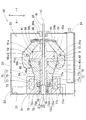
支持軸40は、図1〜4、6、8に示すように、金属製で前後方向に沿って貫通する挿通孔40aを有して円筒状に形成されている。支持軸40は、前後方向における中央より前側に、図2、3の状態において、前後方向からみて、径方向外側に突出する一対の取付部41、42が配設されている。本実施形態では、図1〜4の状態において、上下方向にそれぞれ突出するように形成されている。
As shown in FIGS. 1 to 4, 6, and 8, the
取付部41、42は、図1〜4に示すように、矩形平板状に形成され左右方向に間隔を設けて互いに平行となるように配置された一対の軸支板41a、42aをそれぞれ有して略コの字状に形成されている。取付部41は軸支板41a間に可動片50、取付部42は軸支板42a間に可動片51を、配置可能とされている。軸支板41a、42aには、図2、3の状態において、左右方向に沿って軸支孔41b、42bがそれぞれ形成され、可動片50、51をそれぞれ軸支可能とされている。
As shown in FIGS. 1 to 4, the
各取付部41、42の後側の面は支持軸40の軸線Cに対して直交するように形成され、後述する可動鉄心77の前側の面を受け止める受け止め面41c、42cとして形成されている。
The rear surfaces of the
支持軸40の側の後端部には、止め輪43が装着され、後述するばね79の側の後端部を受け止め可能とされている。
A
支持軸40は、挿通孔40aの後端部に電動モータ31の回転軸32が嵌められ、電動モータ31の駆動力によって回転可能に形成されている。
The
可動片50、51は、図1〜8に示すように、金属製で、前後方向からみて支持軸40の軸線C方向に沿うとともに、左右方向からみて略くの字状に屈曲して形成されている。可動片50、51の前後方向における中央左よりの位置には、左右方向に沿って貫通する軸支孔50a、51aが形成されている。軸支板41aの軸支孔41bと可動片50の軸支孔50a、軸支板42aの軸支孔42bと、可動片51の軸支孔51a、が連通するように配置され、それぞれ軸52が挿通されることによって、可動片50は取付部41に、可動片51は取付部42に、左右方向を軸としてそれぞれ軸支されている。
As shown in FIGS. 1 to 8, the
可動片50、51は、可動片50、51の軸心Sを挟んで、前側(可動片の固定鉄心から離れる側)の端部には剥離刃60、61を取り付け可能な取付面50b、51bがそれぞれ形成され、後側(可動片の固定鉄心側)の端部には、に向かって屈曲して摺接部77bの外周面と摺接可能な当接部50c、51cがそれぞれ設けられている。
The
取付面50bは、図1、3、5、7に示すように、平面視において、支持軸40の軸線Cに直交する面に対して左側が右斜め後方に傾斜するとともに、側面視において、支持軸40の軸線Cに直交する面に対して、上側が斜め後方に傾斜して配置されている。
As shown in FIGS. 1, 3, 5, and 7, the
取付面51bは、図1、3、5、7に示すように、平面視において、支持軸40の軸線Cに直交する面に対して右側が左斜め後方に傾斜するとともに、側面視において、支持軸40の軸線Cに直交する面に対して下側が斜め後方に傾斜して配置されている。
As shown in FIGS. 1, 3, 5, and 7, the
可動片50、51は、偏心した位置で取付部41、42にそれぞれ軸支され、つまり、可動片50、51の軸心Sより剥離刃60、61が配設される前側部分が、可動片50、51の軸心Sより後ろ側より重量が重くなるように形成されている。そして、電動モータ31による支持軸40の回転の遠心力により、可動片50、51の剥離刃60、61が配設される前側が支持軸40の軸線Cから離れるように構成されている。
The
可動片50、51は、可動片50、51の軸心Sを挟んで、前側(可動片の固定鉄心から離れる側)の端部には剥離刃60、61が配設されている。
The
剥離刃60、61は、図1〜9に示すように、矩形平板状に形成され、支持軸40の軸線Cに直交する面に対して、斜め方側に傾斜するとともに、斜め方に傾斜して配置されている。図2、3の状態における、側面視において、80度〜85度傾斜して配置され、平面視において、1度〜20度傾斜して配置されていることが望ましい。
As shown in FIGS. 1 to 9, the
支持軸40の外側には、図1〜4、6、8に示すように、比例ソレノイド70が配置されている。比例ソレノイド70は、固定鉄心71と、コイル76と、コイル76の励磁により固定鉄心71に接近する可動鉄心77を有している。
As shown in FIGS. 1 to 4, 6, and 8, a
固定鉄心71は、可動鉄心77より右側(駆動装置に近い側)の端部で本体部20の仕切板21に固定されている。固定鉄心71は、電動モータ31の回転軸32及び支持軸40を挿通可能に形成されている。
The fixed
固定鉄心71は、内筒部72と、外筒部73と、連結部75と、を有して、二重円筒状に形成されている。
The fixed
内筒部72は、前後方向に貫通する挿通孔72aを有する円筒状に形成され、元部72bと、テーパ部72cと、を有している。テーパ部72cは、外径が前側に行くに従って狭小に形成されている。可動片50、51の当接部50c、51cが、テーパ部72cの外周面を摺接可能に形成されている。
The
内筒部72の挿通孔72aは、後側に位置する小内径部72dと、テーパ部72cに対応する部分で小内径部72dより大径に形成された大内径部72eと、を有している。大内径部72eは、後述する可動鉄心77の小径部77cが摺動可能に形成されている。
The
外筒部73は、円筒状に形成されている。外筒部73の前端縁部から支持軸40の軸線Cに向かって延びる円環状のつば部74が配設されている。元部72bの外径と、つば部74の内周径とは、略同一に形成されている。
The
連結部75は、円環板状に形成され、内筒部72の後側の端部と、外筒部73の後側の端部と、を連結している。
The connecting
固定鉄心71の、内筒部72と、外筒部73と、つば部74と、連結部75で囲まれる部分にコイル76が配置されている。
A
固定鉄心71の後側の面は、支持軸40の軸線Cに直交するように形成され、固定鉄心71は仕切板21に固定されている。
The rear surface of the fixed
可動鉄心77は、後側(固定鉄心側)に位置する円柱状の基部77aと、基部77aから前側(固定鉄心から離れる側)に向かって広がる円錐台形状に形成される摺接部77bと、を有している。
The
基部77aは、小径部77cと、大径部77dと、を有し、小径部77cにおいて、固定鉄心71の内筒部72の大内径部72e内を摺動可能とされている。
The
可動鉄心77は、支持軸40の軸線C方向において貫通する貫通孔77eが設けられ、貫通孔77eの前後方向(支持軸の軸線方向)における両端部に軸受部材78が配置され、支持軸40の外側に嵌められるとともに、支持軸40に対して前後方向に沿って(支持軸の軸線方向に沿って)摺動可能に形成されている。
The
可動鉄心77の後端面は、支持軸40の軸線Cに直交するように形成され、ばね79を受け止め可能とされている。支持軸40の後端部側に装着された止め輪43と、可動鉄心77の後端面との間に、ばね79が配置され、可動鉄心77を前側に付勢している。
The rear end surface of the
駆動装置30及び比例ソレノイド70の電気回路を、図9に基づいて説明する。
The electric circuit of the
駆動装置30としての電動モータ31は、モータコントローラ80、ブレーカー81を介して電源83に接続され、比例ソレノイド70は、ソレノイド電源84、ブレーカー81を介して電源83に接続されている。
The
また、電動モータ31は、モータコントローラ80を介してスピード調整ボリューム85に接続され、スピード調整ボリューム85の接点の移動による電流値の変化により、電動モータ31の回転軸32の回転数を適宜変化可能に構成されている。
The
また、電動モータ31は、モータコントローラ80を介してモータ起動スイッチ86に接続され、電動モータ31の運転、運転停止を切り替え可能とされている。
In addition, the
比例ソレノイド70は、ソレノイド電源84を介して押圧調整ボリューム87に接続され、押圧調整ボリューム87の接点の移動による電流値の変化により、可動鉄心77の移動量を適宜調整可能とされている。また、比例ソレノイド70は、足踏スイッチ88と接続され、足踏スイッチ88のオン、オフの切り替えにより、可動鉄心77の吸着、離脱を切り替え可能とされている。
The
上記構成の線材被膜剥離装置10の使用態様及び作用機能を説明する。
The usage mode and function of the wire
モータ起動スイッチ86をオンにすることで、電動モータ31の駆動により、回転軸32が回転すると、連結している支持軸40が回転する。支持軸40が回転すると、図2、8(a)に示すように、可動片50、51が遠心力により、支持軸40の軸線Cから離れるように移動する。可動片50、51は、偏心して軸支されているので、剥離刃60、61の配設されている前側が支持軸40の軸線Cから離れるように移動する。また、当接部50c、51c側は支持軸40の軸線Cに近づくように移動する。そして、摺接部77bの外周面と、当接部50c、51cとが、当接する。
By turning on the
手で線材Wを、支持軸40の軸線Cに沿うように、ガイド部材35、支持軸40の挿通孔40aに挿通させる。足踏スイッチ88で比例ソレノイド70のコイル76を励磁させ、可動鉄心77を固定鉄心71側に吸引させる。可動鉄心77が固定鉄心71に接近するときに、図3、8(b)に示すように、摺接部77bの外周面と、当接部50c、51cと、が摺接して可動片50、51が回動する。
The wire W is manually inserted through the guide member 35 and the
摺接部77bは、前側に向かって広がる円錐台形状であるので、可動鉄心77が前側に移動すると、当接部50c、51cは、支持軸40の軸線Cから離れるように移動する。それにともない、可動片50、51の剥離刃60、61が配設された前側が支持軸40の軸線Cに近づいて行く。つまり、挿入された線材Wに近づいていく。
Since the sliding
剥離刃60、61は、図2に示す線材Wの被膜Fを剥離する状態において、図10(a)、(b)に示すような側面視において、支持軸40の軸線Cに対し80度〜85度傾斜するように配置されている。これにより、剥離刃60、61が線材Wに押圧する状態で、剥離刃60、61の角部が線材Wに当たるようにすることで、被膜Fの剥離性を良くすることを可能としている。
The
また、剥離刃60、61は、図2に示す線材Wの被膜Fを剥離する状態において、図11に示すような平面視において、支持軸40の軸線Cに対し1度〜20度傾斜するように配置されている。剥離刃60、61が線材Wに押圧する状態で回転することで、矢印の方向に進もうとするが、剥離刃60、61が可動片50、51に固定されているので、相対的に線材Wを後方向に引き込もうとする。これにより、線材Wを手で前側に引き出す動きと相乗して線材Wの被膜Fを効率よく剥離することを可能とする。
Further, the
上記構成の線材被膜剥離装置10では、芯材Nと芯材Nの外側を覆う被膜Fとを有する線材Wの被膜Fを剥離する線材被膜剥離装置であって、本体部20と、本体部20に配設される電動モータ31と、電動モータ31によって回転する支持軸40と、支持軸40に軸支される複数の可動片50、51と、可動片50、51に取り付けられる剥離刃60、61と、を備え、支持軸40の外側に、比例ソレノイド70が配置され、比例ソレノイド70は、コイル76と、固定鉄心71と、コイル76の励磁により固定鉄心71に接近する可動鉄心77を有し、固定鉄心71は、可動鉄心77より電動モータ31に近い側で本体部20に固定され、可動鉄心77は、固定鉄心71側に位置する基部77aと、基部77aから固定鉄心71から離れる側に向かって広がる円錐台形状に形成される摺接部77bと、を有して、支持軸40の外側に嵌められるとともに、支持軸40に対して支持軸40の軸線C方向に沿って摺動可能に形成され、可動片50、51は、支持軸40の軸線Cに沿うとともに支持軸40の軸線C方向からみて支持軸40の軸線Cの周りに配置され、支持軸40の軸線C方向における中間部分で軸支され、可動片50、51の軸心Sを挟んで、可動片50、51の固定鉄心71から離れる側の端部には剥離刃60、61が配設され、可動片50、51の固定鉄心71側の端部には、摺接部77bの外周面と摺接可能な当接部50c、51cが設けられ、電動モータ31によって支持軸40が回転すると、支持軸40の回転の遠心力により、可動片50、51が回動して各剥離刃60、61が支持軸40の軸線Cから離れるように移動し、コイル76が励磁されることにより、可動鉄心77が固定鉄心71に接近するときに、摺接部77bと、当接部50c、51cとが摺接して、可動片50、51が回動することにより、各剥離刃60、61が支持軸40の軸線C側に移動する。
The wire
これによれば、可動鉄心77の摺接部77bの支持軸40の軸線Cに対する角度、当接部50c、51cの位置、形状を調整することで、可動鉄心77の移動量を調整することが可能となり、それにともない可動片50、51の移動量も調整することが可能となるため、剥離刃60、61を線材Wに押圧する力の制御を可能とし、被膜Fの内側部分の芯材Mを傷つけることを抑制することができる。
According to this, the amount of movement of the
また、ソレノイドを、比例ソレノイド70としているので、上記効果に加えて、電流の調整により可動鉄心77の移動量を調整することが可能となり、それにともない可動片50、51の移動量も調整することが可能となるため、剥離刃60、61を線材Wに押圧する力の制御の精度を高めることができる。
Further, since the solenoid is a
また、剥離刃60、61を、平板状に形成し、線材Wの被膜Fを剥離するときに、支持軸40の軸線Cに直交する面に対して傾斜するように配置することとしているので、線材Wの被膜Fに剥離刃60、61の角部が当りやすくなるので、被膜Fを剥離しやすくすることができる。
In addition, when the
本発明の線材被膜剥離装置10は、上記構成に限定されるものではない。即ち、本発明の要旨を逸脱しない限り各種の設計変更等が可能である。
The wire
本発明の第二の実施形態を説明する。以下の説明において、第一の実施形態と同じ構成については、同一符号を付し全部又は一部の説明を省略する。 A second embodiment of the present invention will be described. In the following description, the same components as those of the first embodiment are denoted by the same reference numerals, and the description of all or a part thereof is omitted.
線材被膜剥離装置10Aは、可動片50、51に、可動片50、51の後端部に、前側(各剥離刃が取り付けられた側)が支持軸40の軸線Cから離れるように付勢する付勢部材53としてのリングばね54を、配設している。
The wire coating
詳説すれば、可動片50、51の軸支孔50a、51bの後側に、右方向に貫通する取付孔50d、51dが設けられ、リングばね54を取付孔50d、51d間に架け渡すように配置して、図12の状態において、可動片50、51の前側が、支持軸40の軸線Cから離れるように付勢されている。なお、図15では、軸支孔41b、42b、軸支孔50a、51b、軸52は、省略している。
More specifically, mounting
これにより、電動モータ31を駆動させて支持軸40を回転させなくとも、可動片50、51を支持軸40の軸線Cから離れた位置に配置させることができる。
Accordingly, the
また、図13に示す線材Wの被膜Fを剥離する状態において、図14、15に示すように、上側の剥離刃62には、左側の端部から下方に延びるガイド部62aが、下側の剥離刃63には、右側の端部から上方に延びるガイド部63aが、配設されている。
In the state where the coating F of the wire W shown in FIG. 13 is peeled off, as shown in FIGS. 14 and 15, the
このような構成とすれば、線材Wの移動を規制して、被膜Fの剥離作業を安定させることができる。 If it is set as such a structure, the movement of the wire W can be controlled and the peeling operation | work of the film F can be stabilized.
また、ソレノイドは、比例ソレノイド70を用いているが、オンオフタイプのソレノイドを用いることができる。
Further, although the
また、ガイド部62aを、上側の剥離刃62の左右の端部から下方に延びる構成としたり、ガイド部63aを下側の剥離刃63の左右の端部から上方に延びるが構成としたりすることもできる。
Further, the
10 線材被膜剥離装置
10A 線材被膜剥離装置
20 本体部
30 駆動装置
31 電動モータ
32 回転軸
40 支持軸
40a 挿通孔
41 取付部
42 取付部
50 可動片
51 可動片
53 付勢部材
54 リングばね
60 剥離刃
61 剥離刃
62 剥離刃
62a ガイド部
63 剥離刃
63a ガイド部
70 比例ソレノイド
71 固定鉄心
76 コイル
77 可動鉄心
77a 基部
77b 摺接部
C 軸線
S 軸心
F 被膜
M 芯材
W 線材
DESCRIPTION OF
Claims (5)
本体部と、前記本体部に配設される駆動装置と、前記駆動装置によって回転する支持軸と、前記支持軸に軸支される複数の可動片と、前記可動片に取り付けられる剥離刃と、を備え、
前記支持軸の外側に、ソレノイドが配置され、
前記ソレノイドは、コイルと、固定鉄心と、前記コイルの励磁により前記固定鉄心に接近する可動鉄心を有し、
前記固定鉄心は、前記可動鉄心より前記駆動装置に近い側で前記本体部に固定され、
前記可動鉄心は、前記固定鉄心側に位置する基部と、前記基部から前記固定鉄心から離れる側に向かって広がる円錐台形状に形成される摺接部と、を有して、前記支持軸の外側に嵌められるとともに、前記支持軸に対して前記支持軸の軸線方向に沿って摺動可能に形成され、
前記可動片は、前記支持軸の軸線に沿うとともに前記支持軸の軸線方向からみて前記支持軸の軸線の周りに配置され、前記支持軸の軸線方向における中間部分で軸支され、前記可動片の軸心を挟んで、前記可動片の前記固定鉄心から離れる側の端部には前記剥離刃が配設され、前記可動片の前記固定鉄心側の端部には、前記摺接部の外周面と摺接可能な当接部が設けられ、
前記駆動装置によって前記支持軸が回転すると、前記支持軸の回転の遠心力により、前記可動片が回動して各前記剥離刃が前記支持軸の軸線から離れるように移動し、
前記コイルが励磁されることにより、前記可動鉄心が前記固定鉄心に接近するときに、前記摺接部と、前記当接部と、が摺接して前記可動片が回動することにより、各前記剥離刃が前記支持軸の軸線側に移動することを特徴とする線材被膜剥離装置。 A wire material film peeling apparatus for peeling the film of a wire material having a core material and a film covering the outside of the core material,
A main body, a driving device disposed in the main body, a support shaft rotated by the driving device, a plurality of movable pieces pivotally supported by the support shaft, and a peeling blade attached to the movable piece; With
A solenoid is disposed outside the support shaft,
The solenoid has a coil, a fixed iron core, and a movable iron core that approaches the fixed iron core by excitation of the coil,
The fixed iron core is fixed to the main body on the side closer to the driving device than the movable iron core,
The movable iron core has a base portion located on the fixed iron core side, and a sliding contact portion formed in a truncated cone shape extending from the base portion toward the side away from the fixed iron core, and outside the support shaft. And is slidable along the axial direction of the support shaft with respect to the support shaft,
The movable piece is disposed along the axis of the support shaft and around the axis of the support shaft as viewed from the axial direction of the support shaft, and is supported by an intermediate portion in the axial direction of the support shaft. The peeling blade is disposed at the end of the movable piece on the side away from the fixed iron core with the shaft interposed therebetween, and the outer peripheral surface of the sliding contact portion is provided at the end of the movable piece on the fixed iron core side. A contact portion that can be slidably contacted,
When the support shaft is rotated by the drive device, the movable piece is rotated by the centrifugal force of the rotation of the support shaft, and each peeling blade moves away from the axis of the support shaft,
When the movable iron core approaches the fixed iron core by exciting the coil, the sliding contact portion and the contact portion are brought into sliding contact with each other to rotate the movable piece. A wire coating film peeling apparatus, wherein the peeling blade moves to the axis side of the support shaft.
前記線材の前記被膜を剥離するときに、前記支持軸の軸線に直交する面に対して傾斜するように配置されていることを特徴とする請求項1又は2記載の線材被膜剥離装置。 The peeling blade is formed in a flat plate shape,
3. The wire film peeling apparatus according to claim 1, wherein the wire film peeling apparatus is disposed so as to be inclined with respect to a plane orthogonal to an axis of the support shaft when peeling the film of the wire.
Priority Applications (1)
| Application Number | Priority Date | Filing Date | Title |
|---|---|---|---|
| JP2014011751A JP2015139355A (en) | 2014-01-24 | 2014-01-24 | Wire material coating peeling device |
Applications Claiming Priority (1)
| Application Number | Priority Date | Filing Date | Title |
|---|---|---|---|
| JP2014011751A JP2015139355A (en) | 2014-01-24 | 2014-01-24 | Wire material coating peeling device |
Publications (1)
| Publication Number | Publication Date |
|---|---|
| JP2015139355A true JP2015139355A (en) | 2015-07-30 |
Family
ID=53770016
Family Applications (1)
| Application Number | Title | Priority Date | Filing Date |
|---|---|---|---|
| JP2014011751A Pending JP2015139355A (en) | 2014-01-24 | 2014-01-24 | Wire material coating peeling device |
Country Status (1)
| Country | Link |
|---|---|
| JP (1) | JP2015139355A (en) |
Cited By (8)
| Publication number | Priority date | Publication date | Assignee | Title |
|---|---|---|---|---|
| JP2016102604A (en) * | 2014-11-27 | 2016-06-02 | 株式会社富士通ゼネラル | Heat pump type heating and water heater |
| CN107658798A (en) * | 2017-10-26 | 2018-02-02 | 何宇峰 | A kind of paint scraper |
| CN108808570A (en) * | 2018-06-01 | 2018-11-13 | 烟台知兴知识产权咨询服务有限公司 | A kind of dismountable punck-down block of electricity usage |
| CN109193477A (en) * | 2018-09-21 | 2019-01-11 | 无锡晶磊电子有限公司 | A kind of high-power electric current removing tooling and its application method |
| CN109244966A (en) * | 2018-10-12 | 2019-01-18 | 虞家俨 | A kind of cable peeling device that twisting silk and application method |
| CN110601092A (en) * | 2019-09-18 | 2019-12-20 | 东阳罗素电子科技有限公司 | Automatic processing equipment for cable recovery |
| CN111224351A (en) * | 2019-11-25 | 2020-06-02 | 常德富博智能科技有限公司 | Automatic wire stripping machine |
| CN113131408A (en) * | 2021-04-19 | 2021-07-16 | 任占国 | Waste power cable peeling equipment |
Citations (3)
| Publication number | Priority date | Publication date | Assignee | Title |
|---|---|---|---|---|
| JPS61196706A (en) * | 1985-02-22 | 1986-08-30 | イリ シユテパン | Insulator stripping apparatus |
| JPH02122509U (en) * | 1989-03-16 | 1990-10-08 | ||
| JP2002233021A (en) * | 2001-02-05 | 2002-08-16 | Nagoya Boki Seisakusho:Kk | Wire stripper |
-
2014
- 2014-01-24 JP JP2014011751A patent/JP2015139355A/en active Pending
Patent Citations (3)
| Publication number | Priority date | Publication date | Assignee | Title |
|---|---|---|---|---|
| JPS61196706A (en) * | 1985-02-22 | 1986-08-30 | イリ シユテパン | Insulator stripping apparatus |
| JPH02122509U (en) * | 1989-03-16 | 1990-10-08 | ||
| JP2002233021A (en) * | 2001-02-05 | 2002-08-16 | Nagoya Boki Seisakusho:Kk | Wire stripper |
Cited By (12)
| Publication number | Priority date | Publication date | Assignee | Title |
|---|---|---|---|---|
| JP2016102604A (en) * | 2014-11-27 | 2016-06-02 | 株式会社富士通ゼネラル | Heat pump type heating and water heater |
| CN107658798A (en) * | 2017-10-26 | 2018-02-02 | 何宇峰 | A kind of paint scraper |
| CN108808570A (en) * | 2018-06-01 | 2018-11-13 | 烟台知兴知识产权咨询服务有限公司 | A kind of dismountable punck-down block of electricity usage |
| CN109193477A (en) * | 2018-09-21 | 2019-01-11 | 无锡晶磊电子有限公司 | A kind of high-power electric current removing tooling and its application method |
| CN109244966A (en) * | 2018-10-12 | 2019-01-18 | 虞家俨 | A kind of cable peeling device that twisting silk and application method |
| CN109244966B (en) * | 2018-10-12 | 2020-04-21 | 虞家俨 | Cable peeling device capable of twisting wires and using method |
| CN110601092A (en) * | 2019-09-18 | 2019-12-20 | 东阳罗素电子科技有限公司 | Automatic processing equipment for cable recovery |
| CN110601092B (en) * | 2019-09-18 | 2020-04-10 | 东阳罗素电子科技有限公司 | Automatic processing equipment for cable recovery |
| CN111224351A (en) * | 2019-11-25 | 2020-06-02 | 常德富博智能科技有限公司 | Automatic wire stripping machine |
| CN111224351B (en) * | 2019-11-25 | 2020-11-24 | 常德富博智能科技有限公司 | Automatic wire stripping machine |
| CN113131408A (en) * | 2021-04-19 | 2021-07-16 | 任占国 | Waste power cable peeling equipment |
| CN113131408B (en) * | 2021-04-19 | 2022-11-01 | 国网山东省电力公司临清市供电公司 | Waste power cable peeling equipment |
Similar Documents
| Publication | Publication Date | Title |
|---|---|---|
| JP2015139355A (en) | Wire material coating peeling device | |
| JP5080703B2 (en) | hearing aid | |
| JP5545594B2 (en) | Portable cutting machine | |
| JP6751913B2 (en) | Attachment of electric hair cutting device | |
| AU2015208799A1 (en) | Apparatus to scrape coconut | |
| JP2006326828A (en) | Electric driving device | |
| KR20150128020A (en) | Cutting machine of roll tape | |
| JP6002726B2 (en) | Arrow feather processing equipment | |
| JP6439458B2 (en) | Processing apparatus and cartridge | |
| JP6703024B2 (en) | Handy equipment | |
| CN200998278Y (en) | Direct moving type bone saw | |
| CN217006404U (en) | Plant leaf perforating device | |
| KR101384688B1 (en) | A Auto scissors | |
| US20150251326A1 (en) | Hair trimming apparatus | |
| JP2009034476A (en) | Massaging machine | |
| WO2017140193A1 (en) | Cutter | |
| CN100374234C (en) | Curve saw | |
| US2502700A (en) | Tube cutter | |
| US1597460A (en) | Wire-stripping machine | |
| TWM570099U (en) | Fruit and vegetable peeling device | |
| US10220530B2 (en) | Electric shaver | |
| CN101336600B (en) | Pruning shears with rotatable post-handle | |
| JP4719829B2 (en) | Food slicer | |
| CN209006784U (en) | Rechargeable cutting machine | |
| JP3137555U (en) | Knife with vibrator |
Legal Events
| Date | Code | Title | Description |
|---|---|---|---|
| A621 | Written request for application examination |
Free format text: JAPANESE INTERMEDIATE CODE: A621 Effective date: 20151118 |
|
| A977 | Report on retrieval |
Free format text: JAPANESE INTERMEDIATE CODE: A971007 Effective date: 20160810 |
|
| A131 | Notification of reasons for refusal |
Free format text: JAPANESE INTERMEDIATE CODE: A131 Effective date: 20160906 |
|
| A02 | Decision of refusal |
Free format text: JAPANESE INTERMEDIATE CODE: A02 Effective date: 20170411 |