JP4719829B2 - Food slicer - Google Patents
Food slicer Download PDFInfo
- Publication number
- JP4719829B2 JP4719829B2 JP2007171192A JP2007171192A JP4719829B2 JP 4719829 B2 JP4719829 B2 JP 4719829B2 JP 2007171192 A JP2007171192 A JP 2007171192A JP 2007171192 A JP2007171192 A JP 2007171192A JP 4719829 B2 JP4719829 B2 JP 4719829B2
- Authority
- JP
- Japan
- Prior art keywords
- food
- partition wall
- mounting table
- receiving blade
- blade frame
- Prior art date
- Legal status (The legal status is an assumption and is not a legal conclusion. Google has not performed a legal analysis and makes no representation as to the accuracy of the status listed.)
- Active
Links
Images
Landscapes
- Food-Manufacturing Devices (AREA)
- Processing Of Meat And Fish (AREA)
Description
本発明は、載置台に載置された食品の受刃枠から突出した部分を載置台と刃物とを相対移動させてスライスする食品スライサーに関し、より詳しくは巾方向に仕切られた受刃枠の隔壁を着脱可能にした食品スライサーに関する。 The present invention relates to a food slicer for slicing a portion protruding from a receiving blade frame of food placed on a mounting table by relatively moving the mounting table and a blade, and more specifically, a receiving blade frame partitioned in the width direction. The present invention relates to a food slicer in which a partition wall is removable.
本発明に関連する従来の食品スライサーには、本出願人による特許文献1に開示されているブロック肉スライサーがある。このスライサーは、後部が支持された肉載台を揺動させ定位置に設けたバンドナイフによってブロック肉の先端部をスライスする構成である。 As a conventional food slicer related to the present invention, there is a block meat slicer disclosed in Patent Document 1 by the present applicant. This slicer has a configuration in which a front end portion of a block meat is sliced by a band knife provided at a fixed position by swinging a meat stand on which a rear portion is supported.
この特許文献1において、肉載台は3個のブロック肉がそれぞれ案内隔壁板で仕切られて載置され、肉載台の先端部は図3に示されるようにそれぞれブロック肉の通過窓を有する格子状の枠板で構成されている。 In this Patent Document 1, the meat placing table is placed with three block meats partitioned by a guide partition plate, and the leading end of the meat placing table has a block meat passage window as shown in FIG. It consists of a grid-like frame plate.
従って、特許文献1においては、複数に仕切られた肉載台に載置可能な巾寸法以下のブロック肉でなければスライスできなかった。 Therefore, in patent document 1, it could not be sliced unless it was block meat of the width dimension or less which can be mounted on the meat loading table divided into plurality.
特許文献2は、バンドナイフに向って肉載置部が上下往復移動しつつ載置された食肉を移送させて切断するスライサーであって、同公報の図12には、肉載置部の左右両側にある固定板と可動板との間に分割隔板が構成された技術が開示されている。 Patent Document 2 is a slicer that moves and cuts meat placed while the meat placing portion reciprocates up and down toward the band knife. FIG. 12 of the same publication shows left and right sides of the meat placing portion. A technique is disclosed in which a partition plate is formed between a fixed plate and a movable plate on both sides.
特許文献2においても、分割隔板と可動板との巾方向の寸法は狭める方向には調節できるが載置可能な肉塊の大きさ(巾寸法)には限界があり載置部の全巾に亘るような大きい肉塊の載置はできない。
本発明は、上述のような問題点に鑑み、簡単な操作で載置台の隔壁を取り脱して、より巾寸法の大きい食品がスライス可能な食品スライサーを提供することを目的としている。 In view of the above-described problems, an object of the present invention is to provide a food slicer capable of slicing food having a larger width by removing the partition wall of the mounting table with a simple operation.
本発明は、送出始端部と終端部に軸支されたローラーに掛け回された送出コンベヤと、食品のスライス面近くを該送出コンベヤに向けて押圧する押圧具と、先端部に受刃枠を有する載置台と、該載置台に載置された食品の前記受刃枠から突出した部分をスライスする刃物とを相対移動させるように構成された食品スライサーであって、前記受刃枠は巾方向に隔壁で仕切られて形成され、少なくとも隔壁における食品がスライスされるときに食品が押し付けられる面と載置台の終端部に位置する受刃枠とで形成される切り終わり部のエッジと前記刃物の刃先が近接乃至接触するように構成されたものにおいて、前記隔壁を着脱可能に構成し、該隔壁を取り脱すことによって、より巾寸法の大きい食品をスライス可能とした。The present invention includes a delivery conveyor that is wound around rollers that are pivotally supported at a delivery start end and a termination end, a pressing tool that presses the vicinity of the slicing surface of the food toward the delivery conveyor, and a receiving blade frame at the tip. A food slicer configured to relatively move a mounting table and a knife for slicing a portion of the food mounted on the mounting table protruding from the receiving blade frame, the receiving blade frame being in a width direction And the edge of the cutting end formed by the surface to which the food is pressed when the food in the partition is sliced and the receiving blade frame positioned at the end of the mounting table, and the blade In the structure in which the blade tips are close to or in contact with each other, the partition is configured to be detachable, and by removing the partition, food having a larger width can be sliced.
請求項2の発明は、前記隔壁には、前記載置台に載置された食品を案内するガイド板が反刃物側方向に延設されていて、該ガイド板は、単独で着脱可能に構成されている。According to a second aspect of the present invention, a guide plate for guiding food placed on the mounting table is extended in the direction opposite to the blade, and the guide plate is configured to be detachable independently. ing.
本発明によれば、載置台の先端部に設けられた受刃枠の隔壁を着脱可能としたので隔壁を取り脱して、より巾寸法の大きい食品がスライス可能となった。 According to the present invention, since the partition wall of the receiving blade frame provided at the front end portion of the mounting table is detachable, the partition wall is removed, and food with a larger width can be sliced.
また、隔壁から後方に向けて延設される食品のガイド板が単独で着脱可能とされると、清掃、点検時にはガイド板のみを取り脱すようにして、より巾寸法の大きい食品をスライスするとき以外は極力隔壁を取り脱さないことで隔壁と刃物の刃先とが近接乃至接触する微妙な状態をそのままで保持できる。 In addition, when the food guide plate that extends backward from the partition wall is detachable, only the guide plate is removed during cleaning and inspection to slice food with a larger width. Other than the above, by removing the partition as much as possible, it is possible to maintain the delicate state in which the partition and the blade edge of the blade are close to or in contact with each other.
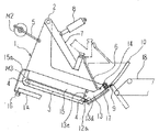
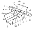
図面を参照しながら本発明を実施した食品スライサーについて説明する。図1は本発明に係る実施例の概略構成を示す側面図で、図2は図1に示す実施例における要部の斜視図である。 A food slicer embodying the present invention will be described with reference to the drawings. FIG. 1 is a side view showing a schematic configuration of an embodiment according to the present invention, and FIG. 2 is a perspective view of a main part in the embodiment shown in FIG.
本実施例は、本出願人が既に特願2007−098023として出願中である食品を斜め切りするスライサーをベースとするものであって、載置台1は、機台(図示省略)に設けられた支持軸2の軸心を中心として揺動可能に支持されている。 The present embodiment is based on a slicer that obliquely cuts food that the applicant has already filed as Japanese Patent Application No. 2007-098023, and the mounting table 1 is a support provided on a machine base (not shown). The shaft 2 is supported so as to be swingable about the axis of the shaft 2.
図1に示すように載置台1が支持軸2の軸心に対して非放射状方向に食品を送出すように配置され且つ、食品の先端部がバンドナイフによる切断面に対して斜めに接し食品を斜め切りする構成である。 As shown in FIG. 1, the mounting table 1 is disposed so as to feed food in a non-radial direction with respect to the axis of the support shaft 2, and the front end of the food is obliquely in contact with the cut surface by the band knife. It is the structure which cuts diagonally.
載置台1は、減速機付サーボモーターM2によって駆動されるクランク機構5に連結されていて少なくとも食品のスライスに必要な範囲(図1に実線で示す始端位置から一部のみの外形を仮想線で表示する終端位置)に亘り往復揺動するように構成されている。 The mounting table 1 is connected to a
載置台1の食品載置面には公知の送出コンベヤ3が設けられている。載置台1の送出始端部と終端部とのそれぞれにローラー4,4が軸支され、ローラー4,4に送出コンベヤ3が掛け回されている。始端部のローラー4には減速機付サーボモーターM3が連結されており、載置台1の揺動に関連して送出コンベヤ3は間欠的に駆動され送出コンベヤ3上に載置された食品を切断部に向けて送り出す。 A known
載置台1の送出し方向(図1の右方向)先端部には、先端面(バンドナイフ側面)が支持軸2の軸心を中心とした円弧状に形成された受刃枠12が設けられる。受刃枠12は、食品の通過口を囲う額縁状に形成され、巾方向の略中央部は隔壁13で仕切られている。
本実施例においては、隔壁13は一か所であるが特許文献1に開示されるように複数箇所であっても良い。A
In this embodiment, the
刃物が食品を切削していくとき食品が押し付けられる側の受刃枠12の構成部材即ち、本実施例においてはコンベヤ3の先端に位置する12aおよびバンドナイフの走行方向側(図2における矢印A側)に位置する12bと隔壁13のそれぞれの食品が押し付けられる面と刃物側の面とで形成されるエッジ部が受刃となる。 The constituent members of the receiving
これらの受刃とバンドナイフの刃先との間隙は少ない程切れ味が良いので、少なくとも食品がスライスされるときの切り終わり部(本実施例においては受刃枠12の構成部材12aと12bとで形成される隅角部Cおよび前記12aと隔壁13とで形成される隅角部C′である)付近においては受刃と刃先とは極力接近させるか、軽く接触させることが望ましい。 The smaller the gap between these receiving blades and the cutting edge of the band knife, the better the sharpness. Therefore, at least when the food is sliced (in this embodiment, formed by the
次に本願発明の要旨である受刃枠12に於ける隔壁13の着脱構成について図1、図2を用いて説明する。
隔壁13は板材を用いて、先端面(バンドナイフ側)は受刃枠12と同じ円弧状に形成される。この隔壁13を、受刃枠12との先端面を揃えるように受刃枠12の内側に嵌め込み組み付ける構成とする。Next, the attachment / detachment configuration of the
The
隔壁13の上端部には、受刃枠12の構成部材12cに接当して前後方向の位置決めを行うとともに隔壁13を前記12cにボルト14で締結するための取付板13aが形成される。この取付板13aにはガイドピン13bを設けて前記12cに開けられたガイド孔に挿入して左右方向の位置決めをする。 At the upper end of the
一方隔壁13の下端面には、突起13dが突設され受刃枠12の構成部材12aに削設されたガイド溝に嵌合されて位置決めされる。
上述のように構成された隔壁13は上述のような位置決め手段に従って受刃枠12に嵌め込まれた状態でボルト14を締め込み一体化する。On the other hand, a
The
隔壁13を受刃枠12に締結する手段は、本実施例のようにねじによるものに限らずレバーを使いワンタッチで両者を固着、開放できる各種締結器具を用いると便利である。 The means for fastening the
隔壁13の下部には、食品を案内するガイド板15との接合面13eが形成される。接合面13eには詳細の表示と説明は省くが位置決め用のノックピンが設けられている。 In the lower part of the
ガイド板15は隔壁13に設けられた接合面13eから反刃物側(図1の左側)の送出しコンベヤ3の始端部近く迄延設される。ガイド板15は、ガイド板15後端部から下方に延設された支持板15aの先端部を載置台1から延設された部材1aにねじ付きハンドル16によって取り付けられる。 The
上述のように構成された載置台1において、小形の食品をスライスしたいときには図1、図2に示す隔壁13およびガイド板15を取り付けた状態とし、より巾寸法の大きい食品をスライスしたいときにはガイド板15と隔壁13とを取り脱す。 In the mounting table 1 configured as described above, when the small food is to be sliced, the
ここでいう「より巾寸法の大きい食品」とは、食品の巾寸法が隔壁13で仕切られた受刃枠12の一方の食品通過口の巾寸法より大きく隔壁13を取り脱した状態の受刃枠12における食品の通過口の巾寸法より小さい食品である。 The “food with a larger width dimension” here means a receiving blade in a state where the width dimension of the food is larger than the width dimension of one food passage opening of the
上記小形の食品および、より巾寸法の大きい食品をスライスするとき、いずれの場合も食品の切り終わり部において、食品が受刃に押し付けられた状態でしかもバンドナイフの刃先と受刃との間隙が近接乃至接触して切削されるので確実にスライスすることができる。 When slicing the above-mentioned small foods and foods with a larger width, in any case, the gap between the cutting edge of the band knife and the receiving blade is maintained at the end of the food while the food is pressed against the receiving blade. Since it is cut close to or in contact, it can be sliced reliably.
尚、隔壁13とガイド板15とは一体に形成しても良いが、取り脱してから再び取り着けた際に先端部と刃先との間隙の維持が難しいので、より巾寸法の大きい食品をスライスする場合にのみ隔壁13を取り脱すことが可能な構成が望ましい。 The
載置台1には、載置された食品が少なくとも後述のバンドナイフによりスライスされるときに食品のスライス面近くを送出コンベヤ3に向けて押圧する公知の押圧具6が設けられる。
押圧具6は食品の上面を押圧できる巾寸法を有した板材で形成され載置台1の支持軸2に回動可能に支持された揺動アーム7に着脱自在に取り付けられている。
揺動アーム7には、取り付け状態は図示しないが一端が載置台1に取り付けられたエアーシリンダー8が連結され載置台1の揺動に関連して押圧具6が食品を押圧する構成とされる。The mounting table 1 is provided with a known pressing tool 6 that presses the vicinity of the sliced surface of the food toward the
The pressing tool 6 is formed of a plate material having a width that can press the upper surface of the food, and is detachably attached to a swing arm 7 that is rotatably supported by the support shaft 2 of the mounting table 1.
Although not shown, the swing arm 7 is connected to an air cylinder 8 having one end attached to the mounting table 1, and the pressing tool 6 presses the food in association with the swinging of the mounting table 1. .
載置台1の先端部の上方位置には公知のバンドナイフ9が設けられている。バンドナイフ9は機台(図示なし)に取付けられた溝付の刃受板10の溝に刃先を残してはめ込まれて案内される。
機台の左右には一対のプーリー11、11が備えられ一方のプーリーには減速機付モーターM1が連結されプーリー11、11に巻回されたバンドナイフ9は載置台1の往復揺動に関係なく予め設定された定速度で回転される。A known
A pair of pulleys 11 and 11 are provided on the left and right sides of the machine base. A motor M1 with a speed reducer is connected to one pulley, and the
また、載置台1が往復揺動の始端位置にあるときに、載置台1の食品送出口には当板17が設けられ食品の先端を受け止め、公知の手段によって送出し方向に移動可能とされスライス厚みが決められる。 Further, when the mounting table 1 is at the start position of the reciprocating swing, the food delivery outlet of the mounting table 1 is provided with an abutment plate 17 to receive the front end of the food and move in the feeding direction by known means. Slice thickness is determined.
バンドナイフ9の刃先と当板17の端部とに間に形成されるスライスされた食品の切出し口の直下には、始端部を臨ませスライス片を受け取る公知の搬出コンベヤ18が設けられる。図1においては始端部の一部のみが表示されている。
搬出コンベヤ18は、図示しない減速機付サーボモーターに連結され載置台1の往復揺動に関連して走行するよう駆動される。A known carry-out
The carry-out
上述のように本実施例においては定位置にあるバンドナイフに対して載置台を移動させて食品をスライスする形態としたが、逆に載置台を定位置に置き、なた刃など回転刃物で食品をスライスするものであっても良い。 As described above, in this embodiment, the food table is sliced by moving the mounting table with respect to the band knife in a fixed position. The food may be sliced.
1 載置台
3 送出コンベヤ
9 バンドナイフ
12 受刃枠
13 隔壁
15 ガイド板DESCRIPTION OF SYMBOLS 1
Claims (2)
Priority Applications (1)
| Application Number | Priority Date | Filing Date | Title |
|---|---|---|---|
| JP2007171192A JP4719829B2 (en) | 2007-06-01 | 2007-06-01 | Food slicer |
Applications Claiming Priority (1)
| Application Number | Priority Date | Filing Date | Title |
|---|---|---|---|
| JP2007171192A JP4719829B2 (en) | 2007-06-01 | 2007-06-01 | Food slicer |
Publications (2)
| Publication Number | Publication Date |
|---|---|
| JP2008296357A JP2008296357A (en) | 2008-12-11 |
| JP4719829B2 true JP4719829B2 (en) | 2011-07-06 |
Family
ID=40170356
Family Applications (1)
| Application Number | Title | Priority Date | Filing Date |
|---|---|---|---|
| JP2007171192A Active JP4719829B2 (en) | 2007-06-01 | 2007-06-01 | Food slicer |
Country Status (1)
| Country | Link |
|---|---|
| JP (1) | JP4719829B2 (en) |
Families Citing this family (1)
| Publication number | Priority date | Publication date | Assignee | Title |
|---|---|---|---|---|
| JP5769162B2 (en) * | 2010-03-19 | 2015-08-26 | 株式会社アイホー | Food cutting device |
Family Cites Families (2)
| Publication number | Priority date | Publication date | Assignee | Title |
|---|---|---|---|---|
| JPH10315187A (en) * | 1997-05-21 | 1998-12-02 | Tenryu Technic:Kk | External placing type tape cutter device for electric parts mounting machine |
| JP4224558B2 (en) * | 2002-04-24 | 2009-02-18 | 株式会社日本キャリア工業 | Block meat slicer |
-
2007
- 2007-06-01 JP JP2007171192A patent/JP4719829B2/en active Active
Also Published As
| Publication number | Publication date |
|---|---|
| JP2008296357A (en) | 2008-12-11 |
Similar Documents
| Publication | Publication Date | Title |
|---|---|---|
| KR20160144054A (en) | Meat cutter's fixing device | |
| JP2003501283A5 (en) | ||
| JP5455207B2 (en) | Rubber cutting device for conveyor belt and rubber cutting method | |
| JP4719829B2 (en) | Food slicer | |
| KR102147137B1 (en) | Reciprocating sawing band saw machine using two band saws | |
| JP2001088087A (en) | Vertically reciprocating slicer | |
| JP2008018500A (en) | Meat slicer | |
| JP5020266B2 (en) | Food slicer | |
| CN107020514A (en) | The automatic slicing sheet clipping machine of one discharge plate welding equipment material base bar | |
| JP4379868B2 (en) | Method and apparatus for adjusting slice thickness in an oscillating meat slicer | |
| JP4264591B2 (en) | Block meat slicer | |
| JP4724821B2 (en) | Meat slicer | |
| JP2009160684A (en) | Meat slicer | |
| JP2006224262A (en) | Meat slicer | |
| JP2005118947A (en) | Meat slicer | |
| JP2000141287A (en) | Guide device for strip blade in meat slicer | |
| JPH11123696A (en) | Food slicer | |
| JP3075664U (en) | Vertical reciprocating slicer | |
| JP5067923B2 (en) | Diagonal slice slicer | |
| CN210732569U (en) | Duck sawing machine | |
| JP4942464B2 (en) | Meat slicer | |
| JP2004338052A (en) | Meat slicer | |
| JP3360561B2 (en) | Meat slicer table | |
| JPH028718Y2 (en) | ||
| JPH0329119Y2 (en) |
Legal Events
| Date | Code | Title | Description |
|---|---|---|---|
| A871 | Explanation of circumstances concerning accelerated examination |
Free format text: JAPANESE INTERMEDIATE CODE: A871 Effective date: 20100521 |
|
| A621 | Written request for application examination |
Free format text: JAPANESE INTERMEDIATE CODE: A621 Effective date: 20100521 |
|
| A975 | Report on accelerated examination |
Free format text: JAPANESE INTERMEDIATE CODE: A971005 Effective date: 20100702 |
|
| A977 | Report on retrieval |
Free format text: JAPANESE INTERMEDIATE CODE: A971007 Effective date: 20100917 |
|
| A131 | Notification of reasons for refusal |
Free format text: JAPANESE INTERMEDIATE CODE: A131 Effective date: 20100928 |
|
| A521 | Request for written amendment filed |
Free format text: JAPANESE INTERMEDIATE CODE: A523 Effective date: 20101012 |
|
| TRDD | Decision of grant or rejection written | ||
| A01 | Written decision to grant a patent or to grant a registration (utility model) |
Free format text: JAPANESE INTERMEDIATE CODE: A01 Effective date: 20101130 |
|
| A61 | First payment of annual fees (during grant procedure) |
Free format text: JAPANESE INTERMEDIATE CODE: A61 Effective date: 20101215 |
|
| FPAY | Renewal fee payment (event date is renewal date of database) |
Free format text: PAYMENT UNTIL: 20140415 Year of fee payment: 3 |
|
| R150 | Certificate of patent or registration of utility model |
Ref document number: 4719829 Country of ref document: JP Free format text: JAPANESE INTERMEDIATE CODE: R150 Free format text: JAPANESE INTERMEDIATE CODE: R150 |
|
| FPAY | Renewal fee payment (event date is renewal date of database) |
Free format text: PAYMENT UNTIL: 20140415 Year of fee payment: 3 |
|
| R250 | Receipt of annual fees |
Free format text: JAPANESE INTERMEDIATE CODE: R250 |
|
| R250 | Receipt of annual fees |
Free format text: JAPANESE INTERMEDIATE CODE: R250 |
|
| R250 | Receipt of annual fees |
Free format text: JAPANESE INTERMEDIATE CODE: R250 |
|
| R250 | Receipt of annual fees |
Free format text: JAPANESE INTERMEDIATE CODE: R250 |
|
| R250 | Receipt of annual fees |
Free format text: JAPANESE INTERMEDIATE CODE: R250 |
|
| R250 | Receipt of annual fees |
Free format text: JAPANESE INTERMEDIATE CODE: R250 |
|
| R250 | Receipt of annual fees |
Free format text: JAPANESE INTERMEDIATE CODE: R250 |
|
| R250 | Receipt of annual fees |
Free format text: JAPANESE INTERMEDIATE CODE: R250 |
|
| R250 | Receipt of annual fees |
Free format text: JAPANESE INTERMEDIATE CODE: R250 |
|
| R250 | Receipt of annual fees |
Free format text: JAPANESE INTERMEDIATE CODE: R250 |
|
| R250 | Receipt of annual fees |
Free format text: JAPANESE INTERMEDIATE CODE: R250 |
|
| R250 | Receipt of annual fees |
Free format text: JAPANESE INTERMEDIATE CODE: R250 |
|
| R250 | Receipt of annual fees |
Free format text: JAPANESE INTERMEDIATE CODE: R250 |