JP2015124504A - Elevator type parking device - Google Patents
Elevator type parking device Download PDFInfo
- Publication number
- JP2015124504A JP2015124504A JP2013268473A JP2013268473A JP2015124504A JP 2015124504 A JP2015124504 A JP 2015124504A JP 2013268473 A JP2013268473 A JP 2013268473A JP 2013268473 A JP2013268473 A JP 2013268473A JP 2015124504 A JP2015124504 A JP 2015124504A
- Authority
- JP
- Japan
- Prior art keywords
- parking
- hoistway
- traverse
- vehicle
- storage tray
- Prior art date
- Legal status (The legal status is an assumption and is not a legal conclusion. Google has not performed a legal analysis and makes no representation as to the accuracy of the status listed.)
- Pending
Links
Images


Abstract
Description
本発明は、車両を立体的に格納するエレベータ式駐車装置に関する。 The present invention relates to an elevator-type parking apparatus that three-dimensionally stores a vehicle.
立体駐車装置は、スペースの少ない土地に多数の車両を効率よく駐車できる駐車設備として住宅密集地等において広く利用されており、利用する土地の広狭や経済性などを考慮した種々の構造のものが提供されている。この立体駐車装置の機種の一つとして、上下多段に配置された複数の駐車室に沿ってエレベータを昇降させ、各駐車室とエレベータとの間で車両を受け渡しするエレベータ式駐車装置がある。 3D parking devices are widely used in densely populated houses as parking facilities that can efficiently park a large number of vehicles on land with little space, and have various structures that take into account the size and economics of the land used. Is provided. As one type of this three-dimensional parking apparatus, there is an elevator type parking apparatus that lifts and lowers an elevator along a plurality of parking rooms arranged in multiple upper and lower stages, and delivers a vehicle between each parking room and the elevator.
このエレベータ式駐車装置には、パレット上に車両を搭載してエレベータで搬送し、このパレットごと車両を駐車室との間で受け渡しするパレット方式と、このようなパレットを用いることなく車両のみを受け渡しするパレットレス方式とがある。パレット方式は、駐車室とエレベータの昇降機との間でパレットないし車両を横行駆動する駆動装置を昇降機に備えており、このために各駐車室の構造が簡素であって、装置全体の設備費を安価にできる。その一方、パレット方式は、入庫に際しては空のパレットを引き出すために昇降機を当該駐車室まで移動させる必要があり、また、出庫に際しては空となったパレットを当該駐車室まで移送する必要があるため、入出庫に際して時間を要するという短所がある。 In this elevator type parking apparatus, a vehicle is mounted on a pallet and transported by an elevator, and the pallet system that delivers the vehicle to and from the parking room together with the pallet, and only the vehicle is delivered without using such a pallet. There is a pallet-less method. The pallet system is equipped with a driving device for traversing the pallet or vehicle between the parking room and the elevator elevator, so that the structure of each parking room is simple and the equipment cost of the entire apparatus is reduced. Can be cheap. On the other hand, in the pallet system, it is necessary to move the elevator to the parking room in order to pull out an empty pallet when entering the warehouse, and it is necessary to transfer the pallet that has been emptied to the parking room when leaving the warehouse. There is a disadvantage that it takes time to enter and exit.
パレットを用いないパレットレス方式のエレベータ式駐車装置は、車両を搭載する部分を櫛歯とした装置が従来より多数採用されており、この装置は概略以下のように構成されている。まず、車両を搭載してエレベータの昇降路を上下に移動する昇降機は、車両を搭載する部分が櫛歯で形成されている。昇降路に沿って複数階に設けられた各駐車室には、昇降路内へ水平移動自在に格納トレイを備えており、この格納トレイは各駐車室に備えた横行駆動装置により駆動されて駐車室内と昇降路との間を移動する。格納トレイの車両を搭載する部分は、昇降機の櫛歯と互い違いに配置された櫛歯で形成されており、昇降路内で格納トレイと昇降機とが上下に交差して通り抜けることで車両が相互に受け渡される。 A pallet-less type elevator parking device that does not use a pallet has conventionally adopted a number of devices in which a portion on which the vehicle is mounted is comb-toothed, and this device is generally configured as follows. First, in an elevator that mounts a vehicle and moves up and down the elevator hoistway, a portion on which the vehicle is mounted is formed by comb teeth. Each parking room provided on multiple floors along the hoistway is equipped with a storage tray that can move horizontally into the hoistway, and this storage tray is driven by a traverse drive device provided in each parking room for parking. Move between the room and the hoistway. The portion of the storage tray on which the vehicle is mounted is formed by comb teeth that are alternately arranged with the comb teeth of the elevator. The storage tray and the elevator cross each other in the hoistway so that the vehicles pass each other. Delivered.
このようなパレットレス方式のエレベータ式駐車装置は、入出庫に要する時間は比較的短いものの、上記したように各駐車室には格納トレイを駆動する横行駆動装置を設ける必要があり、車両の収容台数を多く設定する毎に製作コストや電気工事費等の生産コストが高くなるとともに、メンテナンスが繁雑であるという短所がある。このような課題を解決する従来技術として、特許文献1に記載の技術が提案されている。
Although such a palletless type elevator parking device requires a relatively short time for entry and exit, it is necessary to provide a traverse drive device for driving a storage tray in each parking room as described above. Each time a large number of units are set, production costs such as production costs and electrical work costs increase, and there are disadvantages that maintenance is complicated. As a conventional technique for solving such a problem, a technique described in
特許文献1に記載の駐車装置は、概略以下のように構成されている。駐車棚(駐車室)内には、鉛直面内で矩形状に旋回するように無端チェーンを掛け回し、駆動モータにより旋回駆動される。無端チェーンには、係合部材が取り付けられており、この係合部材は当該駐車棚の車両搭載架台(格納トレイ)と、直上階の駐車棚の車両搭載架台とに係合するようになっている。無端チェーンを駆動すると、無端チェーンの旋回方向により当該階又は直上階の車両搭載架台が選択的に昇降路方向へ搬送される。このときに車両搭載架台は、昇降路の中央位置まで搬送されず、わずかに駐車棚側に戻った位置にとどまる。次に、エレベータには、鉛直面内で略く字形状の横行ガイド部材を備えており、エレベータの昇降にともなってこの横行ガイド部材が車両搭載架台の係合部材に係合するとともに、車両搭載架台を昇降路の中央位置まで引き出す。
The parking apparatus described in
上記特許文献1に記載された駐車装置は、上下2カ所の駐車棚(駐車室)に付き1台の横行駆動装置を設ければよいので、従来の駐車装置に比して生産コストを低減できるものの、依然として複数の横行駆動装置を必要とすることから、車両の収容台数を多く設定する毎に生産コストが高くなるとともに、メンテナンスも繁雑になってしまう。
Since the parking device described in the above-mentioned
本発明は、このような事情に鑑みてなされたものであって、各駐車室に備える格納トレイを横行させる横行駆動装置の数を減少させ、これによって設備費を低減するとともにメンテナンスが容易となり、また、入出庫階が中間又は上部に設けられていても車両の旋回を行って方向転換を行うことのできる、エレベータ式駐車装置を提供することを目的としている。 The present invention has been made in view of such circumstances, and reduces the number of traversing drive devices that traverse the storage tray provided in each parking room, thereby reducing equipment costs and facilitating maintenance. It is another object of the present invention to provide an elevator parking apparatus that can turn a vehicle and change direction even if an entry / exit floor is provided in the middle or upper part.
上記課題を解決するために本発明は、上下方向に貫通する空間を有する昇降路と、該昇降路に沿って上下多段に設けられた駐車室と、該駐車室に横行自在に配置され、車両の搭載部を櫛歯状に形成された格納トレイと、車両の搭載部を前記格納トレイの櫛歯と交互になるように櫛歯状に形成し、前記昇降路を昇降するケージと、該ケージの前方及び後方の位置で昇降路を昇降する横行装置と、入出庫階の直下の階層に横行自在に配置された旋回装置と、を備え、前記横行装置には、前記格納トレイを横行自在に支持する横行レールと、前記格納トレイ及び前記旋回装置を前記駐車室と前記横行レール上との間で横行させる横行駆動装置と、を備えたことを特徴としている。 In order to solve the above-described problems, the present invention provides a hoistway having a space penetrating in the vertical direction, a parking room provided in multiple upper and lower stages along the hoistway, A storage tray formed in a comb-teeth shape, a cage in which a vehicle mounting portion is formed in a comb-teeth shape so as to alternate with the comb teeth of the storage tray, and a cage that moves up and down the hoistway, and the cage A traverse device that ascends and descends the hoistway at the front and rear positions, and a swivel device that is disposed so as to be traversable at a level immediately below the loading / unloading floor, wherein the traverse device is configured to traverse the storage tray. A traversing rail to be supported, and a traverse drive device for traversing the storage tray and the turning device between the parking chamber and the traversing rail are provided.
本発明によれば、横行レールと横行駆動装置を備えた横行装置を昇降させて、該当する駐車室との間で収納パレットの受け渡しを行うようにしたことにより、各駐車室毎に横行駆動装置を設ける必要が無く、設備に要する費用を低減することができ、また横行駆動装置等のメンテナンスも容易になる。また、入出庫階の直下の階層に旋回装置を横行自在に備えたことにより、これを昇降路へ移動させて車両を旋回させることができる。 According to the present invention, the traversing device provided with the traversing rail and the traversing drive device is moved up and down, and the storage pallet is transferred to and from the corresponding parking chamber. It is not necessary to provide an additional cost, and the cost required for the facility can be reduced, and maintenance of the traverse drive device and the like is facilitated. In addition, since the swivel device is provided so as to be able to traverse the floor immediately below the entry / exit floor, the vehicle can be swung by moving it to the hoistway.
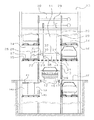
以下、本発明の具体的な実施の形態を図面を参照して説明する。図1及び図2は、エレベータ式駐車装置の概略を示す正面図及び平面図である。尚、以降の説明においては、特に説明の無いかぎり、駐車する車両の前後方向を装置の前後方向とし、車両の左右方向を装置の左右方向として説明する。 Hereinafter, specific embodiments of the present invention will be described with reference to the drawings. FIG.1 and FIG.2 is the front view and top view which show the outline of an elevator-type parking apparatus. In the following description, unless otherwise specified, the front-rear direction of the parked vehicle will be referred to as the front-rear direction of the apparatus, and the left-right direction of the vehicle will be described as the left-right direction of the apparatus.
エレベータ式駐車装置10の内部には、中央を上下に貫通する昇降路11が形成されており、この昇降路11を昇降可能にケージ12を設けている。昇降路11の四隅には、ケージ12を案内するガイドレール13が立設されており、ケージ12はこれに沿って垂直方向へ昇降する。昇降路11の両側方には、複数の駐車室14が上下多段に形成されており、各駐車室14には、それぞれ車両16を搭載して格納するための格納トレイ15を備えている。エレベータ式駐車装置10の上下方向中間位置又は最上部位置(図示せず)は、車両16が入退出する入出庫階37となっている。
Inside the
図2に示すように、格納トレイ15は、前端部と後端部において水平に延びる横フレーム25と、両横フレーム25の中央部間を連結する縦フレーム26とを有しており、この縦フレーム26の前部および後部には、両側方に向けて櫛歯状のトレイフォーク27が形成されている。各駐車室14には、横フレーム25の下方位置に複数の横行ローラー21を配置して備えており、これにより格納トレイ15は駐車室14内で横行自在に支持されている。
As shown in FIG. 2, the
前記ケージ12は左右一対で構成されており、左右各々の両端部で前後方向へ延びるサイドフレーム17と、これらのサイドフレーム17の内側に櫛歯状に一体形成されて車両16の各前後車輪を支持するケージフォーク18とを備えている。このケージフォーク18の櫛歯と前記格納トレイ15に形成されたトレイフォーク27の櫛歯とは、平面視において重なり合ったときに互い違いとなるように形成されており、互いに上下方向へすれ違うことが可能となっている。前記各サイドフレーム17の前後端部は、垂直方向に張架された四本の索条20に連結されており、この索条20を昇降路11の上部に備えたケージ駆動装置38によって同期して駆動することにより、ケージ12が昇降路11内を昇降移動する。また、各サイドフレーム17の前後端部には、それぞれガイドローラー19を回転自在に軸支し、このガイドローラー19がガイドレール13に案内されてケージ12が昇降路11内を昇降する。
The
ケージ12の前方と後方の位置には、横行装置22が配設されている。この横行装置22は、横行ローラー21を複数備えた横行レール23と、駐車室14に備えた格納トレイ15を横行駆動する横行駆動装置24とを備えており、横行駆動装置24を動作させることにより、駐車室14と横行装置22上との間で格納トレイ15の受け渡しが行われる。横行装置22は、垂直方向に張架されたチェーン28に連結されており、このチェーン28を昇降路11の上部に備えた昇降駆動装置29によって駆動することにより、横行装置22が昇降路11内を昇降移動する。
A traversing
横行駆動装置24は、横行レール23の両側端部の上方に回転自在に備えたスプロケット30、31と、一のスプロケット30を回転駆動する駆動機36と、両スプロケット30、31間に無端状に巻き掛けたチェーン32と、このチェーン32の外周に取り付けた押送ロッド33とを備えている。押送ロッド33はL字形状に形成された部材であり、チェーン32に固着した位置から外周方向へ突出するとともに、先端部を昇降路11内側方向へ突出させて、ここに押送ローラー34を備えている。一方、格納トレイ15の横フレーム25の昇降路11側には、上方に突出した係合部35を備えている。この係合部35には、上端が開口して下方へ延びた溝が形成されており、この溝に上記押送ローラー34が係合する。
The
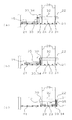
図3は、横行駆動装置24及び格納トレイ15の動作を模式的に示した説明図である。図3(a)において、点線で示した押送ロッド33が直立した状態から、駆動機36によりスプロケット30を回転させてチェーン32を反時計方向に循環移動させると、押送ロッド33が水平となった位置で押送ローラー34が係合部35の溝に係合する。引き続きチェーン32が循環移動すると、図3(b)に示すように押送ローラー34が係合部35の溝内を下降し、これにともなって格納トレイ15が横行装置22側へ引き寄せられる。次いで、チェーン32の移動とともに押送ロッド33が進行すると、格納トレイ15が横行レール23に乗り移り、図3(c)に示すように、格納トレイ15全体が横行レール23上に乗り移ると横行駆動装置24が停止する。格納トレイ15を横行レール23上から駐車室14に移動させる場合には、上記の動作と反対の動作を行う。
FIG. 3 is an explanatory view schematically showing the operation of the
次に、図1に示すように入出庫階37直下の駐車室14aには、駐車室14aと昇降路11との間を横行自在に旋回装置39を備えている。この旋回装置39の上部には、上下動が可能であり、また、平面方向に回動可能なターンテーブル40を備えており、後述するように、このターンテーブル40に車両16を搭載して方向転換を行う。また、このターンテーブル40は、昇降路11に位置したときに入出庫階37の昇降路11開口部を閉鎖する形状をなすとともに、ケージ12が上下にすり抜けるようにケージ12との交差する部分は櫛歯状となっている。この旋回装置39の昇降路11側には、格納トレイ15と同様に係合部35を備えており、格納トレイ15と同様に横行駆動装置24によって駐車室14aと昇降路11との間を横行駆動される。
Next, as shown in FIG. 1, the
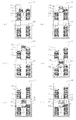
以上の構成により、まず、エレベータ式駐車装置10に格納した車両16を出庫させる場合を図4により説明する。まず、エレベータ式駐車装置10の操作盤により出庫する車両16を指定すると、図4(a)に示すように、横行装置22は該当する車両16の駐車室14まで昇降路11を移動して停止し、この後、押送駆動装置24が動作して車両16を搭載した格納トレイ15を横行レール23上へ移動させる。これと並行してケージ12も当該駐車室14付近まで移動するが、この際にケージ12は横行装置22よりも下方に位置するようになっている。
First, the case where the
図4(b)に示すように、格納トレイ15の移動が完了するとケージ12が上昇し、格納トレイ15を通り抜けると同時に車両16が格納トレイ15からケージ12へと受け渡され、その後ケージ12は、横行装置22から若干上昇した位置で一旦停止する。次に図4(c)に示すように、横行装置22の横行駆動装置24が動作して、横行レール23上の格納トレイ15を駐車室14側へ移動させる。
As shown in FIG. 4B, when the movement of the
格納トレイ15が完全に駐車室14に格納されると、図4(d)に示すようにケージ12と横行装置22とは昇降路11を下降し、ケージ12が入出庫階37で停止するとともに、横行装置22は、その1階層下段で停止して上記と同様の動作により旋回装置39を昇降路11側へ移動させる。続いて、図4(e)に示すように旋回装置39が昇降路11内へ移動して停止すると、旋回装置39のターンテーブル40が上昇してケージ12を通り抜けて車両16がターンテーブル40に受け渡され、さらにターンテーブル40は若干上昇した位置で停止する。
When the
この後、ターンテーブル40が水平方向へ180度回転して車両16の前面を入出庫口41に対向させ、続いて、ターンテーブル40が下降してケージ12と重なり合う位置で停止する(図4(f))。このときターンテーブル40の上面とケージ12の上面とは、略面一となって昇降路11の開口部を塞ぎ、車両16の走行路を形成する。続いて、車両16の運転者が車両16に乗り込み、入出庫口41から車両16を前進で退出させる。
Thereafter, the
次に、図5によって車両16を入庫する場合を説明する。エレベータ式駐車装置10の入出庫階37には、ケージ12が予め待機するとともに、旋回装置39が昇降路11内に位置してターンテーブル40を上昇させ、ケージ12の上面とターンテーブル40との上面が略面一となって昇降路11の開口部を塞いでいる。入庫する車両16は自走によりケージ12及びターンテーブル40上に乗り込み停止する(図5(a))。運転者が装置内から退室すると、旋回装置39のターンテーブル40が下降し、次いで横行装置22により旋回装置39を駐車室14aへ移動させる(図5(b))。
Next, a case where the
続いて、ケージ12と横行装置22とが下降して、横行装置22が所定の駐車室14の位置に停止するとともに、ケージ12が所定の位置よりも若干上方の位置で停止する(図5(c))。次に、横行装置22の横行駆動装置24が動作して、格納トレイ15を駐車室14から昇降路11へ移動させた後、ケージ12が下降して車両16がケージ12から格納トレイ15へ受け渡される(図5(d))。次いで、横行装置22が動作して、格納トレイ15及び車両16が駐車室14内に格納される(図5(e))。
Subsequently, the
以上説明したように、本発明のエレベータ式駐車装置10は、昇降路11の前方と後方に横行装置22を昇降自在に備え、この横行装置22には、格納トレイ15を支持する横行レール23と、格納トレイ15を駐車室14と横行レール23との間で移動させる横行駆動装置24とを備えた。そして、この横行装置22を該当する駐車室14へ移動させて格納トレイ15の出し入れを行うようにしたので、格納トレイ15を横行させる駆動装置を各駐車室14毎に設ける必要がない。また、車両16を旋回させる旋回装置39を入出庫階37の直下の階層に横行自在に備え、これを横行装置22により横行駆動して昇降路11に配置して入出庫階37で車両16を旋回させるようにしたことにより、入出庫階37が中間又は上部に設けられたエレベータ式駐車装置10であっても車両16の旋回が可能になる。
As described above, the
10 エレベータ式駐車装置
11 昇降路
12 ケージ
13 ガイドレール
14 駐車室
14a 駐車室
15 格納トレイ
16 車両
17 サイドフレーム
18 ケージフォーク
19 ガイドローラー
20 索条
21 横行ローラー
22 横行装置
23 横行レール
24 横行駆動装置
25 横フレーム
26 縦フレーム
27 トレイフォーク
28 チェーン
29 昇降駆動装置
30 スプロケット
31 スプロケット
32 チェーン
33 押送ロッド
34 押送ローラー
35 係合部
36 駆動機
37 入出庫階
38 ケージ駆動装置
39 旋回装置
40 ターンテーブル
41 入出庫口
DESCRIPTION OF
Claims (1)
Priority Applications (1)
| Application Number | Priority Date | Filing Date | Title |
|---|---|---|---|
| JP2013268473A JP2015124504A (en) | 2013-12-26 | 2013-12-26 | Elevator type parking device |
Applications Claiming Priority (1)
| Application Number | Priority Date | Filing Date | Title |
|---|---|---|---|
| JP2013268473A JP2015124504A (en) | 2013-12-26 | 2013-12-26 | Elevator type parking device |
Publications (1)
| Publication Number | Publication Date |
|---|---|
| JP2015124504A true JP2015124504A (en) | 2015-07-06 |
Family
ID=53535426
Family Applications (1)
| Application Number | Title | Priority Date | Filing Date |
|---|---|---|---|
| JP2013268473A Pending JP2015124504A (en) | 2013-12-26 | 2013-12-26 | Elevator type parking device |
Country Status (1)
| Country | Link |
|---|---|
| JP (1) | JP2015124504A (en) |
Cited By (2)
| Publication number | Priority date | Publication date | Assignee | Title |
|---|---|---|---|---|
| CN107246169A (en) * | 2017-02-15 | 2017-10-13 | 广东明和智能设备有限公司 | A kind of control system and control method of parking systems automatically storing and taking vehicles |
| CN111764716A (en) * | 2020-06-26 | 2020-10-13 | 温州市简弈科技有限公司 | Multi-angle three-dimensional parking lot |
Citations (3)
| Publication number | Priority date | Publication date | Assignee | Title |
|---|---|---|---|---|
| US5505573A (en) * | 1994-12-29 | 1996-04-09 | Han; Tai-Kang | Parking tower |
| JPH11324383A (en) * | 1998-05-21 | 1999-11-26 | Fuji Hensokuki Co Ltd | Storing apparatus |
| JP2009036000A (en) * | 2007-07-31 | 2009-02-19 | Fuji Hensokuki Co Ltd | Turntable of parking tower |
-
2013
- 2013-12-26 JP JP2013268473A patent/JP2015124504A/en active Pending
Patent Citations (3)
| Publication number | Priority date | Publication date | Assignee | Title |
|---|---|---|---|---|
| US5505573A (en) * | 1994-12-29 | 1996-04-09 | Han; Tai-Kang | Parking tower |
| JPH11324383A (en) * | 1998-05-21 | 1999-11-26 | Fuji Hensokuki Co Ltd | Storing apparatus |
| JP2009036000A (en) * | 2007-07-31 | 2009-02-19 | Fuji Hensokuki Co Ltd | Turntable of parking tower |
Cited By (2)
| Publication number | Priority date | Publication date | Assignee | Title |
|---|---|---|---|---|
| CN107246169A (en) * | 2017-02-15 | 2017-10-13 | 广东明和智能设备有限公司 | A kind of control system and control method of parking systems automatically storing and taking vehicles |
| CN111764716A (en) * | 2020-06-26 | 2020-10-13 | 温州市简弈科技有限公司 | Multi-angle three-dimensional parking lot |
Similar Documents
| Publication | Publication Date | Title |
|---|---|---|
| JP2015135029A (en) | Elevator type parking device | |
| KR100453147B1 (en) | Automatic moving system and method for parking vehicle using comb | |
| JP6284324B2 (en) | Elevator parking system | |
| JP2015074894A (en) | Elevator type parking device | |
| JP6327872B2 (en) | Elevator parking device traversing device | |
| KR100310446B1 (en) | Multi-story parking facility | |
| JP2015124504A (en) | Elevator type parking device | |
| JP5206827B2 (en) | Mechanical bicycle parking equipment and method | |
| JP6533086B2 (en) | Fork type parking device and its operating method | |
| JP5753723B2 (en) | Two-stage parking system and its entry / exit method | |
| JP6133062B2 (en) | Multistage parking system | |
| JP5653134B2 (en) | Simultaneous elevator type parking system | |
| JP6306324B2 (en) | Elevator type parking device vehicle transfer device | |
| JP4058684B2 (en) | High-rise multilevel parking system | |
| JP2001065185A (en) | Mechanical parking equipment | |
| JP5787229B2 (en) | Shelf-type bicycle parking facilities | |
| JP4415500B2 (en) | Pallet storage device | |
| JP7427751B2 (en) | Mechanical parking device and its control method | |
| JP4341567B2 (en) | Boarding floor of parking equipment | |
| JP2880115B2 (en) | Mechanical parking lot | |
| JP6765852B2 (en) | Horizontal simultaneous fork parking and its entry / exit method | |
| JP2009270252A (en) | Elevator type parking apparatus | |
| JP4369823B2 (en) | Elevator parking system | |
| JP4065633B2 (en) | Mechanical parking equipment | |
| JP6448907B2 (en) | Overhead type transport storage device and automatic storage / removal type material storage |
Legal Events
| Date | Code | Title | Description |
|---|---|---|---|
| A621 | Written request for application examination |
Free format text: JAPANESE INTERMEDIATE CODE: A621 Effective date: 20161222 |
|
| RD03 | Notification of appointment of power of attorney |
Free format text: JAPANESE INTERMEDIATE CODE: A7423 Effective date: 20161222 |
|
| A977 | Report on retrieval |
Free format text: JAPANESE INTERMEDIATE CODE: A971007 Effective date: 20171012 |
|
| A131 | Notification of reasons for refusal |
Free format text: JAPANESE INTERMEDIATE CODE: A131 Effective date: 20171128 |
|
| A521 | Request for written amendment filed |
Free format text: JAPANESE INTERMEDIATE CODE: A523 Effective date: 20171222 |
|
| A02 | Decision of refusal |
Free format text: JAPANESE INTERMEDIATE CODE: A02 Effective date: 20180508 |