JP2015123772A - Pneumatic tire - Google Patents
Pneumatic tire Download PDFInfo
- Publication number
- JP2015123772A JP2015123772A JP2013267544A JP2013267544A JP2015123772A JP 2015123772 A JP2015123772 A JP 2015123772A JP 2013267544 A JP2013267544 A JP 2013267544A JP 2013267544 A JP2013267544 A JP 2013267544A JP 2015123772 A JP2015123772 A JP 2015123772A
- Authority
- JP
- Japan
- Prior art keywords
- groove
- pair
- side wall
- pneumatic tire
- tire
- Prior art date
- Legal status (The legal status is an assumption and is not a legal conclusion. Google has not performed a legal analysis and makes no representation as to the accuracy of the status listed.)
- Pending
Links
Images


Classifications
-
- Y—GENERAL TAGGING OF NEW TECHNOLOGICAL DEVELOPMENTS; GENERAL TAGGING OF CROSS-SECTIONAL TECHNOLOGIES SPANNING OVER SEVERAL SECTIONS OF THE IPC; TECHNICAL SUBJECTS COVERED BY FORMER USPC CROSS-REFERENCE ART COLLECTIONS [XRACs] AND DIGESTS
- Y02—TECHNOLOGIES OR APPLICATIONS FOR MITIGATION OR ADAPTATION AGAINST CLIMATE CHANGE
- Y02T—CLIMATE CHANGE MITIGATION TECHNOLOGIES RELATED TO TRANSPORTATION
- Y02T10/00—Road transport of goods or passengers
- Y02T10/80—Technologies aiming to reduce greenhouse gasses emissions common to all road transportation technologies
- Y02T10/86—Optimisation of rolling resistance, e.g. weight reduction
Landscapes
- Tires In General (AREA)
Abstract
Description
本発明は、主溝の深さを小さくして、トレッド部のゴムボリュームを削減することが可能な空気入りタイヤに関する。 The present invention relates to a pneumatic tire capable of reducing a rubber volume of a tread portion by reducing a depth of a main groove.
近年、低燃費性能を向上させるために、タイヤの転がり抵抗を低下させた空気入りタイヤが強く求められている。タイヤの転がり抵抗を低下させるには、タイヤのゴムボリュームを削減して、ゴムのエネルギーロスを減少させることが重要である(例えば、下記特許文献1参照)。 In recent years, pneumatic tires with reduced tire rolling resistance have been strongly demanded in order to improve fuel efficiency. In order to reduce the rolling resistance of a tire, it is important to reduce the rubber energy loss by reducing the rubber volume of the tire (see, for example, Patent Document 1 below).
タイヤのゴムボリュームを削減するために、例えば、主溝の溝深さを小さくして、トレッド部のゴムボリュームを小さくすることが有効である。しかしながら、主溝の溝深さを小さくすると、新品時から主溝の溝底が目立ちやすくなる。主溝の溝底が目立つと、タイヤが早期に摩耗するのではないか等の不安をユーザに与えてしまう問題があった。 In order to reduce the rubber volume of the tire, it is effective to reduce the rubber volume of the tread portion by reducing the groove depth of the main groove, for example. However, if the groove depth of the main groove is made small, the groove bottom of the main groove becomes more conspicuous from the time of a new article. When the groove bottom of the main groove is conspicuous, there is a problem that gives the user anxiety that the tire may be worn out early.
本発明は、以上のような実状に鑑み案出されたもので、主溝の深さを小さくして、トレッド部のゴムボリュームを削減することが可能な空気入りタイヤを提供することを主たる目的としている。 The present invention has been devised in view of the actual situation as described above, and it is a principal object of the present invention to provide a pneumatic tire capable of reducing the rubber volume of the tread portion by reducing the depth of the main groove. It is said.
本発明は、トレッド部に、タイヤ周方向にのびる少なくとも1本の主溝を具えた空気入りタイヤであって、前記主溝の最大溝深さは、6mm以上7mm以下であり、前記主溝は、その長手方向と直角な溝断面において、前記トレッド部の踏面からタイヤ半径方向内側にのびる一対の溝壁部と、前記一対の溝壁部の間の溝底部とを含み、前記溝底部は、タイヤ半径方向外側に隆起する突起部を含むことを特徴とする。 The present invention is a pneumatic tire having at least one main groove extending in a tire circumferential direction in a tread portion, wherein the maximum groove depth is 6 mm or more and 7 mm or less, and the main groove is A groove cross section perpendicular to the longitudinal direction includes a pair of groove wall portions extending inward in the tire radial direction from the tread surface of the tread portion, and a groove bottom portion between the pair of groove wall portions, It includes a protrusion that protrudes outward in the tire radial direction.
本発明に係る前記空気入りタイヤにおいて、前記突起部は、前記主溝の最大溝深さの25%〜42%の隆起高さを有するのが望ましい。 In the pneumatic tire according to the present invention, it is preferable that the protrusion has a raised height of 25% to 42% of the maximum groove depth of the main groove.
本発明に係る前記空気入りタイヤにおいて、前記溝断面において、前記突起部は、タイヤ半径方向外側にのびる一対の側壁面を含み、前記一対の側壁面は、タイヤ半径方向内側に向かって凸となる円弧で形成されているのが望ましい。 In the pneumatic tire according to the present invention, in the groove cross section, the protrusion includes a pair of side wall surfaces extending outward in the tire radial direction, and the pair of side wall surfaces are convex toward the inner side in the tire radial direction. It is desirable that the arc is formed.
本発明に係る前記空気入りタイヤにおいて、前記一対の側壁面は、前記突起部の頂点で交わっているのが望ましい。 In the pneumatic tire according to the present invention, it is desirable that the pair of side wall surfaces intersect at the apexes of the protrusions.
本発明に係る前記空気入りタイヤにおいて、前記一対の側壁面は、前記主溝の幅方向において、対称に形成されるのが望ましい。 In the pneumatic tire according to the present invention, it is desirable that the pair of side wall surfaces be formed symmetrically in the width direction of the main groove.
本発明に係る前記空気入りタイヤにおいて、前記一対の側壁面には、前記突起部の頂点から前記溝底部に向かってのび、かつ、前記主溝の長手方向に隔設される第1細溝が設けられるのが望ましい。 In the pneumatic tire according to the present invention, the pair of side wall surfaces have first narrow grooves extending from the apex of the protrusion toward the groove bottom and spaced apart in the longitudinal direction of the main groove. It is desirable to be provided.
本発明に係る前記空気入りタイヤにおいて、前記第1細溝の側壁面に沿った長さは、前記突起部の隆起高さの40%〜60%であるのが望ましい。 In the pneumatic tire according to the present invention, it is preferable that the length along the side wall surface of the first narrow groove is 40% to 60% of the raised height of the protrusion.
本発明に係る前記空気入りタイヤにおいて、前記溝断面において、前記一対の溝壁部は、前記溝底部に連なり、かつ、タイヤ半径方向内側に向かって凸となる円弧で形成された円弧面を有するのが望ましい。 In the pneumatic tire according to the present invention, in the groove cross section, the pair of groove wall portions have an arc surface formed by an arc that is continuous with the groove bottom portion and protrudes inward in the tire radial direction. Is desirable.
本発明に係る前記空気入りタイヤにおいて、前記一対の円弧面には、前記円弧面のタイヤ半径方向の外端から、前記溝底部に向かってのび、かつ、前記主溝の長手方向に隔設される第2細溝が設けられるのが望ましい。 In the pneumatic tire according to the present invention, the pair of arcuate surfaces are spaced from the outer ends of the arcuate surfaces in the tire radial direction toward the groove bottom and spaced apart in the longitudinal direction of the main groove. It is desirable to provide a second narrow groove.
本発明に係る前記空気入りタイヤにおいて、前記第2細溝の前記円弧面に沿った長さは、前記突起部の隆起高さの40%〜60%であるのが望ましい。 In the pneumatic tire according to the present invention, it is preferable that a length of the second narrow groove along the arc surface is 40% to 60% of a protruding height of the protrusion.
本発明に係る前記空気入りタイヤにおいて、前記溝断面において、前記溝底部は、前記一対の溝壁部と前記突起部との間を、前記トレッド部の前記踏面と平行にのびる溝底面を有し、前記溝底面の長さは、前記溝底面、前記溝壁部及び前記側壁面が連続する溝輪郭線の長さの13%以下であるのが望ましい。 In the pneumatic tire according to the present invention, in the groove cross section, the groove bottom portion has a groove bottom surface extending in parallel with the tread surface of the tread portion between the pair of groove wall portions and the projection portion. The length of the groove bottom surface is desirably 13% or less of the length of the groove contour line in which the groove bottom surface, the groove wall portion, and the side wall surface are continuous.
本発明に係る前記空気入りタイヤにおいて、前記溝断面において、前記一対の側壁面は、前記主溝の幅方向外側に配置される前記一対の溝壁部の前記円弧面と連続して形成され、前記側壁面及び前記円弧面が連続する溝輪郭線は、タイヤ半径方向内側に凸となる一つの円弧から形成されるのが望ましい。 In the pneumatic tire according to the present invention, in the groove cross section, the pair of side wall surfaces are formed continuously with the arc surfaces of the pair of groove wall portions disposed on the outer side in the width direction of the main groove, The groove contour line in which the side wall surface and the circular arc surface are continuous is preferably formed from a single circular arc that protrudes inward in the tire radial direction.
本明細書において、タイヤの各部の寸法は、特に断りがない限り、正規リムにリム組みされかつ正規内圧が充填された正規状態において特定される値とする。 In the present specification, unless otherwise specified, the dimensions of each part of the tire are values specified in a normal state in which a rim is assembled on a normal rim and a normal internal pressure is filled.
前記「正規リム」とは、タイヤが基づいている規格を含む規格体系において、当該規格がタイヤ毎に定めるリムであり、例えばJATMAであれば標準リム、TRAであれば "Design Rim" 、ETRTOであれば "Measuring Rim"を意味する。 The “regular rim” is a rim determined for each tire in a standard system including a standard on which a tire is based. For example, JATMA is a standard rim, TRA is “Design Rim”, and ETRTO is a standard rim. If present, it means "Measuring Rim".
前記「正規内圧」とは、前記規格がタイヤ毎に定めている空気圧であり、JATMAであれば最高空気圧、TRAであれば表 "TIRE LOAD LIMITS AT VARIOUS COLD INFLATION PRESSURES" に記載の最大値、ETRTOであれば "INFLATION PRESSURE"とするが、タイヤが乗用車用である場合には一律に180kPaとする。 The “regular internal pressure” is the air pressure defined by the standard for each tire. The maximum air pressure for JATMA, the maximum value described in the table “TIRE LOAD LIMITS AT VARIOUS COLD INFLATION PRESSURES” for ETRA, Then, “INFLATION PRESSURE” is set, but when the tire is for a passenger car, the pressure is uniformly set to 180 kPa.
本発明の空気入りタイヤは、主溝の最大溝深さが、6mm以上7mm以下に限定される。このため、本発明の空気入りタイヤは、トレッド部のゴムボリューム(厚さ)を小さくすることができるため、トレッド部のゴムの変形時のエネルギーロスを減らし、低燃費性能を向上させることができる。 In the pneumatic tire of the present invention, the maximum groove depth of the main groove is limited to 6 mm or more and 7 mm or less. For this reason, since the pneumatic tire of the present invention can reduce the rubber volume (thickness) of the tread portion, it can reduce energy loss during deformation of the rubber of the tread portion and improve fuel efficiency. .
主溝は、その長手方向と直角な溝断面において、トレッド部の踏面からタイヤ半径方向内側にのびる一対の溝壁部と、前記一対の溝壁部の間の溝底部とを含んでいる。この溝底部は、タイヤ半径方向外側に隆起する突起部を含んでいる。 The main groove includes a pair of groove wall portions extending inward in the tire radial direction from the tread surface of the tread portion and a groove bottom portion between the pair of groove wall portions in a groove cross section perpendicular to the longitudinal direction. The groove bottom portion includes a protruding portion that protrudes outward in the tire radial direction.
このような突起部は、主溝内に入った光を乱反射させることができるため、トレッド部の踏面と、主溝内(とりわけ溝底部)とのコントラストを高くして、タイヤの溝底部をより黒く目立たなく見せることができる。このため、本発明の空気入りタイヤは、主溝の溝深さが小さく設定されても、タイヤが早期に摩耗するのではないか等の不安を、ユーザに与えるのを防ぐことができる。 Such protrusions can diffusely reflect the light that has entered the main groove, so that the contrast between the tread surface and the main groove (especially the groove bottom) is increased, and the tire groove bottom is further enhanced. It can look black and inconspicuous. For this reason, even if the groove depth of the main groove is set to be small, the pneumatic tire of the present invention can prevent the user from being worried about whether the tire will wear out early.
以下、本発明の実施の一形態が図面に基づき説明される。
図1は、本実施形態の空気入りタイヤ(以下、単に「タイヤ」ということがある)1のトレッド部2の展開図である。図2は、主溝3の長手方向と直角な溝断面図である。本実施形態のタイヤ1は、乗用車用タイヤとして構成されている。
Hereinafter, an embodiment of the present invention will be described with reference to the drawings.
FIG. 1 is a development view of a
タイヤ1のトレッド部2には、タイヤ周方向にのびる少なくとも1本(本実施形態では複数本)の主溝3が設けられている。本実施形態の主溝3は、例えば、タイヤ赤道C上に配置される1本のセンター主溝3Aと、センター主溝3Aのタイヤ軸方向両外側に配置される一対のショルダー主溝3B、3Bとを含んでいる。これにより、トレッド部2は、センター主溝3Aとショルダー主溝3Bとの間の一対のセンター陸部4A、4Aと、ショルダー主溝3Bよりもタイヤ軸方向外側に配置される一対のショルダー陸部4B、4Bとに区分される。また、各陸部4A、4Bには、主溝3と交わる向きにのびる複数本の横溝5が設けられている。
The
主溝3は、タイヤ周方向に沿って直線状にのびるストレート溝として形成されている。このような主溝3は、トレッド部2と路面との間の水膜を、タイヤ周方向に円滑に排出でき、排水性能を向上しうる。このような作用を効果的に発揮させるために、主溝3の最大溝幅W1は、例えば、6mm〜12mm程度が望ましい。
The
図2に示されるように、主溝3(本実施形態では、センター主溝3A及び一対のショルダー主溝3B、3B)は、最大溝深さD1は、6mm以上7mm以下に設定されている。このため、タイヤ1は、トレッド部2のゴムボリューム(厚さ)を小さくすることができる。従って、タイヤ1は、トレッド部2のゴムの変形時のエネルギーロス(転がり抵抗)を減らし、低燃費性能を向上させることができる。
As shown in FIG. 2, the maximum groove depth D1 of the main groove 3 (in this embodiment, the center
なお、最大溝深さD1が、7mmを超えると、トレッド部2のゴムボリュームを十分に小さくすることができず、低燃費性能を向上させることができないおそれがある。逆に、最大溝深さD1が、6mm未満であると、トレッド部2と路面との間の水膜を十分に排出することができなくなるおそれがある。さらに、新品時から主溝3の溝底が目立ちやすくなるおそれもある。このような観点より、最大溝深さD1は、より好ましくは6.8mm以下であり、また、より好ましくは、6.2mm以上である。
If the maximum groove depth D1 exceeds 7 mm, the rubber volume of the
主溝3は、その長手方向と直角な溝断面において、トレッド部2の踏面2Sからタイヤ半径方向内側にのびる一対の溝壁部6、6と、一対の溝壁部6、6の間の溝底部7とを含んで構成されている。
The
本実施形態の一対の溝壁部6、6は、それぞれ、トレッド部2の踏面2Sから溝底部7に向かって、例えば、溝幅を減じる向きに傾斜してのびる基面11と、基面11から溝底部7に連なる円弧面12とを含んで構成されている。基面11は、踏面2Sの法線に対する角度α1が、5度〜15度程度に設定されている。
A pair of
円弧面12は、タイヤ半径方向内側に向かって凸となる円弧で形成されている。このような円弧面12は、溝壁部6と溝底部7との入隅において、歪が集中するのを防ぐことができるため、クラック等の損傷を防ぐことができる。
The
溝底部7には、タイヤ半径方向外側に隆起する一つの突起部13が設けられている。本実施形態の突起部13は、前記溝断面において、タイヤ半径方向外側にのびる一対の側壁面14、14を含んで形成されている。
The
このような突起部13は、主溝3内に入った光を、側壁面14と溝壁部6との間で繰り返し反射させ、その光の大部分を、主溝3内で吸収することができる。このため、突起部13は、トレッド部2の踏面2Sと、主溝3内(とりわけ溝底部7)とのコントラストを高くして、溝底部7をより黒く目立たなく見せることができる。従って、本発明のタイヤ1は、主溝3の最大溝深さD1が小さく設定されていても、タイヤ1が早期に摩耗するのではないか等の不安を、ユーザに与えるのを防ぐことができる。
Such a
一対の側壁面14、14は、タイヤ半径方向内側に向かって凸となる円弧で形成されるのが望ましい。このような一対の側壁面14、14は、主溝3内に入った光を、主溝3内において、多方向に乱反射させることができる。従って、突起部13は、踏面2Sと溝底部7とのコントラストを効果的に高くして、溝底部7をより黒く目立たなく見せることができる。このような作用を効果的に発揮させるために、各側壁面14、14の曲率半径R2は、0.8mm〜1.2mmに設定されるのが望ましい。
The pair of side wall surfaces 14 and 14 are preferably formed by circular arcs that protrude toward the inside in the tire radial direction. Such a pair of side wall surfaces 14 and 14 can diffusely reflect light entering the
さらに、本実施形態の主溝3では、主溝3の幅方向において、一対の側壁面14、14と、一対の溝壁部6、6の各円弧面12、12とが向き合って配置されている。上述したように、本実施形態の円弧面12は、タイヤ半径方向内側に向かって凸となる円弧で形成されている。このため、側壁面14、14は、円弧面12、12とともに、主溝3内に入った光を、主溝3内で多方向に乱反射させることができる。従って、本実施形態では、溝底部7をさらに黒く目立たなく見せることができる。なお、各円弧面12、12の曲率半径R3は、各側壁面14、14の曲率半径R2と同一に設定されるのが望ましい。
Furthermore, in the
一対の側壁面14、14は、突起部13の頂点13tで交わるのが望ましい。これにより、突起部13は、突起部13に照射された光の大部分を、側壁面14、14で反射させることができるため、トレッド部2の踏面2Sと溝底部7とのコントラストを、効果的に高くすることができる。
The pair of side wall surfaces 14 and 14 preferably intersect at the apex 13t of the
一対の側壁面14は、主溝3の幅方向において、対称に形成されるのが望ましい。これにより、突起部13は、主溝3の幅方向において、主溝3内に入った光を均等に反射することができる。従って、突起部13は、主溝3の幅方向において、トレッド部2の踏面2Sと溝底部7とのコントラストに差異が生じるのを防ぐことができる。
The pair of side wall surfaces 14 are desirably formed symmetrically in the width direction of the
突起部13の隆起高さH2については、適宜設定することができる。なお、隆起高さH2が小さいと、主溝3内に入った光を、十分に乱反射させることができないおそれがある。逆に、隆起高さH2が大きくても、突起部13(溝底部7)を目立たせてしまい、タイヤ1が早期に摩耗するのではないか等の不安を、ユーザに与えてしまうおそれがある。さらに、隆起高さH2が大きくなると、主溝3の溝容積が小さくなり、排水性能の低下や、変形時のエネルギーロスの増加を招くおそれもある。このような観点より、隆起高さH2は、好ましくは、主溝3の最大溝深さD1の25%以上、さらに好ましくは28%以上であり、また、好ましくは42%以下、さらに好ましくは38%以下である。
About the protruding height H2 of the
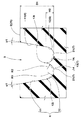
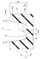
図3(a)は、タイヤ軸方向の一方側から見た主溝の断面斜視図である。図3(b)は、タイヤ軸方向の他方側から見た主溝の断面斜視図である。一対の側壁面14、14には、突起部13の頂点13t(図2に示す)から溝底部7に向かってのび、かつ、主溝3の長手方向に隔設される第1細溝19が設けられるのが望ましい。このように、第1細溝19は、突起部13に照射された光の一部を、第1細溝19内に取り込むことができる。従って、第1細溝19は、溝底部7を効果的に黒く目立たなく見せるのに役立つ。
Fig.3 (a) is a cross-sectional perspective view of the main groove seen from one side of the tire axial direction. FIG. 3B is a cross-sectional perspective view of the main groove viewed from the other side in the tire axial direction. The pair of side wall surfaces 14, 14 have first
しかも、第1細溝19は、突起部13の頂点13t(図2に示す)側に形成されているため、突起部13の一対の側壁面14、14において、比較的目立ちやすいタイヤ半径方向の外側部分に照射された光を、効果的に取り込むことができる。
Moreover, since the first
本実施形態では、各側壁面14、14に設けられる第1細溝19、19が、主溝3の幅方向で隣り合って形成されている。これにより、一対の側壁面14、14は、主溝3の幅方向において、トレッド部2の踏面2Sと溝底部7とのコントラストに差異が生じるのを防ぐことができる。なお、各側壁面14、14に設けられる第1細溝19、19は、主溝3の長手方向で交互に形成されてもよいのは言うまでもない。
In the present embodiment, the first
第1細溝19の側壁面14に沿った長さL4(図3(a)に示す)については、適宜設定することができる。なお、第1細溝19の長さL4が小さいと、突起部13に照射された光を十分に吸収することができないおそれがある。逆に、第1細溝19の長さL4が大きすぎても、第1細溝19において歪が集中し、突起部13にクラック等の損傷が発生しやすくなるおそれがある。このような観点より、第1細溝19の長さL4は、好ましくは、突起部13の隆起高さH2(図2に示す)の40%以上、さらに好ましくは45%以上であり、また、好ましくは60%以下、さらに好ましくは55%以下である。
The length L4 (shown in FIG. 3A) along the
同様の観点より、第1細溝19の溝幅(図示省略)は、0.3mm〜1.2mmが望ましい。また、第1細溝19の溝深さ(図示省略)は、0.3mm〜0.7mmが望ましい。さらに、主溝3の長手方向において、第1細溝19のピッチP4は、0.1mm〜0.3mmが望ましい。
From the same viewpoint, the groove width (not shown) of the first
さらに、一対の円弧面12、12には、円弧面12のタイヤ半径方向の外端12t(図2に示す)から、溝底部7に向かってのび、かつ、主溝3の長手方向に隔設される第2細溝20が設けられるのが望ましい。このような第2細溝20は、溝壁部6に照射された光の一部を、第2細溝20内に取り込むことができる。従って、第2細溝20は、溝底部7を黒く目立たなく見せるのに役立つ。しかも、第2細溝20は、円弧面12の外端12t側に形成されているため、溝壁部6の基面11に比べて目立ちやすい円弧面12において、溝壁部6に照射された光を、効果的に取り込むことができる。
Further, the pair of
本実施形態では、各円弧面12、12に設けられる第2細溝20、20が、主溝3の幅方向で隣り合って形成されている。これにより、一対の溝壁部6、6は、主溝3の幅方向において、トレッド部2の踏面2Sと溝底部7とのコントラストに差異が生じるのを防ぐことができる。なお、各円弧面12、12に設けられる第2細溝20、20は、主溝3の長手方向で交互に形成されてもよいのは言うまでもない。
In the present embodiment, the second
第2細溝20の円弧面12に沿った長さL6(図3(b)に示す)については、適宜設定することができる。なお、第2細溝20の長さL6は、第1細溝19と同様の観点より、好ましくは、突起部13の隆起高さH2の40%以上、さらに好ましくは45%以上であり、また、好ましくは60%以下、さらに好ましくは55%以下である。
The length L6 (shown in FIG. 3B) along the
第2細溝20の溝幅(図示省略)、第2細溝20の溝深さ(図示省略)、及び、主溝3の長手方向での第2細溝20のピッチP6は、第1細溝19の溝幅(図示省略)、第1細溝19の溝深さ(図示省略)、及び、第1細溝19のピッチP4(図3(a)に示す)と同一範囲に設定されるのが望ましい。
The groove width (not shown) of the second
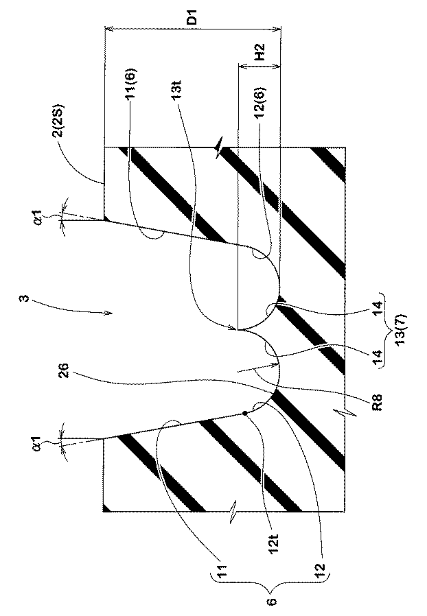
図2に示されるように、本実施形態の溝底部7は、一対の溝壁部6、6と突起部13との間を、トレッド部2の踏面2Sと平行にのびる一対の溝底面21、21が設けられている。
As shown in FIG. 2, the
図4は、図2の部分拡大図である。各溝底面21の長さL7は、適宜設定することができる。なお、長さL7が大きいと、溝底面21に照射された光の大部分を、主溝3の外側へ直接反射させてしまい、トレッド部2の踏面2Sと溝底部7とのコントラストを十分に高くすることができなくなるおそれがある。このため、溝底面21の長さL7は、溝底面21、溝壁部6及び側壁面14が連続する溝輪郭線の長さL8の13%以下、さらに好ましくは10%以下に設定されるのが望ましい。
FIG. 4 is a partially enlarged view of FIG. The length L7 of each
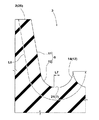
本実施形態では、溝底部7に溝底面21が形成されるものが例示されたが、これに限定されるわけではない。図5は、本発明の他の実施形態の主溝3を示す断面図である。図5に示されるように、溝底部7には、溝底面21(図2に示す)を形成することなく、一対の側壁面14、14が、主溝3の幅方向外側に配置される一対の溝壁部6、6の円弧面12、12と連続して形成されてもよい。これにより、一対の側壁面14、14及び一対の円弧面12、12は、溝壁部6及び溝底部7に照射された光を、満遍なく乱反射させることができるため、トレッド部2の踏面2Sと溝底部7とのコントラストを、効果的に高くすることができる。
In the present embodiment, an example in which the
側壁面14及び円弧面12が連続する溝輪郭線は、タイヤ半径方向内側に凸となる一つの円弧26から形成されるのが望ましい。これにより、側壁面14及び円弧面12は、主溝3から照射された光を、均一に乱反射させることができるため、トレッド部2の踏面2Sと溝底部7とのコントラストを、効果的に高くすることができる。円弧26の曲率半径R8は、各側壁面14、14の曲率半径R2(図2に示す)と同一に設定されるのが望ましい。
The groove contour line in which the
本実施形態では、図1に示したセンター主溝3A及び一対のショルダー主溝3B、3Bの双方に、突起部13(図2に示す)が形成されるものが例示されたが、これに限定されるわけではない。例えば、突起部13は、複数本の主溝3のうち、最大溝幅W1が最も大きい主溝3(例えば、一対のショルダー主溝3B、3B)のみに形成されてもよい。これにより、タイヤ1は、製造コストを抑えつつ、タイヤが早期に摩耗するのではないか等の不安を、ユーザに与えるのを防ぐことができる。
In the present embodiment, the center
本実施形態の突起部13は、ストレート溝として形成された主溝3に設けられるものが例示されたが、これに限定されるわけではない。突起部13は、例えば、緩やかな波状やジグザグ状にのびる主溝(図示省略)に設けられてもよい。
Although the
以上、本発明の特に好ましい実施形態について詳述したが、本発明は図示の実施形態に限定されることなく、種々の態様に変形して実施しうる。 As mentioned above, although especially preferable embodiment of this invention was explained in full detail, this invention is not limited to embodiment of illustration, It can deform | transform and implement in a various aspect.
図1に示す基本構造をなし、図2及び表1に示す主溝及び突起部を有するタイヤが製造され、それらの性能が評価された。さらに、図1に示す基本構造をなし、図5及び表1に示す主溝及び突起部を有するタイヤが製造され、それらの性能が評価された。 Tires having the basic structure shown in FIG. 1 and having the main grooves and protrusions shown in FIG. 2 and Table 1 were manufactured, and their performance was evaluated. Furthermore, tires having the basic structure shown in FIG. 1 and having the main grooves and protrusions shown in FIG. 5 and Table 1 were manufactured, and their performance was evaluated.
また、比較のために、主溝の溝深さが8.7mmかつ突起部を有さないタイヤ(比較例1)や、主溝の溝深さが実施例と同一かつ突起部を有さないタイヤ(比較例2)についても製造され、それらの性能が同様に評価された。なお、共通仕様は以下の通りである。
タイヤサイズ:195/65R15
リムサイズ:15×6.0JJ
突起部が設けられる主溝:センター主溝、ショルダー主溝
側壁面の曲率半径R2:1.0mm
円弧面の曲率半径R3:1.0mm
基面の角度α1:10度
第1細溝:
溝幅:0.8mm
溝深さ:0.5mm
ピッチP4:0.2mm
第2細溝:
溝幅:0.8mm
溝深さ:0.5mm
ピッチP6:0.2mm
溝輪郭線の長さL8:8.0mm
図5の円弧の曲率半径R8:1.0mm
テスト方法は、次のとおりである。
For comparison, the tire has a groove depth of 8.7 mm and no protrusion (Comparative Example 1), and the groove depth of the main groove is the same as that of the embodiment and does not have a protrusion. Tires (Comparative Example 2) were also produced and their performance was similarly evaluated. The common specifications are as follows.
Tire size: 195 / 65R15
Rim size: 15 × 6.0JJ
Main groove provided with protrusions: center main groove, shoulder main groove radius of curvature R2 of side wall surface: 1.0 mm
Arc surface radius of curvature R3: 1.0mm
Base surface angle α1: 10 degrees First fine groove:
Groove width: 0.8mm
Groove depth: 0.5mm
Pitch P4: 0.2mm
Second narrow groove:
Groove width: 0.8mm
Groove depth: 0.5mm
Pitch P6: 0.2mm
Groove contour length L8: 8.0 mm
Curvature radius R8 of FIG. 5: 1.0 mm
The test method is as follows.
<タイヤ質量>
リム組み前の各供試タイヤ1本当たりの質量が測定された。結果は、タイヤ質量の逆数を、比較例1を3.0とする5点法で評価された。数値が大きいほど、タイヤ質量が小さいことを示している。
<Tire mass>
The mass per each test tire before assembling the rim was measured. The results were evaluated by a 5-point method in which the reciprocal of the tire mass was set to 3.0 as Comparative Example 1. It shows that tire mass is so small that a numerical value is large.
<転がり抵抗性能>
下記の条件に基づいて、各供試タイヤを転がり抵抗試験機のドラム上で走行させて、転がり抵抗が測定された。結果は、転がり抵抗の逆数を、比較例1を3.0とする5点法で評価された。数値が大きいほど、転がり抵抗が小さく良好である。
内圧:210kPa
荷重:4.82kN
速度:80km/h
ドラムの直径:1.7m
<Rolling resistance performance>
Based on the following conditions, each test tire was run on a drum of a rolling resistance tester, and the rolling resistance was measured. The results were evaluated by a 5-point method in which the reciprocal of the rolling resistance was set to 3.0 as Comparative Example 1. The larger the value, the smaller the rolling resistance and the better.
Internal pressure: 210 kPa
Load: 4.82kN
Speed: 80km / h
Drum diameter: 1.7m
<タイヤの外観性>
各供試タイヤが、上記リムにリム組みされ、内圧(230kPa)が充填された。そして、各供試タイヤの主溝に太陽光が照射され、トレッド部の踏面と、主溝内とのコントラストが目視にて確認された。結果は、比較例1を3.0とする5点法で評価された。数値が大きいほど、主溝の溝底が目立ちにくく、良好である。
<Appearance of tires>
Each test tire was assembled on the rim and filled with internal pressure (230 kPa). And the sunlight was irradiated to the main groove of each test tire, and the contrast between the tread surface and the inside of the main groove was visually confirmed. The results were evaluated by a 5-point method with Comparative Example 1 as 3.0. As the numerical value is larger, the groove bottom of the main groove is less noticeable and better.
<タイヤの耐久性能>
下記の条件に基づいて、各供試タイヤをドラム試験機上で走行させて、タイヤが破壊するまでの走行距離が測定された。結果は、走行距離の逆数を、比較例1の値を3.0とする指数で表示した。数値が大きいほど良好である。
内圧:250kPa
荷重:8.15kN
速度:100km/h
ドラムの直径:1.7m
テストの結果を表1に示す。
<Tire durability>
Based on the following conditions, each test tire was run on a drum testing machine, and the running distance until the tire broke was measured. The results were expressed as the reciprocal of the travel distance as an index with the value of Comparative Example 1 as 3.0. The larger the value, the better.
Internal pressure: 250 kPa
Load: 8.15kN
Speed: 100km / h
Drum diameter: 1.7m
The test results are shown in Table 1.
テストの結果、実施例のタイヤは、トレッド部のゴムボリュームを削減(タイヤ質量を低減)して、転がり抵抗性を向上させつつ、タイヤの外観を向上しうる(タイヤが早期に摩耗するのではないか等の不安を、ユーザに与えるのを防ぎうる)ことを確認することができた。 As a result of the test, the tire of the example can improve the appearance of the tire while reducing the rubber volume of the tread portion (reducing the tire mass) and improving the rolling resistance (the tire is worn early). It can be confirmed that the user can be prevented from giving anxiety such as whether there is any).
1 空気入りタイヤ
2 トレッド部
3 主溝
6 溝壁部
7 溝底部
13 突起部
DESCRIPTION OF SYMBOLS 1
Claims (12)
前記主溝の最大溝深さは、6mm以上7mm以下であり、
前記主溝は、その長手方向と直角な溝断面において、
前記トレッド部の踏面からタイヤ半径方向内側にのびる一対の溝壁部と、前記一対の溝壁部の間の溝底部とを含み、
前記溝底部は、タイヤ半径方向外側に隆起する突起部を含むことを特徴とする空気入りタイヤ。 A pneumatic tire having at least one main groove extending in a tire circumferential direction in a tread portion,
The maximum groove depth of the main groove is 6 mm or more and 7 mm or less,
In the groove cross section perpendicular to the longitudinal direction of the main groove,
A pair of groove wall portions extending inward in the tire radial direction from a tread surface of the tread portion, and a groove bottom portion between the pair of groove wall portions,
The pneumatic tire according to claim 1, wherein the groove bottom portion includes a protruding portion that protrudes outward in the tire radial direction.
前記一対の側壁面は、タイヤ半径方向内側に向かって凸となる円弧で形成されている請求項1乃至2のいずれかに記載の空気入りタイヤ。 In the groove cross section, the protrusion includes a pair of side wall surfaces extending outward in the tire radial direction,
The pneumatic tire according to any one of claims 1 to 2, wherein the pair of side wall surfaces are formed by arcs that are convex toward the inside in the tire radial direction.
前記溝底面の長さは、前記溝底面、前記溝壁部及び前記側壁面が連続する溝輪郭線の長さの13%以下である請求項3乃至10のいずれかに記載の空気入りタイヤ。 In the groove cross section, the groove bottom portion has a groove bottom surface extending parallel to the tread surface of the tread portion between the pair of groove wall portions and the projection portion,
The pneumatic tire according to any one of claims 3 to 10, wherein a length of the groove bottom surface is 13% or less of a length of a groove contour line in which the groove bottom surface, the groove wall portion, and the side wall surface are continuous.
前記側壁面及び前記円弧面が連続する溝輪郭線は、タイヤ半径方向内側に凸となる一つの円弧から形成される請求項8乃至10のいずれかに記載の空気入りタイヤ。 In the groove cross section, the pair of side wall surfaces are formed continuously with the arc surfaces of the pair of groove wall portions disposed on the outer side in the width direction of the main groove,
The pneumatic tire according to any one of claims 8 to 10, wherein a groove contour line in which the side wall surface and the arc surface are continuous is formed from a single arc that is convex inward in the tire radial direction.
Priority Applications (1)
| Application Number | Priority Date | Filing Date | Title |
|---|---|---|---|
| JP2013267544A JP2015123772A (en) | 2013-12-25 | 2013-12-25 | Pneumatic tire |
Applications Claiming Priority (1)
| Application Number | Priority Date | Filing Date | Title |
|---|---|---|---|
| JP2013267544A JP2015123772A (en) | 2013-12-25 | 2013-12-25 | Pneumatic tire |
Publications (1)
| Publication Number | Publication Date |
|---|---|
| JP2015123772A true JP2015123772A (en) | 2015-07-06 |
Family
ID=53534825
Family Applications (1)
| Application Number | Title | Priority Date | Filing Date |
|---|---|---|---|
| JP2013267544A Pending JP2015123772A (en) | 2013-12-25 | 2013-12-25 | Pneumatic tire |
Country Status (1)
| Country | Link |
|---|---|
| JP (1) | JP2015123772A (en) |
Cited By (2)
| Publication number | Priority date | Publication date | Assignee | Title |
|---|---|---|---|---|
| CN111483274A (en) * | 2019-01-25 | 2020-08-04 | 住友橡胶工业株式会社 | Tyre for vehicle wheels |
| CN114953856A (en) * | 2021-02-22 | 2022-08-30 | 住友橡胶工业株式会社 | Tyre |
-
2013
- 2013-12-25 JP JP2013267544A patent/JP2015123772A/en active Pending
Cited By (2)
| Publication number | Priority date | Publication date | Assignee | Title |
|---|---|---|---|---|
| CN111483274A (en) * | 2019-01-25 | 2020-08-04 | 住友橡胶工业株式会社 | Tyre for vehicle wheels |
| CN114953856A (en) * | 2021-02-22 | 2022-08-30 | 住友橡胶工业株式会社 | Tyre |
Similar Documents
| Publication | Publication Date | Title |
|---|---|---|
| JP5476410B2 (en) | Pneumatic tire | |
| CN102811871B (en) | Pneumatic tire | |
| US9302550B2 (en) | Pneumatic tire | |
| JP6006745B2 (en) | Pneumatic tire | |
| JP6599218B2 (en) | Pneumatic tire | |
| JP5779164B2 (en) | Pneumatic tire | |
| JP5756490B2 (en) | Pneumatic tire | |
| JP6844377B2 (en) | tire | |
| JP2013248927A (en) | Pneumatic tire | |
| JP7110596B2 (en) | tire | |
| JP2009262829A (en) | Pneumatic tire | |
| JP7306163B2 (en) | tire | |
| JP2018052152A (en) | tire | |
| JP5351928B2 (en) | Pneumatic tire | |
| JP2014240171A (en) | Pneumatic bias tire and its manufacturing method | |
| JP2017128269A (en) | Pneumatic tire | |
| US10343465B2 (en) | Pneumatic tire | |
| JP7189800B2 (en) | pneumatic tire | |
| JP2015123772A (en) | Pneumatic tire | |
| JP2011245996A (en) | Pneumatic tire | |
| JP5947532B2 (en) | Pneumatic tire | |
| JP7276574B2 (en) | tire | |
| JP5990394B2 (en) | Run flat tire | |
| JP2009208595A (en) | Pneumatic radial tire | |
| JP6196555B2 (en) | Pneumatic tire |