JP2015123765A - Motor cycle - Google Patents
Motor cycle Download PDFInfo
- Publication number
- JP2015123765A JP2015123765A JP2013267464A JP2013267464A JP2015123765A JP 2015123765 A JP2015123765 A JP 2015123765A JP 2013267464 A JP2013267464 A JP 2013267464A JP 2013267464 A JP2013267464 A JP 2013267464A JP 2015123765 A JP2015123765 A JP 2015123765A
- Authority
- JP
- Japan
- Prior art keywords
- vertical portion
- width direction
- vehicle
- side cover
- vehicle width
- Prior art date
- Legal status (The legal status is an assumption and is not a legal conclusion. Google has not performed a legal analysis and makes no representation as to the accuracy of the status listed.)
- Pending
Links
Images


Classifications
-
- B—PERFORMING OPERATIONS; TRANSPORTING
- B62—LAND VEHICLES FOR TRAVELLING OTHERWISE THAN ON RAILS
- B62J—CYCLE SADDLES OR SEATS; AUXILIARY DEVICES OR ACCESSORIES SPECIALLY ADAPTED TO CYCLES AND NOT OTHERWISE PROVIDED FOR, e.g. ARTICLE CARRIERS OR CYCLE PROTECTORS
- B62J17/00—Weather guards for riders; Fairings or stream-lining parts not otherwise provided for
- B62J17/02—Weather guards for riders; Fairings or stream-lining parts not otherwise provided for shielding only the rider's front
- B62J17/06—Leg guards
-
- B—PERFORMING OPERATIONS; TRANSPORTING
- B62—LAND VEHICLES FOR TRAVELLING OTHERWISE THAN ON RAILS
- B62J—CYCLE SADDLES OR SEATS; AUXILIARY DEVICES OR ACCESSORIES SPECIALLY ADAPTED TO CYCLES AND NOT OTHERWISE PROVIDED FOR, e.g. ARTICLE CARRIERS OR CYCLE PROTECTORS
- B62J17/00—Weather guards for riders; Fairings or stream-lining parts not otherwise provided for
- B62J17/10—Ventilation or air guiding devices forming part of fairings
-
- B—PERFORMING OPERATIONS; TRANSPORTING
- B62—LAND VEHICLES FOR TRAVELLING OTHERWISE THAN ON RAILS
- B62J—CYCLE SADDLES OR SEATS; AUXILIARY DEVICES OR ACCESSORIES SPECIALLY ADAPTED TO CYCLES AND NOT OTHERWISE PROVIDED FOR, e.g. ARTICLE CARRIERS OR CYCLE PROTECTORS
- B62J6/00—Arrangement of optical signalling or lighting devices on cycles; Mounting or supporting thereof; Circuits therefor
- B62J6/05—Direction indicators
- B62J6/055—Electrical means, e.g. lamps
-
- B—PERFORMING OPERATIONS; TRANSPORTING
- B62—LAND VEHICLES FOR TRAVELLING OTHERWISE THAN ON RAILS
- B62K—CYCLES; CYCLE FRAMES; CYCLE STEERING DEVICES; RIDER-OPERATED TERMINAL CONTROLS SPECIALLY ADAPTED FOR CYCLES; CYCLE AXLE SUSPENSIONS; CYCLE SIDE-CARS, FORECARS, OR THE LIKE
- B62K11/00—Motorcycles, engine-assisted cycles or motor scooters with one or two wheels
- B62K11/02—Frames
- B62K11/04—Frames characterised by the engine being between front and rear wheels
Abstract
Description
本発明は、自動二輪車に関する。 The present invention relates to a motorcycle.
従来から、フロントカバーとサイドカバーとを備えた自動二輪車が知られている。フロントカバーおよびサイドカバーを備えることにより、自動二輪車の空気抵抗を低減することができる。また、自動二輪車の走行に伴って前方から後方に向かって流れる風(以下、走行風という。)が乗員に強く当たることを防止することができる。フロントカバーはヘッドパイプの前方に位置し、サイドカバーはヘッドパイプの側方に位置する。特許文献1には、第1のサイドカバーと、第1のサイドカバーの車幅方向の外方に配置された第2のサイドカバーとを有する自動二輪車が記載されている。 Conventionally, a motorcycle including a front cover and a side cover is known. By providing the front cover and the side cover, the air resistance of the motorcycle can be reduced. In addition, it is possible to prevent a wind that flows from the front to the rear (hereinafter referred to as traveling wind) from hitting the occupant strongly as the motorcycle travels. The front cover is located in front of the head pipe, and the side cover is located on the side of the head pipe. Patent Document 1 describes a motorcycle having a first side cover and a second side cover arranged on the outer side of the first side cover in the vehicle width direction.
特許文献1に記載された自動二輪車では、第1のサイドカバーと第2のサイドカバーとの間に、走行風の通路として車両前後方向に延びる孔が形成されている。走行風は、孔を通過して後方に導かれる。孔を通過した走行風は、第2のサイドカバーの外方を流れる走行風と合流する。 In the motorcycle described in Patent Document 1, a hole extending in the vehicle front-rear direction is formed as a passage of traveling wind between the first side cover and the second side cover. The traveling wind is guided rearward through the hole. The traveling wind that has passed through the hole merges with the traveling wind that flows outside the second side cover.
ところで、特許文献1に記載されている自動二輪車では、第1のサイドカバーおよび第2のサイドカバーの下方に、導風部材が配置されている。乗員が自動二輪車に乗車する際、乗員の脚は導風部材の後方に位置付けられる。上記自動二輪車では、導風部材に車幅方向に延びるフラッシャランプが取り付けられている。走行風は、フラッシャランプの前方からフラッシャランプに当たるため、フラッシャランプの後方では走行風の乱れが発生する。乱れた走行風は乗員の脚に直接当たるため、走行風に乱れがない場合と比較して、乗車時の快適性が低下してしまう。 By the way, in the motorcycle described in Patent Document 1, an air guide member is arranged below the first side cover and the second side cover. When the occupant gets on the motorcycle, the occupant's legs are positioned behind the air guide member. In the motorcycle, a flasher lamp extending in the vehicle width direction is attached to the air guide member. Since the traveling wind hits the flasher lamp from the front of the flasher lamp, the traveling wind is disturbed behind the flasher lamp. Since the turbulent traveling wind directly hits the occupant's legs, the comfort during riding is reduced as compared with the case where the traveling wind is not disturbed.
一方、フラッシャランプを第2のサイドカバーに取り付けた場合、乱れた走行風は乗員の脚に当たりにくくなる。しかし、第2のサイドカバーは導風部材より車幅方向の外方に位置する。そのため、フラッシャランプを第2のサイドカバーに取り付けた場合、自動二輪車の車幅方向の大きさが大きくなってしまう。 On the other hand, when the flasher lamp is attached to the second side cover, the disturbed traveling wind is less likely to hit the occupant's leg. However, the second side cover is located outward in the vehicle width direction from the air guide member. Therefore, when the flasher lamp is attached to the second side cover, the size of the motorcycle in the vehicle width direction is increased.
本発明はかかる点に鑑みてなされたものであり、その目的は、車幅方向の大型化の抑制と乗車時の快適性の向上とを両立させることができる自動二輪車を提供することである。 The present invention has been made in view of the above points, and an object of the present invention is to provide a motorcycle that can achieve both suppression of enlargement in the vehicle width direction and improvement of comfort during riding.
本発明に係る自動二輪車は、ヘッドパイプと、前記ヘッドパイプから後方に延びる車体フレームと、前記ヘッドパイプの後方に位置し、乗員が着座するシートと、前記ヘッドパイプの車幅方向の外方に配置された第1のサイドカバーと、車両側面視で前記第1のサイドカバーと重なりかつ下方に延びる縦部を有し、前記第1のサイドカバーの車幅方向の外方に配置された第2のサイドカバーと、前記第1のサイドカバーのうち車両側面視で前記第1のサイドカバーと前記第2のサイドカバーとが重ならない位置であり、かつ前記縦部より前方の位置に取り付けられ、車両正面視で少なくとも一部が前記第2のサイドカバーの車幅方向の外方に位置するフラッシャランプと、前記シートより下方かつ前記第2のサイドカバーの後方に位置し、乗員の足を載せるステップと、を備え、前記第1のサイドカバーと前記縦部との間には、走行風が通過する走行風通路が形成され、前記フラッシャランプは、前記走行風通路の前方に位置する。 The motorcycle according to the present invention includes a head pipe, a vehicle body frame extending rearward from the head pipe, a seat positioned behind the head pipe and seated by an occupant, and outward of the head pipe in the vehicle width direction. A first side cover that is disposed, and a vertical portion that overlaps the first side cover and extends downward in a side view of the vehicle, and is disposed outside the first side cover in the vehicle width direction. 2 of the first side cover and the first side cover, the first side cover and the second side cover are not overlapped with each other when viewed from the side of the vehicle, and are attached to the front of the vertical portion. A flasher lamp positioned at least partially outside the second side cover in the vehicle width direction when viewed from the front of the vehicle, and positioned below the seat and behind the second side cover, A running air passage through which running wind passes is formed between the first side cover and the vertical portion, and the flasher lamp is disposed in front of the running wind passage. To position.
本発明に係る自動二輪車では、フラッシャランプは、車両側面視で、第1のサイドカバーのうち第1のサイドカバーと第2のサイドカバーとが重ならない位置であり、かつ縦部より前方の位置に取り付けられている。そして、フラッシャランプの少なくとも一部は、車両正面視で、第2のサイドカバーの車幅方向の外方に位置する。このため、走行風がフラッシャランプに当たることによって、フラッシャランプの後方では走行風に乱れが発生する。本発明では、フラッシャランプは、第1のサイドカバーと縦部との間に形成された走行風通路の前方に位置する。このため、フラッシャランプの後方で発生した乱れた走行風は、走行風通路へと導かれる。乱れた走行風は、走行風通路内を通過する際に整流される。これにより、乗員の脚には、乱れた走行風ではなく整流された走行風が当たることになる。この結果、乗車時の快適性が向上される。また、フラッシャランプは、第2のサイドカバーより車幅方向の内方に配置された第1のサイドカバーに取り付けられている。このため、フラッシャランプを第2のサイドカバーに取り付けた場合と比較して、自動二輪車の車幅方向の大型化を抑制することができる。 In the motorcycle according to the present invention, the flasher lamp is a position in which the first side cover and the second side cover of the first side cover do not overlap with each other in a side view of the vehicle and a position in front of the vertical portion. Is attached. And at least one part of a flasher lamp is located in the vehicle width direction outer side of a 2nd side cover by vehicle front view. For this reason, when the traveling wind hits the flasher lamp, the traveling wind is disturbed behind the flasher lamp. In the present invention, the flasher lamp is located in front of the traveling air passage formed between the first side cover and the vertical portion. For this reason, the turbulent traveling wind generated behind the flasher lamp is guided to the traveling wind passage. The turbulent traveling wind is rectified when passing through the traveling wind passage. As a result, the rectified traveling wind hits the occupant's legs instead of the turbulent traveling wind. As a result, comfort when riding is improved. The flasher lamp is attached to a first side cover that is disposed inward in the vehicle width direction from the second side cover. For this reason, compared with the case where a flasher lamp is attached to a 2nd side cover, the enlargement of the motorcycle width direction can be suppressed.
本発明の一態様によれば、前記ヘッドパイプの後方に位置し、前記車体フレームに支持されたエンジンを備え、前記エンジンは、前記縦部より車幅方向の内方に位置し、前記縦部を横切る水平断面において、前記縦部の後端部は、車幅方向の内方に向けて延びる。 According to an aspect of the present invention, the engine includes an engine positioned behind the head pipe and supported by the vehicle body frame, the engine positioned inward in the vehicle width direction from the vertical portion, and the vertical portion The rear end of the vertical portion extends inward in the vehicle width direction.
上記態様によれば、走行風通路内を通過する際に整流された走行風は、縦部の後端部に当たる。縦部の後端部は、車両平面視で車幅方向の内方に向けて延びているため、整流された走行風は、車幅方向の内方に導かれる。これにより、乗員の脚に当たる走行風を低減することができ、乗車時の快適性が向上される。また、整流された走行風は、縦部より車幅方向の内方に位置するエンジンに導かれる。このため、エンジンを冷却することができる。 According to the above aspect, the traveling wind rectified when passing through the traveling wind passage hits the rear end of the vertical portion. Since the rear end portion of the vertical portion extends inward in the vehicle width direction in a plan view of the vehicle, the rectified traveling wind is guided inward in the vehicle width direction. As a result, traveling wind hitting the occupant's legs can be reduced, and comfort when riding is improved. Further, the rectified traveling wind is guided to the engine located inward in the vehicle width direction from the vertical portion. For this reason, the engine can be cooled.
本発明の一態様によれば、前記縦部の後端は、前記縦部の前端より車幅方向の内方に位置する。 According to an aspect of the present invention, the rear end of the vertical portion is located inward in the vehicle width direction from the front end of the vertical portion.
上記態様によれば、走行風通路により多くの走行風を導くことができる。この結果、エンジンにより多くの走行風を導くことができ、エンジンの冷却性能が向上する。 According to the above aspect, more traveling wind can be guided to the traveling wind passage. As a result, more running wind can be guided to the engine, and the cooling performance of the engine is improved.
本発明の一態様によれば、前記エンジンは、クランクケースと、前記クランクケースから上方に延びるシリンダボディと、前記シリンダボディに結合されたシリンダヘッドと、を有し、前記縦部の下端は、前記シリンダヘッドの下端よりも下方に位置する。 According to an aspect of the present invention, the engine includes a crankcase, a cylinder body extending upward from the crankcase, and a cylinder head coupled to the cylinder body, and a lower end of the vertical portion is It is located below the lower end of the cylinder head.
上記態様によれば、走行風通路の上下方向の長さが比較的長くなる。このため、走行風通路を通過する走行風が多くなる。これにより、より多くの走行風をエンジンに導くことができ、エンジンの冷却性能が向上する。 According to the said aspect, the length of the up-down direction of a driving | running | working wind path becomes comparatively long. For this reason, the traveling wind passing through the traveling wind passage increases. As a result, more traveling wind can be guided to the engine, and the cooling performance of the engine is improved.
本発明の一態様によれば、前記縦部は、車両側面視で、前記車体フレームのうち前記エンジンの前方に位置する部分と重なる。 According to an aspect of the present invention, the vertical portion overlaps a portion of the body frame located in front of the engine in a side view of the vehicle.
上記態様によれば、走行風通路の車両前後方向の長さが比較的長くなる。このため、走行風通路を通過する走行風はより確実に整流される。整流された走行風は、エンジンに導かれ、エンジンを冷却することができる。 According to the above aspect, the length of the traveling wind passage in the longitudinal direction of the vehicle is relatively long. For this reason, the traveling wind passing through the traveling wind passage is more reliably rectified. The rectified traveling wind is guided to the engine and can cool the engine.
本発明の一態様によれば、前記第1のサイドカバーは、車両側面視で前記縦部と重なる他の縦部を有し、前記縦部は、前記他の縦部の後端よりも後方に位置する後端を備える。 According to an aspect of the present invention, the first side cover has another vertical portion that overlaps the vertical portion in a side view of the vehicle, and the vertical portion is behind the rear end of the other vertical portion. And a rear end located at the end.
上記態様によれば、走行風通路内を通過し、第2のサイドカバーの縦部の後端部に当たった走行風は、車幅方向の内方により確実に導かれる。これにより、乗員の脚に当たる走行風を低減することができる。また、走行風をより確実にエンジンに導くことができるため、エンジンの冷却性能が向上する。 According to the above aspect, the traveling wind that passes through the traveling wind passage and hits the rear end of the vertical portion of the second side cover is reliably guided inward in the vehicle width direction. Thereby, the driving | running | working wind which hits a passenger | crew's leg can be reduced. Further, since the traveling wind can be more reliably guided to the engine, the cooling performance of the engine is improved.
本発明の一態様によれば、前記他の縦部には、車幅方向の外方に向けて突出し、車両前後方向に延びる凸部が形成され、前記凸部の少なくとも一部は、車両側面視で前記縦部と重なる。 According to an aspect of the present invention, the other vertical portion is formed with a convex portion that protrudes outward in the vehicle width direction and extends in the vehicle front-rear direction, and at least a portion of the convex portion is a vehicle side surface. Visually overlaps the vertical part.
上記態様によれば、フラッシャランプの後方で発生する乱れた走行風は、走行風通路内に位置する凸部によって整流される。これにより、乗員の脚には、整流された走行風が当たることになり、乗車時の快適性が向上する。 According to the above aspect, the turbulent traveling wind generated behind the flasher lamp is rectified by the convex portion located in the traveling wind passage. As a result, the rectified traveling wind hits the occupant's leg, and comfort during riding is improved.
本発明の一態様によれば、前記縦部の後端は、前記凸部のうち最も車幅方向の外方に位置する外端より車幅方向の内方に位置する。 According to an aspect of the present invention, the rear end of the vertical portion is located inward in the vehicle width direction from the outer end of the convex portion that is located most outward in the vehicle width direction.
上記態様によれば、凸部によって整流された走行風は車幅方向の内方に導かれる。このため、乗員の脚に当たる走行風を低減することができる。乗車時の快適性が向上される。 According to the above aspect, the traveling wind rectified by the convex portion is guided inward in the vehicle width direction. For this reason, the traveling wind which hits a passenger | crew's leg can be reduced. Comfort when riding is improved.
本発明の一態様によれば、前記ステップの車幅方向の内方に配置された車体カバーを備え、前記縦部と、前記車体カバーとを横切る水平断面において、前記縦部は、前記車体カバーより車幅方向の外方に位置する。 According to one aspect of the present invention, the vehicle body cover is disposed inward in the vehicle width direction of the step, and in the horizontal section across the vertical portion and the vehicle body cover, the vertical portion is the vehicle body cover. It is located more outward in the vehicle width direction.
上記態様によれば、車体カバーは、第2のサイドカバーの縦部より車幅方向の内方に位置する。このため、縦部より車幅方向の外方を通過する走行風は、乗員の脚に当たりにくくなる。 According to the above aspect, the vehicle body cover is positioned inward in the vehicle width direction from the vertical portion of the second side cover. For this reason, the traveling wind that passes outward in the vehicle width direction from the vertical portion is less likely to hit the occupant's legs.
本発明の一態様によれば、前記他の縦部と、前記車体カバーとを横切る水平断面において、前記他の縦部の少なくとも一部は、前記車体カバーのうち最も車幅方向の外方に位置する外端より車幅方向の内方に位置する。 According to an aspect of the present invention, in a horizontal cross section that crosses the other vertical portion and the vehicle body cover, at least a part of the other vertical portion is most outward in the vehicle width direction of the vehicle body cover. It is located inward in the vehicle width direction from the outer end.
上記態様によれば、第1のサイドカバーの他の縦部の少なくとも一部は、車体カバーのうち最も車幅方向の外方に位置する外端より車幅方向の内方に位置する。このため、走行風通路を通過する走行風は、車幅方向の内方に導かれる。この結果、走行風は、乗員の脚に当たりにくくなる。 According to the above aspect, at least a part of the other vertical portion of the first side cover is located inward in the vehicle width direction from the outer end of the body cover that is located most outward in the vehicle width direction. For this reason, the traveling wind passing through the traveling wind passage is guided inward in the vehicle width direction. As a result, the traveling wind is less likely to hit the passenger's leg.
本発明の一態様によれば、前記縦部を横切る水平断面において、前記縦部の前端部は、前方に行くほど車幅方向の内方に向かうように延びる。 According to an aspect of the present invention, in a horizontal section across the vertical portion, the front end portion of the vertical portion extends inward in the vehicle width direction as it goes forward.
上記態様によれば、第2のサイドカバーの縦部の前方から縦部に向かって流れる走行風は、縦部の前端部に当たる。縦部の前端部は、前方に行くほど車幅方向の内方に向かうように延びている。このため、縦部の前端部に当たった走行風は、車幅方向の内方、即ち第1のサイドカバーの方ではなく、縦部の外方、即ち第1のサイドカバーとは車幅方向で反対の方へと流れる。これにより、乗員の脚に当たる走行風を低減することができる。 According to the said aspect, the driving | running | working wind which flows toward the vertical part from the front of the vertical part of a 2nd side cover hits the front-end part of a vertical part. The front end portion of the vertical portion extends inward in the vehicle width direction as it goes forward. For this reason, the traveling wind hitting the front end of the vertical portion is not inward in the vehicle width direction, that is, in the first side cover, but in the vehicle width direction outside of the vertical portion, that is, with the first side cover. It flows in the opposite direction. Thereby, the driving | running | working wind which hits a passenger | crew's leg can be reduced.
本発明の一態様によれば、前記フラッシャランプは、ランプ部と、前記ランプ部と前記第1のサイドカバーとの間に位置し、前記ランプ部と前記第1のサイドカバーとを連結する連結部とを有し、前記連結部は、屈曲可能であり、前記連結部が屈曲したとき、前記ランプ部は、車両正面視で、前記第2のサイドカバーのうち最も車幅方向の外方に位置する外端より車幅方向の内方に位置する。 According to an aspect of the present invention, the flasher lamp is located between the lamp unit and the lamp unit and the first side cover, and connects the lamp unit and the first side cover. The connecting portion is bendable, and when the connecting portion is bent, the ramp portion is most outward in the vehicle width direction of the second side cover in a vehicle front view. It is located inward in the vehicle width direction from the outer end.
上記態様によれば、自動二輪車に対して側方からの力が加わったとき、連結部は屈曲する。ランプ部は、連結部の屈曲によって、第2のサイドカバーのうち最も車幅方向の外方に位置する外端より車幅方向の内方に位置することができる。このため、側方からの力は第2のサイドカバーに分散され、フラッシャランプに加わる力が低減される。これにより、ランプ部の破損を防止することができる。 According to the above aspect, the connecting portion bends when a lateral force is applied to the motorcycle. The ramp portion can be positioned inward in the vehicle width direction from the outer end of the second side cover that is positioned most outward in the vehicle width direction by bending of the connecting portion. For this reason, the force from the side is distributed to the second side cover, and the force applied to the flasher lamp is reduced. Thereby, damage to the lamp portion can be prevented.
以上のように、本発明によれば、車幅方向の大型化の抑制と乗車時の快適性の向上とを両立させることができる自動二輪車を提供することができる。 As described above, according to the present invention, it is possible to provide a motorcycle that can achieve both suppression of increase in size in the vehicle width direction and improvement in comfort during riding.
以下、本発明の実施形態について説明する。図1に示すように、本実施形態に係る自動二輪車1は、オンロード型の自動二輪車1である。なお、本発明に係る自動二輪車はオンロード型の自動二輪車1に限定される訳ではない。本発明に係る自動二輪車は、いわゆるモペット型、オフロード型、またはスクータ型等の他の型式の自動二輪車であってもよい。 Hereinafter, embodiments of the present invention will be described. As shown in FIG. 1, a motorcycle 1 according to this embodiment is an on-road motorcycle 1. Note that the motorcycle according to the present invention is not limited to the on-road motorcycle 1. The motorcycle according to the present invention may be a so-called moped, off-road, or other type of motorcycle such as a scooter.
以下の説明において、特に断らない限り、前、後、左、右、上、下は、それぞれ自動二輪車1のシート3に着座した乗員から見た前、後、左、右、上、下を意味するものとする。上、下は、それぞれ自動二輪車1が水平面上に停止しているときの鉛直方向の上、下を意味するものとする。図面に付した符号F、Re、L、R、Up,Dnは、それぞれ前、後、左、右、上、下を表す。
In the following description, unless otherwise specified, front, rear, left, right, upper, and lower mean front, rear, left, right, upper, and lower as viewed from the occupant seated on the
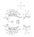
図1に示すように、自動二輪車1は、ヘッドパイプ5と、ヘッドパイプ5に固定された車体フレーム10とを備えている。車体フレーム10は、ヘッドパイプ5から後方に延びる。車体フレーム10は、ヘッドパイプ5から後方に延びるメインフレーム12と、ヘッドパイプ5から下方に延びる第1ダウンフレーム14と、メインフレーム12の後部から後方に延びるシートフレーム16と、メインフレーム12の後部から下方に延びる第2ダウンフレーム18と、第2ダウンフレーム18から後方に延び、第2ダウンフレーム18とシートフレーム16とを連結するバックステー20とを有している。メインフレーム12は、ヘッドパイプ5から後斜め下向きに延びている。第1ダウンフレーム14は、メインフレーム12の下方に位置し、ヘッドパイプ5から後斜め下向きに延びている。第2ダウンフレーム18は、メインフレーム12から後斜め下向きに延びている。シートフレーム16は、メインフレーム12から後斜め上向きに延びている。バックステー20は、シートフレーム16の下方に位置し、第2ダウンフレーム18から後斜め上向きに延びている。
As shown in FIG. 1, the motorcycle 1 includes a
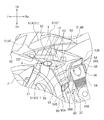
ヘッドパイプ5には、ステアリングシャフト(図示せず)が支持されている。ステアリングシャフトの上部にはハンドル4が設けられている。ステアリングシャフトの下部にはフロントフォーク6が設けられている。フロントフォーク6の下端部には、前輪7が回転自在に支持されている。ヘッドパイプ5の前方には、フロントカバー40が配置されている。図2に示すように、ヘッドパイプ5の側方には、左右のサイドカバー50が配置されている。左のサイドカバー50は、ヘッドパイプ5の左方に配置されている。右のサイドカバー50は、ヘッドパイプ5の右方に配置されている。ヘッドパイプ5の下方には、エアーシュラウド26が配置されている。走行風の一部は、エアーシュラウド26に形成された隙間27を通過して車両後方に流れる。エアーシュラウド26は、左右のサイドカバー50の間に配置されている。
A steering shaft (not shown) is supported on the
図1に示すように、ヘッドパイプ5の後方には、燃料タンク2が配置されている。燃料タンク2は、メインフレーム12に支持されている。燃料タンク2の後方には、乗員が着座するシート3が配置されている。シート3は、ヘッドパイプ5の後方に位置する。シート3は、シートフレーム16に支持されている。シート3は、シートフレーム16の上方に配置されている。シート3は、シートフレーム16に直接的に支持されてもよく、間接的に支持されてもよい。燃料タンク2の一部より下方およびシート3より下方には、左右の車体カバー41が配置されている。左の車体カバー41の右方には、右の車体カバー41(図3参照)が配置されている。右の車体カバー41は、燃料タンク2の一部より下方およびシート3より下方に配置されている。
As shown in FIG. 1, a
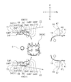
自動二輪車1は、エンジン30を備えている。エンジン30は、クランクケース32と、シリンダボディ34と、シリンダヘッド36と、シリンダヘッドカバー38とを備えている。シリンダボディ34は、クランクケース32の前部から上方に延びている。シリンダヘッド36は、シリンダボディ34の上方に配置され、シリンダボディ34に結合している。シリンダヘッドカバー38は、シリンダヘッド36の上方に配置され、シリンダヘッド36に結合している。エンジン30は、燃料タンク2の下方に配置されている。エンジン30は、ヘッドパイプ5の後方に配置されている。エンジン30は、第1ダウンフレーム14より後方に配置されている。エンジン30は、メインフレーム12の下方に位置する。エンジン30は、第2ダウンフレーム18の前方に位置する。エンジン30は、車体フレーム10に揺動不能に支持されている。すなわち、エンジン30は、第1ダウンフレーム14と第2ダウンフレーム18とに支持されている。図3に示すように、エンジン30は、後述する第2のサイドカバー61の第2縦部64より車幅方向の内方に位置する。
The motorcycle 1 includes an
図1に示すように、自動二輪車1は、排気管90と、サイレンサ92とを備えている。排気管90は、エンジン30に接続されている。詳しくは、排気管90は、シリンダヘッド36の前部に接続されている。排気管90は後方に延びている。詳しくは、排気管90は、シリンダヘッド36から前斜め下向きに延びる第1部分90Aと、第1部分90Aから後斜め下向きに延びる第2部分90Bと、第2部分90Bから後方に延びる第3部分90Cとを備えている。排気管90の後端部にはサイレンサ92が接続されている。
As shown in FIG. 1, the motorcycle 1 includes an
自動二輪車1は、車体フレーム10に連結されたリアアーム22を備えている。リアアーム22は、第2ダウンフレーム18の後方に位置する。リアアーム22は、バックステー20の下方に位置する。第2ダウンフレーム18とリアアーム22とは、ピポット軸24を介して連結されている。リアアーム22は、第2ダウンフレーム18に揺動自在に連結されている。ただし、リアアーム22は、エンジン30に揺動自在に連結されていてもよい。リアアーム22の後端部には、後輪8が回転自在に支持されている。
The motorcycle 1 includes a
図2に示すように、自動二輪車1は、左右のステップ47を備えている。ステップ47には、乗員の足が載せられる。左のステップ47は左方に延び、右のステップ47は右方に延びている。ステップ47は棒状に形成されている。図1に示すように、ステップ47は、第2ダウンフレーム18に取り付けられた支持フレーム19に支持されている。ステップ47は、シート3より下方に位置する。ステップ47は、後述の第2のサイドカバー61の後方に位置する。図3に示すように、ステップ47は、車体カバー41の車幅方向の外方に配置されている。
As shown in FIG. 2, the motorcycle 1 includes left and
図2に示すように、左右のサイドカバー50は、第1のサイドカバー51と、第2のサイドカバー61とを有している。第1のサイドカバー51は、ヘッドパイプ5の車幅方向の外方に配置されている。左の第1のサイドカバー51は、ヘッドパイプ5の左方に配置されている。右の第1のサイドカバー51は、ヘッドパイプ5の右方に配置されている。第2のサイドカバー61は、第1のサイドカバー51の車幅方向の外方に配置されている。左の第2のサイドカバー61は、左の第1のサイドカバー51の左方に配置されている。右の第2のサイドカバー61は、右の第1のサイドカバー51の右方に配置されている。左の第1のサイドカバー51および左の第2のサイドカバー61は、フロントフォーク6の左方に配置されている。右の第1のサイドカバー51および右の第2のサイドカバー61は、フロントフォーク6の右方に配置されている。本実施形態では、左のサイドカバー50と右のサイドカバー50とは同様の形状であるが、かかる形態に限定されない。以下、左のサイドカバー50の構造を説明し、右のサイドカバー50の構造の説明は省略する。
As shown in FIG. 2, the left and right side covers 50 have a
図4に示すように、第1のサイドカバー51は、第1の上サイドカバー51Aと第1の下サイドカバー51Bとを有している。第1の上サイドカバー51Aと第1の下サイドカバー51Bとは異なる材料から成形されている。第1の上サイドカバー51Aと第1の下サイドカバー51Bとは同じ材料から成形されていてもよい。第1の上サイドカバー51Aと第1の下サイドカバー51Bとは一体化されていてもよい。第1の上サイドカバー51Aは、車両前後方向に延びる。第1の下サイドカバー51Bは、第1の上サイドカバー51Aの下方に配置されている。第1の下サイドカバー51Bは、第1ダウンフレーム14に取り付けられている。第1の下サイドカバー51Bの前端52Fは、第1の上サイドカバー51Aの前端51AFより後方に位置する。第1の下サイドカバー51Bの後端52Rは、第1の上サイドカバー51Aの後端51ARより後方に位置する。第1の下サイドカバー51Bは、車両前後方向に延びる第1横部52と、第1横部52から下方に延びる第1縦部54とを有している。第1横部52は、車両側面視でフロントフォーク6と重なる。第1横部52は、車両側面視でヘッドパイプ5と重なる。第1横部52は、車両側面視で第1ダウンフレーム14と重なる。第1横部52は、シリンダヘッド36より上方に位置する。
As shown in FIG. 4, the
第1縦部54は、車両側面視で第1ダウンフレーム14と重なる。第1縦部54は、車両側面視でシリンダヘッド36の一部と重なる。第1縦部54は、車両側面視で排気管90の第1部分90Aと重なる。第1縦部54の下端54Bは、シリンダヘッド36の下端36Bより下方に位置する。第1縦部54の下端54Bは、シリンダボディ34の下端34Bより下方に位置する。第1縦部54は、下方に行くほど車両前後方向の長さが短くなるように形成されている。
The first
第1縦部54には、複数の凸部58が形成されている。図2に示すように、凸部58は、車幅方向の外方に向けて突出している。図4に示すように、凸部58は、車両前後方向に延びる。凸部58は、後部が前部よりも上方に位置するように水平線から傾いている。凸部58は、後部が前部よりも下方に位置するように水平線から傾いていてもよいし、凸部58は、水平線から傾いた状態で配置されなくてもよく、水平方向に配置されてもよい。凸部58は、車両側面視で第1ダウンフレーム14と重なる。凸部58の一部は、車両側面視で後述の第2縦部64(図6参照)とは重ならない。凸部58の全体が、車両側面視で第2縦部64と重なっていてもよい。
A plurality of
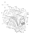
図5に示すように、第1縦部54を横切る水平断面において、第1縦部54の前端部54FPは、車幅方向の内方に向けて延びる。前端部54FPは、前方に行くほど車幅方向の内方に向けて傾斜している。第1縦部54を横切る水平断面において、第1縦部54の後端部54RPは、車幅方向の内方に向けて延びる。後端部54RPは、後方に行くほど車幅方向の内方に向けて傾斜している。第1縦部54を横切る水平断面において、第1縦部54の後端54Rは、第1縦部54の前端54Fより車幅方向の内方に位置する。第1縦部54を横切る水平断面において、第1縦部54は、後述の第2縦部64の前端64Fよりも前方に位置する前端54Fを備える。第1縦部54と、車体カバー41とを横切る水平断面において、第1縦部54は、車体カバー41のうち最も車幅方向の外方に位置する外端41Lより車幅方向の内方に位置する後端部54RPを有する。
As shown in FIG. 5, the
図6に示すように、第2のサイドカバー61は、車両前後方向に延びる第2横部62と、第2横部62から下方に延びる第2縦部64とを有している。第2横部62は、車両側面視で第1のサイドカバー51と重なる。第2横部62は、車両側面視で第1の上サイドカバー51Aと重なる。第2横部62は、車両側面視で第1横部52(図4参照)と重なる。第2横部62は、車両側面視でフロントフォーク6と重なる。第2横部62は、車両側面視でヘッドパイプ5と重なる。第2横部62は、車両側面視で第1ダウンフレーム14と重なる。第2横部62は、シリンダボディ34より上方に位置する。第2横部62の前端62Fは、第1横部52の前端52F(図4参照)より前方に位置する。第2横部62の後端62Rは、第1横部52の後端52Rより前方に位置する。第2横部62の上端62Tは、第1の上サイドカバー51Aの上端51Tより下方に位置する。
As shown in FIG. 6, the
第2縦部64は、車両側面視で第1のサイドカバー51と重なる。第2縦部64は、車両側面視で第1の下サイドカバー51Bと重なる。第2縦部64は、車両側面視で第1縦部54(図4参照)と重なる。第2縦部64は、車両側面視で第1ダウンフレーム14と重なる。第2縦部64は、車両側面視でシリンダヘッド36の一部と重なる。第2縦部64は、車両側面視で排気管90の第1部分90Aと重なる。第2縦部64は、車両側面視で凸部58の一部と重なる。第2縦部64の下端64Bは、シリンダヘッド36の下端36Bより下方に位置する。第2縦部64の下端64Bは、シリンダボディ34の下端34Bより下方に位置する。第2縦部64は、下方に行くほど車両前後方向の長さが短くなるように形成されている。第2縦部64は、車両前後方向の長さが第1縦部54の車両前後方向の長さより短い部分を有する。
The second
図7に示すように、第2縦部64を横切る水平断面において、第2縦部64の前端部64FPは、車幅方向の内方に向けて延びる。前端部64FPは、前方に行くほど車幅方向の内方に向けて傾斜している。第2縦部64を横切る水平断面において、第2縦部64の後端部64RPは、車幅方向の内方に向けて延びる。後端部64RPは、後方に行くほど車幅方向の内方に向けて傾斜している。第2縦部64を横切る水平断面において、第2縦部64の後端64Rは、第2縦部64の前端64Fより車幅方向の内方に位置する。第2縦部64を横切る水平断面において、第2縦部64は、第1縦部54の後端54Rよりも後方に位置する後端64Rを備える。第2縦部64を横切る水平断面において、第2縦部64は、凸部58のうち最も車幅方向の外方に位置する外端58Lより車幅方向の内方に位置する後端64Rを有する。第2縦部64の後端64Rは、凸部58の外端58Lより車幅方向の外方に位置してもよい。図3に示すように、第2縦部64と、車体カバー41とを横切る水平断面において、第2縦部64は、車体カバー41より車幅方向の外方に位置する。
As shown in FIG. 7, the
図6に示すように、第1のサイドカバー51と第2縦部64との間には、走行風が通過する走行風通路70が形成されている。第1の下サイドカバー51Bと第2縦部64との間には、走行風が通過する走行風通路70が形成されている。走行風通路70は、第1のサイドカバー51の第1縦部54(図4参照)と第2のサイドカバー61の第2縦部64との間に形成されている。走行風通路70の上端70Aは、シリンダヘッドカバー38の上端38Aより上方に位置する。走行風通路70の下端70Bは、シリンダヘッド36の下端36Bより下方に位置する。
As shown in FIG. 6, a traveling
図2に示すように、自動二輪車1は、左右のフラッシャランプ80を備える。フラッシャランプ80は、ランプ部82と、連結部84とを有している。連結部84は、ランプ部82と第1のサイドカバー51との間に位置する。連結部84は、ランプ部82と第1のサイドカバー51とを連結する。図6に示すように、フラッシャランプ80は、第1のサイドカバー51のうち車両側面視で第1のサイドカバー51と第2のサイドカバー61とが重ならない位置に取り付けられている。フラッシャランプ80は、第2縦部64の前方の位置に取り付けられている。フラッシャランプ80は、走行風通路70の前方に位置する。フラッシャランプ80は、第2横部62より下方に配置されている。フラッシャランプ80は、フロントフォーク6より後方に位置する。フラッシャランプ80は、第1ダウンフレーム14より前方に位置する。フラッシャランプ80は、凸部58より前方に位置する。フラッシャランプ80の上端80Aは、シリンダヘッドカバー38の上端38Aより上方に位置する。フラッシャランプ80の下端80Bは、シリンダヘッドカバー38の上端38Aより下方に位置する。図2に示すように、フラッシャランプ80は、車両正面視で走行風通路70と重なる。フラッシャランプ80の少なくとも一部は、車両正面視で第2のサイドカバー61の車幅方向の外方に位置する。左のフラッシャランプ80の外端80Pは、車両正面視で第2のサイドカバー61より左方に位置する。右のフラッシャランプ80の外端80Pは、車両正面視で第2のサイドカバー61より右方に位置する。
As shown in FIG. 2, the motorcycle 1 includes left and
フラッシャランプ80の連結部84は、屈曲可能に形成されている。ここで、「屈曲可能」とは、連結部84に外力が加わったときに連結部84が弾性変形して折れ曲がることをいい、連結部84に加わる外力が消滅したときは、連結部84は元の形状に復元することをいう。図8に示すように、連結部84に外力が加えられて連結部84が屈曲したとき、ランプ部82は、車両正面視で、第2のサイドカバー61のうち最も車幅方向の外方に位置する外端61Lより車幅方向の内方に位置する。ランプ部82は、連結部84に加えられる外力がなくなったときは、元の位置に復帰する。
The connecting
次に、走行風の流れについて説明する。走行風は、図3の矢印X1で示すように、フラッシャランプ80に当たる。フラッシャランプ80に当たった走行風には、フラッシャランプ80の後方で乱れが生じる。乱れた走行風は、図6の矢印X2で示すように、フラッシャランプ80の後方に位置する走行風通路70に流れ込む。走行風通路70内において、走行風は整流される。整流された走行風は、第2縦部64の後端部64RP(図3参照)に当たり、図3の矢印X3で示すように、車幅方向の内方へと導かれる。これにより、乗員の脚95に当たる走行風を低減することができる。また、フラッシャランプ80より下方では、図5の矢印Y1に示すように、走行風の一部は走行風通路70内を流れ、第2縦部64の後端部64RPに当たる。後端部64RPに当たった走行風は、図5の矢印Y2に示すように、車幅方向の内方に導かれ、エンジン30に向けて流れる。これにより、乗員の脚95に当たる走行風を低減することができると共に、エンジン30を冷却することができる。一方、走行風の一部は、図5の矢印Z1に示すように、第2縦部64の前端部64FPに当たる。前端部64FPは、前方に行くほど車幅方向の内方に向かうように傾斜しているため、前端部64FPに当たった走行風は、図5の矢印Z2に示すように、第2縦部64の外方へ流れる。これにより、乗員の脚95に当たる走行風を低減することができる。
Next, the flow of traveling wind will be described. The traveling wind strikes the
以上のように、自動二輪車1によれば、図6に示すように、フラッシャランプ80は、第1のサイドカバー51と第2のサイドカバー61の縦部64との間に形成された走行風通路70の前方に位置する。このため、フラッシャランプ80の後方で発生する乱れた走行風は、図6の矢印X2で示すように、走行風通路70へと導かれる。乱れた走行風は、走行風通路70内を通過する際に整流される。乗員の脚95には、乱れた走行風ではなく、整流された走行風が当たることになる。この結果、乗車時の快適性が向上される。
As described above, according to the motorcycle 1, as shown in FIG. 6, the
フラッシャランプ80は、第2のサイドカバー61より車幅方向の内方に配置された第1のサイドカバー51に取り付けられている。このため、フラッシャランプ80を第2のサイドカバー61に取り付けた場合と比較して、自動二輪車1の車幅方向の大型化を抑制することができる。
The
本実施形態に係る自動二輪車1によれば、図5に示すように、エンジン30は、第2縦部64より車幅方向の内方に位置し、第2縦部64を横切る水平断面において、第2縦部64の後端部64RPは、車幅方向の内方に向けて延びる。走行風通路70内を通過する際に整流された走行風は、図5の矢印Y2で示すように、第2縦部64の後端部64RPに当たる。第2縦部64の後端部64RPは、車両平面視で車幅方向の内方に向けて延びているため、整流された走行風は、図5の矢印X2で示すように、車幅方向の内方に導かれる。これにより、乗員の脚95に当たる走行風を低減することができ、乗車時の快適性が向上される。また、整流された走行風は、第2縦部64より車幅方向の内容に位置するエンジン30に導かれる。このため、エンジン30を冷却することができる。
According to the motorcycle 1 according to the present embodiment, as shown in FIG. 5, the
本実施形態に係る自動二輪車1によれば、図5に示すように、第2縦部64の後端64Rは、第2縦部64の前端64Fより車幅方向の内方に位置する。このため、走行風通路70により多くの走行風を導くことができる。この結果、エンジン30により多くの走行風を導くことができ、エンジン30の冷却性能が向上する。
According to the motorcycle 1 according to the present embodiment, the
本実施形態に係る自動二輪車1によれば、図6に示すように、第2縦部64の下端64Bは、シリンダヘッド36の下端36Bよりも下方に位置する。これにより、走行風通路70の上下方向の長さが比較的長くなるため、走行風通路70を通過する走行風が多くなる。これにより、より多くの走行風をエンジン30に導くことができ、エンジン30の冷却性能が向上する。
According to the motorcycle 1 according to the present embodiment, the
本実施形態に係る自動二輪車1によれば、第2縦部64は、車両側面視で、第1ダウンフレーム14と重なる。これにより、走行風通路70の車両前後方向の長さが比較的長くなる。このため、走行風通路70を通過する走行風はより確実に整流される。整流された走行風は、エンジン30に導かれ、エンジン30を冷却することができる。
According to the motorcycle 1 according to the present embodiment, the second
本実施形態に係る自動二輪車1によれば、図5に示すように、第2縦部64は、第1縦部54の後端54Rよりも後方に位置する後端64Rを備える。走行風通路70内を通過し、第2のサイドカバー61の第2縦部64の後端部64RPに当たった走行風は、図5の矢印Y2で示すように、車幅方向の内方により確実に導かれる。これにより、乗員の脚95に当たる走行風を低減することができる。また、走行風をより確実にエンジン30に導くことができるため、エンジン30の冷却性能が向上する。
According to the motorcycle 1 according to the present embodiment, as shown in FIG. 5, the second
本実施形態に係る自動二輪車1によれば、図6に示すように、第1縦部54には、車幅方向の外方に向けて突出し、車両前後方向に延びる凸部58が形成され、凸部58の少なくとも一部は、車両側面視で第2縦部64と重なる。これにより、フラッシャランプ80の後方で発生する乱れた走行風は、走行風通路70内に位置する凸部58によって整流される。これにより、乗員の脚95には、整流された走行風が当たることになり、乗車時の快適性が向上する。
According to the motorcycle 1 according to the present embodiment, as shown in FIG. 6, the first
本実施形態に係る自動二輪車1によれば、図5に示すように、第2縦部64の後端64Rは、凸部58のうち最も車幅方向の外方に位置する外端58Lより車幅方向の内方に位置する。これにより、凸部58によって整流された走行風は車幅方向の内方に導かれる。このため、乗員の脚95に当たる走行風を低減することができる。乗車時の快適性が向上される。
According to the motorcycle 1 according to the present embodiment, as shown in FIG. 5, the
本実施形態に係る自動二輪車1によれば、図3に示すように、第2縦部64と、車体カバー41とを横切る水平断面において、第2縦部64は、車体カバー41より車幅方向の外方に位置する。このため、第2縦部64より車幅方向の外方を通過する走行風は、乗員の脚95に当たりにくくなる。
According to the motorcycle 1 according to the present embodiment, as shown in FIG. 3, in the horizontal section across the second
本実施形態に係る自動二輪車1によれば、図5に示すように、第1縦部54と、車体カバー41とを横切る水平断面において、第1縦部54の少なくとも一部は、車体カバー41のうち最も車幅方向の外方に位置する外端41Lより車幅方向の内方に位置する。このため、走行風通路70を通過する走行風は、車幅方向の内方に導かれる。この結果、走行風は、乗員の脚95に当たりにくくなる。
According to the motorcycle 1 according to the present embodiment, as shown in FIG. 5, at least a part of the first
本実施形態に係る自動二輪車1によれば、図5に示すように、第2縦部64を横切る水平断面において、第2縦部64の前端部64FPは、前方に行くほど車幅方向の内方に向かうように延びる。第2のサイドカバー61の第2縦部64の前方から第2縦部64に向かって流れる走行風は、第2縦部64の前端部64FPに当たる。このため、第2縦部64の前端部64FPに当たった走行風は、図5の矢印Z2で示すように、第2縦部64の外方、即ち第1縦部54とは車幅方向で反対の方へと流れる。これにより、乗員の脚95に当たる走行風を低減することができる。
According to the motorcycle 1 according to the present embodiment, as shown in FIG. 5, the
本実施形態に係る自動二輪車1によれば、図8に示すように、連結部84が屈曲したとき、ランプ部82は、車両正面視で、第2のサイドカバー61のうち最も車幅方向の外方に位置する外端61Lより車幅方向の内方に位置する。これにより、自動二輪車1に対して側方からの力が加わったとき、連結部84は屈曲する。ランプ部82は、連結部84の屈曲によって、第2のサイドカバー61のうち最も車幅方向の外方に位置する外端61Lより車幅方向の内方に位置することができる。このため、側方からの力は第2のサイドカバー61に分散され、フラッシャランプ80に加わる力が低減される。これにより、ランプ部82の破損を防止することができる。
According to the motorcycle 1 according to the present embodiment, as shown in FIG. 8, when the connecting
ここに用いられた用語及び表現は、説明のために用いられたものであって限定的に解釈するために用いられたものではない。ここに示されかつ述べられた特徴事項の如何なる均等物をも排除するものではなく、本発明のクレームされた範囲内における各種変形をも許容するものであると認識されなければならない。本発明は、多くの異なった形態で具現化され得るものである。この開示は本発明の原理の実施形態を提供するものと見なされるべきである。それらの実施形態は、本発明をここに記載しかつ/又は図示した好ましい実施形態に限定することを意図するものではないという了解のもとで、実施形態がここに記載されている。ここに記載した実施形態に限定されるものではない。本発明は、この開示に基づいて当業者によって認識され得る、均等な要素、修正、削除、組み合わせ、改良及び/又は変更を含むあらゆる実施形態をも包含する。クレームの限定事項はそのクレームで用いられた用語に基づいて広く解釈されるべきであり、本明細書あるいは本願のプロセキューション中に記載された実施形態に限定されるべきではない。 The terms and expressions used herein are used for explanation and are not used for limited interpretation. It should be recognized that any equivalents of the features shown and described herein are not excluded and that various modifications within the claimed scope of the invention are permitted. The present invention can be embodied in many different forms. This disclosure should be regarded as providing embodiments of the principles of the invention. The embodiments are described herein with the understanding that the embodiments are not intended to limit the invention to the preferred embodiments described and / or illustrated herein. It is not limited to the embodiment described here. The present invention also encompasses any embodiment that includes equivalent elements, modifications, deletions, combinations, improvements and / or changes that may be recognized by those skilled in the art based on this disclosure. Claim limitations should be construed broadly based on the terms used in the claims and should not be limited to the embodiments described herein or in the process of this application.
5 ヘッドパイプ
14 第1ダウンフレーム
34 シリンダボディ
36 シリンダヘッド
50 サイドカバー
51 第1のサイドカバー
54 第1縦部
58 凸部
61 第2のサイドカバー
64 第2縦部
70 走行風通路
80 フラッシャランプ
5
Claims (12)
前記ヘッドパイプから後方に延びる車体フレームと、
前記ヘッドパイプの後方に位置し、乗員が着座するシートと、
前記ヘッドパイプの車幅方向の外方に配置された第1のサイドカバーと、
車両側面視で前記第1のサイドカバーと重なりかつ下方に延びる縦部を有し、前記第1のサイドカバーの車幅方向の外方に配置された第2のサイドカバーと、
前記第1のサイドカバーのうち車両側面視で前記第1のサイドカバーと前記第2のサイドカバーとが重ならない位置であり、かつ前記縦部より前方の位置に取り付けられ、車両正面視で少なくとも一部が前記第2のサイドカバーの車幅方向の外方に位置するフラッシャランプと、
前記シートより下方かつ前記第2のサイドカバーの後方に位置し、乗員の足を載せるステップと、を備え、
前記第1のサイドカバーと前記縦部との間には、走行風が通過する走行風通路が形成され、
前記フラッシャランプは、前記走行風通路の前方に位置する、自動二輪車。 A head pipe,
A vehicle body frame extending rearward from the head pipe;
A seat located behind the head pipe and seated by an occupant;
A first side cover disposed outside the head pipe in the vehicle width direction;
A second side cover that has a vertical portion that overlaps with the first side cover and extends downward in a vehicle side view, and is disposed outward in the vehicle width direction of the first side cover;
The first side cover of the first side cover is a position where the first side cover and the second side cover do not overlap with each other in a side view of the vehicle, and is attached to a position in front of the vertical portion, and at least in a front view of the vehicle A flasher lamp partially located outside the second side cover in the vehicle width direction;
A step that is located below the seat and behind the second side cover, and places the occupant's feet,
Between the first side cover and the vertical portion, a traveling wind passage through which traveling wind passes is formed,
The flasher lamp is a motorcycle located in front of the traveling wind passage.
前記エンジンは、前記縦部より車幅方向の内方に位置し、
前記縦部を横切る水平断面において、前記縦部の後端部は、車幅方向の内方に向けて延びる、請求項1に記載の自動二輪車。 It is located behind the head pipe and includes an engine supported by the body frame,
The engine is located inward in the vehicle width direction from the vertical portion,
2. The motorcycle according to claim 1, wherein a rear end portion of the vertical portion extends inward in a vehicle width direction in a horizontal cross section crossing the vertical portion.
前記縦部の下端は、前記シリンダヘッドの下端よりも下方に位置する、請求項2または3に記載の自動二輪車。 The engine includes a crankcase, a cylinder body extending upward from the crankcase, and a cylinder head coupled to the cylinder body,
The motorcycle according to claim 2 or 3, wherein a lower end of the vertical portion is positioned below a lower end of the cylinder head.
前記縦部は、前記他の縦部の後端よりも後方に位置する後端を備える、請求項2から5のいずれか一項に記載の自動二輪車。 The first side cover has another vertical portion that overlaps the vertical portion in a vehicle side view,
The motorcycle according to any one of claims 2 to 5, wherein the vertical portion includes a rear end positioned rearward of a rear end of the other vertical portion.
前記凸部の少なくとも一部は、車両側面視で前記縦部と重なる、請求項6に記載の自動二輪車。 In the other vertical portion, a convex portion that protrudes outward in the vehicle width direction and extends in the vehicle front-rear direction is formed.
The motorcycle according to claim 6, wherein at least a part of the convex portion overlaps the vertical portion in a side view of the vehicle.
前記縦部と、前記車体カバーとを横切る水平断面において、前記縦部は、前記車体カバーより車幅方向の外方に位置する、請求項6から8のいずれか一項に記載の自動二輪車。 A vehicle body cover disposed inward in the vehicle width direction of the step;
The motorcycle according to any one of claims 6 to 8, wherein the vertical portion is located outward of the vehicle body cover in the vehicle width direction in a horizontal cross section that crosses the vertical portion and the vehicle body cover.
前記連結部は、屈曲可能であり、
前記連結部が屈曲したとき、前記ランプ部は、車両正面視で、前記第2のサイドカバーのうち最も車幅方向の外方に位置する外端より車幅方向の内方に位置する、請求項1から11のいずれか一項に記載の自動二輪車。 The flasher lamp has a lamp part, and a connecting part that is located between the lamp part and the first side cover and connects the lamp part and the first side cover,
The connecting portion is bendable,
When the connecting portion is bent, the ramp portion is located inward in the vehicle width direction from an outer end located most outward in the vehicle width direction of the second side cover in a front view of the vehicle. Item 12. The motorcycle according to any one of items 1 to 11.
Priority Applications (4)
| Application Number | Priority Date | Filing Date | Title |
|---|---|---|---|
| JP2013267464A JP2015123765A (en) | 2013-12-25 | 2013-12-25 | Motor cycle |
| ES14169185.7T ES2588074T3 (en) | 2013-12-25 | 2014-05-21 | Motorcycle |
| EP14169185.7A EP2889207B1 (en) | 2013-12-25 | 2014-05-21 | Motorcycle |
| ARP140102468A AR096790A1 (en) | 2013-12-25 | 2014-07-02 | MOTORCYCLE |
Applications Claiming Priority (1)
| Application Number | Priority Date | Filing Date | Title |
|---|---|---|---|
| JP2013267464A JP2015123765A (en) | 2013-12-25 | 2013-12-25 | Motor cycle |
Publications (1)
| Publication Number | Publication Date |
|---|---|
| JP2015123765A true JP2015123765A (en) | 2015-07-06 |
Family
ID=50732938
Family Applications (1)
| Application Number | Title | Priority Date | Filing Date |
|---|---|---|---|
| JP2013267464A Pending JP2015123765A (en) | 2013-12-25 | 2013-12-25 | Motor cycle |
Country Status (4)
| Country | Link |
|---|---|
| EP (1) | EP2889207B1 (en) |
| JP (1) | JP2015123765A (en) |
| AR (1) | AR096790A1 (en) |
| ES (1) | ES2588074T3 (en) |
Cited By (4)
| Publication number | Priority date | Publication date | Assignee | Title |
|---|---|---|---|---|
| JP2018052413A (en) * | 2016-09-30 | 2018-04-05 | スズキ株式会社 | Air guide structure of saddle-riding type vehicle |
| JP2018202932A (en) * | 2017-05-31 | 2018-12-27 | 本田技研工業株式会社 | Saddle-riding type vehicle |
| WO2022059679A1 (en) * | 2020-09-18 | 2022-03-24 | ヤマハ発動機株式会社 | Straddled vehicle |
| JP7450489B2 (en) | 2020-07-30 | 2024-03-15 | カワサキモータース株式会社 | motorcycle |
Families Citing this family (3)
| Publication number | Priority date | Publication date | Assignee | Title |
|---|---|---|---|---|
| CN107878619B (en) * | 2016-09-30 | 2020-08-18 | 雅马哈发动机株式会社 | Saddle-riding type vehicle |
| JP6663949B2 (en) | 2018-03-30 | 2020-03-13 | 本田技研工業株式会社 | Saddle-type vehicle |
| JP2024041147A (en) | 2022-09-14 | 2024-03-27 | 本田技研工業株式会社 | saddle type vehicle |
Family Cites Families (5)
| Publication number | Priority date | Publication date | Assignee | Title |
|---|---|---|---|---|
| US4887688A (en) * | 1987-08-06 | 1989-12-19 | Honda Giken Kogyo Kabushiki Kaisha | Motorcycle |
| JP5129672B2 (en) * | 2008-07-07 | 2013-01-30 | 本田技研工業株式会社 | Body cover structure for motorcycles |
| EP2311717B1 (en) * | 2008-08-08 | 2014-02-12 | Honda Motor Co., Ltd. | Vehicle |
| JP2012162094A (en) | 2009-05-27 | 2012-08-30 | Yamaha Motor Co Ltd | Motorcycle |
| JP5486978B2 (en) * | 2010-03-25 | 2014-05-07 | 本田技研工業株式会社 | Motorcycle cowl structure |
-
2013
- 2013-12-25 JP JP2013267464A patent/JP2015123765A/en active Pending
-
2014
- 2014-05-21 EP EP14169185.7A patent/EP2889207B1/en active Active
- 2014-05-21 ES ES14169185.7T patent/ES2588074T3/en active Active
- 2014-07-02 AR ARP140102468A patent/AR096790A1/en active IP Right Grant
Cited By (4)
| Publication number | Priority date | Publication date | Assignee | Title |
|---|---|---|---|---|
| JP2018052413A (en) * | 2016-09-30 | 2018-04-05 | スズキ株式会社 | Air guide structure of saddle-riding type vehicle |
| JP2018202932A (en) * | 2017-05-31 | 2018-12-27 | 本田技研工業株式会社 | Saddle-riding type vehicle |
| JP7450489B2 (en) | 2020-07-30 | 2024-03-15 | カワサキモータース株式会社 | motorcycle |
| WO2022059679A1 (en) * | 2020-09-18 | 2022-03-24 | ヤマハ発動機株式会社 | Straddled vehicle |
Also Published As
| Publication number | Publication date |
|---|---|
| EP2889207B1 (en) | 2016-08-17 |
| EP2889207A1 (en) | 2015-07-01 |
| ES2588074T3 (en) | 2016-10-28 |
| AR096790A1 (en) | 2016-02-03 |
Similar Documents
| Publication | Publication Date | Title |
|---|---|---|
| JP2015123765A (en) | Motor cycle | |
| JP4584781B2 (en) | Cowling structure for motorcycles | |
| JP4856485B2 (en) | Motorcycle cowling structure | |
| JP3157145U (en) | Motorcycle | |
| JP5771100B2 (en) | Saddle riding vehicle | |
| JP2011152848A (en) | Cowling structure of saddle-riding type vehicle | |
| JP3154590U (en) | Motorcycle | |
| JP6196083B2 (en) | Motorcycle | |
| US8087485B2 (en) | Straddle-type vehicle | |
| JP2012017087A (en) | Saddle-ride type vehicle | |
| JP3157144U (en) | Motorcycle | |
| JP5837777B2 (en) | Saddle riding vehicle | |
| JP2015227102A (en) | Saddle-riding type vehicle | |
| US9045188B2 (en) | Lower part structure for vehicle | |
| JP5576308B2 (en) | Saddle riding | |
| JP5404319B2 (en) | Motorcycle | |
| JP2009083676A (en) | Motorcycle air intake port structure | |
| JP4684793B2 (en) | Vehicle front cover structure | |
| WO2018225199A1 (en) | Saddled vehicle | |
| JP3157143U (en) | Motorcycle | |
| JP3155302U (en) | Motorcycle | |
| JP2020015386A (en) | Saddle riding type vehicle | |
| WO2019065485A1 (en) | Outer cover component structure for saddled vehicles | |
| JP2018162040A (en) | Saddle-riding type vehicle | |
| JP4394551B2 (en) | Radiator arrangement structure of motorcycle |