JP2015121608A - Printing system, printing method, and program - Google Patents
Printing system, printing method, and program Download PDFInfo
- Publication number
- JP2015121608A JP2015121608A JP2013264239A JP2013264239A JP2015121608A JP 2015121608 A JP2015121608 A JP 2015121608A JP 2013264239 A JP2013264239 A JP 2013264239A JP 2013264239 A JP2013264239 A JP 2013264239A JP 2015121608 A JP2015121608 A JP 2015121608A
- Authority
- JP
- Japan
- Prior art keywords
- recording medium
- image
- roll
- image forming
- shaped recording
- Prior art date
- Legal status (The legal status is an assumption and is not a legal conclusion. Google has not performed a legal analysis and makes no representation as to the accuracy of the status listed.)
- Pending
Links
Images


Classifications
-
- B—PERFORMING OPERATIONS; TRANSPORTING
- B65—CONVEYING; PACKING; STORING; HANDLING THIN OR FILAMENTARY MATERIAL
- B65H—HANDLING THIN OR FILAMENTARY MATERIAL, e.g. SHEETS, WEBS, CABLES
- B65H18/00—Winding webs
- B65H18/02—Supporting web roll
- B65H18/026—Cantilever type
-
- B—PERFORMING OPERATIONS; TRANSPORTING
- B65—CONVEYING; PACKING; STORING; HANDLING THIN OR FILAMENTARY MATERIAL
- B65H—HANDLING THIN OR FILAMENTARY MATERIAL, e.g. SHEETS, WEBS, CABLES
- B65H18/00—Winding webs
- B65H18/08—Web-winding mechanisms
- B65H18/10—Mechanisms in which power is applied to web-roll spindle
- B65H18/103—Reel-to-reel type web winding and unwinding mechanisms
-
- G—PHYSICS
- G03—PHOTOGRAPHY; CINEMATOGRAPHY; ANALOGOUS TECHNIQUES USING WAVES OTHER THAN OPTICAL WAVES; ELECTROGRAPHY; HOLOGRAPHY
- G03G—ELECTROGRAPHY; ELECTROPHOTOGRAPHY; MAGNETOGRAPHY
- G03G15/00—Apparatus for electrographic processes using a charge pattern
- G03G15/65—Apparatus which relate to the handling of copy material
- G03G15/6517—Apparatus for continuous web copy material of plain paper, e.g. supply rolls; Roll holders therefor
- G03G15/652—Feeding a copy material originating from a continuous web roll
-
- G—PHYSICS
- G03—PHOTOGRAPHY; CINEMATOGRAPHY; ANALOGOUS TECHNIQUES USING WAVES OTHER THAN OPTICAL WAVES; ELECTROGRAPHY; HOLOGRAPHY
- G03G—ELECTROGRAPHY; ELECTROPHOTOGRAPHY; MAGNETOGRAPHY
- G03G15/00—Apparatus for electrographic processes using a charge pattern
- G03G15/65—Apparatus which relate to the handling of copy material
- G03G15/6529—Transporting
-
- B—PERFORMING OPERATIONS; TRANSPORTING
- B65—CONVEYING; PACKING; STORING; HANDLING THIN OR FILAMENTARY MATERIAL
- B65H—HANDLING THIN OR FILAMENTARY MATERIAL, e.g. SHEETS, WEBS, CABLES
- B65H2301/00—Handling processes for sheets or webs
- B65H2301/40—Type of handling process
- B65H2301/41—Winding, unwinding
- B65H2301/414—Winding
- B65H2301/4146—Winding involving particular drive arrangement
- B65H2301/41461—Winding involving particular drive arrangement centre drive
-
- B—PERFORMING OPERATIONS; TRANSPORTING
- B65—CONVEYING; PACKING; STORING; HANDLING THIN OR FILAMENTARY MATERIAL
- B65H—HANDLING THIN OR FILAMENTARY MATERIAL, e.g. SHEETS, WEBS, CABLES
- B65H2511/00—Dimensions; Position; Numbers; Identification; Occurrences
- B65H2511/50—Occurence
- B65H2511/51—Presence
- B65H2511/512—Marks, e.g. invisible to the human eye; Patterns
-
- B—PERFORMING OPERATIONS; TRANSPORTING
- B65—CONVEYING; PACKING; STORING; HANDLING THIN OR FILAMENTARY MATERIAL
- B65H—HANDLING THIN OR FILAMENTARY MATERIAL, e.g. SHEETS, WEBS, CABLES
- B65H2801/00—Application field
- B65H2801/03—Image reproduction devices
- B65H2801/06—Office-type machines, e.g. photocopiers
-
- G—PHYSICS
- G03—PHOTOGRAPHY; CINEMATOGRAPHY; ANALOGOUS TECHNIQUES USING WAVES OTHER THAN OPTICAL WAVES; ELECTROGRAPHY; HOLOGRAPHY
- G03G—ELECTROGRAPHY; ELECTROPHOTOGRAPHY; MAGNETOGRAPHY
- G03G15/00—Apparatus for electrographic processes using a charge pattern
- G03G15/01—Apparatus for electrographic processes using a charge pattern for producing multicoloured copies
- G03G15/0142—Structure of complete machines
-
- G—PHYSICS
- G03—PHOTOGRAPHY; CINEMATOGRAPHY; ANALOGOUS TECHNIQUES USING WAVES OTHER THAN OPTICAL WAVES; ELECTROGRAPHY; HOLOGRAPHY
- G03G—ELECTROGRAPHY; ELECTROPHOTOGRAPHY; MAGNETOGRAPHY
- G03G2215/00—Apparatus for electrophotographic processes
- G03G2215/00016—Special arrangement of entire apparatus
- G03G2215/00021—Plural substantially independent image forming units in cooperation, e.g. for duplex, colour or high-speed simplex
-
- G—PHYSICS
- G03—PHOTOGRAPHY; CINEMATOGRAPHY; ANALOGOUS TECHNIQUES USING WAVES OTHER THAN OPTICAL WAVES; ELECTROGRAPHY; HOLOGRAPHY
- G03G—ELECTROGRAPHY; ELECTROPHOTOGRAPHY; MAGNETOGRAPHY
- G03G2215/00—Apparatus for electrophotographic processes
- G03G2215/00362—Apparatus for electrophotographic processes relating to the copy medium handling
- G03G2215/00443—Copy medium
- G03G2215/00451—Paper
- G03G2215/00455—Continuous web, i.e. roll
Landscapes
- Physics & Mathematics (AREA)
- General Physics & Mathematics (AREA)
- Color Electrophotography (AREA)
- Control Or Security For Electrophotography (AREA)
- Electrophotography Configuration And Component (AREA)
- Accessory Devices And Overall Control Thereof (AREA)
Abstract
Description
本発明は、印刷システム、印刷方法及びプログラムに関する。 The present invention relates to a printing system, a printing method, and a program.
プリンタや複写機、ファクシミリ等の画像形成装置が画像形成するための記録媒体として、用紙やフィルム等の記録媒体がロール状に巻かれたロール状記録媒体(以下、「ロール紙」という)がある。ロール紙は、大きなものでもカットの必要がなく収納できるため、例えば多数のラベルやシールを連続して印刷するラベルプリンタのように、大面積の画像形成を切れ目なく行う場合によく用いられる。 As a recording medium for forming an image by an image forming apparatus such as a printer, a copying machine, or a facsimile, there is a roll-shaped recording medium (hereinafter referred to as “roll paper”) in which a recording medium such as paper or film is wound in a roll shape. . Since roll paper can be stored without being cut even when it is large, it is often used when a large area image is formed seamlessly, such as a label printer that continuously prints a large number of labels and stickers.
近年のデジタル印刷の高品質化に伴って、ロール紙を用いた大面積の印刷においても、フレキソ印刷、グラビア印刷、オフセット印刷等の通常の高品質の印刷物に近いレベルの品質が要求されている。そのために、例えば一般的な電子写真式で4連タンデム方式のカラープリンタで使用可能なYMCK(イエロー(Y)、マゼンタ(M)、シアン(C)、ブラック(K))の4色に加えて、白色、透明、その他の色でもロール紙への印刷を可能にすることが求められている。 Along with the recent improvement in quality of digital printing, even in large-area printing using roll paper, quality close to that of ordinary high-quality printed materials such as flexographic printing, gravure printing, and offset printing is required. . Therefore, for example, in addition to four colors of YMCK (yellow (Y), magenta (M), cyan (C), and black (K)) that can be used in a general electrophotographic quadruple tandem color printer. In addition, white, transparent, and other colors are required to enable printing on roll paper.
カラープリンタにおいてYMCKの4色に白色等の他色を追加する方法として、4連タンデム方式のプリンタの代わりに5連以上のタンデム方式に対応したプリンタを用意する方法がある。例えば特許文献1は、透明トナーを用いてユーザが望む光沢感を付加した画像を出力することが可能な5連タンデム方式の画像形成装置を開示している。
As a method of adding other colors such as white to the four colors of YMCK in a color printer, there is a method of preparing a printer corresponding to five or more tandem systems instead of a four-series tandem printer. For example,
また、YMCKのうちのK色(ブラック)をYMCの3色を重ねることで生成し(プロセスブラック)、K色の代わりに他色を追加する方法もある。この方法を用いる場合、4連タンデム方式のプリンタでも他色を追加することが可能になる。 Also, there is a method of generating K color (black) of YMCK by overlapping three colors of YMC (process black) and adding other colors instead of K color. When this method is used, other colors can be added even in a quadruple tandem printer.
しかしながら、5連以上のタンデム方式のプリンタを用いる方法は、専用のプリンタを用意することを要し、装置の大型化とコストの高騰とを招く。一方で、他の複数色を重ねてK色(ブラック)を生成する方法は、複数色を重ねる際のずれが生じる等の原因により、K色1色を用いた場合に比べて品質の低下を招く。 However, the method using a tandem type printer having five or more stations requires preparation of a dedicated printer, resulting in an increase in the size of the apparatus and an increase in cost. On the other hand, the method of generating a K color (black) by superimposing a plurality of other colors causes a deterioration in quality compared to the case of using a single K color due to a cause such as a shift when a plurality of colors are superimposed. Invite.
さらには、例えば5色、6色等、記録媒体上に一度に多くの色の現像剤を重ねて現像剤の層厚が増すと、現像剤を定着させる定着装置に大きな負担をかけ、定着精度の悪化につながる。これを避けるためには、例えば1色当たりの現像剤の濃度を落とす、あるいは多くの色の現像剤を重ねた部分の定着速度を落として重点的に定着させる、といった方法が考えられるが、印刷品質や印刷速度の低下につながる。 Furthermore, for example, when a large number of developers such as 5 colors and 6 colors are stacked on the recording medium at a time to increase the developer layer thickness, a large burden is placed on the fixing device for fixing the developer, and the fixing accuracy is increased. Leads to worsening. In order to avoid this, for example, a method of reducing the concentration of the developer per color, or reducing the fixing speed of a portion where a large number of color developers are overlapped, and fixing the toner intensively can be considered. This leads to a decrease in quality and printing speed.
本発明は、以上のような課題を解決するためのものであり、ロール状記録媒体への高品質な多色印刷を簡便な方法で実現することが可能な印刷システム、印刷方法及びプログラムを提供することを目的とする。 The present invention is to solve the above-described problems, and provides a printing system, a printing method, and a program capable of realizing high-quality multicolor printing on a roll-shaped recording medium by a simple method. The purpose is to do.
上記目的を達成するため、本発明に係る印刷システムは、
第1の巻き出し手段により巻き出されたロール状記録媒体に、画像データに基づいて第1の現像剤像を転写する第1の画像形成手段と、
前記第1の画像形成手段が前記第1の現像剤像を転写した前記ロール状記録媒体を、前記ロール状記録媒体の始端から終端への順に、巻き取り軸の周りに巻き取る第1の巻き取り手段と、
前記第1の巻き取り手段が前記巻き取り軸の周りに巻き取った前記ロール状記録媒体を、前記ロール状記録媒体の前記終端から前記始端への順に、巻き出す第2の巻き出し手段と、
前記第2の巻き出し手段により巻き出された前記ロール状記録媒体の前記第1の現像剤像が転写された領域に、画像が上下反転し、且つ、左右反転した画像データに基づいて第2の現像剤像を転写する第2の画像形成手段と、
を備える、
ことを特徴とする。
In order to achieve the above object, a printing system according to the present invention includes:
A first image forming means for transferring a first developer image based on the image data to a roll-shaped recording medium unwound by the first unwinding means;
A first winding for winding the roll-shaped recording medium onto which the first developer image has been transferred by the first image forming unit around a winding shaft in order from the start end to the end of the roll-shaped recording medium. Taking means,
A second unwinding means for unwinding the roll-shaped recording medium wound around the winding shaft by the first winding means in order from the end to the starting end of the roll-shaped recording medium;
The image is inverted upside down in the area where the first developer image of the roll-shaped recording medium unwound by the second unwinding means is transferred, and second on the basis of the image data which is horizontally reversed. A second image forming means for transferring the developer image of
Comprising
It is characterized by that.
また、上記目的を達成するため、本発明に係る印刷方法は、
巻き出されたロール状記録媒体に、画像データに基づいて第1の現像剤像を転写し、
前記第1の現像剤像を転写した前記ロール状記録媒体を、前記ロール状記録媒体の始端から終端への順に、巻き取り軸の周りに巻き取り、
前記巻き取り軸の周りに巻き取った前記ロール状記録媒体を、前記ロール状記録媒体の前記終端から前記始端への順に、巻き出し、
巻き出された前記ロール状記録媒体の前記第1の現像剤像が転写された領域に、画像が上下反転し、且つ、左右反転した画像データに基づいて第2の現像剤像を転写する、
ことを特徴とする。
In order to achieve the above object, a printing method according to the present invention includes:
The first developer image is transferred to the unrolled roll-shaped recording medium based on the image data,
The roll-shaped recording medium to which the first developer image has been transferred is wound around a winding shaft in order from the start end to the end of the roll-shaped recording medium,
The roll-shaped recording medium wound around the winding shaft is unwound in order from the end to the start end of the roll-shaped recording medium,
The image is inverted upside down and transferred to the second developer image on the basis of the image data obtained by reversing the left and right sides of the rolled recording medium on which the first developer image is transferred.
It is characterized by that.
また、上記目的を達成するため、本発明に係るプログラムは、
コンピュータに、
巻き出されたロール状記録媒体に、画像データに基づいて第1の現像剤像を転写させ、
前記第1の現像剤像を転写させた前記ロール状記録媒体を、前記ロール状記録媒体の始端から終端への順に、巻き取り軸の周りに巻き取らせ、
前記巻き取り軸の周りに巻き取らせた前記ロール状記録媒体を、前記ロール状記録媒体の前記終端から前記始端への順に、巻き出させ、
巻き出された前記ロール状記録媒体の前記第1の現像剤像が転写された領域に、画像が上下反転し、且つ、左右反転した画像データに基づいて第2の現像剤像を転写させる、
ことを特徴とする。
In order to achieve the above object, a program according to the present invention provides:
On the computer,
The first developer image is transferred to the unrolled roll-shaped recording medium based on the image data,
The roll-shaped recording medium to which the first developer image is transferred is wound around a winding shaft in order from the start end to the end of the roll-shaped recording medium,
The rolled recording medium wound around the winding shaft is unwound in order from the end to the starting end of the rolled recording medium,
The image is inverted upside down and transferred to the second developer image on the basis of the image data inverted in the left and right direction in the area where the first developer image of the rolled recording medium is transferred.
It is characterized by that.
本発明によれば、ロール状記録媒体への高品質な多色印刷を簡便な方法で実現することが可能な印刷システム、印刷方法及びプログラムを提供することができる。 According to the present invention, it is possible to provide a printing system, a printing method, and a program capable of realizing high-quality multicolor printing on a roll-shaped recording medium by a simple method.
以下、本発明の実施形態について、図面を参照して説明する。なお、図中同一又は相当する部分には同一符号を付す。 Hereinafter, embodiments of the present invention will be described with reference to the drawings. In the drawings, the same or corresponding parts are denoted by the same reference numerals.
(実施形態1)
図1に実施形態1に係る印刷システムの構成を示す。印刷システム100は、給紙装置1aと画像形成装置2aと巻き取り装置9aとによって構成される通常色印刷システム10aと、給紙装置1bと画像形成装置2bと巻き取り装置9bとによって構成される特別色印刷システム10bと、を備える。印刷システム100は、通常色印刷システム10aと特別色印刷システム10bとを用いて、ロール状記録媒体であるロール紙3に多色印刷する。
(Embodiment 1)
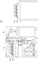
FIG. 1 shows the configuration of a printing system according to the first embodiment. The
通常色印刷システム10aが備える給紙装置1aは、ロール紙3を画像形成装置2aに供給する。給紙装置1aは、所定の巻き芯(紙管)の周りに用紙がロール状に巻き回されたロール紙3を連続的に巻き出して、所定の搬送経路に沿って画像形成装置2aへと搬送する。具体的には、給紙装置1aは、スライド台7aと、保持部8aと、斜行検知センサ11aと、サイドガイド12aと、搬送ローラ対13aと、オートカッタ14aと、マークセンサ15aと、進入ローラ対16aと、進入センサ17aと、を備える。
The
保持部8aは、第1の保持手段として機能し、画像形成装置2aにより画像形成される前のロール紙3を保持する。保持部8aは、ロール紙3の巻き中心にある巻き芯を貫通してロール紙3を保持する回転可能な回転軸(シャフト)と、この回転軸を支持する支持台と、によって構成され、ロール紙3を回転可能に保持する。
The holding
保持部8aには、回転軸を回転させるための不図示のモータが搭載される。保持部8aは、このモータの駆動により指示された単位時間当たりの回転数(単位時間当たりに回転する回数)で回転軸を回転させて、保持しているロール紙3を巻き出すアンワインダとして機能する。
A motor (not shown) for rotating the rotating shaft is mounted on the holding
また、保持部8aの回転軸には、不図示のパウダブレーキが取り付けられる。パウダブレーキは、保持部8aから巻き出されて搬送されているロール紙3にかかるテンション(張力)が一定に保たれるように、回転軸の回転にブレーキを加える。パウダブレーキの機能により、保持部8aから巻き出されたロール紙3は、たるむことなく安定して搬送される。
Further, a powder brake (not shown) is attached to the rotating shaft of the holding
スライド台7aは、両サイドにスライドベアリングを備え、保持部8aを回転軸方向(ロール紙3の幅方向)にスライドさせる。スライド台7aは、斜行検知センサ11aが給紙装置1a内部を搬送されるロール紙3の斜行を検知すると、アクチュエータにより駆動力を得て、検知した斜行を打ち消す方向に保持部8aを移動させる。
The slide table 7a includes slide bearings on both sides, and slides the holding
斜行検知センサ11aは、給紙装置1a内部を搬送されるロール紙3の斜行を検知する。具体的には、斜行検知センサ11aは、ロール紙3の幅方向の端部を挟むように互いに向かい合って配置された複数の組の発光素子と受光素子とによって構成される。斜行検知センサ11aは、この複数の組のそれぞれについて発光素子から発せられた光が遮断されずに受光素子によって受光されたか否かを判別することにより、ロール紙3の端部の幅方向への位置ずれを、ロール紙3に接触することなく測定する。
The
搬送ロール対13aは、保持部8aから巻き出され、従動ローラ及びサイドガイド12aを経由して搬送されたロール紙3を挟持して搬送し、進入ローラ対16aへと供給する。進入ローラ対16aは、搬送ローラ対13aから供給されたロール紙3を挟持して搬送し、画像形成装置2aへと供給する。
The
オートカッタ14aは、必要に応じてロール紙3をカットする。オートカッタ14aは、例えば画像形成装置2aにおける画像形成に必要な長さのロール紙3を搬送し終えたときに、ロール紙3の終端(後端)をカットする。
The
マークセンサ15aは、ロール紙3の表面に記録された、画像形成装置2aが画像形成するための位置基準として用いられるオリジナルマークを検知する。オリジナルマークの詳細については、後述する。
The
進入センサ17aは、進入ローラ対16aから画像形成装置2aへと進入するロール紙3の始端(前端)を検知する。具体的には、進入センサ17aは、発光素子と受光素子とによって構成され、発光素子から発せられた光がロール紙3の始端により遮られて受光素子により検知されなくなると、ロール紙3の始端を検知したと判別する。進入センサ17aがロール紙3の始端を検知すると、画像形成装置2aは、各種ローラ対の駆動を開始して、内部に進入したロール紙3を搬送させる。
The
なお、給紙装置1aの右側における破線で示した領域は、例えばロール紙やトナー等の消耗品の収納に用いられる。
An area indicated by a broken line on the right side of the
特別色印刷システム10bが備える給紙装置1bは、画像形成用の記録媒体としてのロール紙3を、画像形成装置2bに供給する。具体的には、給紙装置1bは、スライド台7bと、保持部8bと、斜行検知センサ11bと、サイドガイド12bと、搬送ローラ対13bと、オートカッタ14bと、マークセンサ15bと、進入ローラ対16bと、進入センサ17bと、を備える。保持部8bは、第2の保持手段として機能し、第1の画像形成装置2aにより画像形成され、巻き取り装置9aにより巻き取られた後のロール紙3を保持する。給紙装置1bは、上述した給紙装置1aと同等の構成を有するため、給紙装置1bが備える各構成要素については詳細な説明を省略する。
The
通常色印刷システム10aが備える巻き取り装置9aは、第1の巻き取り手段(第1のリワインダ)として機能し、画像形成装置2aから排出されたロール紙3を、巻き取り軸91aの周りに巻き取って保持する。同様に、特別色印刷システム10bが備える巻き取り装置9bは、第2の巻き取り手段(第2のリワインダ)として機能し、画像形成装置2bから排出されたロール紙3を、巻き取り軸91bの周りに巻き取って保持する。
The winding
通常色印刷システム10aが備える画像形成装置2aは、給紙装置1aの上に据え置かれ、印刷対象の画像データに基づいてYMCK(イエロー(Y)、マゼンタ(M)、シアン(C)、ブラック(K))の4色の現像剤による第1の現像剤像を形成し、給紙装置1aから供給されるロール紙3に第1の現像剤像を転写する第1の画像形成手段として機能する。特別色印刷システム10bが備える画像形成装置2bは、給紙装置1bの上に据え置かれ、YMCKの4色に含まれない特別色の現像剤による第2の現像剤像を形成し、給紙装置1bから供給されるロール紙3に第2の現像剤像を転写する第2の画像形成手段として機能する。
The
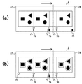
図2を参照して、画像形成装置2a及び画像形成装置2bの内部構成を説明する。以下では、画像形成装置2a及び画像形成装置2bとして、電子写真式で二次転写方式のタンデム型のカラープリンタを例にとって説明する。また、以下では、トナーを現像剤として用いる場合を例にとって説明する。
The internal configuration of the
図2(a)に示すように、画像形成装置2aは、画像形成部20aと、中間転写ベルトユニット30aと、定着装置40aと、を備える。
As shown in FIG. 2A, the
画像形成部20aは、4つの画像形成ユニット21y、21m、21c、21kが直列して設置された構成を備える。画像形成ユニット21y、21m、21cは、それぞれ減法混色の三原色であるイエロー(Y)、マゼンタ(M)、シアン(C)のカラートナーによるカラー画像を形成する。一方、画像形成ユニット21kは、主として文字や画像の暗黒部分等に用いられるブラック(K)トナーによるモノクロ画像を形成する。
The
各画像形成ユニット21は、最下部に感光体ドラム22を備える。この感光体ドラム22は、その周面が例えば有機光導電性材料で構成される。感光体ドラム22の近傍には、周面を取り巻くように、クリーナ23、帯電ローラ24、光書込ヘッド25、及び現像器26の現像ローラ27が配置される。
Each
現像器26は、上部に設置されたトナー容器にイエロー(Y)、マゼンタ(M)、シアン(C)、ブラック(K)のいずれかのトナーを収容し、中間部には下部へのトナー補給機構を備え、下部には現像ローラ27を備える。現像器26は、さらに内部にトナー撹拌部材、現像ローラ27にトナーを供給するトナー供給ローラ、現像ローラ27上のトナー層を一定の層厚に規制するドクターブレード等を備える。
The developing
なお、図2ではイエロー(Y)用の画像形成ユニット21yの構成にのみ符号を付しているが、各画像形成ユニット21は、トナー容器に収納されたトナーの色を除いて同じ構成を有する。
In FIG. 2, only the configuration of the
中間転写ベルトユニット30aは、画像形成装置2a内部のほぼ中央で扁平なループ状になって延在する無端状の転写ベルト31、この転写ベルト31を掛け渡されて転写ベルト31を反時計回り方向に循環させて移動させる駆動ローラ32、及び従動ローラ33を備える。転写ベルト31は、直接ベルト面に転写(一次転写)されたトナー像を、ロール紙3に転写(二次転写)すべくロール紙3への転写位置まで搬送する。
The intermediate
中間転写ベルトユニット30aは、転写ベルト31のループ内に、4個の画像形成ユニット21y、21m、21c、21kに対応する4個の一次転写ローラ34を備える。一次転写ローラ34は、それぞれ、転写ベルト31を介して感光体ドラム22の下部周面に押圧するための導電性発泡スポンジによって構成され、指示された回転周期で回転し、転写ベルト31を感光体ドラム22に当接させたり感光体ドラム22から離接させたりする。
The intermediate
待機搬送ローラ対35は、給紙装置1から拡張給紙用進入口を通って供給されたロール紙3を受け取り、受け取ったロール紙3を二次転写ローラ36へと搬送する。二次転写ローラ36は、転写ベルト31を介して従動ローラ33に圧接するように配設されており、転写ベルト31のベルト面に転写されたトナー像をロール紙3へ二次転写する二次転写部を形成する。
The standby
定着装置40aは、ヒータ41を内蔵した加熱ローラ42と、この加熱ローラ42に圧接する加圧ローラ43と、を備える。定着装置40aは、二次転写後のロール紙3上の未定着トナーを加熱加圧して定着させる。
The fixing
また、定着装置40aの下流側には、トナー定着後のロール紙3を画像形成装置2aから排紙する排紙ローラ対44が配設される。排紙ローラ対44を通ったロール紙3は、画像形成装置2aから排出されて巻き取り装置9aで巻き取られる。
Further, on the downstream side of the fixing
図2(b)に示すように、画像形成装置2bは、画像形成部20bと、中間転写ベルトユニット30bと、定着装置40bと、を備える。画像形成装置2bは、画像形成部20bにおける4つの画像形成ユニット21w1、21w2、21s1、21s2に収容されたトナーの色を除いて、画像形成装置2aと同等の構成を有する。そのため、画像形成装置2bが備える他の構成要素については詳細な説明を省略する。
As shown in FIG. 2B, the
画像形成部20bは、YMCKの4色に含まれない色のトナーを用いて画像形成する4つの画像形成ユニット21w1、21w2、21s1、21s2が直列して設置された構成を備える。特別色のトナーを用いることにより、YMCKの4色では表現できない色等を表現でき、印刷物の品質を高めることができる。
The
具体的には、画像形成ユニット21w1、21w2は、いずれも白色(W)のトナーを収容するトナー容器を備え、白色のトナーによる画像を形成する。すなわち、画像形成装置2bは、2つの画像形成ユニット21w1、21w2でそれぞれ白色トナー像を形成し、2つの白色トナー像を転写ベルト31上で重ねることにより白色の画像を形成する。白色のトナー像を2重に重ねることにより、例えば黒色や赤色のようなベースの色(地色)が濃い部分に画像形成する場合でも、ベースの色が透けてくすむことなく、十分な濃さの白色で画像を表現することができる。
Specifically, each of the image forming units 21w1 and 21w2 includes a toner container that stores white (W) toner, and forms an image using the white toner. That is, the
一方、画像形成ユニット21s1、21s2は、それぞれ白色以外の特別色のトナーを収容するトナー容器を備え、特別色のトナーによる画像を形成する。白色以外の特別色として、金色、銀色、紫外線を照射すると発光する透明(不可視)色、及び蛍光又は光沢(グロス)を与えるための特殊色等が挙げられる。画像形成ユニット21s1、21s2は、これらのうちの少なくともいずれか1色以上のトナーによる画像を形成する。 On the other hand, each of the image forming units 21s1 and 21s2 includes a toner container that stores toner of a special color other than white, and forms an image using the toner of the special color. Special colors other than white include gold, silver, a transparent (invisible) color that emits light when irradiated with ultraviolet light, and a special color for giving fluorescence or gloss (gloss). The image forming units 21s1 and 21s2 form an image using toner of at least one of these colors.
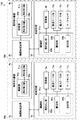
続いて、図3を参照して、画像生成装置2a及び画像形成装置2bの制御に係る構成を説明する。画像形成装置2a及び画像形成装置2bは、端末装置60と、LAN(Local Area Network)等のネットワーク又はUSB(Universal Serial Bus)によって互いに接続されている。
Next, a configuration relating to control of the
画像形成装置2aは、CPU(Central Processing Unit)50aと、LAN通信部51aと、USB通信部52aと、パネル制御部53aと、オペレーションパネル54aと、コマンド解析部55aと、記憶装置制御部56aと、記憶装置57aと、印刷制御部58aと、を備える。
The
CPU50aは、命令やデータを転送するための伝送経路であるシステムバスを介して画像形成装置2aの各部と接続され、画像形成装置2aの各部の動作を制御する。CPU50aは、不図示のROM(Read Only Memory)及びRAM(Random Access Memory)をワークメモリとして用いながら、ROMや記憶装置57aに記憶されているシステムソフトウェア等の各種プログラムを読み出し、適宜実行する。
The CPU 50a is connected to each part of the
LAN通信部51a及びUSB通信部52aは、それぞれLAN及びUSBを介して、端末装置60、給紙装置1a及び巻き取り装置9aを含む外部の機器と通信する。
The LAN communication unit 51a and the
パネル制御部53aは、例えばLCD(Liquid Crystal Display)等の表示パネルと各種の操作ボタンを含む入力装置とを備えるオペレーションパネル54aに接続される。パネル制御部53aは、CPU50aの制御のもと、画像や文字等をオペレーションパネル54aに表示し、オペレーションパネル54aに入力されたユーザからの操作を受け付ける。
The panel control unit 53a is connected to an
コマンド解析部55aは、CPU50aの制御のもと、端末装置60から送信される印刷データに含まれるコマンドの解析を行い、印刷データをビットマップの画像データに変換する。コマンド解析部55aは、変換したビットマップの画像データを、画像形成装置2aが備えるトナーの色ごとに、フレームメモリの対応する記憶エリアに展開する。フレームメモリに展開された画像データは、印刷制御部58aに出力される。
The
記憶装置57aは、例えばEEPROM(Electrically Erasable Programmable ROM)やHDD(Hard Disk Drive)などの不揮発性メモリである。記憶装置制御部56aは、CPU50aの制御のもと、記憶装置57aへのデータの書き込み、及び記憶装置57aに記憶されたデータの読み出しを制御する。
The
印刷制御部58aは、CPU50aの制御のもと、画像形成部20aと中間転写ベルトユニット30aと定着装置40aとを含む印刷機構を制御し、コマンド解析部55aによって生成された画像データに従って印刷処理を行う。
The
画像形成装置2bは、CPU50bと、LAN通信部51bと、USB通信部52bと、パネル制御部53bと、オペレーションパネル54bと、コマンド解析部55bと、記憶装置制御部56bと、記憶装置57bと、印刷制御部58bと、を備える。画像形成装置2bは、画像形成装置2aと同様の制御に係る構成を有するため、詳細な説明を省略する。
The
端末装置60は、例えばPC(Personal Computer)等の情報処理装置であって、LAN及びUSBを介して2つの画像形成装置2a、2bと接続される。端末装置60は、制御部61と、通信部62と、操作部63と、表示部64と、記憶部65と、を備える。
The
制御部61は、例えばCPUと、CPUのメインメモリとして機能するRAM等を備える。制御部61は、命令やデータを転送するための伝送経路であるシステムバスを介して端末装置60の各部と接続され、端末装置60全体を制御する。
The
通信部62は、制御部61の制御のもと、USB又はLANを介して2つの画像形成装置2a、2bと通信する。
The
操作部63は、例えばマウスやキーボード等の入力装置を備える。操作部63は、ユーザからの操作を受け付ける。例えば、操作部63は、ユーザの操作に従って、印刷条件を設定するための信号や、印刷を実行するための信号を制御部61に供給する。
The
表示部64は、例えばCRT(Cathode Ray Tube)やLCD等の表示装置を備える。表示部64は、制御部61から供給される画像データに基づいて画像を画面に表示する。
The
記憶部65は、例えばHDD、ROM、フラッシュメモリ等の記憶装置を備える。記憶部65は、2つの画像形成装置2a、2bを用いて多色印刷するためのプリンタドライバを含む、制御部61が各種処理を行うために使用するプログラム及びデータを記憶する。
The
例として図4(a)に示すように、各ラベルが四角と丸と三角との図形によって構成される複数のラベルの画像データ70を、端末装置60から印刷システム100を用いてロール紙3に印刷する場合について説明する。
As an example, as shown in FIG. 4A,
ユーザが操作部63を操作して、印刷対象の画像データ70の印刷指示を所定のアプリケーションを介して行うと、制御部61は、記憶部65に記憶されたプリンタドライバに従って、通常色印刷システム10a用の画像データと、特別色印刷システム10b用の画像データと、を生成する。
When the user operates the
具体的に説明すると、制御部61は、通常色印刷システム10a用の画像データとして、印刷対象の画像データ70からブラック(K)のトナーで出力すべき画像データを抽出して、例えば図4(b)に示す通常色画像データ71を生成する。なお、カラー印刷が指示された場合には、制御部61は、さらにYMCの各色のトナーで出力すべき画像データを、通常色印刷システム10a用の画像データとして生成する。
More specifically, the
また、制御部61は、図4(c)に示すように、印刷対象の画像データ70に対して画像が上下反転し、且つ、左右反転した(すなわち画像中心を軸として180度回転した)反転データ72を生成する。そして、特別色印刷システム10b用の画像データとして、反転データ72から特別色のトナーで出力すべき画像データを抽出して、例えば図4(d)に示す特別色画像データ73を生成する。なお、複数種類の特別色を用いた印刷が指示された場合には、制御部61は、指示された種類の画像データを、特別色印刷システム10b用の画像データとして生成する。
Further, as shown in FIG. 4C, the
このとき、制御部61は、反転データ72から特別色画像データ73を生成することに限らず、反転処理と抽出処理との順番を逆にしてもよい。すなわち、制御部61は、画像データ70から特別色のトナーで出力すべき画像データを抽出した後で、抽出した画像データの画像を上下反転し、且つ、左右反転することにより、特別色画像データ73を生成してもよい。
At this time, the
制御部61は、生成した通常色画像データ71と印刷条件とを含む第1の印刷データを、通信部62を介して画像形成装置2aに送信する。また、制御部61は、生成した特別色画像データ73と印刷条件とを含む第2の印刷データを、通信部62を介して画像形成装置2bに送信する。なお、印刷条件とは、解像度や階調値のような画像形成に関する設定条件やロール紙3のサイズや種類、印刷距離のような他の印刷設定条件等である。
The
第1及び第2の印刷データが送信されると、給紙装置1a、1b及び巻き取り装置9a、9bが駆動して、印刷が開始する。図5を参照して、給紙装置1a、1b及び巻き取り装置9a、9bの制御に係る構成を説明する。
When the first and second print data are transmitted, the
給紙装置1aが備える制御部81aは、不図示のCPU、RAM、ROM等の機能により、給紙装置1a全体の動作を制御する。具体的には、制御部81aは、巻き出し部82a、搬送部83a、及び検知部84aとして機能する。
The control unit 81a included in the
巻き出し部82aは、第1の巻き出し手段として機能し、保持部8aが保持するロール紙3を巻き出す。例えば図6に示すように、印刷開始前、ユーザは、始端77を固定テープ74で固定された印刷前のロール紙3を、給紙装置1aの筐体から保持部8aを引き出して、保持部8aに取り付ける。この状態において、第1の印刷データを受信した画像形成装置2aから給紙要求を受信すると、巻き出し部82aは、保持部8aの回転軸を回転させて、保持部8aに取り付けられたロール紙3を始端77から順に巻き出す。搬送部83aは、搬送ローラ対13a及び進入ローラ対16a等を駆動させて、巻き出し部82aが巻き出したロール紙3を画像形成装置2aへと順次搬送する。
The unwinding
ロール紙3には、予めオリジナルマーク75が記録される。オリジナルマーク75は、画像形成装置2aがロール紙3に画像形成する際の位置の基準となる第1の基準マークとして機能する。検知部84aは、第1の検知手段として機能し、巻き出し部82aにより巻き出されて搬送部83aにより搬送されるロール紙3に記録されたオリジナルマーク75を、マークセンサ15aにより検知する。
An
例えば図7(a)に示すように、オリジナルマーク75は、ロール紙3の始端77から終端78までの複数の位置に一定間隔で記録される。この間隔は、画像形成装置2aがラベル毎に画像形成の位置を調整できるように、出力すべき画像データ70における各ラベルのピッチに相当する長さに設定される。なお、理解を容易にするため、図7(a)はロール紙3を全て巻き出して広げた状態で示している。また、矢印はロール紙3の搬送方向を表す。これらは後述する図7(b)、図10(a)及び図10(b)でも同様とする。
For example, as shown in FIG. 7A, the
画像形成装置2aは、端末装置60から送信された通常色画像データ71に基づいて、YMCKの4色のトナーによる第1のトナー像を形成し、搬送部83aにより搬送されたロール紙3に第1のトナー像を転写する。このとき、画像形成装置2aは、第1のトナー像を転写する領域が前後及び左右にずれないように、検知部84aが検知したオリジナルマーク75を位置基準として、ロール紙3に第1のトナー像を転写する。その結果、例えば図7(b)に示すような複数のラベルの出力画像がロール紙3に出力される。
Based on the normal
画像形成装置2aは、第1のトナー像に加え、さらに反転マーク76をロール紙3に記録する。反転マーク76は、後続の特別色印刷システム10bにおいて、画像形成装置2bがロール紙3に画像形成する際の位置の基準となる第2の基準マークとして機能する。後述するように、特別色印刷システム10bでは、ロール紙3は通常色印刷システム10aの搬送の向きとは逆向きに搬送されるため、特別色印刷システム10bで画像形成する際の位置基準として、オリジナルマーク75を再利用することは難しい。そのため、画像形成装置2aは、オリジナルマーク75とは別の基準として反転マーク76をロール紙3に記録する。
The
より詳細に説明すると、画像形成装置2aは、第1のトナー像を転写した領域の後端部を含むロール紙3の搬送方向に沿った複数の位置に、反転マーク76を記録する。例えば図7(b)に示すように、画像形成装置2aは、オリジナルマーク75の近傍にオリジナルマーク75が記録された間隔と同じ間隔で反転マーク76を記録し、さらにオリジナルマーク75が記録されていないロール紙3の終端78付近(第1のトナー像を転写した領域の後端部)にも反転マーク76を記録する。このような最も終端78に近い位置に記録された反転マーク76は、後続の特別色印刷システム10bにおいて画像形成を開始するための基準となる。第1のトナー像及び反転マーク76が記録されたロール紙3は、定着装置40aで定着されて、巻き取り装置9aへと排出される。
More specifically, the
巻き取り装置9aが備える制御部95aは、不図示のCPU、RAM、ROM等の機能により、巻き取り装置9a全体の動作を制御する。具体的には、制御部95aは、巻き取り部96aとして機能し、画像形成装置2aが通常色画像データ71に基づく第1のトナー像を転写したロール紙3を、ロール紙3の始端77から終端78への順に、巻き取り軸91aの周りに巻き取る。
The
例えば図8(a)に示すように、巻き取り部96aは、画像形成装置2aからロール紙3の巻き取り要求を受信すると、巻き取り軸91aを回転させて、画像形成装置2aから排出されるロール紙3を、始端77から順に巻き取り始める。そして、図8(b)に示すように、巻き取り部96aは、画像形成装置2aから排出されるロール紙3を、終端78まで巻き取る。巻き取りが終了すると、通常色印刷システム10aにおける印刷は終了する。巻き取り終わったロール紙3の終端78は、固定テープ74により仮固定される。
For example, as shown in FIG. 8A, when the take-up
巻き取り装置9aが巻き取ったロール紙3は、さらに特別色による追加印刷を行うため、図9(a)に示すように巻き取り装置9aから取り外され、特別色印刷システム10bの給紙装置1bの保持部8bに取り付けられる。このとき、ユーザは、保持部8bから巻き出したロール紙3の第1のトナー像を転写した面に新たに特別色のトナー像を転写できるように、ロール紙3を通常色印刷システム10aの給紙装置1aに取り付けたときと比べてロール紙3の奥と手前とを逆にして、給紙装置1bが備える保持部8bに取り付ける。具体的には図9(b)に示すように、反転マーク76がオリジナルマーク75の奥に位置していたロール紙3を、反転マーク76がオリジナルマーク75の手前に位置するように、奥と手前とを入れ替える。
The
すなわち、巻き取り装置9aに巻き取られた後のロール紙3は始端77が内側にあり終端78が外側にあるため、通常色印刷システム10aの給紙装置1aに取り付けられたロール紙3と比べて、特別色印刷システム10bの給紙装置1bに取り付けられたロール紙3は、左右(奥と手前)が反転し、且つ、前後(前端と後端)が反転した状態にある。
That is, the
ここで図5に戻って、特別色印刷システム10bの制御に係る構成について説明する。給紙装置1bが備える制御部81bは、不図示のCPU、RAM、ROM等の機能により、給紙装置1b全体の動作を制御する。具体的には、制御部81bは、巻き出し部82b、搬送部83b、及び検知部84bとして機能する。
Now, referring back to FIG. 5, the configuration relating to the control of the special
巻き出し部82bは、第2の巻き出し手段として機能し、保持部8bの回転軸を回転させて、保持部8bに取り付けられたロール紙3を、ロール紙3の終端78から始端77への順に巻き出す。搬送部83bは、搬送ローラ対13b及び進入ローラ対16b等を駆動させて、巻き出し部82bが巻き出したロール紙3を画像形成装置2bへと順次搬送する。具体的には図10(a)に示すように、搬送部83bは、通常色印刷システム10aにおいて第1のトナー像が転写されたロール紙3を、終端78を先頭にして搬送する。
The unwinding
検知部84bは、第2の検知手段として機能し、巻き出し部82bにより巻き出されて搬送部83bにより搬送されるロール紙3に記録された反転マーク76を、マークセンサ15bにより検知する。
The
画像形成装置2bは、印刷対象の画像データ70に対して画像が上下反転し、且つ、左右反転した画像データである特別色画像データ73に基づいて、YMCKに含まれない特別色のトナーによる第2のトナー像を形成する。具体的に説明すると、画像形成装置2bは、白色のトナーによる画像を形成する2つの画像形成ユニット21w1、21w2により2つの白色トナー像を形成し、他の特別色による画像を形成する2つの画像形成ユニット21s1、21s2により他の特別色のトナー像を形成する。そして、形成した2つの白色トナー像と他の特別色のトナー像とを重ねることにより、第2のトナー像を形成する。そして、搬送部83bにより搬送されたロール紙3の第1のトナー像が転写された領域に、第2のトナー像を転写する。
Based on the special
このとき、画像形成装置2bは、第2のトナー像を転写する領域が前後及び左右にずれないように、検知部84bが検知した反転マーク76を位置基準として、ロール紙3に第2のトナー像を転写する。その結果、図10(b)に示すように、印刷対象の画像データ70を再現した複数のラベルの出力画像がロール紙3に出力される。第2のトナー像が転写されたロール紙3は、定着装置40bで定着されて、巻き取り装置9bへと排出される。
At this time, the
巻き取り装置9bが備える制御部95bは、不図示のCPU、RAM、ROM等の機能により、巻き取り装置9b全体の動作を制御する。具体的には、制御部95bは、巻き取り部96bとして機能し、画像形成装置2bが特別色画像データ73に基づく第2のトナー像を転写したロール紙3を、ロール紙3の終端78から始端77への順に、巻き取り軸91bの周りに巻き取る。その結果、所望の多色印刷がされたロール紙3を、印刷開始前と同様に、始端77を外側且つ終端78を内側にして巻き取った状態で得ることができる。
The
以上のような印刷システム100の多色印刷処理の流れについて、図11及び図12に示すフローチャートを参照して説明する。
The flow of the multicolor printing process of the
印刷システム100の多色印刷処理は、図6に示したように、通常色印刷システム10aにおける給紙装置1aに印刷前のロール紙3が取り付けられ、印刷準備が完了した状態において、開始する。
As shown in FIG. 6, the multicolor printing process of the
端末装置60において、制御部61が、例えば操作部63を介してユーザから印刷指示を受け付けると(ステップS1)、図11に示すフローチャートにおける処理が開始する。
In the
印刷指示を受け付けると、制御部61は、印刷指示に従って第1の印刷データを生成し、生成した第1の印刷データを通常色印刷システム10aの画像形成装置2aに送信する(ステップS2)。第1の印刷データは、例えば図4(b)に示した通常色画像データ71のように、印刷対象の画像データ70中のYMCKの4色で出力すべき画像データ、及び印刷条件を含む。
When receiving the print instruction, the
第1の印刷データの生成及び送信と共に、制御部61は、印刷指示に従って第2の印刷データを生成し、生成した第2の印刷データを特別色印刷システム10bの画像形成装置2bに送信する(ステップS3)。第2の印刷データは、例えば図4(d)に示した特別色画像データ73のように、印刷対象の画像データ70中のYMCK以外の特別色で出力すべき画像データであって、印刷対象の画像データ70に対して画像が上下反転し、且つ、左右反転した画像データ、及び印刷条件を含む。
Along with the generation and transmission of the first print data, the
通常色印刷システム10aにおいて、画像形成装置2aは、端末装置60から送信された第1の印刷データを、LAN通信部51a又はUSB通信部52aを介して受信する(ステップS11)。特別色印刷システム10bにおいて、画像形成装置2bは、端末装置60から送信された第2の印刷データを、LAN通信部51b又はUSB通信部52bを介して受信する(ステップS21)。以降の処理は、図12に示すフローチャートを参照して説明する。
In the normal
通常色印刷システム10aにおいて、画像形成装置2aは、端末装置60から第1の印刷データを受信すると、給紙装置1aに給紙要求を送信し、巻き取り装置9aに巻き取り要求を送信して、ロール紙3の巻き出し、搬送、及び巻き取りを開始する(ステップS12)。給紙要求を受信した給紙装置1aでは、巻き出し部82aが、保持部8aが保持するロール紙3を、始端77から終端78への順に巻き出して、搬送部83aによる搬送を経由して画像形成装置2aに供給する。
In the normal
ロール紙3の巻き出し及び搬送が開始されると、検知部84aは、搬送されるロール紙3に予め記録されたオリジナルマーク75を検知する(ステップS13)。そして、画像形成装置2aは、検知したオリジナルマーク75の位置を基準として、搬送されたロール紙3に、通常色(YMCK)による画像形成を行う(ステップS14)。また、画像形成装置2aは、画像形成と同時に、ロール紙3に反転マーク76を記録する(ステップS15)。巻き取り要求を受信した巻き取り装置9aでは、巻き取り部96aが、画像形成され、反転マーク76が記録されたロール紙3を順次巻き取る。
When unwinding and conveyance of the
このように画像形成しながら、画像形成装置2aは、指示された画像形成が終了したか否かを判別する(ステップS16)。指示された画像形成が終了していない場合(ステップS16;NO)、処理はステップS13に戻る。すなわち、通常色印刷システム10aは、指示された画像形成が終了するまで、ステップS13〜S15の処理を繰り返して、画像形成を続ける。
While forming an image in this way, the
指示された画像形成が終了すると(ステップS16;YES)、画像形成装置2aは、給紙装置1aに給紙停止要求を送信し、巻き取り装置9aに巻き取り停止要求を送信して、ロール紙3の巻き出し、搬送、及び巻き取りを停止させる(ステップS17)。そして、通常色印刷システム10aにおける印刷は終了する。
When the instructed image formation is completed (step S16; YES), the
通常色印刷システム10aにおける印刷が終了すると、巻き取り装置9aに巻き取られたロール紙3は、図9(a)及び図9(b)に示したように巻き取り装置9aから取り外されて、特別色印刷システム10bの給紙装置1bに向きを変えて取り付けられる。このような印刷準備が完了し、ユーザが特別色での印刷指示を例えば画像形成装置2bのオペレーションパネル54bを介して入力すると、特別色印刷システム10bにおける印刷が開始する。
When printing in the normal
すなわち、通常色印刷システム10aが通常色(YMCK)による印刷をしている間、特別色印刷システム10bにおいて端末装置60から第2の印刷データを受信した画像形成装置2bは、印刷開始を指示されたか否かを判別し(ステップS22)、印刷開始が指示されない間は(ステップS22;NO)待機している。
That is, while the normal
印刷開始を指示されると(ステップS22;YES)、画像形成装置2bは、給紙装置1bに給紙要求を送信し、巻き取り装置9bに巻き取り要求を送信して、ロール紙3の巻き出し、搬送、及び巻き取りを開始する(ステップS23)。給紙要求を受信した給紙装置1bでは、巻き出し部82bが、保持部8bが保持するロール紙3を、終端78から始端77への順に巻き出して、搬送部83bによる搬送を経由して画像形成装置2bに供給する。
When instructed to start printing (step S22; YES), the
ロール紙3の巻き出し及び搬送が開始されると、検知部84bは、搬送されるロール紙3に記録された反転マーク76を検知する(ステップS24)。そして、画像形成装置2bは、検知した反転マーク76の位置を基準として、搬送されたロール紙3に、特別色による画像形成を行う(ステップS25)。巻き取り要求を受信した巻き取り装置9bでは、巻き取り部96bが、画像形成されたロール紙3を順次巻き取る。
When unwinding and conveyance of the
このように画像形成しながら、画像形成装置2bは、指示された画像形成が終了したか否かを判別する(ステップS26)。指示された画像形成が終了していない場合(ステップS26;NO)、処理はステップS24に戻る。すなわち、特別色印刷システム10bは、指示された画像形成が終了するまで、ステップS24〜S25の処理を繰り返して、画像形成を続ける。
While forming an image in this way, the
指示された画像形成が終了すると(ステップS26;YES)、画像形成装置2bは、給紙装置1bに給紙停止要求を送信し、巻き取り装置9bに巻き取り停止要求を送信して、ロール紙3の巻き出し、搬送、及び巻き取りを停止させる(ステップS27)。そして、特別色印刷システム10b及び印刷システム100における印刷は終了する。
When the instructed image formation is completed (step S26; YES), the
以上説明したように、実施形態1に係る印刷システム100は、4色のカラー印刷に対応した2つの画像形成装置2a、2bを用いて順次画像形成することにより、最大で8色のトナーによる多色印刷を実現する。一般的なYMCKの4色に加えて他色の現像剤での印刷が可能であるため、例えば白色のトナーによる画像を形成する2つの画像形成ユニット21w1、21w2により、白色のトナー像を2層重ねて転写することができ、濃いベース部分に白色のトナー像を転写する場合でも十分な白色度を得ることができる。また、同等のハードウェア構成を有する4色のカラー印刷に対応した画像形成装置を2つ用意すればよいため、5色以上のカラー印刷に対応した大型な専用装置を用意する必要がない。
As described above, the
また、実施形態1に係る印刷システム100は、第1の画像形成装置2aにおける画像形成後、定着装置40aによる定着が既に完了したロール紙3に対して、第2の画像形成装置2bで画像形成する。そのため、定着装置が定着すべき現像剤の層厚が厚くなりすぎることがなく、定着精度の悪化を防ぐことができる。
In addition, the
さらには、実施形態1に係る印刷システム100は、第1の画像形成装置2aにおける画像形成及び定着後のロール紙3を一旦巻き取り装置9aで巻き取り、第2の給紙装置1bに取り付けてから、ロール紙3に対して第2の画像形成装置2bで画像形成する。すなわち、第1の画像形成装置2aにおける定着によりロール紙3に付与された熱が十分に冷めた状態で、第2の画像形成装置2bが画像形成を開始する。そのため、実施形態1に係る印刷システム100は、例えば第1の画像形成装置2aの上に第2の画像形成装置2bを据え置いて、第1の画像形成装置2aによる画像形成及び定着後すぐに第2の画像形成装置2bで画像形成するような構成に比べて、高い印刷品質を確保できる。
Furthermore, in the
(実施形態2)
以下、本発明の実施形態2に係る印刷システムについて説明する。
(Embodiment 2)
Hereinafter, a printing system according to
図13に、実施形態2に係る印刷システムの構成を示す。印刷システム101は、YMCKの4色の現像剤を用いて画像形成する画像形成装置2aと、YMCK以外の特別色の現像剤を用いて画像形成する画像形成装置2bと、給紙装置1aと、巻き取り装置9aと、を備える。すなわち、上記実施形態1に係る印刷システム100は、2つの給紙装置1a、1bと、2つの巻き取り装置9a、9bと、を備えていた。これに対し、実施形態2に係る印刷システム101は、第2の給紙装置1bと第2の巻き取り装置9bとを備えない。
FIG. 13 shows a configuration of a printing system according to the second embodiment. The
通常色(YMCKの4色)による第1の画像形成の際には、図13に示すように、第1の画像形成手段として機能する画像形成装置2aが、給紙装置1aの上に据え置かれる。そして、給紙装置1aと画像形成装置2aと巻き取り装置9aとが、実施形態1における通常色印刷システム10aに相当するシステムを構成する。
At the time of the first image formation with the normal colors (four colors of YMCK), as shown in FIG. 13, the
一方、特別色(白色等)による第2の画像形成の際には、図14に示すように、第2の画像形成手段として機能する画像形成装置2bが、画像形成装置2aと入れ替えられて、給紙装置1aの上に据え置かれる。そして、給紙装置1aと画像形成装置2bと巻き取り装置9aとが、実施形態1における特別色印刷システム10bに相当するシステムを構成する。
On the other hand, when the second image is formed with a special color (white or the like), as shown in FIG. 14, the
すなわち、実施形態2における給紙装置1aは、実施形態1における2つの給紙装置1a、1bのいずれとしても機能する。例えば、給紙装置1aが備える保持部8aは、第1の画像形成手段として機能する画像形成装置2aにより画像形成される前のロール紙3を保持し、且つ、画像形成装置2aにより画像形成され、巻き取り装置9aにより巻き取られた後のロール紙3をさらに保持する保持手段として機能する。巻き出し部82aは、保持部8aが保持するロール紙3を始端77から終端78への順に巻き出して、画像形成装置1aに供給する第1の巻き出し手段として機能し、且つ、保持部8aが保持するロール紙3を終端78から始端77への順に巻き出して、画像形成装置1bに供給する第2の巻き出し手段として機能する。検知部84aは、予めロール紙3に記録されたオリジナルマーク75を検知する第1の検知手段として機能し、且つ、第1の画像形成の際にロール紙3に記録された反転マーク76を検知する第2の検知手段として機能する。
That is, the
同様に、実施形態2における巻き取り装置9aは、実施形態1における2つの巻き取り装置9a、9bのいずれとしても機能する。例えば、巻き取り部96aは、画像形成装置1aが画像形成したロール紙3を、始端77から終端78への順に巻き取り、且つ、画像形成装置1bが画像形成したロール紙3を、終端78から始端77への順に巻き取る。
Similarly, the winding
このような構成により、実施形態2に係る印刷システム101は、実施形態1に係る印刷システム100に比べて、少ない構成要素で同等に高品質な多色印刷を実行することができる。
With such a configuration, the
(実施形態3)
以下、本発明の実施形態3に係る印刷システムについて説明する。
(Embodiment 3)
Hereinafter, a printing system according to
図15に、実施形態3に係る印刷システムの構成を示す。印刷システム102は、YMCKの4色の現像剤を用いて画像形成する画像形成装置2aと、YMCK以外の特別色の現像剤を用いて画像形成するための画像形成部20b及び中間転写ベルトユニット30bと、給紙装置1aと、巻き取り装置9aと、を備える。すなわち、上記実施形態2に係る印刷システム101は、2つの画像形成装置2a、2bを備えていた。これに対し、実施形態3に係る印刷システム102は、第2の画像形成装置2bを備えない。
FIG. 15 shows the configuration of a printing system according to the third embodiment. The
通常色(YMCKの4色)による第1の画像形成の際には、図15に示すように、YMCKの4色の画像形成ユニット21y、21m、21c、21kを含む画像形成部20a及び中間転写ベルトユニット30aを備えた画像形成装置2aが、第1の画像形成手段として機能する。
When the first image is formed with normal colors (four colors of YMCK), as shown in FIG. 15, the
一方、特別色(白色等)による第2の画像形成の際には、図16に示すように、画像形成装置2a内の画像形成部20a及び中間転写ベルトユニット30aを、それぞれ特別色の画像形成ユニット21w1、21w2、21s1、21s2を含む画像形成部20b及び中間転写ベルトユニット30bに入れ替える。そして、画像形成部20b及び中間転写ベルトユニット30bを備えた画像形成装置2aが、第2の画像形成手段として機能する。
On the other hand, when the second image is formed with a special color (white or the like), as shown in FIG. 16, the
すなわち、実施形態3に係る印刷システム102では、1台の画像形成装置2aが、画像形成ユニット21を含む構成要素を着脱可能に格納し、第1の画像形成手段と第2の画像形成手段とのいずれとしても機能する。その結果、実施形態3に係る印刷システム102は、実施形態2に係る印刷システム101に比べて、さらに少ない構成要素で同等に高品質な多色印刷を実行することができる。
That is, in the
(変形例)
以上に本発明の実施形態について説明したが、上記実施形態は一例であり、本発明の適用範囲はこれに限られない。すなわち、本発明の実施形態は種々の応用が可能であり、あらゆる実施の形態が本発明の範囲に含まれる。
(Modification)
Although the embodiment of the present invention has been described above, the above embodiment is an example, and the scope of application of the present invention is not limited to this. That is, the embodiments of the present invention can be applied in various ways, and all the embodiments are included in the scope of the present invention.
例えば、上記実施形態では、第1の画像形成手段として機能する画像形成装置1aが通常色(YMCKの4色)の現像剤を用いて画像形成し、第2の画像形成手段として機能する画像形成装置1bが特別色(白色を含むYMCK以外の色)の現像剤を用いて画像形成した。しかし、第1の画像形成手段と第2の画像形成手段とにおける現像剤の色の組合せはこれに限らず、どのような組合せであってもよい。
For example, in the above-described embodiment, the
また、上記実施形態では、ロール紙3には、第1の基準マークとして予めオリジナルマーク75が記録された。しかし、本発明に係る印刷システムは、他の位置基準を用いて第1のトナー像をロール紙3に転写することができるのであれば、オリジナルマーク75が記録されていないロール紙3を用いることができる。
In the above embodiment, the
また、上記実施形態では、印刷システム100、101、102は、ロール紙3に多色印刷を実行した。しかし、本発明に係る印刷システムは、ロール紙3すなわち紙媒体に限らず、フィルム状の記録媒体等、その他の材質のロール状記録媒体に多色印刷を実行してもよい。
In the above-described embodiment, the
なお、本発明に係る機能を実現するための構成を予め備えた印刷システムとして提供できることはもとより、プログラムの適用により、既存の情報処理装置等を、本発明に係る印刷システムとして機能させることもできる。すなわち、上記実施形態で例示した印刷システム100、101、102による各機能構成を実現させるためのプログラムを、既存の情報処理装置等を制御するCPU等が実行できるように適用することで、本発明に係る印刷システムとして機能させることができる。また、本発明に係る印刷方法は、印刷システムを用いて実施できる。
In addition, not only can a configuration for realizing the functions according to the present invention be provided in advance, but also an existing information processing apparatus or the like can be caused to function as the printing system according to the present invention by applying a program. . That is, by applying the program for realizing each functional configuration by the
また、このようなプログラムの適用方法は任意である。プログラムを、例えば、フレキシブルディスク、CD(Compact Disc)−ROM、DVD(Digital Versatile Disc)−ROM、メモリカード等のコンピュータ読み取り可能な記憶媒体に格納して適用できる。さらに、プログラムを搬送波に重畳し、インターネットなどの通信媒体を介して適用することもできる。例えば、通信ネットワーク上の掲示板(BBS:Bulletin Board System)にプログラムを掲示して配信してもよい。そして、このプログラムを起動し、OS(Operating System)の制御下で、他のアプリケーションプログラムと同様に実行することにより、上記の処理を実行できるように構成してもよい。 Moreover, the application method of such a program is arbitrary. The program can be applied by being stored in a computer-readable storage medium such as a flexible disk, a CD (Compact Disc) -ROM, a DVD (Digital Versatile Disc) -ROM, or a memory card. Furthermore, the program can be superimposed on a carrier wave and applied via a communication medium such as the Internet. For example, the program may be posted on a bulletin board (BBS: Bulletin Board System) on a communication network and distributed. The program may be started and executed in the same manner as other application programs under the control of an OS (Operating System) so that the above-described processing can be executed.
以上、本発明の好ましい実施形態について説明したが、本発明は係る特定の実施形態に限定されるものではなく、本発明には、特許請求の範囲に記載された発明とその均等の範囲とが含まれる。以下に、本願出願の当初の特許請求の範囲に記載された発明を付記する。 The preferred embodiments of the present invention have been described above. However, the present invention is not limited to the specific embodiments, and the present invention includes the invention described in the claims and the equivalent scope thereof. included. Hereinafter, the invention described in the scope of claims of the present application will be appended.
(付記1)
第1の巻き出し手段により巻き出されたロール状記録媒体に、画像データに基づいて第1の現像剤像を転写する第1の画像形成手段と、
前記第1の画像形成手段が前記第1の現像剤像を転写した前記ロール状記録媒体を、前記ロール状記録媒体の始端から終端への順に、巻き取り軸の周りに巻き取る第1の巻き取り手段と、
前記第1の巻き取り手段が前記巻き取り軸の周りに巻き取った前記ロール状記録媒体を、前記ロール状記録媒体の前記終端から前記始端への順に、巻き出す第2の巻き出し手段と、
前記第2の巻き出し手段により巻き出された前記ロール状記録媒体の前記第1の現像剤像が転写された領域に、画像が上下反転し、且つ、左右反転した画像データに基づいて第2の現像剤像を転写する第2の画像形成手段と、
を備える、
ことを特徴とする印刷システム。
(Appendix 1)
A first image forming means for transferring a first developer image based on the image data to a roll-shaped recording medium unwound by the first unwinding means;
A first winding for winding the roll-shaped recording medium onto which the first developer image has been transferred by the first image forming unit around a winding shaft in order from the start end to the end of the roll-shaped recording medium. Taking means,
A second unwinding means for unwinding the roll-shaped recording medium wound around the winding shaft by the first winding means in order from the end to the starting end of the roll-shaped recording medium;
The image is inverted upside down in the area where the first developer image of the roll-shaped recording medium unwound by the second unwinding means is transferred, and second on the basis of the image data which is horizontally reversed. A second image forming means for transferring the developer image of
Comprising
A printing system characterized by that.
(付記2)
前記第1の画像形成手段は、複数色の現像剤による前記第1の現像剤像を形成し、
前記第2の画像形成手段は、前記複数色に含まれない色を含む1色以上の現像剤による前記第2の現像剤像を形成する、
ことを特徴とする付記1に記載の印刷システム。
(Appendix 2)
The first image forming means forms the first developer image with a plurality of color developers,
The second image forming unit forms the second developer image with one or more developers including colors not included in the plurality of colors;
The printing system according to
(付記3)
前記ロール状記録媒体には、予め第1の基準マークが記録され、
前記第1の巻き出し手段により巻き出された前記ロール状記録媒体に記録された前記第1の基準マークを検知する第1の検知手段をさらに備え、
前記第1の画像形成手段は、前記第1の検知手段が検知した前記第1の基準マークを位置基準として、前記ロール状記録媒体に前記第1の現像剤像を転写する、
ことを特徴とする付記1又は2に記載の印刷システム。
(Appendix 3)
A first reference mark is recorded in advance on the roll-shaped recording medium,
A first detection means for detecting the first reference mark recorded on the roll-shaped recording medium unwound by the first unwinding means;
The first image forming unit transfers the first developer image to the roll-shaped recording medium using the first reference mark detected by the first detection unit as a position reference.
The printing system according to
(付記4)
前記第1の画像形成手段は、前記第1の巻き出し手段により巻き出された前記ロール状記録媒体に第2の基準マークを記録し、
前記第2の巻き出し手段により巻き出された前記ロール状記録媒体に記録された前記第2の基準マークを検知する第2の検知手段をさらに備え、
前記第2の画像形成手段は、前記第2の検知手段が検知した前記第2の基準マークを位置基準として、前記ロール状記録媒体の前記第1の現像剤像が転写された前記領域に、前記第2の現像剤像を転写する、
ことを特徴とする付記1乃至3のいずれか1つに記載の印刷システム。
(Appendix 4)
The first image forming unit records a second reference mark on the roll-shaped recording medium unwound by the first unwinding unit;
A second detection means for detecting the second reference mark recorded on the roll-shaped recording medium unwound by the second unwinding means;
The second image forming unit uses the second reference mark detected by the second detection unit as a position reference, and the region where the first developer image of the roll-shaped recording medium is transferred to the region. Transferring the second developer image;
The printing system according to any one of
(付記5)
前記第1の画像形成手段は、前記第1の現像剤像を転写した前記領域の後端部を含む前記ロール状記録媒体の搬送方向に沿った複数の位置に、前記第2の基準マークを記録する、
ことを特徴とする付記4に記載の印刷システム。
(Appendix 5)
The first image forming means places the second reference marks at a plurality of positions along the conveyance direction of the roll-shaped recording medium including the rear end portion of the area where the first developer image is transferred. Record,
The printing system according to appendix 4, characterized in that:
(付記6)
前記第1の画像形成手段により前記第1の現像剤像が転写される前の前記ロール状記録媒体を保持する第1の保持手段と、
前記第1の画像形成手段により前記第1の現像剤像が転写され、前記第1の巻き取り手段により巻き取られた後の前記ロール状記録媒体を保持する第2の保持手段と、
をさらに備え、
前記第1の巻き出し手段は、前記第1の保持手段が保持する前記ロール状記録媒体を、前記ロール状記録媒体の前記始端から前記終端への順に巻き出して、前記第1の画像形成手段に供給し、
前記第2の巻き出し手段は、前記第2の保持手段が保持する前記ロール状記録媒体を、前記ロール状記録媒体の前記終端から前記始端への順に巻き出して、前記第2の画像形成手段に供給する、
ことを特徴とする付記1乃至5のいずれか1つに記載の印刷システム。
(Appendix 6)
First holding means for holding the roll-shaped recording medium before the first developer image is transferred by the first image forming means;
A second holding unit that holds the roll-shaped recording medium after the first developer image is transferred by the first image forming unit and wound by the first winding unit;
Further comprising
The first unwinding unit unwinds the roll-shaped recording medium held by the first holding unit in order from the start end to the end of the roll-shaped recording medium, and the first image forming unit To supply
The second unwinding unit unwinds the roll-shaped recording medium held by the second holding unit in order from the end of the roll-shaped recording medium to the start end, and the second image forming unit. To supply,
The printing system according to any one of
(付記7)
前記第1の画像形成手段により前記第1の現像剤像が転写される前の前記ロール状記録媒体を保持する保持手段をさらに備え、
前記第1の巻き出し手段は、前記保持手段が保持する前記ロール状記録媒体を、前記ロール状記録媒体の前記始端から前記終端への順に巻き出して、前記第1の画像形成手段に供給し、
前記保持手段は、前記第1の画像形成手段により前記第1の現像剤像が転写され、前記第1の巻き取り手段により巻き取られた後の前記ロール状記録媒体をさらに保持し、
前記第2の巻き出し手段は、前記保持手段が保持する前記ロール状記録媒体を、前記ロール状記録媒体の前記終端から前記始端への順に巻き出して、前記第2の画像形成手段に供給する、
ことを特徴とする付記1乃至5のいずれか1つに記載の印刷システム。
(Appendix 7)
A holding unit that holds the roll-shaped recording medium before the first developer image is transferred by the first image forming unit;
The first unwinding unit unwinds the roll-shaped recording medium held by the holding unit in order from the start end to the end of the roll-shaped recording medium, and supplies the unrolled recording medium to the first image forming unit. ,
The holding means further holds the roll-shaped recording medium after the first developer image is transferred by the first image forming means and wound by the first winding means,
The second unwinding unit unwinds the roll-shaped recording medium held by the holding unit in order from the end to the starting end of the roll-shaped recording medium and supplies the unrolled recording medium to the second image forming unit. ,
The printing system according to any one of
(付記8)
前記複数色の現像剤は、イエロー、マゼンダ、シアン、及びブラックの現像剤を含み、
前記1色以上の現像剤は、前記複数色に含まれない色として、白色、金色、銀色、透明色、及び、蛍光又は光沢を与えるための特殊色の少なくともいずれか1色の現像剤を含む、
ことを特徴とする付記2に記載の印刷システム。
(Appendix 8)
The multi-color developers include yellow, magenta, cyan, and black developers,
The developer of one or more colors includes at least one of white, gold, silver, transparent, and a special color for giving fluorescence or gloss as a color not included in the plurality of colors. ,
The printing system according to
(付記9)
前記1色以上の現像剤は、前記複数色に含まれない色として、前記白色の現像剤を含み、
前記第2の画像形成手段は、画像が上下反転し、且つ、左右反転した前記画像データに基づいて、前記白色の現像剤による2つの白色現像剤像を形成し、形成した2つの当該白色現像剤像を重ねることにより前記第2の現像剤像を形成する、
ことを特徴とする付記8に記載の印刷システム。
(Appendix 9)
The one or more color developers include the white developer as a color not included in the plurality of colors,
The second image forming means forms two white developer images with the white developer on the basis of the image data in which the image is inverted upside down and horizontally inverted, and the two white developments formed are formed. Forming the second developer image by overlapping the agent images;
Item 9. The printing system according to
(付記10)
巻き出されたロール状記録媒体に、画像データに基づいて第1の現像剤像を転写し、
前記第1の現像剤像を転写した前記ロール状記録媒体を、前記ロール状記録媒体の始端から終端への順に、巻き取り軸の周りに巻き取り、
前記巻き取り軸の周りに巻き取った前記ロール状記録媒体を、前記ロール状記録媒体の前記終端から前記始端への順に、巻き出し、
巻き出された前記ロール状記録媒体の前記第1の現像剤像が転写された領域に、画像が上下反転し、且つ、左右反転した画像データに基づいて第2の現像剤像を転写する、
ことを特徴とする印刷方法。
(Appendix 10)
The first developer image is transferred to the unrolled roll-shaped recording medium based on the image data,
The roll-shaped recording medium to which the first developer image has been transferred is wound around a winding shaft in order from the start end to the end of the roll-shaped recording medium,
The roll-shaped recording medium wound around the winding shaft is unwound in order from the end to the start end of the roll-shaped recording medium,
The image is inverted upside down and transferred to the second developer image on the basis of the image data obtained by reversing the left and right sides of the rolled recording medium on which the first developer image is transferred.
A printing method characterized by the above.
(付記11)
コンピュータに、
巻き出されたロール状記録媒体に、画像データに基づいて第1の現像剤像を転写させ、
前記第1の現像剤像を転写させた前記ロール状記録媒体を、前記ロール状記録媒体の始端から終端への順に、巻き取り軸の周りに巻き取らせ、
前記巻き取り軸の周りに巻き取らせた前記ロール状記録媒体を、前記ロール状記録媒体の前記終端から前記始端への順に、巻き出させ、
巻き出された前記ロール状記録媒体の前記第1の現像剤像が転写された領域に、画像が上下反転し、且つ、左右反転した画像データに基づいて第2の現像剤像を転写させる、
ことを特徴とするプログラム。
(Appendix 11)
On the computer,
The first developer image is transferred to the unrolled roll-shaped recording medium based on the image data,
The roll-shaped recording medium to which the first developer image is transferred is wound around a winding shaft in order from the start end to the end of the roll-shaped recording medium,
The rolled recording medium wound around the winding shaft is unwound in order from the end to the starting end of the rolled recording medium,
The image is inverted upside down and transferred to the second developer image on the basis of the image data inverted in the left and right direction in the area where the first developer image of the rolled recording medium is transferred.
A program characterized by that.
1a、1b…給紙装置、2a、2b…画像形成装置、3…ロール紙、7a、7b…スライド台、8a、8b…保持部、9a、9b…巻き取り装置、10a…通常色印刷システム、10b…特別色印刷システム、11a、11b…斜行検知センサ、12a、12b…サイドガイド、13a、13b…搬送ローラ対、14a、14b…オートカッタ、15a、15b…マークセンサ、16a、16b…進入ローラ対、17a、17b…進入センサ、20a、20b…画像形成部、21(21y、21m、21c、21k、21w1、21w2、21s1、21s2)…画像形成ユニット、22…感光体ドラム、23…クリーナ、24…帯電ローラ、25…光書込ヘッド、26…現像器、27…現像ローラ、30a、30b…中間転写ベルトユニット、31…転写ベルト、32…駆動ローラ、33…従動ローラ、34…一次転写ローラ、35…待機搬送ローラ対、36…二次転写ローラ、40a、40b…定着装置、41…ヒータ、42…加熱ローラ、43…加圧ローラ、44…排紙ローラ対、50a、50b…CPU、51a、51b…LAN通信部、52a、52b…USB通信部、53a、53b…パネル制御部、54a、54b…オペレーションパネル、55a、55b…コマンド解析部、56a、56b…記憶装置制御部、57a、57b…記憶装置、58a、58b…印刷制御部、60…端末装置、61…制御部、62…通信部、63…操作部、64…表示部、65…記憶部、70…画像データ、71…通常色画像データ、72…反転データ、73…特別色画像データ、74…固定テープ、75…オリジナルマーク、76…反転マーク、77…始端、78…終端、81a、81b…制御部、82a、82b…巻き出し部、83a、83b…搬送部、84a、84b…検知部、91a、91b…巻き取り軸、95a、95b…制御部、96a、96b…巻き取り部、100、101、102…印刷システム
DESCRIPTION OF
Claims (11)
前記第1の画像形成手段が前記第1の現像剤像を転写した前記ロール状記録媒体を、前記ロール状記録媒体の始端から終端への順に、巻き取り軸の周りに巻き取る第1の巻き取り手段と、
前記第1の巻き取り手段が前記巻き取り軸の周りに巻き取った前記ロール状記録媒体を、前記ロール状記録媒体の前記終端から前記始端への順に、巻き出す第2の巻き出し手段と、
前記第2の巻き出し手段により巻き出された前記ロール状記録媒体の前記第1の現像剤像が転写された領域に、画像が上下反転し、且つ、左右反転した画像データに基づいて第2の現像剤像を転写する第2の画像形成手段と、
を備える、
ことを特徴とする印刷システム。 A first image forming means for transferring a first developer image based on the image data to a roll-shaped recording medium unwound by the first unwinding means;
A first winding for winding the roll-shaped recording medium onto which the first developer image has been transferred by the first image forming unit around a winding shaft in order from the start end to the end of the roll-shaped recording medium. Taking means,
A second unwinding means for unwinding the roll-shaped recording medium wound around the winding shaft by the first winding means in order from the end to the starting end of the roll-shaped recording medium;
The image is inverted upside down in the area where the first developer image of the roll-shaped recording medium unwound by the second unwinding means is transferred, and second on the basis of the image data which is horizontally reversed. A second image forming means for transferring the developer image of
Comprising
A printing system characterized by that.
前記第2の画像形成手段は、前記複数色に含まれない色を含む1色以上の現像剤による前記第2の現像剤像を形成する、
ことを特徴とする請求項1に記載の印刷システム。 The first image forming means forms the first developer image with a plurality of color developers,
The second image forming unit forms the second developer image with one or more developers including colors not included in the plurality of colors;
The printing system according to claim 1.
前記第1の巻き出し手段により巻き出された前記ロール状記録媒体に記録された前記第1の基準マークを検知する第1の検知手段をさらに備え、
前記第1の画像形成手段は、前記第1の検知手段が検知した前記第1の基準マークを位置基準として、前記ロール状記録媒体に前記第1の現像剤像を転写する、
ことを特徴とする請求項1又は2に記載の印刷システム。 A first reference mark is recorded in advance on the roll-shaped recording medium,
A first detection means for detecting the first reference mark recorded on the roll-shaped recording medium unwound by the first unwinding means;
The first image forming unit transfers the first developer image to the roll-shaped recording medium using the first reference mark detected by the first detection unit as a position reference.
The printing system according to claim 1 or 2, characterized in that.
前記第2の巻き出し手段により巻き出された前記ロール状記録媒体に記録された前記第2の基準マークを検知する第2の検知手段をさらに備え、
前記第2の画像形成手段は、前記第2の検知手段が検知した前記第2の基準マークを位置基準として、前記ロール状記録媒体の前記第1の現像剤像が転写された前記領域に、前記第2の現像剤像を転写する、
ことを特徴とする請求項1乃至3のいずれか1項に記載の印刷システム。 The first image forming unit records a second reference mark on the roll-shaped recording medium unwound by the first unwinding unit;
A second detection means for detecting the second reference mark recorded on the roll-shaped recording medium unwound by the second unwinding means;
The second image forming unit uses the second reference mark detected by the second detection unit as a position reference, and the region where the first developer image of the roll-shaped recording medium is transferred to the region. Transferring the second developer image;
The printing system according to claim 1, wherein the printing system is a printing system.
ことを特徴とする請求項4に記載の印刷システム。 The first image forming means places the second reference marks at a plurality of positions along the conveyance direction of the roll-shaped recording medium including the rear end portion of the area where the first developer image is transferred. Record,
The printing system according to claim 4.
前記第1の画像形成手段により前記第1の現像剤像が転写され、前記第1の巻き取り手段により巻き取られた後の前記ロール状記録媒体を保持する第2の保持手段と、
をさらに備え、
前記第1の巻き出し手段は、前記第1の保持手段が保持する前記ロール状記録媒体を、前記ロール状記録媒体の前記始端から前記終端への順に巻き出して、前記第1の画像形成手段に供給し、
前記第2の巻き出し手段は、前記第2の保持手段が保持する前記ロール状記録媒体を、前記ロール状記録媒体の前記終端から前記始端への順に巻き出して、前記第2の画像形成手段に供給する、
ことを特徴とする請求項1乃至5のいずれか1項に記載の印刷システム。 First holding means for holding the roll-shaped recording medium before the first developer image is transferred by the first image forming means;
A second holding unit that holds the roll-shaped recording medium after the first developer image is transferred by the first image forming unit and wound by the first winding unit;
Further comprising
The first unwinding unit unwinds the roll-shaped recording medium held by the first holding unit in order from the start end to the end of the roll-shaped recording medium, and the first image forming unit To supply
The second unwinding unit unwinds the roll-shaped recording medium held by the second holding unit in order from the end of the roll-shaped recording medium to the start end, and the second image forming unit. To supply,
The printing system according to claim 1, wherein:
前記第1の巻き出し手段は、前記保持手段が保持する前記ロール状記録媒体を、前記ロール状記録媒体の前記始端から前記終端への順に巻き出して、前記第1の画像形成手段に供給し、
前記保持手段は、前記第1の画像形成手段により前記第1の現像剤像が転写され、前記第1の巻き取り手段により巻き取られた後の前記ロール状記録媒体をさらに保持し、
前記第2の巻き出し手段は、前記保持手段が保持する前記ロール状記録媒体を、前記ロール状記録媒体の前記終端から前記始端への順に巻き出して、前記第2の画像形成手段に供給する、
ことを特徴とする請求項1乃至5のいずれか1項に記載の印刷システム。 A holding unit that holds the roll-shaped recording medium before the first developer image is transferred by the first image forming unit;
The first unwinding unit unwinds the roll-shaped recording medium held by the holding unit in order from the start end to the end of the roll-shaped recording medium, and supplies the unrolled recording medium to the first image forming unit. ,
The holding means further holds the roll-shaped recording medium after the first developer image is transferred by the first image forming means and wound by the first winding means,
The second unwinding unit unwinds the roll-shaped recording medium held by the holding unit in order from the end to the starting end of the roll-shaped recording medium and supplies the unrolled recording medium to the second image forming unit. ,
The printing system according to claim 1, wherein:
前記1色以上の現像剤は、前記複数色に含まれない色として、白色、金色、銀色、透明色、及び、蛍光又は光沢を与えるための特殊色の少なくともいずれか1色の現像剤を含む、
ことを特徴とする請求項2に記載の印刷システム。 The multi-color developers include yellow, magenta, cyan, and black developers,
The developer of one or more colors includes at least one of white, gold, silver, transparent, and a special color for giving fluorescence or gloss as a color not included in the plurality of colors. ,
The printing system according to claim 2.
前記第2の画像形成手段は、画像が上下反転し、且つ、左右反転した前記画像データに基づいて、前記白色の現像剤による2つの白色現像剤像を形成し、形成した2つの当該白色現像剤像を重ねることにより前記第2の現像剤像を形成する、
ことを特徴とする請求項8に記載の印刷システム。 The one or more color developers include the white developer as a color not included in the plurality of colors,
The second image forming means forms two white developer images with the white developer on the basis of the image data in which the image is inverted upside down and horizontally inverted, and the two white developments formed are formed. Forming the second developer image by overlapping the agent images;
The printing system according to claim 8.
前記第1の現像剤像を転写した前記ロール状記録媒体を、前記ロール状記録媒体の始端から終端への順に、巻き取り軸の周りに巻き取り、
前記巻き取り軸の周りに巻き取った前記ロール状記録媒体を、前記ロール状記録媒体の前記終端から前記始端への順に、巻き出し、
巻き出された前記ロール状記録媒体の前記第1の現像剤像が転写された領域に、画像が上下反転し、且つ、左右反転した画像データに基づいて第2の現像剤像を転写する、
ことを特徴とする印刷方法。 The first developer image is transferred to the unrolled roll-shaped recording medium based on the image data,
The roll-shaped recording medium to which the first developer image has been transferred is wound around a winding shaft in order from the start end to the end of the roll-shaped recording medium,
The roll-shaped recording medium wound around the winding shaft is unwound in order from the end to the start end of the roll-shaped recording medium,
The image is inverted upside down and transferred to the second developer image on the basis of the image data obtained by reversing the left and right sides of the rolled recording medium on which the first developer image is transferred.
A printing method characterized by the above.
巻き出されたロール状記録媒体に、画像データに基づいて第1の現像剤像を転写させ、
前記第1の現像剤像を転写させた前記ロール状記録媒体を、前記ロール状記録媒体の始端から終端への順に、巻き取り軸の周りに巻き取らせ、
前記巻き取り軸の周りに巻き取らせた前記ロール状記録媒体を、前記ロール状記録媒体の前記終端から前記始端への順に、巻き出させ、
巻き出された前記ロール状記録媒体の前記第1の現像剤像が転写された領域に、画像が上下反転し、且つ、左右反転した画像データに基づいて第2の現像剤像を転写させる、
ことを特徴とするプログラム。 On the computer,
The first developer image is transferred to the unrolled roll-shaped recording medium based on the image data,
The roll-shaped recording medium to which the first developer image is transferred is wound around a winding shaft in order from the start end to the end of the roll-shaped recording medium,
The rolled recording medium wound around the winding shaft is unwound in order from the end to the starting end of the rolled recording medium,
The image is inverted upside down and transferred to the second developer image on the basis of the image data inverted in the left and right direction in the area where the first developer image of the rolled recording medium is transferred.
A program characterized by that.
Priority Applications (3)
| Application Number | Priority Date | Filing Date | Title |
|---|---|---|---|
| JP2013264239A JP2015121608A (en) | 2013-12-20 | 2013-12-20 | Printing system, printing method, and program |
| US14/562,131 US20150177668A1 (en) | 2013-12-20 | 2014-12-05 | Printing system, printing method and non-transitory recording medium |
| CN201410799866.3A CN104730878A (en) | 2013-12-20 | 2014-12-19 | Printing system and printing method |
Applications Claiming Priority (1)
| Application Number | Priority Date | Filing Date | Title |
|---|---|---|---|
| JP2013264239A JP2015121608A (en) | 2013-12-20 | 2013-12-20 | Printing system, printing method, and program |
Publications (2)
| Publication Number | Publication Date |
|---|---|
| JP2015121608A true JP2015121608A (en) | 2015-07-02 |
| JP2015121608A5 JP2015121608A5 (en) | 2016-01-21 |
Family
ID=53399901
Family Applications (1)
| Application Number | Title | Priority Date | Filing Date |
|---|---|---|---|
| JP2013264239A Pending JP2015121608A (en) | 2013-12-20 | 2013-12-20 | Printing system, printing method, and program |
Country Status (3)
| Country | Link |
|---|---|
| US (1) | US20150177668A1 (en) |
| JP (1) | JP2015121608A (en) |
| CN (1) | CN104730878A (en) |
Cited By (2)
| Publication number | Priority date | Publication date | Assignee | Title |
|---|---|---|---|---|
| JP2017156683A (en) * | 2016-03-04 | 2017-09-07 | コニカミノルタ株式会社 | Image forming device |
| US20210090821A1 (en) * | 2019-09-24 | 2021-03-25 | Siemens Aktiengesellschaft | Method of Winding Coilware, Computer Program Product, Control Device, and Winding Machine |
Families Citing this family (2)
| Publication number | Priority date | Publication date | Assignee | Title |
|---|---|---|---|---|
| JP6698008B2 (en) * | 2016-12-26 | 2020-05-27 | 株式会社沖データ | Image forming device |
| JP6977531B2 (en) * | 2017-12-15 | 2021-12-08 | 富士フイルムビジネスイノベーション株式会社 | Image forming equipment, printing system, programs and test charts |
Citations (12)
| Publication number | Priority date | Publication date | Assignee | Title |
|---|---|---|---|---|
| JPH11249346A (en) * | 1998-02-27 | 1999-09-17 | Hitachi Koki Co Ltd | Recording device for continuous paper |
| JP2002108039A (en) * | 2000-09-28 | 2002-04-10 | Konica Corp | Image forming device and image forming method |
| JP2006308788A (en) * | 2005-04-27 | 2006-11-09 | Fuji Xerox Co Ltd | Image forming apparatus |
| JP2010060807A (en) * | 2008-09-03 | 2010-03-18 | Showa Information Systems Co Ltd | Controller for image forming apparatus |
| JP2010125820A (en) * | 2008-12-01 | 2010-06-10 | Seiko Epson Corp | Recording device |
| JP2011005840A (en) * | 2009-06-29 | 2011-01-13 | Fuji Xerox Co Ltd | Image forming apparatus |
| JP2011011463A (en) * | 2009-07-02 | 2011-01-20 | Fuji Xerox Co Ltd | Medium carrier, image forming apparatus, and image forming system |
| JP2011174984A (en) * | 2010-02-23 | 2011-09-08 | Ricoh Co Ltd | Image forming apparatus |
| JP2011197316A (en) * | 2010-03-18 | 2011-10-06 | Fuji Xerox Co Ltd | Image forming apparatus |
| JP2012014063A (en) * | 2010-07-02 | 2012-01-19 | Ricoh Co Ltd | Image forming device |
| JP2012166412A (en) * | 2011-02-14 | 2012-09-06 | Seiko Epson Corp | Ink jet recording device |
| JP2012226549A (en) * | 2011-04-19 | 2012-11-15 | Canon Inc | Print control device and print control method |
Family Cites Families (5)
| Publication number | Priority date | Publication date | Assignee | Title |
|---|---|---|---|---|
| US5237378A (en) * | 1992-05-26 | 1993-08-17 | Xerox Corporation | Copier/printer employing a roll media feed apparatus and dual functions sensors |
| KR100370188B1 (en) * | 1999-03-23 | 2003-01-29 | 삼성전자 주식회사 | Roller slipping apparatus apparatus for prohibiting jam for liquid electrophotographic printer utilizing it |
| JP2002046912A (en) * | 2000-07-28 | 2002-02-12 | Hitachi Koki Co Ltd | Printing device, and printing method |
| JP5746009B2 (en) * | 2011-12-14 | 2015-07-08 | 株式会社ミヤコシ | Digital printing method and apparatus |
| US8923710B2 (en) * | 2012-09-14 | 2014-12-30 | Xerox Corporation | Method and apparatus for managing a printing system having one or more printers |
-
2013
- 2013-12-20 JP JP2013264239A patent/JP2015121608A/en active Pending
-
2014
- 2014-12-05 US US14/562,131 patent/US20150177668A1/en not_active Abandoned
- 2014-12-19 CN CN201410799866.3A patent/CN104730878A/en active Pending
Patent Citations (12)
| Publication number | Priority date | Publication date | Assignee | Title |
|---|---|---|---|---|
| JPH11249346A (en) * | 1998-02-27 | 1999-09-17 | Hitachi Koki Co Ltd | Recording device for continuous paper |
| JP2002108039A (en) * | 2000-09-28 | 2002-04-10 | Konica Corp | Image forming device and image forming method |
| JP2006308788A (en) * | 2005-04-27 | 2006-11-09 | Fuji Xerox Co Ltd | Image forming apparatus |
| JP2010060807A (en) * | 2008-09-03 | 2010-03-18 | Showa Information Systems Co Ltd | Controller for image forming apparatus |
| JP2010125820A (en) * | 2008-12-01 | 2010-06-10 | Seiko Epson Corp | Recording device |
| JP2011005840A (en) * | 2009-06-29 | 2011-01-13 | Fuji Xerox Co Ltd | Image forming apparatus |
| JP2011011463A (en) * | 2009-07-02 | 2011-01-20 | Fuji Xerox Co Ltd | Medium carrier, image forming apparatus, and image forming system |
| JP2011174984A (en) * | 2010-02-23 | 2011-09-08 | Ricoh Co Ltd | Image forming apparatus |
| JP2011197316A (en) * | 2010-03-18 | 2011-10-06 | Fuji Xerox Co Ltd | Image forming apparatus |
| JP2012014063A (en) * | 2010-07-02 | 2012-01-19 | Ricoh Co Ltd | Image forming device |
| JP2012166412A (en) * | 2011-02-14 | 2012-09-06 | Seiko Epson Corp | Ink jet recording device |
| JP2012226549A (en) * | 2011-04-19 | 2012-11-15 | Canon Inc | Print control device and print control method |
Cited By (3)
| Publication number | Priority date | Publication date | Assignee | Title |
|---|---|---|---|---|
| JP2017156683A (en) * | 2016-03-04 | 2017-09-07 | コニカミノルタ株式会社 | Image forming device |
| US20210090821A1 (en) * | 2019-09-24 | 2021-03-25 | Siemens Aktiengesellschaft | Method of Winding Coilware, Computer Program Product, Control Device, and Winding Machine |
| US11651908B2 (en) * | 2019-09-24 | 2023-05-16 | Siemens Aktiengesellschaft | Method of winding coilware, computer program product, control device, and winding machine |
Also Published As
| Publication number | Publication date |
|---|---|
| CN104730878A (en) | 2015-06-24 |
| US20150177668A1 (en) | 2015-06-25 |
Similar Documents
| Publication | Publication Date | Title |
|---|---|---|
| US9823612B2 (en) | Printing device | |
| JP5920494B2 (en) | Printing system | |
| JP5842906B2 (en) | Printing apparatus, printing system, printing method, and program | |
| JP6971778B2 (en) | Image formation system | |
| JP2015121608A (en) | Printing system, printing method, and program | |
| JP2014177318A (en) | Remaining amount derivation device for rolled recording medium, supply device for rolled recording medium, and remaining amount derivation method and program for rolled recording medium | |
| JP6050842B2 (en) | Image forming apparatus | |
| JP2019072863A (en) | Image formation apparatus and foil transfer control method | |
| JP6303475B2 (en) | Image forming apparatus, information processing apparatus, image forming system, image forming method, information processing method, image forming program, and information processing program | |
| WO2015037539A1 (en) | Printing device, supply device, roller control method and program | |
| CN106483803A (en) | Image formation system, image processing system and transfer condition change method | |
| JP6070322B2 (en) | Image forming system | |
| JP2015051816A (en) | Print device, supply device of recording medium, skew correction method of recording medium, and program | |
| US9217959B1 (en) | Image forming apparatus | |
| JP6263876B2 (en) | Recording medium supply device, recording medium printing device, recording medium remaining amount deriving device, recording medium remaining amount deriving method, and program | |
| JP2015044632A (en) | Printer, supply device of rolled record medium, and method and program for deriving residual amount of rolled record medium | |
| JP6453737B2 (en) | Image forming apparatus | |
| JP2020140093A (en) | Image forming apparatus | |
| US10353336B2 (en) | Image forming apparatus | |
| JP2014177320A (en) | Remaining amount derivation device for rolled recording medium, supply device for rolled recording medium, and remaining amount derivation method and program for rolled recording medium | |
| JP2001166642A (en) | Device and method for forming image | |
| JP6540615B2 (en) | Image forming device | |
| JP2022177525A (en) | Image formation system and paper transport method | |
| JP6152813B2 (en) | Printing device | |
| JP2016016907A (en) | Residual length derivation device of rolled sheet, feeding device of rolled sheet, residual length derivation method of rolled sheet, and program |
Legal Events
| Date | Code | Title | Description |
|---|---|---|---|
| A521 | Written amendment |
Free format text: JAPANESE INTERMEDIATE CODE: A523 Effective date: 20151127 |
|
| A621 | Written request for application examination |
Free format text: JAPANESE INTERMEDIATE CODE: A621 Effective date: 20151127 |
|
| A977 | Report on retrieval |
Free format text: JAPANESE INTERMEDIATE CODE: A971007 Effective date: 20160815 |
|
| A131 | Notification of reasons for refusal |
Free format text: JAPANESE INTERMEDIATE CODE: A131 Effective date: 20160823 |
|
| A521 | Written amendment |
Free format text: JAPANESE INTERMEDIATE CODE: A523 Effective date: 20160920 |
|
| A131 | Notification of reasons for refusal |
Free format text: JAPANESE INTERMEDIATE CODE: A131 Effective date: 20161220 |
|
| A521 | Written amendment |
Free format text: JAPANESE INTERMEDIATE CODE: A523 Effective date: 20170104 |
|
| A02 | Decision of refusal |
Free format text: JAPANESE INTERMEDIATE CODE: A02 Effective date: 20170228 |