JP2015114991A - Data processor, data processor monitoring method and data processing system - Google Patents
Data processor, data processor monitoring method and data processing system Download PDFInfo
- Publication number
- JP2015114991A JP2015114991A JP2013258491A JP2013258491A JP2015114991A JP 2015114991 A JP2015114991 A JP 2015114991A JP 2013258491 A JP2013258491 A JP 2013258491A JP 2013258491 A JP2013258491 A JP 2013258491A JP 2015114991 A JP2015114991 A JP 2015114991A
- Authority
- JP
- Japan
- Prior art keywords
- monitoring
- data processing
- business server
- server
- processing device
- Prior art date
- Legal status (The legal status is an assumption and is not a legal conclusion. Google has not performed a legal analysis and makes no representation as to the accuracy of the status listed.)
- Pending
Links
Images

Landscapes
- Computer And Data Communications (AREA)
- Debugging And Monitoring (AREA)
Abstract
【課題】監視処理の負荷を分散させることを課題とする。
【解決手段】業務サーバは、各業務サーバが監視対象として設定済みか否かを示す各業務サーバの設定情報を含むサーバ情報を受信する。業務サーバは、受信されたサーバ情報に含まれる設定情報のうち、監視対象として未設定の設定情報に対応する業務サーバを監視対象に設定して監視する。業務サーバは、監視対象に設定された業務サーバの設定情報を設定済みに更新したサーバ情報を、監視対象に設定された業務サーバに送信する。
【選択図】図5An object is to distribute a load of monitoring processing.
A business server receives server information including setting information of each business server indicating whether or not each business server has been set as a monitoring target. The business server sets and monitors the business server corresponding to the setting information not set as the monitoring target among the setting information included in the received server information. The business server transmits the server information that has been updated to the setting information of the business server set as the monitoring target to the business server set as the monitoring target.
[Selection] Figure 5
Description
本発明は、データ処理装置、データ処理装置監視方法およびデータ処理システムに関する。 The present invention relates to a data processing device, a data processing device monitoring method, and a data processing system.
従来、監視装置と複数のサーバで構成されたシステムでは、監視装置から監視対象となる各サーバ装置に対して監視信号を定期的に送出し、その信号に対する応答の有無で異常検出を行っている。 Conventionally, in a system composed of a monitoring device and a plurality of servers, a monitoring signal is periodically sent from the monitoring device to each server device to be monitored, and an abnormality is detected based on whether there is a response to the signal. .
また、監視対象となるサーバが多い場合には、監視対象のサーバをグループ化して、各グループで代表となる代表サーバを決定し、代表サーバにグループ内のサーバを監視させて、監視処理を負荷分散させることも行われている。 If there are many servers to be monitored, group the servers to be monitored, determine the representative server to be the representative in each group, and let the representative server monitor the servers in the group, and load the monitoring process. It is also distributed.
しかしながら、上記技術では、非代表サーバが多くなると代表サーバの処理負荷が高くなり、代表サーバにおける監視処理や業務処理の遅延が発生するという問題がある。 However, the above technique has a problem that if the number of non-representative servers increases, the processing load on the representative server increases, resulting in a delay in monitoring processing and business processing in the representative server.
開示の技術は、上記に鑑みてなされたものであって、監視処理の負荷を分散させることができるデータ処理装置、データ処理装置監視方法およびデータ処理システムを提供することを目的とする。 The disclosed technology has been made in view of the above, and an object thereof is to provide a data processing device, a data processing device monitoring method, and a data processing system that can distribute the load of monitoring processing.
本願の開示するデータ処理装置は、各データ処理装置が監視対象として設定済みか否かを示す各データ処理装置の設定情報を含むサーバ情報を受信する受信部を有する。データ処理装置は、前記受信部によって受信された前記サーバ情報に含まれる設定情報のうち、監視対象として未設定の設定情報に対応するデータ処理装置を監視対象に設定して監視する監視部を有する。データ処理装置は、前記監視部によって前記監視対象に設定されたデータ処理装置の設定情報を設定済みに更新した前記サーバ情報を、前記監視対象に設定されたデータ処理装置に送信する送信部を有する。 The data processing device disclosed in the present application includes a receiving unit that receives server information including setting information of each data processing device indicating whether or not each data processing device has been set as a monitoring target. The data processing apparatus includes a monitoring unit configured to monitor the data processing apparatus corresponding to the setting information not set as the monitoring target among the setting information included in the server information received by the receiving unit. . The data processing apparatus includes a transmission unit that transmits the server information, which is updated to the setting information of the data processing apparatus set as the monitoring target by the monitoring unit, to the data processing apparatus set as the monitoring target. .
1実施形態によれば、監視処理の負荷を分散させることができる。 According to one embodiment, the monitoring processing load can be distributed.
以下に、本願の開示するデータ処理装置、データ処理装置監視方法およびデータ処理システムの実施例を図面に基づいて詳細に説明する。なお、この実施例によりこの発明が限定されるものではない。各実施例は、矛盾のない範囲内で適宜組み合わせることができる。 Hereinafter, embodiments of a data processing apparatus, a data processing apparatus monitoring method, and a data processing system disclosed in the present application will be described in detail with reference to the drawings. Note that the present invention is not limited to the embodiments. Each embodiment can be appropriately combined within a consistent range.
[全体構成]
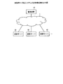
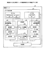
図1は、実施例1に係るシステムの全体構成例を示す図である。図1に示すように、このシステムは、監視装置10、業務サーバ20、業務サーバ30、業務サーバ40を有し、各装置がネットワーク1を介して相互に通信可能に接続される。
[overall structure]
FIG. 1 is a diagram illustrating an example of the overall configuration of a system according to the first embodiment. As shown in FIG. 1, this system includes a
各業務サーバは、アプリケーション(以下、「アプリ」と表記する場合がある)を実行して、クライアント装置等に各種サービスを提供するサーバ装置である。なお、ここでは、3台の業務サーバを例示したが、台数等を限定するものではなく、任意の台数を設置することができる。 Each business server is a server device that executes an application (hereinafter may be referred to as “application”) and provides various services to a client device or the like. Here, three business servers are illustrated, but the number of units is not limited, and an arbitrary number can be installed.
監視装置10は、各業務サーバに監視の設定を要求するサーバ装置である。また、監視装置10は、クライアント装置等からの要求をいずれかの業務サーバに振分けるロードバランサーとしても機能する。例えば、監視装置10は、クライアント装置から要求を受信し、当該要求に対応するサービスを提供する業務サーバの中から、処理負荷等によって振分先の業務サーバを決定して、要求の振分を実行する。
The
このような状態において、各業務サーバは、各業務サーバが監視対象として設定済みか否かを示す各業務サーバの設定情報を含むサーバ情報を受信する。そして、各業務サーバは、受信されたサーバ情報に含まれる設定情報のうち、監視対象として未設定の設定情報に対応する業務サーバを監視対象に設定して監視する。その後、各業務サーバは、監視対象に設定された業務サーバの設定情報を設定済みに更新したサーバ情報を、監視対象に設定された業務サーバに送信する。 In such a state, each business server receives server information including setting information of each business server indicating whether or not each business server has been set as a monitoring target. Then, each business server sets and monitors the business server corresponding to the setting information not set as the monitoring target among the setting information included in the received server information. Thereafter, each business server transmits the server information updated to the setting information of the business server set as the monitoring target to the business server set as the monitoring target.
このように、このシステムでは、サーバ間で各サーバが監視対象に設定済みか否かを示す情報を送受信し、各サーバが監視対象に未設定のサーバを監視対象にするので、各サーバが何れかのサーバを監視することができる。したがって、監視処理の負荷を分散させることができる。 In this way, in this system, information indicating whether or not each server has been set as a monitoring target is transmitted and received between servers, and each server sets a server that has not been set as a monitoring target. That server can be monitored. Therefore, the monitoring processing load can be distributed.
[監視装置の機能構成]
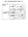
図2は、実施例1に係る監視装置の機能構成を示す機能ブロック図である。図2に示すように、監視装置10は、通信制御部11、記憶部12、制御部13を有する。なお、ここで示した機能部は、例示であり、これに限定されるものではない。例えば、監視装置10は、マウスやキーボードなどの入力部やディスプレイなどの表示部などを有していてもよい。
[Functional configuration of monitoring device]
FIG. 2 is a functional block diagram illustrating the functional configuration of the monitoring apparatus according to the first embodiment. As illustrated in FIG. 2, the
通信制御部11は、各サーバとの間の各種データの送受信を実行する処理部であり、例えばネットワークインタフェースカードなどである。例えば、通信制御部11は、クライアント装置等から受信した要求を各業務サーバに送信し、監視設定に関する各種要求を各業務サーバに送信する。また、通信制御部11は、各業務サーバから、監視設定に関する各種応答を受信する。
The
記憶部12は、制御部13が実行するプログラムや各種データを記憶する記憶装置であり、例えば半導体メモリやハードディスクなどである。この記憶部12は、振分情報DB12aとグループ情報DB12bとを有する。なお、記憶部12は、各業務サーバに設定されるアドレス情報や各業務サーバが実行するサービスに関する情報などを記憶する。
The storage unit 12 is a storage device that stores programs executed by the
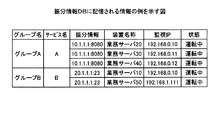
振分情報DB12aは、振分先となる業務サーバに関する振分情報テーブルを記憶する。図3は、振分情報DBに記憶される情報の例を示す図である。図3に示すように、振分情報DB12aは、「グループ名、サービス名、振分情報、装置名称、監視IP、状態」を対応付けて記憶する。ここで記憶される情報は、コマンド受付部14や情報更新部16等によって設定変更される。
The distribution information DB 12a stores a distribution information table related to the business server that is the distribution destination. FIG. 3 is a diagram illustrating an example of information stored in the distribution information DB. As illustrated in FIG. 3, the distribution information DB 12 a stores “group name, service name, distribution information, device name, monitoring IP, and state” in association with each other. The information stored here is set and changed by the
「グループ名」は、グループ化された業務サーバ群を識別する情報である。「サービス名」は、グループ化の対象となるサービス名を示す情報である。「振分情報」は、振分先となる代表IP(Internet Protocol)アドレスとポート番号であり、監視装置10は、この代表IPに対して振分を実行する。「装置名称」は、業務サーバを特定する情報であり、例えばホスト名などが設定される。「監視IP」は、監視に使用するIPアドレスである。「状態」は、業務サーバの状態を示す情報である。
“Group name” is information for identifying a group of business servers. “Service name” is information indicating a service name to be grouped. “Distribution information” is a representative IP (Internet Protocol) address and a port number as a distribution destination, and the
図3の場合、グループAは、サービスAを実行する業務サーバをグループ化したものであり、グループAには、業務サーバ20、業務サーバ30、業務サーバ40が含まれる。また、サービスAの振分情報として、代表IPアドレス「10.1.1.1」とポート番号「8080」が設定されている。また、サービスAの監視用のIPアドレスとして、業務サーバ20には「192.168.0.10」が設定されており、業務サーバ30には「192.168.0.11」が設定されており、業務サーバ40には「192.168.0.12」が設定されており、いずれの業務サーバも正常に動作している。
In the case of FIG. 3, the group A is a group of business servers that execute the service A, and the group A includes the
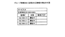
グループ情報DB12bは、振分情報DB12aに記憶される各グループについて、グループに属する業務サーバが監視対象として設定済みか否かを示すグループ情報テーブルを記憶する。図4は、グループ情報DBに記憶される情報の例を示す図である。図4に示すように、グループ情報DB12bは、「サービス、生成時刻、監視IP、状態、監視フラグ」を対応付けて記憶する。ここで記憶される情報は、状態管理部15等によって、グループごとに設定変更される。 The group information DB 12b stores, for each group stored in the distribution information DB 12a, a group information table indicating whether or not a business server belonging to the group has been set as a monitoring target. FIG. 4 is a diagram illustrating an example of information stored in the group information DB. As shown in FIG. 4, the group information DB 12b stores “service, generation time, monitoring IP, status, monitoring flag” in association with each other. The information stored here is set and changed for each group by the state management unit 15 or the like.
「サービス」は、グループ化された業務サーバが共通で実行するサービスを示す。「生成時刻」は、グループ情報テーブルが生成された時刻である。「監視IP」は、監視に使用するIPアドレスである。「状態」は、業務サーバの状態を示す情報である。「監視フラグ」は、監視対象として設定済みか否かを示す。 “Service” indicates a service that is commonly executed by the grouped business servers. “Generation time” is the time when the group information table is generated. “Monitoring IP” is an IP address used for monitoring. “Status” is information indicating the status of the business server. “Monitoring flag” indicates whether or not the monitoring target has been set.
図4は、サービスAのグループAを例にしたグループ情報テーブルである。図4のテーブルは、2013年6月1日9時1分に生成されたテーブルである。また、監視IPとしては、「192.168.0.10」、「192.168.0.11」、「192.168.0.12」が対象となっており、いずれも監視対象として未設定の状態であることを示す。 FIG. 4 is a group information table taking the group A of the service A as an example. The table in FIG. 4 is a table generated at 9:01 on June 1, 2013. The monitoring IPs are “192.168.0.10”, “192.168.0.11”, and “192.168.0.12”, which indicate that they are not set as monitoring targets.
制御部13は、監視装置10全体を司る処理部であり、例えばプロセッサなどである。この制御部13は、クライアント装置から要求を受信し、当該要求に対応するサービスを特定し、特定したサービスの代表IPに対して当該要求を転送する。
The
このような処理以外にも、制御部13は、コマンド受付部14、状態管理部15、情報更新部16を有し、これらによって監視処理を実行する。なお、コマンド受付部14、状態管理部15、情報更新部16は、例えば電子回路やプロセッサが実行するプロセスに該当する。
In addition to such processing, the
コマンド受付部14は、監視情報を定義する処理を実行する。具体的には、コマンド受付部14は、管理者等から、監視対象とするサービスに関するコマンドを受け付けて、当該コマンドを実行して図3に示す情報を更新する。例えば、コマンド受付部14は、当該コマンドによって監視対象のサービスを特定する。また、コマンド受付部14は、受け付けたコマンドを実行して、監視IP、振分情報、装置名称、状態などを更新する。
The
状態管理部15は、監視対象のサービスについて、グループ情報テーブルを生成する処理部である。具体的には、状態管理部15は、コマンド受付部14から指示されたサービスについて、グループ情報テーブルを生成して、グループ情報DB12bに格納する。
The state management unit 15 is a processing unit that generates a group information table for the service to be monitored. Specifically, the state management unit 15 generates a group information table for the service instructed from the
例えば、状態管理部15は、サービスAについての作成指示を受信すると、図3に示す振分情報テーブル12aからサービスAに対応付けられて記憶される「監視IP」、「状態」を抽出して、図4に示すグループ情報テーブルを生成する。このとき、状態管理部15は、生成したグループ情報テーブルに「生成時刻」を付加する。 For example, when receiving the creation instruction for the service A, the state management unit 15 extracts “monitoring IP” and “state” stored in association with the service A from the distribution information table 12a illustrated in FIG. The group information table shown in FIG. 4 is generated. At this time, the state management unit 15 adds “generation time” to the generated group information table.
また、状態管理部15は、生成したグループ情報テーブルの中から監視IPを1つ選択する。そして、状態管理部15は、当該監視IPを宛先にして、生成したグループ情報テーブルを送信し、受信結果応答を受信する。ここで、状態管理部15は、例えば監視装置10とサブネットが近い監視IPを選択して送信することもできる。その後、状態管理部15は、グループ情報テーブルを業務サーバから受信すると、グループ内の各業務サーバに配信されたと確認し、監視が正常に開始されたことを確認する。
Further, the state management unit 15 selects one monitoring IP from the generated group information table. Then, the state management unit 15 transmits the generated group information table with the monitoring IP as a destination, and receives a reception result response. Here, the state management unit 15 can also select and transmit a monitoring IP whose subnet is close to that of the
情報更新部16は、振分情報DB12aを更新して、状態管理部15にグループ情報テーブルの再作成を要求する処理部である。例えば、情報更新部16は、業務サーバ30のサービスAが利用できない故障状態であることを業務サーバ20から受信すると、図3に示した振分情報テーブルにおいて、サービスAの業務サーバ30に対応付けられる「状態」を「故障中」に更新する。そして、情報更新部16は、振分情報テーブルが更新されたので、更新されたグループAに対応するグループ情報テーブルの再作成を状態管理部15に要求する。
The information update unit 16 is a processing unit that updates the distribution information DB 12a and requests the state management unit 15 to recreate the group information table. For example, when the information update unit 16 receives from the
なお、情報更新部16は、故障だけではなく、故障が復旧したことの通知を受信した場合にも、同様に振分情報テーブルを更新して、状態管理部15にグループ情報テーブルの再作成を要求することもできる。 Note that the information update unit 16 updates the distribution information table in the same manner when notifying not only the failure but also that the failure has been recovered, and re-creates the group information table in the state management unit 15. It can also be requested.
[業務サーバの機能構成]
次に、業務サーバの機能構成について説明するが、ここでは、一例として業務サーバ20を例にして説明する。
[Functional configuration of business server]
Next, the functional configuration of the business server will be described. Here, the
図5は、実施例1に係る業務サーバの機能構成を示す機能ブロック図である。図5に示すように、業務サーバ20は、受信部21、記憶部22、アプリ実行部23、サービスA監視機能部24、サービスB監視機能部25を有する。ここで、サービス監視機能部は、業務サーバで実行されているサービスごとに設けられる。
FIG. 5 is a functional block diagram illustrating the functional configuration of the business server according to the first embodiment. As illustrated in FIG. 5, the
なお、ここで示した機能部は、例示であり、これに限定されるものではない。また、受信部21、アプリ実行部23、サービスA監視機能部24、サービスB監視機能部25は、例えば電子回路やプロセッサが実行するプロセスなどである。
In addition, the function part shown here is an illustration and is not limited to this. The receiving unit 21, the
受信部21は、各サーバとの間の各種データの送受信を実行する処理部であり、例えばネットワークインタフェースカードなどを有する。例えば、受信部21は、監視装置10や他の業務サーバから、グループ情報テーブルを受信する。そして、受信部21は、受信したグループ情報テーブルから該当するサービスを特定する。その後、受信部21は、特定したサービスに対応するサービス監視機能部に、受信したグループ情報テーブルを出力する。
The receiving unit 21 is a processing unit that executes transmission and reception of various data with each server, and includes, for example, a network interface card. For example, the receiving unit 21 receives a group information table from the
また、受信部21は、監視装置10から振分けられた、クライアント装置等から要求を受信する。そして、受信部21は、受信した要求から該当するサービスを特定し、特定したサービスを提供するアプリケーションに、当該要求を出力する。
The receiving unit 21 receives a request from a client device or the like distributed from the
記憶部22は、アプリ実行部23や各監視機能部が実行するプログラムや各種データを記憶する記憶装置であり、例えば半導体メモリやハードディスクなどである。記憶部22は、グループA情報テーブル22aとグループB情報テーブル22bとを記憶する。
The storage unit 22 is a storage device that stores programs executed by the
各グループ情報テーブルは、監視装置10から受信されるテーブルであり、各監視機能部によって記憶部22に格納される。例えば、グループA情報テーブル22aは、サービスAについてグループ化されたグループAに対するテーブルであり、グループB情報テーブル22bサービスBについてグループ化されたグループBに対するテーブルである。
Each group information table is a table received from the
アプリ実行部23は、アプリケーションを実行してサービスを提供する処理部である。具体的には、アプリ実行部23は、記憶部22からアプリケーションのプログラムを読み出して実行して、各種サービスを起動させる。
The
図5の例では、アプリ実行部23は、アプリAを実行して、サービスA1とサービスA2とを起動させている。また、アプリ実行部23は、アプリBを実行して、サービスB1を起動させている。
In the example of FIG. 5, the
サービスA監視機能部24とサービスB監視機能部25は、サービスによって監視手法が異なるが、同様の処理を実行するので、サービスA監視機能部24について説明する。サービス監視機能部24は、設定部24a、通知部24b、監視部24cを有する。
The service A
設定部24aは、同一グループに属する各業務サーバが監視対象として設定済みか否かを示す監視フラグを含むグループA情報テーブル内の各サーバ装置のうち、監視対象として未設定の業務サーバを監視対象に設定する処理部である。
The
例えば、設定部24aは、受信されたグループA情報テーブル内のいずれの監視フラグも未設定であり、監視フラグに「配備起点」が設定されていない場合、自サーバの監視IPに対応する監視フラグに「配備起点」を設定する。その後、設定部24aは、監視フラグが未設定の監視IPの中から1つの監視IPを選択して、選択した監視IPに対応する監視フラグに「監視選択済」を設定する。ここで、設定部24aは、例えば自サーバとサブネットが近い監視IPを選択することもできる。
For example, if any monitoring flag in the received group A information table is not set and “deployment start point” is not set in the monitoring flag, the
このようにして、設定部24aは、いずれかの監視フラグに「監視選択済」を設定したグループA情報テーブルを通知部24bに出力する。また、設定部24aは、設定された「監視選択済」を「監視中」に設定し直したグループA情報テーブルを、記憶部22に格納する。
In this way, the
通知部24bは、設定部24aから入力されたグループA情報テーブルを、監視対象に設定された業務サーバに送信する処理部である。例えば、通知部24bは、業務サーバ30のサービスAが監視対象に設定された場合、業務サーバ30の監視IPに対応する監視フラグが「監視選択済」に設定されたグループA情報テーブルを、業務サーバ30の監視IPに送信する。
The
監視部24cは、対象サービスを監視する処理部である。例えば、監視部24cは、グループA情報テーブル22aを参照し、監視対象に設定されている業務サーバ30のサービスAを監視する。監視部24cが監視する手法は、サービスに特化した監視手法を用いる。
The
一例を挙げると、監視部24cは、SIP(Session Initiation Protocol)サービスが監視対象の場合、試験呼を送信して応答があるか否かによってサービスを監視する。また、監視部24cは、Webサービスが監視対象の場合、HTTP(Hypertext Transfer Protocol)リクエストを送信してHTTP応答を受信するか否かによってサービスを監視する。なお、監視部24cは、サービスによっては、SNMP(Simple Network Management Protocol)やICMP(Internet Control Message Protocol)なども利用できる。
For example, when a SIP (Session Initiation Protocol) service is a monitoring target, the
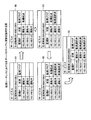
[テーブル更新例]
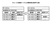
次に、業務サーバ20を例にして、グループA情報テーブルの更新例を説明する。図6と図7は、グループA情報テーブルの更新例を説明する図である。業務サーバ20の設定部24aは、図4に示したグループA情報テーブルを監視装置10から受信する。そして、設定部24aは、テーブル内のいずれの監視フラグにも「配備起点」が設定されていないので、図6の左図に示すように、自サーバの監視IP「192.168.0.10」に対応する監視フラグに「配備起点」を設定する。
[Table update example]
Next, an example of updating the group A information table will be described using the
その後、設定部24aは、グループA情報テーブルにおいて監視フラグが設定されていない業務サーバの中から、監視IP「192.168.0.11」を監視対象に決定すると、当該監視IPに対応する監視フラグに「監視選択済」を設定する。この状態のグループA情報テーブルが、「192.168.0.11」に対応する業務サーバに送信される。
After that, when setting the monitoring IP “192.168.0.11” as the monitoring target from among the business servers for which the monitoring flag is not set in the group A information table, the
一方、設定部24aは、図6の右図に示すように、監視IP「192.168.0.11」に対応する監視フラグを「監視選択済」から「監視中」に設定し直したグループA情報テーブルを記憶部22に格納する。このようにすることで、どのサーバのどのサービスが監視対象として設定されているかを認識することができる。
On the other hand, as shown in the right diagram of FIG. 6, the setting
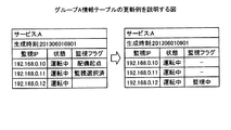
また、図7の左図に示すように、グループA情報テーブルにおいて、すでに「配備起点」と「監視選択済」が設定されている場合もある。この場合、設定部24aは、図7の右図に示すように、監視フラグに何も設定されていない監視IP「192.168.0.12」を監視対象に設定する。
Further, as shown in the left diagram of FIG. 7, “deployment start point” and “monitoring selected” may already be set in the group A information table. In this case, as illustrated in the right diagram of FIG. 7, the setting
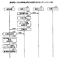
[処理の流れ]
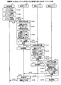
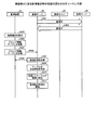
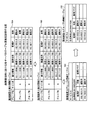
次に、図8と図9を用いて、監視対象に設定する処理の流れを説明する。図8は、実施例1に係るシステムが実行する処理の流れを示すシーケンス図である。図9は、処理シーケンスにおける各サーバのテーブル更新を説明する図である。
[Process flow]
Next, the flow of processing for setting a monitoring target will be described with reference to FIGS. FIG. 8 is a sequence diagram illustrating the flow of processing executed by the system according to the first embodiment. FIG. 9 is a diagram for explaining the table update of each server in the processing sequence.
図8に示すように、監視装置10のコマンド受付部14は、コマンドを受け付けて実行し、監視対象のサービスAを特定する(S101)。続いて、状態管理部15は、図9の9Aに示すように、サービスAを実行する業務サーバをグループ化したグループAについて、グループA情報テーブルを生成する(S102)。その後、状態管理部15は、図9の9Aに示すグループA情報テーブルを、当該テーブル内の監視IP「192.168.0.10」に送信する(S103とS104)。
As shown in FIG. 8, the
そして、監視IP「192.168.0.10」に対応する業務サーバ20は、監視装置10からグループA情報テーブルを受信すると、受信応答を監視装置10に送信する(S105とS106)。このとき、業務サーバ20は、当該テーブルの送信元である監視装置10のIPアドレスとを保持する。
When the
その後、業務サーバ20は、受信したグループA情報テーブル内の監視フラグが全部未設定なので、図9の9Bに示すように、自サーバの監視IP「192.168.0.10」に対応する監視フラグに「配備起点」を設定する(S107)。
After that, since all the monitoring flags in the received group A information table are not set, the
続いて、業務サーバ20は、監視フラグの未設定のサーバがあるので、任意の未設定のサーバを監視対象に設定する(S108)。具体的には、図9の9Cに示すように、業務サーバ20は、監視フラグが未設定の監視IP「192.168.0.11」を監視対象に設定して、当該監視IPに対応する監視フラグを「監視選択済」を設定する。
Subsequently, since the
その後、業務サーバ20は、監視フラグを設定した監視IP「192.168.0.11」に対して、図9の9Cに示すグループA情報テーブルを送信する(S109とS110)。
Thereafter, the
そして、業務サーバ20は、監視IP「192.168.0.11」の監視を開始する(S111)。例えば、業務サーバ20は、監視IP「192.168.0.11」のサービスAについて、自サーバ内でサービスAを実行する処理部等を用いて、サービスAに特化した監視手法で監視する。
Then, the
一方で、監視IP「192.168.0.11」に対応する業務サーバ30は、図9の9Cに示すグループA情報テーブルを受信すると、送信元の業務サーバ20に対して、受信応答を送信する(S112とS113)。
On the other hand, when the
続いて、業務サーバ30は、監視フラグの未設定のサーバがあるので、任意の未設定のサーバを監視対象に設定する(S114)。具体的には、図9の9Dに示すように、業務サーバ30は、監視フラグが未設定の監視IP「192.168.0.12」を監視対象に設定して、当該監視IPに対応する監視フラグを「監視選択済」を設定する。
Subsequently, since there is a server for which the monitoring flag is not set, the
その後、業務サーバ30は、監視フラグを設定した監視IP「192.168.0.12」に対して、図9の9Dに示すグループA情報テーブルを送信する(S115とS116)。
Thereafter, the
そして、業務サーバ30は、監視IP「192.168.0.12」の監視を開始する(S117)。業務サーバ20と同様、業務サーバ30は、監視IP「192.168.0.12」のサービスAについて、自サーバ内でサービスAを実行する処理部等を用いて、サービスAに特化した監視手法で監視する。
Then, the
一方で、監視IP「192.168.0.12」に対応する業務サーバ40は、図9の9Dに示すグループA情報テーブルを受信すると、送信元の業務サーバ30に対して、受信応答を送信する(S118とS119)。
On the other hand, when receiving the group A information table shown in 9D of FIG. 9, the
続いて、業務サーバ40は、テーブル内の監視フラグが全て設定済みなので、配備起点が設定されている業務サーバを監視対象に設定する(S120)。具体的には、図9の9Eに示すように、業務サーバ40は、監視フラグに「配備起点」が設定されている監視IP「192.168.0.10」を監視対象に設定して、当該監視IPに対応する監視フラグに「監視選択済」を設定する。
Subsequently, since all the monitoring flags in the table have been set, the
その後、業務サーバ40は、監視フラグを設定した監視IP「192.168.0.10」に対して、図9の9Eに示すグループA情報テーブルを送信する(S121とS122)。また、そして、業務サーバ40は、他の業務サーバと同様、監視IP「192.168.0.10」の監視を開始する(S123)。
Thereafter, the
一方で、監視IP「192.168.0.10」に対応する業務サーバ10は、図9の9Eに示すグループA情報テーブルを受信すると、送信元の業務サーバ40に対して、受信応答を送信する(S124とS125)。そして、業務サーバ10は、受信したグループA情報テーブルの監視フラグが全て監視対象済に設定されているので、テーブルの配備を完了し、配備完了通知を監視装置10に送信する(S126とS127)。このようにして、監視装置10は、サービスAを実行する各業務サーバ間で、監視が開始されたことを認識する。
On the other hand, when receiving the group A information table indicated by 9E in FIG. 9, the
[効果]
このように、複数台の業務サーバと監視装置で構成されるシステムにおいて、監視装置が監視するべき監視対象数や監視方式に影響されることなく、監視を行うための監視処理負荷を軽減させることができる。また、業務サーバの台数が増えても、監視負荷はそれに比例しない監視ができる。
[effect]
In this way, in a system consisting of multiple business servers and monitoring devices, the monitoring processing load for monitoring can be reduced without being affected by the number of monitoring targets and the monitoring method to be monitored by the monitoring device Can do. Even if the number of business servers increases, the monitoring load can be monitored in proportion to it.
また、監視装置10内に監視を行うための個別機能の実装を行わずに、各業務サーバの監視を実行できる。また、サービスごとに、当該サービスを実行する業務サーバ間で監視することができ、当該サービスに特化した最適な監視ができる。
Further, it is possible to monitor each business server without implementing an individual function for monitoring in the
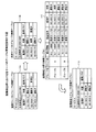
ところで、監視装置10は、故障が検出された場合には、新たなグループテーブルを生成して、監視の再設定を実行することができる。そこで、実施例2では、図10と図11とを用いて、故障の検出から監視の再設定までの処理について説明する。ここでは、一例として、上述したサービスAの監視を対象とする。
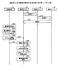
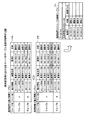
By the way, when a failure is detected, the
図10は、実施例2に係る故障検出時の処理の流れを示すシーケンス図である。図11は、故障検出時における各サーバのテーブル更新を説明する図である。 FIG. 10 is a sequence diagram illustrating a process flow when a failure is detected according to the second embodiment. FIG. 11 is a diagram for explaining the table update of each server when a failure is detected.
図10に示すように、業務サーバ20は、業務サーバ30に監視信号を送信する(S201とS202)。その後、業務サーバ20は、一定時間経過後も応答を受信しないので、応答未検出と判定する(S203)。
As shown in FIG. 10, the
すると、業務サーバ20は、業務サーバ30を故障と判定し、グループA情報テーブルを更新する(S204)。そして、業務サーバ20は、更新した故障通知を監視装置10に送信する(S205とS206)。
Then, the
具体的には、業務サーバ20は、図11の11Aに示すように、業務サーバ30の監視IP「192.168.0.11」を監視している状態で、業務サーバ30の故障を検出する。この場合、業務サーバ20は、図11の11Bに示すように、業務サーバ30の監視IP「192.168.0.11」に対応する「状態」を「運転中」から「故障」に更新する。そして、業務サーバ20は、図11の11Bに示すグループA情報テーブルを、監視装置10に送信する。
Specifically, the
そして、監視装置10は、業務サーバ20から受信した故障通知に対して、故障通知応答を業務サーバ20に送信する(S207とS208)。なお、ここでは、監視装置10は、故障通知として、図11の11Bに示したグループA情報テーブルを受信する。
In response to the failure notification received from the
続いて、監視装置10は、受信した故障通知に基づいて振分情報テーブルを更新する(S209)。具体的には、監視装置10は、受信したグループA情報テーブルから、監視IP「192.168.0.11」の状態が「故障」であることを検出する。そして、監視装置10は、図11の11Cに示すように、振分情報テーブルにおいて監視IP「192.168.0.11」に対応付けられる「状態」を、「運転中」から「故障」に更新する。
Subsequently, the
その後、監視装置10は、更新後の振分情報テーブルにおいて、更新されたグループAについてのグループA情報テーブルを再作成し(S210)、監視設定処理を実行する(S211)。
Thereafter, the
具体的には、監視装置10は、図11の11Cに示す監視IP「192.168.0.11」が「故障」に設定される振分情報テーブルから、グループAに属する業務サーバの情報を抽出して、新たなグループA情報テーブルを生成する。このとき、監視装置10は、図11の11Dに示すように、故障中の業務サーバ30に関する情報を除き、業務サーバ20の監視IP「192.168.0.10」と業務サーバ40の監視IP「192.168.0.12」とに関する情報を抽出する。なお、監視装置10が新たに生成したグループA情報テーブルについて実行する監視設定処理は、図8と同様なので、詳細な説明は省略する。
Specifically, the
このように、監視装置10は、業務サーバの故障を他の業務サーバから受信して、再度監視設定をし直すことができる。したがって、業務サーバが故障した場合でも、故障した業務サーバを除いた監視が設定でき、故障後であっても、監視対象が監視されない事象の発生を抑制でき、漏れのない監視を実現することができる。
As described above, the
ところで、他の業務サーバの故障を検出した業務サーバと、監視装置10との間のサービス間通信が確立できない場合、監視装置10への故障通知が実行されず、監視されない業務サーバが発生する。このような場合でも、正常な業務サーバが故障通知を代行することで、漏れのない監視を実現することができる。
By the way, when the inter-service communication between the business server that has detected a failure of another business server and the
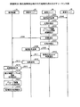
そこで、実施例3では、図12と図13とを用いて、故障の検出、代行通知、監視の再設定の一連の流れについて説明する。ここでは、一例として、上述したサービスAの監視を対象とする。また、代行通知に関する処理は、一例として、各業務サーバの監視部が実行する。 Therefore, in the third embodiment, a series of flows of failure detection, proxy notification, and monitoring resetting will be described with reference to FIGS. 12 and 13. Here, as an example, the above-described monitoring of the service A is targeted. Further, as an example, the processing related to proxy notification is executed by the monitoring unit of each business server.
図12は、実施例3に係る故障検出時の代行処理の処理の流れを示すシーケンス図である。図13は、故障検出の代行処理時における各サーバのテーブル更新を説明する図である。 FIG. 12 is a sequence diagram illustrating a flow of a proxy process when a failure is detected according to the third embodiment. FIG. 13 is a diagram for explaining the table update of each server during the failure detection proxy process.
図12に示すように、業務サーバ30は、業務サーバ40に監視信号を送信する(S301とS302)。その後、業務サーバ30は、一定時間経過後も応答を受信しないので、応答未検出と判定する(S303)。すると、業務サーバ30は、業務サーバ40を故障と判定し、グループA情報テーブルを更新する(S304)。
As illustrated in FIG. 12, the
具体的には、業務サーバ30は、業務サーバ40の監視IP「192.168.0.12」を監視している状態で、業務サーバ40の故障を検出する。この場合、業務サーバ30は、図13の13Aに示すように、業務サーバ40の監視IP「192.168.0.12」に対応する「状態」を「運転中」から「故障」に更新する。
Specifically, the
そして、業務サーバ30は、更新した故障通知を監視装置10に送信する(S305とS306)。具体的には、業務サーバ30は、図13の13Aに示すグループA情報テーブルを、監視装置10に送信する。
Then, the
その後、業務サーバ30は、一定時間経過後も監視装置10から応答を受信しないので、応答未検出と判定する(S307)。このとき、業務サーバ30は、自サーバと監視装置10間の通信断を検出する。
Thereafter, the
このような状態において、業務サーバ20は、業務サーバ30に監視信号を送信する(S308とS309)。この監視信号を受信した業務サーバ30は、監視応答および故障通知を業務サーバ20に応答する(S310とS311)。具体的には、業務サーバ30は、業務サーバ40の故障通知と、自サーバと監視装置10間のネット障害の通知とを含めた応答を、業務サーバ20に送信する。
In such a state, the
その後、業務サーバ20は、業務サーバ30から監視応答とともに受信した故障通知にしたがって、監視装置10に故障を通知する(S312とS313)。具体的には、業務サーバ20は、業務サーバ40の故障通知と、業務サーバ30のネット障害とを受信する。そして、業務サーバ20は、図13の13Bに示すように、自サーバが保持するグループA情報テーブルにおいて、業務サーバ40の監視IP「192.168.0.12」に対応する状態に「故障」を設定する。同様に、業務サーバ20は、図13の13Bに示すように、自サーバが保持するグループA情報テーブルにおいて、業務サーバ30の監視IP「192.168.0.11」に対応する状態に「ネット異常」を設定する。そして、業務サーバ20は、更新した図13の13Bに示すグループA情報テーブルを、監視装置10に送信する。
Thereafter, the
そして、監視装置10は、業務サーバ20から受信した故障通知に対して、故障通知応答を業務サーバ20に送信する(S314とS315)。続いて、監視装置10は、受信した故障通知に基づいて振分情報テーブルを更新する(S316)。
Then, the
具体的には、監視装置10は、受信したグループA情報テーブルから、監視IP「192.168.0.11」の状態が「ネット異常」であること、監視IP「192.168.0.12」の状態が「故障」であることを検出する。そして、監視装置10は、図13の13Cに示すように、振分情報テーブルにおいて監視IP「192.168.0.12」に対応付けられる「状態」を、「運転中」から「故障」に更新する。同様に、監視装置10は、振分情報テーブルにおいて監視IP「192.168.0.11」に対応付けられる「状態」を、「運転中」から「ネット異常」に更新する。
Specifically, the
その後、監視装置10は、更新後の振分情報テーブルにおいて、更新されたグループAについてのグループA情報テーブルを再作成し(S317)、監視設定処理を実行する(S318)。
Thereafter, the
具体的には、監視装置10は、図13の13Cに示す振分情報テーブルから、グループAに属する業務サーバの情報を抽出して、新たなグループA情報テーブルを生成する。このとき、監視装置10は、図13の13Dに示すように、故障中の業務サーバ30および業務サーバ40に関する情報を除き、業務サーバ20の監視IP「192.168.0.10」に関する情報を抽出する。なお、監視装置10が新たに生成したグループA情報テーブルについて実行する監視設定処理は、図8と同様なので、詳細な説明は省略する。
Specifically, the
このように、他の業務サーバの故障を検出した業務サーバが、監視装置10に故障を通知できない状態であっても、他の正常な業務サーバが故障通知を代行して、監視装置10に通知することができる。したがって、ネット故障やサービス異常が併発した場合でも、漏れのない監視を実現することができる。
In this way, even if the business server that has detected a failure of another business server is in a state where it cannot notify the
ところで、本システムは、業務サーバの故障が復旧した場合には、監視の再設定を自動で再開することができる。そこで、実施例4では、故障復旧時の処理について説明する。ここでは、一例として、業務サーバ30のサービスAの故障が復旧した例で説明する。また、監視の再設定に関する処理は、一例として、各業務サーバの監視部が実行する。
By the way, this system can automatically resume the monitoring resetting when the failure of the business server is recovered. Thus, in the fourth embodiment, processing at the time of failure recovery will be described. Here, as an example, an example in which the failure of the service A of the
図14は、実施例4に係る故障復旧時の処理の流れを示すシーケンス図である。図15は、故障復旧時における各サーバのテーブル更新を説明する図である。 FIG. 14 is a sequence diagram illustrating the flow of processing at the time of failure recovery according to the fourth embodiment. FIG. 15 is a diagram illustrating table update of each server at the time of failure recovery.
図14に示すように、業務サーバ20が業務サーバ40を監視しており(S401)、業務サーバ40が業務サーバ20を監視しており(S402)、業務サーバ30のサービスAが故障している状態を想定する。なお、各業務サーバは、監視対象の業務サーバ全体等ではなく、監視対象の業務サーバのサービスAを監視しているものとする。
As shown in FIG. 14, the
この状態では、監視装置10は、図15の15Aに示す振分情報テーブルを保持している。具体的には、振分情報テーブルでは、サービスAにおける業務サーバ30と対応付けられる状態が「故障」となっている。
In this state, the
このような状態で、監視装置10は、管理者等から業務サーバ30のサービスAの復旧通知を受け付けると(S403)、グループA情報テーブルを更新する(S404)。その後、監視装置10は、更新したグループA情報テーブルを業務サーバ20に送信する(S405とS406)。
In this state, when the
具体的には、監視装置10は、図15の15Bに示すように、振分情報テーブル上で、サービスAにおける業務サーバ30と対応付けられる状態を「故障」から「運転中」に更新する。その後、監視装置10は、振分情報テーブルにおいてグループAに対する情報を抽出してグループA情報テーブルを生成する。具体的には、監視装置10は、図15の15Cに示すように、業務サーバ30が含まれてないグループA情報テーブルから、図15の15Dに示すように、業務サーバ30が含まれるグループA情報テーブルを再作成する。
Specifically, as illustrated in 15B of FIG. 15, the
そして、業務サーバ20は、監視装置10からグループA情報テーブルを受信すると、受信応答を監視装置10に送信する(S407とS408)。その後、受信したグループA情報テーブルと、記憶部22に既に記憶されるグループA情報テーブルとについて、生成時刻を比較して、最新のグループA情報テーブルを特定する(S409)。
When the
ここでは、業務サーバ20は、S406で受信した図15の15Dに示すグループA情報テーブルが最新と判定する(S410)。すると、業務サーバ20は、図15の15Dに示すグループA情報テーブルに基づいて、監視設定処理を開始する(S411)。
Here, the
このように、各業務サーバは、故障中の業務サーバが復旧した場合、監視の再設定を自動で再開することができる。したがって、管理者が監視の再設定等を行う作業負担を軽減することができる。さらに、実施例1と同様の手法で、各業務サーバは、監視設定を順に実行することができるので、漏れのない監視設定を行うことができる。 In this way, each business server can automatically restart the monitoring resetting when the business server in failure is restored. Therefore, it is possible to reduce the work load for the administrator to reset the monitoring. Furthermore, since each business server can execute monitoring settings in order by the same method as in the first embodiment, it is possible to perform monitoring settings without omission.
ところで、本システムは、業務サーバが新たに追加された場合でも、監視の再設定を自動で実行することができる。そこで、実施例5では、構成変更時の処理について説明する。ここでは、一例として、サービスAのグループAを例にして、業務サーバ50上で新たにサービスAが実行されたことで、グループAに業務サーバ50が追加される例で説明する。 By the way, this system can automatically execute monitoring resetting even when a business server is newly added. Therefore, in the fifth embodiment, processing at the time of configuration change will be described. Here, as an example, the group A of the service A is taken as an example, and an example in which the business server 50 is added to the group A when the service A is newly executed on the business server 50 will be described.
図16は、実施例5に係る構成変更時の処理の流れを示すシーケンス図である。図17は、構成変更時における各サーバのテーブル更新を説明する図である。ここでは、一例として、上述したサービスAの監視を対象とする。また、構成変更に関する処理は、一例として、各業務サーバの監視部が実行する。 FIG. 16 is a sequence diagram illustrating the flow of processing when changing the configuration according to the fifth embodiment. FIG. 17 is a diagram for explaining the table update of each server when the configuration is changed. Here, as an example, the above-described monitoring of the service A is targeted. Further, as an example, the processing related to the configuration change is executed by the monitoring unit of each business server.
図16に示すように、業務サーバ20が業務サーバ30を監視しており(S501)、業務サーバ30が業務サーバ40を監視しており(S502)、業務サーバ40が業務サーバ20を監視している(S503)。なお、各業務サーバは、監視対象の業務サーバ全体等ではなく、監視対象の業務サーバのサービスAを監視しているものとする。
As shown in FIG. 16, the
この状態では、監視装置10は、図17の17Aに示すように、図3と同様の振分情報テーブルを保持している。具体的には、図17の17Aに示す振分情報テーブルは、サービスAにおける業務サーバとして、業務サーバ20、業務サーバ30、業務サーバ40とが設定されており、各業務サーバが正常に動作している情報を保持する。
In this state, the
このような状態において、監視装置10は、構成変更を受け付けると(S504)、振分情報テーブルおよびグループA情報テーブルを更新する(S505)。
In such a state, when receiving a configuration change (S504), the
具体的には、監視装置10は、グループAに「業務サーバ50、監視IP(192.168.0.14)、運転中」を追加する指示を受け付ける。すると、監視装置10は、図17の17Bに示すように、振分情報テーブルにおけるグループAに対して、「振分情報(10.1.1.1:8080)、業務サーバ50、監視IP(190.168.0.14)、運転中」の新たなレコードを追加する。
Specifically, the
続いて、監視装置10は、更新した図17の17Bに示す振分情報テーブルから、グループAに該当する情報を抽出して、図17の17Cに示すグループA情報テーブルを生成する。具体的には、監視装置10は、サービスAを実行する業務サーバ20、30、40、50の各サーバの監視IPと状態とを抽出したグループA情報テーブルを生成する。
Subsequently, the
そして、監視装置10は、更新したグループA情報テーブルを業務サーバ20に送信する(S506とS507)。なお、その後の処理であるS508からS512は、図14で説明したS407からS411まで同様の処理なので、詳細な説明は省略する。
Then, the
このように、業務サーバが新たに追加された場合でも、現在の監視設定を中止することなく、監視を続けたまま、監視の再設定を自動で実行することができる。 As described above, even when a business server is newly added, it is possible to automatically execute the monitoring resetting while continuing the monitoring without stopping the current monitoring setting.
さて、これまで本発明の実施例について説明したが、本発明は上述した実施例以外にも、種々の異なる形態にて実施されてよいものである。そこで、以下に異なる実施例を説明する。 Although the embodiments of the present invention have been described so far, the present invention may be implemented in various different forms other than the embodiments described above. Therefore, different embodiments will be described below.
(グループ)
上記実施例では、同一サービスを実行する業務サーバでグループ化する例を説明したが、これに限定されるものではない。例えば、同一地域、同一ネットワーク、同一企業など任意にグループ化することができる。
(group)
In the above-described embodiment, an example in which business servers that perform the same service are grouped has been described. However, the present invention is not limited to this. For example, the same region, the same network, the same company, etc. can be arbitrarily grouped.
(サービス)
上記実施例では、サービスAについて説明したが、1つの業務サーバがサービスAとサービスBとを実行する場合、両方のサービスについて上記処理が実行される。例えば、業務サーバ20でサービスAとサービスBが実行され、業務サーバ30でサービスAとサービスCが実行されるとする。
(service)
In the above embodiment, the service A has been described. However, when one business server executes the service A and the service B, the above processing is executed for both services. For example, it is assumed that service A and service B are executed by the
この場合、業務サーバ20は、サービスAのグループAとサービスBのグループBの属し、グループAに属する他の業務サーバのサービスAの監視と、グループBに属する他の業務サーバのサービスBを監視する。同様に、業務サーバ30は、サービスAのグループAとサービスCのグループCの属し、グループAに属する他の業務サーバのサービスAの監視と、グループCに属する他の業務サーバのサービスCを監視する。
In this case, the
つまり、同一システムに属する業務サーバであっても、実行しているサービスによって監視処理の数が異なる。このように、業務サーバ自体ではなく、サービスごとに当該サービスを実行する業務サーバ間で監視設定を実行するので、実行していないサービスを監視することなく、監視処理の負荷軽減が実現できる。 That is, even for business servers belonging to the same system, the number of monitoring processes differs depending on the service being executed. As described above, since the monitoring setting is performed between the business servers that execute the service for each service, not the business server itself, the monitoring processing load can be reduced without monitoring the service that is not being executed.
(システム)
また、本実施例において説明した各処理のうち、自動的におこなわれるものとして説明した処理の全部または一部を手動的におこなうこともできる。あるいは、手動的におこなわれるものとして説明した処理の全部または一部を公知の方法で自動的におこなうこともできる。この他、上記文書中や図面中で示した処理手順、制御手順、具体的名称、各種のデータやパラメータを含む情報については、特記する場合を除いて任意に変更することができる。
(system)
In addition, among the processes described in the present embodiment, all or a part of the processes described as being automatically performed can be manually performed. Alternatively, all or part of the processing described as being performed manually can be automatically performed by a known method. In addition, the processing procedure, control procedure, specific name, and information including various data and parameters shown in the above-described document and drawings can be arbitrarily changed unless otherwise specified.
また、図示した各装置の各構成要素は機能概念的なものであり、必ずしも物理的に図示の如く構成されていることを要しない。すなわち、各装置の分散や統合の具体的形態は図示のものに限られない。つまり、その全部または一部を、各種の負荷や使用状況などに応じて、任意の単位で機能的または物理的に分散・統合して構成することができる。さらに、各装置にて行なわれる各処理機能は、その全部または任意の一部が、CPUおよび当該CPUにて解析実行されるプログラムにて実現され、あるいは、ワイヤードロジックによるハードウェアとして実現され得る。 Further, each component of each illustrated apparatus is functionally conceptual, and does not necessarily need to be physically configured as illustrated. That is, the specific form of distribution and integration of each device is not limited to the illustrated one. That is, all or a part of them can be configured to be functionally or physically distributed / integrated in arbitrary units according to various loads or usage conditions. Further, all or any part of each processing function performed in each device may be realized by a CPU and a program analyzed and executed by the CPU, or may be realized as hardware by wired logic.
(ハードウェア)
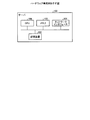
図18は、ハードウェア構成例を示す図である。図18に示すハードウェア構成は、図1等に示した各サーバや装置のハードウェア構成である。図18に示すように、サーバ100は、ネットワークインタフェース101、記憶装置102、メモリ103、CPU(Central Processing Unit)104を有する。また、図18に示した各部は、バス等で相互に接続される。
(hardware)
FIG. 18 is a diagram illustrating a hardware configuration example. The hardware configuration shown in FIG. 18 is the hardware configuration of each server or apparatus shown in FIG. As illustrated in FIG. 18, the
ネットワークインタフェース101は、ネットワークインタフェースカードなどである。記憶装置102は、ハードディスクなどの記憶装置であり、図2や図5に示した機能を動作させるプログラム、図2や図5に示した各DBやテーブルを記憶する。記録装置の例としては、ROM(Read Only Memory)、RAM、CD−ROM等の他のコンピュータが読み取り可能な記録媒体に各種プログラムを格納しておき、コンピュータに読み取らせることとしてもよい。なお、記録媒体を遠隔地に配置し、コンピュータが、その記憶媒体にアクセスすることでプログラムを取得して利用してもよい。また、その際、取得したプログラムをそのサーバ100自身の記録媒体に格納して用いてもよい。
The
CPU104は、図2または図5に示した各処理部と同様の処理を実行するプログラムを記憶装置102等から読み出してメモリ103に展開することで、図2または図5等で説明した各機能を実行するプロセスを動作させる。すなわち、サーバ100が監視装置の場合、このプロセスは、監視装置10が有する各処理と同様の機能を実行する。具体的には、CPU104は、コマンド受付部14、状態管理部15、情報更新部16と同様の機能を有するプログラムを記憶装置102等から読み出す。そして、CPU104は、各処理部と同様の処理を実行するプロセスを実行する。
The
また、サーバ100が業務サーバの場合、このプロセスは、業務サーバが有する各処理と同様の機能を実行する。具体的には、CPU104は、設定部24a、通知部24b、監視部24cと同様の機能を有するプログラムを記憶装置102等から読み出す。そして、CPU104は、各処理部と同様の処理を実行するプロセスを実行する。
When the
このようにサーバ100は、プログラムを読み出して実行することで監視方法を実行する情報処理装置として動作する。また、サーバ100は、媒体読取装置によって記録媒体から上記プログラムを読み出し、読み出された上記プログラムを実行することで上記した実施例と同様の機能を実現することもできる。なお、この他の実施例でいうプログラムは、サーバ100によって実行されることに限定されるものではない。例えば、他のコンピュータまたはサーバがプログラムを実行する場合や、これらが協働してプログラムを実行するような場合にも、本発明を同様に適用することができる。
As described above, the
10 監視装置
11 通信制御部
12 記憶部
12a 振分情報DB
12b グループ情報DB
13 制御部
14 コマンド受付部
15 状態管理部
16 情報更新部
20、30、40 業務サーバ
21 受信部
22 記憶部
22a グループA情報テーブル
22b グループB情報テーブル
23 アプリ実行部
24 サービスA監視機能部
24a 設定部
24b 通知部
24c 監視部
25 サービスB監視機能部
DESCRIPTION OF
12b Group information DB
DESCRIPTION OF
Claims (7)
前記受信部によって受信された前記サーバ情報に含まれる設定情報のうち、監視対象として未設定の設定情報に対応するデータ処理装置を監視対象に設定して監視する監視部と、
前記監視部によって前記監視対象に設定されたデータ処理装置の設定情報を設定済みに更新した前記サーバ情報を、前記監視対象に設定されたデータ処理装置に送信する送信部と、
を有することを特徴とするデータ処理装置。 A receiving unit that receives server information including setting information of each data processing device indicating whether or not each data processing device has been set as a monitoring target;
Among the setting information included in the server information received by the receiving unit, a monitoring unit that sets and monitors a data processing device corresponding to setting information that is not set as a monitoring target, and
A transmission unit configured to transmit the server information, which has been updated to the setting information of the data processing device set as the monitoring target by the monitoring unit, to the data processing device set as the monitoring target;
A data processing apparatus comprising:
前記監視部は、前記受信部によって受信された前記サーバ情報に含まれる設定情報のうち、監視対象として未設定である1台のデータ処理装置を監視対象に設定し、前記監視対象に設定されたデータ処理装置の前記サービスを監視することを特徴とする請求項1に記載のデータ処理装置。 The receiving unit receives the server information including the setting information of each data processing device grouped by a data processing device that provides the same service,
The monitoring unit sets one data processing device that is not set as a monitoring target among the setting information included in the server information received by the receiving unit, and is set as the monitoring target The data processing apparatus according to claim 1, wherein the service of the data processing apparatus is monitored.
各データ処理装置が監視対象として設定済みか否かを示す各データ処理装置の設定情報を含むサーバ情報を受信し、
受信された前記サーバ情報に含まれる設定情報のうち、監視対象として未設定の設定情報に対応するデータ処理装置を監視対象に設定して監視し、
前記監視対象に設定されたデータ処理装置の設定情報を設定済みに更新した前記サーバ情報を、前記監視対象に設定されたデータ処理装置に送信する
処理を含んだことを特徴とするデータ処理装置監視方法。 Data processing device
Server information including setting information of each data processing device indicating whether or not each data processing device has been set as a monitoring target;
Among the setting information included in the received server information, the data processing device corresponding to the setting information not set as the monitoring target is set as the monitoring target and monitored,
Data processing device monitoring characterized in that it includes a process of transmitting the server information that has been updated to the setting information of the data processing device set as the monitoring target to the data processing device set as the monitoring target Method.
前記管理装置は、
同一のサービスを提供するデータ処理装置をグループ化する実行部と、
前記実行部によってグループ化された各データ処理装置が監視対象として設定済みか否かを示す各データ処理装置の設定情報を含むサーバ情報を、前記グループ化されたデータ処理装置のうちいずれかのデータ処理装置に送信する送信部とを有し、
各データ処理装置は、
前記管理装置または他のデータ処理装置から各前記サーバ情報を受信する受信部と、
前記受信部によって受信された前記サーバ情報に含まれる設定情報のうち、監視対象として未設定の設定情報に対応するデータ処理装置を監視対象に設定して監視する監視部と、
前記監視部によって前記監視対象に設定されたデータ処理装置の設定情報を設定済みに更新した前記サーバ情報を、前記監視対象に設定されたデータ処理装置または前記管理装置に送信する送信部と
を有することを特徴とするデータ処理システム。 In a data processing system having a plurality of data processing devices that process data and a management device that manages information related to each data processing device,
The management device
An execution unit for grouping data processing devices that provide the same service;
Server information including setting information of each data processing device indicating whether or not each data processing device grouped by the execution unit has been set as a monitoring target is any data of the grouped data processing devices. A transmission unit for transmitting to the processing device,
Each data processing device
A receiving unit that receives the server information from the management device or another data processing device;
Among the setting information included in the server information received by the receiving unit, a monitoring unit that sets and monitors a data processing device corresponding to setting information that is not set as a monitoring target, and
A transmission unit configured to transmit the server information that has been updated to the setting information of the data processing device set as the monitoring target by the monitoring unit to the data processing device or the management device set as the monitoring target. A data processing system characterized by that.
Priority Applications (1)
| Application Number | Priority Date | Filing Date | Title |
|---|---|---|---|
| JP2013258491A JP2015114991A (en) | 2013-12-13 | 2013-12-13 | Data processor, data processor monitoring method and data processing system |
Applications Claiming Priority (1)
| Application Number | Priority Date | Filing Date | Title |
|---|---|---|---|
| JP2013258491A JP2015114991A (en) | 2013-12-13 | 2013-12-13 | Data processor, data processor monitoring method and data processing system |
Publications (1)
| Publication Number | Publication Date |
|---|---|
| JP2015114991A true JP2015114991A (en) | 2015-06-22 |
Family
ID=53528693
Family Applications (1)
| Application Number | Title | Priority Date | Filing Date |
|---|---|---|---|
| JP2013258491A Pending JP2015114991A (en) | 2013-12-13 | 2013-12-13 | Data processor, data processor monitoring method and data processing system |
Country Status (1)
| Country | Link |
|---|---|
| JP (1) | JP2015114991A (en) |
Cited By (2)
| Publication number | Priority date | Publication date | Assignee | Title |
|---|---|---|---|---|
| JP2019057195A (en) * | 2017-09-22 | 2019-04-11 | 日本電気株式会社 | Management system, management method, and management program |
| WO2020189404A1 (en) * | 2019-03-18 | 2020-09-24 | 日本電信電話株式会社 | Monitoring system |
Citations (3)
| Publication number | Priority date | Publication date | Assignee | Title |
|---|---|---|---|---|
| JPH07175680A (en) * | 1993-04-13 | 1995-07-14 | Nec Corp | Maintenance diagnostic equipment for information processing equipment |
| JP2006221423A (en) * | 2005-02-10 | 2006-08-24 | Canon Inc | Data distribution method, apparatus, and storage medium |
| WO2012004891A1 (en) * | 2010-07-09 | 2012-01-12 | 富士通株式会社 | Monitoring program, monitoring method and monitoring device of computer |
-
2013
- 2013-12-13 JP JP2013258491A patent/JP2015114991A/en active Pending
Patent Citations (3)
| Publication number | Priority date | Publication date | Assignee | Title |
|---|---|---|---|---|
| JPH07175680A (en) * | 1993-04-13 | 1995-07-14 | Nec Corp | Maintenance diagnostic equipment for information processing equipment |
| JP2006221423A (en) * | 2005-02-10 | 2006-08-24 | Canon Inc | Data distribution method, apparatus, and storage medium |
| WO2012004891A1 (en) * | 2010-07-09 | 2012-01-12 | 富士通株式会社 | Monitoring program, monitoring method and monitoring device of computer |
Cited By (6)
| Publication number | Priority date | Publication date | Assignee | Title |
|---|---|---|---|---|
| JP2019057195A (en) * | 2017-09-22 | 2019-04-11 | 日本電気株式会社 | Management system, management method, and management program |
| JP7006077B2 (en) | 2017-09-22 | 2022-01-24 | 日本電気株式会社 | Management system, management method, and management program |
| WO2020189404A1 (en) * | 2019-03-18 | 2020-09-24 | 日本電信電話株式会社 | Monitoring system |
| JP2020155812A (en) * | 2019-03-18 | 2020-09-24 | 日本電信電話株式会社 | Monitoring system |
| JP7148805B2 (en) | 2019-03-18 | 2022-10-06 | 日本電信電話株式会社 | Monitoring system |
| US11477099B2 (en) | 2019-03-18 | 2022-10-18 | Nippon Telegraph And Telephone Corporation | Monitoring system |
Similar Documents
| Publication | Publication Date | Title |
|---|---|---|
| CN105051698B (en) | Method and arrangement for fault management in infrastructure, that is, service cloud | |
| CN104301140B (en) | Service request response method, device and system | |
| EP2871553A1 (en) | Systems and methods for protecting virtualized assets | |
| JP2011258098A (en) | Virtual computer system, monitoring method of virtual computer system and network system | |
| JP2009259161A (en) | Knowledge-based failure recovery support system, user terminal, relay server and knowledge supply server, and data relay method | |
| US20130204926A1 (en) | Information processing system, information processing device, client terminal, and computer readable medium | |
| EP3865998B1 (en) | Cluster management method, apparatus and system | |
| CN111414247A (en) | Server switching method, device, management node and storage medium | |
| JP4677813B2 (en) | Server performance measurement method, server performance measurement system, and computer program used therefor | |
| JP2009176203A (en) | Monitoring device, monitoring system, monitoring method, and program | |
| CN110958250A (en) | Port monitoring method and device and electronic equipment | |
| US20150220380A1 (en) | Dynamically determining an external systems management application to report system errors | |
| JP2015114991A (en) | Data processor, data processor monitoring method and data processing system | |
| JP2018073099A (en) | Scale-in processing program, scale-in processing method, and information processing system | |
| JP2017027166A (en) | Operation management apparatus, operation management program, and information processing system | |
| JPWO2012004891A1 (en) | Computer monitoring program, monitoring method and monitoring apparatus | |
| CN112367386A (en) | Ignite-based automatic operation and maintenance method, apparatus and computer equipment | |
| US10985933B1 (en) | Distributed push notifications for devices in a subnet | |
| JP2015082131A (en) | Monitoring system, monitoring method, monitoring program, and monitoring device | |
| CN112822257B (en) | A Web service management system, method and storage medium | |
| JP2015173363A (en) | Information processing device, connection destination determination program, information processing system, and information processing method | |
| JP2020038506A (en) | Information processing system, information processing method, and program | |
| JP6394620B2 (en) | Server management system, server, server management method, and service processor | |
| JP2011257994A (en) | Update api detection system, update api detection apparatus, update api detection method, and update api detection program | |
| EP2776934B1 (en) | Management apparatus and control method of management apparatus |
Legal Events
| Date | Code | Title | Description |
|---|---|---|---|
| A621 | Written request for application examination |
Free format text: JAPANESE INTERMEDIATE CODE: A621 Effective date: 20160905 |
|
| A977 | Report on retrieval |
Free format text: JAPANESE INTERMEDIATE CODE: A971007 Effective date: 20170728 |
|
| A131 | Notification of reasons for refusal |
Free format text: JAPANESE INTERMEDIATE CODE: A131 Effective date: 20170815 |
|
| A02 | Decision of refusal |
Free format text: JAPANESE INTERMEDIATE CODE: A02 Effective date: 20180220 |