JP2015114393A - Fixing device and image forming apparatus - Google Patents
Fixing device and image forming apparatus Download PDFInfo
- Publication number
- JP2015114393A JP2015114393A JP2013254527A JP2013254527A JP2015114393A JP 2015114393 A JP2015114393 A JP 2015114393A JP 2013254527 A JP2013254527 A JP 2013254527A JP 2013254527 A JP2013254527 A JP 2013254527A JP 2015114393 A JP2015114393 A JP 2015114393A
- Authority
- JP
- Japan
- Prior art keywords
- belt
- belt member
- gap
- downstream
- tension
- Prior art date
- Legal status (The legal status is an assumption and is not a legal conclusion. Google has not performed a legal analysis and makes no representation as to the accuracy of the status listed.)
- Granted
Links
- 238000011144 upstream manufacturing Methods 0.000 claims abstract description 64
- 238000006073 displacement reaction Methods 0.000 claims abstract description 37
- 230000002093 peripheral effect Effects 0.000 claims description 34
- 238000003825 pressing Methods 0.000 claims description 23
- 239000000463 material Substances 0.000 claims description 22
- 238000013459 approach Methods 0.000 claims description 17
- 238000005520 cutting process Methods 0.000 claims description 13
- 230000008859 change Effects 0.000 abstract description 6
- 238000012546 transfer Methods 0.000 description 42
- 238000010586 diagram Methods 0.000 description 11
- 238000010438 heat treatment Methods 0.000 description 8
- 239000000314 lubricant Substances 0.000 description 8
- 230000035945 sensitivity Effects 0.000 description 8
- 239000000843 powder Substances 0.000 description 6
- 230000007246 mechanism Effects 0.000 description 5
- 238000012545 processing Methods 0.000 description 2
- 238000003892 spreading Methods 0.000 description 2
- 230000007480 spreading Effects 0.000 description 2
- 238000003860 storage Methods 0.000 description 2
- 239000004760 aramid Substances 0.000 description 1
- 229920003235 aromatic polyamide Polymers 0.000 description 1
- 239000003795 chemical substances by application Substances 0.000 description 1
- 229920006026 co-polymeric resin Polymers 0.000 description 1
- 239000003086 colorant Substances 0.000 description 1
- 238000002474 experimental method Methods 0.000 description 1
- 229910052736 halogen Inorganic materials 0.000 description 1
- 150000002367 halogens Chemical class 0.000 description 1
- 230000006698 induction Effects 0.000 description 1
- 238000005461 lubrication Methods 0.000 description 1
- 238000000034 method Methods 0.000 description 1
- 238000005498 polishing Methods 0.000 description 1
- 229920001721 polyimide Polymers 0.000 description 1
- 239000009719 polyimide resin Substances 0.000 description 1
- 230000008569 process Effects 0.000 description 1
- 229920005989 resin Polymers 0.000 description 1
- 239000011347 resin Substances 0.000 description 1
- 230000000717 retained effect Effects 0.000 description 1
- 239000004065 semiconductor Substances 0.000 description 1
- 229920002379 silicone rubber Polymers 0.000 description 1
- 239000004945 silicone rubber Substances 0.000 description 1
- 230000003068 static effect Effects 0.000 description 1
Images

Landscapes
- Fixing For Electrophotography (AREA)
Abstract
Description
本発明は、定着装置および画像形成装置に関する。 The present invention relates to a fixing device and an image forming apparatus.
特許文献1には、互いに圧接する第1のローラおよび第2のローラと、これらのローラに巻き回され張力が加えられている加熱ベルトと、第1のローラに巻きかけられた加熱ベルトの部分に圧接してニップ部を形成する加圧ローラと、加熱ベルトを加熱するためのコイルユニットとを備えた誘導加熱装置が設けられている。
特許文献2には、上ベルトでベルトをかけているローラと、加圧ローラが全て弾性体層を有さず、ベルトは弾性体層を有する装置が開示されている。
また、特許文献3には、加熱体と、画像を支持した記録材とともに移動するフィルムと、を有し、加熱体からの熱で画像を加熱する像加熱装置において、フィルムはアラミド樹脂からなる耐熱基層を有する像加熱装置が開示されている。
Patent Document 1 discloses a first roller and a second roller that are in pressure contact with each other, a heating belt that is wound around these rollers and applied with tension, and a portion of the heating belt that is wound around the first roller. An induction heating device is provided that includes a pressure roller that press-contacts to form a nip portion and a coil unit for heating the heating belt.
Patent Document 2 discloses an apparatus in which a roller that is belted by an upper belt and a pressure roller do not all have an elastic layer, and the belt has an elastic layer.
Patent Document 3 discloses an image heating apparatus that includes a heating body and a film that moves together with a recording material that supports an image, and the film is made of heat-resistant aramid resin. An image heating apparatus having a base layer is disclosed.
本発明の目的は、ベルト部材を張架する張架部材の変位に起因して起こりうる、定着装置の性能の変化を抑えることにある。 An object of the present invention is to suppress a change in the performance of the fixing device that may occur due to the displacement of the stretching member that stretches the belt member.
請求項1に記載の発明は、循環移動可能に設けられたベルト部材と、外面を有し、前記ベルト部材の外周面に当該外面の一部が押し当てられ、画像が形成された記録材が加圧されながら通過する通過部を当該ベルト部材との間に形成する押し当て部材と、前記ベルト部材を張架する張架部材と、前記張架部材を変位させる変位手段と、を備え、前記押し当て部材の前記外面のうち、前記通過部よりも記録材通過方向における上流側に位置する上流側部分は、前記ベルト部材の前記外周面との間に上流側間隙を有して形成されるとともに、上流側に向かうに従い当該上流側間隙が拡がるように形成され、前記押し当て部材の前記外面のうち、前記通過部よりも記録材通過方向における下流側に位置する下流側部分は、前記ベルト部材の前記外周面との間に下流側間隙を有して形成されるとともに、下流側に向かうに従い当該下流側間隙が拡がるように形成され、前記上流側間隙の拡がり具合と前記下流側間隙の拡がり具合とが異なっており、一方の間隙の拡がり具合の方が他方の間隙の広がり具合よりも大きくなっており、前記変位手段による前記張架部材の変位に伴い、前記ベルト部材の一部が前記押し当て部材の前記外面に接近し、前記ベルト部材の前記一部の前記外面への接近が、前記一方の間隙側および前記他方の間隙側のうちの、当該一方の間隙側にて起こるように構成された定着装置である。
請求項2に記載の発明は、前記下流側間隙の拡がり具合の方が、前記上流側間隙の拡がり具合よりも大きくなっており、前記ベルト部材の前記一部の前記外面への接近が、前記下流側間隙側にて起こるように構成された請求項1に記載の定着装置である。
請求項3に記載の発明は、前記変位手段による変位が行われる前記張架部材は、前記ベルト部材の移動方向において前記通過部よりも下流側に配置され、且つ、当該通過部を通過した当該ベルト部材が最初に達する張架部材であることを特徴とする請求項1又は2に記載の定着装置である。
請求項4に記載の発明は、前記張架部材は、外周面に対して切削加工が施され且つ当該切削加工が周方向に沿って行われた円柱状部材により構成されていることを特徴とする請求項1乃至3の何れかに記載の定着装置である。
請求項5に記載の発明は、前記ベルト部材を張架する他の張架部材を更に備え、前記他の張架部材と前記ベルト部材との接触部にて生じる第1の摩擦力であって当該他の張架部材の軸方向における当該第1の摩擦力と、前記変位手段により変位する前記張架部材と前記ベルト部材との接触部にて生じる第2の摩擦力であって当該張架部材の軸方向における当該第2の摩擦力とを比較した場合に、当該第2の摩擦力の方が当該第1の摩擦力よりも大きくなるように構成されていることを特徴とする請求項1乃至4の何れかに記載の定着装置である。
請求項6に記載の発明は、循環移動可能に設けられたベルト部材と、外面を有し、前記ベルト部材の外周面に当該外面の一部が押し当てられ、画像が形成された記録材が加圧されながら通過する通過部を当該ベルト部材との間に形成する押し当て部材と、前記ベルト部材を張架する張架部材と、前記張架部材を変位させる変位手段と、を備え、前記押し当て部材の前記外面のうち、前記通過部よりも記録材通過方向における上流側に位置する上流側部分は、前記ベルト部材の前記外周面との間に上流側間隙を有して形成され、前記押し当て部材の前記外面のうち、前記通過部よりも記録材通過方向における下流側に位置する下流側部分は、前記ベルト部材の前記外周面との間に下流側間隙を有して形成され、前記変位手段による前記張架部材の変位に伴い、前記ベルト部材の一部が前記押し当て部材の前記外面に接近し、前記ベルト部材の前記一部の前記外面への接近が、前記下流側間隙側にて起こるように構成された定着装置である。
請求項7に記載の発明は、記録材に対し画像を形成する画像形成部と、前記画像形成部により記録材に形成された画像を当該記録材に定着する定着装置と、を備え、前記定着装置が、請求項1乃至6の何れかに記載の定着装置であることを特徴とする画像形成装置である。
According to a first aspect of the present invention, there is provided a recording material having a belt member provided so as to be circulated and an outer surface, wherein a part of the outer surface is pressed against the outer peripheral surface of the belt member and an image is formed. A pressing member that forms a passing portion that passes while being pressed between the belt member, a tension member that stretches the belt member, and a displacement unit that displaces the tension member, Of the outer surface of the pressing member, an upstream portion located upstream of the passage portion in the recording material passage direction is formed with an upstream gap between the belt member and the outer peripheral surface. In addition, the upstream gap is formed so as to expand toward the upstream side, and the downstream portion of the outer surface of the pressing member, which is located downstream of the passing portion in the recording material passing direction, is the belt. The outer circumference of the member The downstream gap is formed so as to expand toward the downstream side, and the extent of the upstream gap differs from the extent of the downstream gap. One of the gaps is larger than the other gap, and a part of the belt member of the pressing member is caused by the displacement of the tension member by the displacement means. Fixing configured to approach the outer surface and cause the part of the belt member to approach the outer surface on the one gap side of the one gap side and the other gap side. Device.
In the second aspect of the invention, the extent of the downstream gap is larger than the extent of the upstream gap, and the approach of the part of the belt member to the outer surface is as follows. The fixing device according to claim 1, wherein the fixing device is configured to occur on a downstream gap side.
According to a third aspect of the present invention, the tension member that is displaced by the displacement means is disposed downstream of the passage portion in the moving direction of the belt member and has passed through the passage portion. The fixing device according to claim 1, wherein the belt member is a tension member that reaches first.
The invention according to claim 4 is characterized in that the stretching member is constituted by a cylindrical member that is cut on the outer peripheral surface and the cutting is performed along the circumferential direction. The fixing device according to any one of claims 1 to 3.
The invention according to claim 5 is a first frictional force that further includes another tension member that stretches the belt member, and that is generated at a contact portion between the other tension member and the belt member. The first frictional force in the axial direction of the other stretching member, and the second frictional force generated at the contact portion between the stretching member and the belt member displaced by the displacement means. The second friction force is configured to be larger than the first friction force when the second friction force in the axial direction of the member is compared. The fixing device according to any one of 1 to 4.
According to a sixth aspect of the present invention, there is provided a recording material having a belt member provided so as to be circulated and an outer surface, wherein a part of the outer surface is pressed against the outer peripheral surface of the belt member, and an image is formed. A pressing member that forms a passing portion that passes while being pressed between the belt member, a tension member that stretches the belt member, and a displacement unit that displaces the tension member, Of the outer surface of the pressing member, an upstream portion located upstream of the passage portion in the recording material passage direction is formed with an upstream gap between the outer peripheral surface of the belt member, Of the outer surface of the pressing member, a downstream portion located downstream of the passing portion in the recording material passing direction is formed with a downstream gap between the outer peripheral surface of the belt member. The tension member by the displacement means Along with the displacement, a part of the belt member approaches the outer surface of the pressing member, and the part of the belt member approaches the outer surface on the downstream gap side. It is a fixing device.
The invention described in claim 7 includes an image forming unit that forms an image on a recording material, and a fixing device that fixes an image formed on the recording material by the image forming unit to the recording material, and the fixing An image forming apparatus, wherein the apparatus is a fixing device according to any one of claims 1 to 6.
請求項1の発明によれば、拡がり具合が小さい間隙側にて、押し当て部材の外面へのベルト部材の接近が行われる場合に比べ、ベルト部材を張架する張架部材の変位に起因して起こりうる、定着装置の性能の変化を抑えることができる。
請求項2の発明によれば、上流側間隙にて、押し当て部材の外面へのベルト部材の接近が行われる場合に比べ、記録材上の画像の乱れを抑えられるようになる。
請求項3の発明によれば、ベルト部材と張架部材との間で生じる滑りをより抑えられるようになる。
請求項4の発明によれば、ベルト部材の摩耗を抑えることができるようになる。
請求項5の発明によれば、第1の摩擦力の方が第2の摩擦力よりも大きい場合に比べ、張架部材を用いたベルト部材の幅方向への移動をより効率的に行うことができるようになる。
請求項6の発明によれば、上流側間隙側にて、押し当て部材の外面へのベルト部材の接近が行われる場合に比べ、ベルト部材を張架する張架部材の変位に起因して起こりうる、定着装置の性能の変化を抑えることができる。
請求項7の発明によれば、ベルト部材を張架する張架部材の変位に起因して起こりうる、定着装置の性能の変化を抑えた画像形成装置を提供できるようになる。
According to the first aspect of the present invention, compared with the case where the belt member approaches the outer surface of the pressing member on the gap side where the degree of expansion is small, this is caused by the displacement of the tension member that stretches the belt member. This can suppress the change in the performance of the fixing device that may occur.
According to the second aspect of the present invention, the disturbance of the image on the recording material can be suppressed as compared with the case where the belt member approaches the outer surface of the pressing member in the upstream gap.
According to the invention of claim 3, the slip generated between the belt member and the tension member can be further suppressed.
According to the invention of claim 4, the wear of the belt member can be suppressed.
According to the fifth aspect of the present invention, the belt member using the tension member is more efficiently moved in the width direction than when the first frictional force is greater than the second frictional force. Will be able to.
According to the sixth aspect of the present invention, it occurs due to the displacement of the tension member that stretches the belt member as compared with the case where the belt member approaches the outer surface of the pressing member on the upstream gap side. The change in the performance of the fixing device can be suppressed.
According to the seventh aspect of the present invention, it is possible to provide an image forming apparatus in which the change in the performance of the fixing device, which may occur due to the displacement of the stretching member that stretches the belt member, is suppressed.
以下、添付図面を参照して、本発明の実施形態について詳細に説明する。
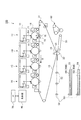
図1は、本発明の実施形態における画像形成装置100を示した概略構成図である。
同図に示す画像形成装置100は、一般にタンデム型と呼ばれる中間転写方式の画像形成装置である。この画像形成装置100には、電子写真方式により各色成分のトナー像が形成される複数の画像形成ユニット1Y,1M,1C,1Kが設けられている。
Hereinafter, embodiments of the present invention will be described in detail with reference to the accompanying drawings.
FIG. 1 is a schematic configuration diagram illustrating an
An
また、画像形成装置100には、各画像形成ユニット1Y,1M,1C,1Kにより形成された各色成分トナー像を中間転写ベルト15に順次転写(一次転写)させる一次転写部10が設けられている。さらに、画像形成装置100には、中間転写ベルト15上に転写された重畳トナー画像を用紙50に一括転写(二次転写)させる二次転写部20が設けられている。
Further, the
また、二次転写されたトナー像を用紙50上に定着させる定着装置60が設けられている。さらに、プログラム制御されたCPUにより構成され、画像形成装置100内の各装置(各部)を制御する制御部40が設けられている。また、表示パネルなどにより構成されユーザからの情報を受け付けるとともにユーザに対して情報を表示するUI(User Interface)70が設けられている。
In addition, a
画像形成部の一部として機能する画像形成ユニット1Y,1M,1C,1Kの各々には、次のような電子写真用デバイスが設けられている。まず、矢印A方向に回転する感光体ドラム11の周囲に、感光体ドラム11を帯電する帯電器12が設けられている。また、感光体ドラム11上に静電潜像を書込むレーザ露光器13(図中露光ビームを符号Bmで示す)が設けられている。
Each of the
さらに、各色成分トナーが収容され感光体ドラム11上の静電潜像をトナーにより可視像化する現像器14が設けられている。また、感光体ドラム11上に形成された各色成分トナー像を一次転写部10にて中間転写ベルト15に転写する一次転写ロール16が設けられている。また、感光体ドラム11上の残留トナーを除去するドラムクリーナ17が設けられている。
Further, a developing
中間転写ベルト15は、定速性に優れたモータ(図示せず)により駆動される駆動ロール31によって図1に示す矢印B方向に予め定められた速度で循環駆動する。一次転写部10は、中間転写ベルト15を挟んで感光体ドラム11に対向配置される一次転写ロール16を含んで構成されている。そして、各々の感光体ドラム11上のトナー像が中間転写ベルト15に順次、静電吸引され、中間転写ベルト15上に重畳されたトナー像が形成される。
The
二次転写部20は、中間転写ベルト15のトナー像保持面側に配置される二次転写ロール22と、バックアップロール25とを含んで構成される。二次転写ロール22は中間転写ベルト15を挟んでバックアップロール25に圧接配置されている。さらに二次転写ロール22は、接地されるとともに、二次転写ロール22とバックアップロール25との間に二次転写バイアスが形成され、二次転写部20に搬送される用紙50上にトナー像が二次転写される。
The
画像形成装置100の基本的な作像プロセスについて説明する。
画像形成装置100では、図示しない画像読取装置等から画像データが出力される。そして、この画像データは図示しない画像処理装置により画像処理が施され、Y、M、C、Kの4色の色材階調データに変換され、レーザ露光器13に出力される。
A basic image forming process of the
In the
レーザ露光器13では、入力された色材階調データに応じて、例えば半導体レーザから出射された露光ビームBmを画像形成ユニット1Y,1M,1C,1Kの各々の感光体ドラム11に照射する。各感光体ドラム11では、帯電器12によって表面が帯電された後、レーザ露光器13によって表面が走査露光され、静電潜像が形成される。そして現像器14により感光体ドラム11上にトナー像が形成された後、このトナー像は、各感光体ドラム11と中間転写ベルト15とが接触する一次転写部10において、中間転写ベルト15上に転写される。
The
トナー像が中間転写ベルト15の表面に一次転写された後、中間転写ベルト15の移動によりトナー像が二次転写部20に搬送される。二次転写部20では、二次転写ロール22が中間転写ベルト15を介してバックアップロール25に押圧される。このとき、第1用紙収容部53や第2用紙収容部54から搬送ロール52等により搬送された用紙50が、中間転写ベルト15と二次転写ロール22との間に挟み込まれる。
After the toner image is primarily transferred onto the surface of the
そして、中間転写ベルト15上に保持された未定着のトナー像は、二次転写部20において、用紙50上に一括して静電転写される。その後、トナー像が静電転写された用紙50は、中間転写ベルト15から剥離された後、二次転写ロール22よりも用紙搬送方向下流側に設けられた搬送ベルト55へ搬送される。そして搬送ベルト55は、用紙50を定着装置60まで搬送する。
The unfixed toner image held on the
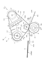
図2は、定着装置60の側断面図である。
定着装置60は、定着ベルト610を備える定着ベルトモジュール61と、定着ベルトモジュール61に押し当てられる押し当て部材の一例としての加圧ロール62とにより主要部が構成されている。この定着装置60では、定着ベルトモジュール61と加圧ロール62との接触部に、用紙50を加圧および加熱し用紙50にトナー像を定着させるニップ部Nが形成される。
FIG. 2 is a side sectional view of the fixing
The fixing
さらに説明すると、この定着装置60では、定着ベルト610の外周面610Aに対して加圧ロール62の外周面(外面)62Aの一部が押し当てられ、この一部の押し当てが行われている箇所に、ニップ部Nが形成される。付言すると、この一部の押し当てが行われている箇所には、トナー像が形成された用紙50が加圧および加熱されながら通過する通過部が形成される。
More specifically, in the fixing
なお、ニップ部Nに進入する用紙50には、トナー像が形成されたトナー像形成面51が存在するが、本実施形態では、このトナー像形成面51が図中上方を向いた状態で、ニップ部Nへの用紙50の進入が行われる。これにより、本実施形態では、トナー像形成面51側が定着ベルト610に接触する。
また、本実施形態では、加圧ロール62が不図示のモータにより回転駆動され、定着ベルト610がこの加圧ロール62に従動して回転する。さらに、加圧ロール62は、図中矢印2Xで示すように、定着ベルトモジュール61に対し進退可能に設けられている。
The paper 50 entering the nip portion N has a toner
In the present embodiment, the
定着ベルト610は、無端状に形成され、回転する加圧ロール62から駆動力を受け図中矢印2A方向に回転駆動(循環移動)を行う。
また、定着ベルト610は、例えば、ポリイミド樹脂で形成されたベース層と、ベース層の表面側(外周面側)に積層されたシリコーンゴムからなる弾性体層と、さらに弾性体層上に被覆されPFA(テトラフルオロエチレン−ペルフルオロアルキルビニルエーテル共重合体樹脂)等により形成された剥離層とで構成される。
The fixing
Further, the fixing
さらに、定着ベルトモジュール61には、回転可能に設けられ、内側から定着ベルト610を張架する第1張架ロール612が設けられている。また、定着ベルト610の移動方向において、第1張架ロール612よりも上流側には、同じく定着ベルト610を内側から張架する第2張架ロール613が設けられている。さらに、定着ベルト610の内側には、第2張架ロール613の変位(ステアリング)を行う変位手段の一例としてのステアリング機構614が設けられている。
Further, the fixing
ここで、本実施形態では、ステアリング機構614によって、第2張架ロール613が変位し(傾き)、これに伴い、定着ベルト610の幅方向に定着ベルト610が移動する。これにより、本実施形態では、定着ベルト610の幅方向における定着ベルト610の位置が調整されるようになり、予め定められた意図した経路に沿って定着ベルト610が移動するようになる。
Here, in the present embodiment, the
また、本実施形態では、定着ベルト610を挟み加圧ロール62の対向位置に、加圧ロール62からの荷重を受ける荷重受け部材615が設けられている。本実施形態では、加圧ロール62と荷重受け部材615とによって、用紙50が両側から挟まれ用紙50に対して圧力が加えられる。
さらに、本実施形態では、第1張架ロール612、第2張架ロール613、および、荷重受け部材615の内部に、これらを加熱するヒータ616が設けられている。ここで、このヒータ616は、例えばハロゲンヒータにより構成される。
In the present embodiment, a
Furthermore, in the present embodiment, a
さらに、本実施形態では、定着ベルト610の内側に対して、オイルなどの潤滑剤を供給する第1潤滑剤供給部材617A、第2潤滑剤供給部材617Bが設けられている。第1潤滑剤供給部材617Aは、定着ベルト610の移動方向において、第1張架ロール612よりも上流側に、第2張架ロール613よりも下流側に配置されている。また、第2潤滑剤供給部材617Bは、定着ベルト610の移動方向において、第1張架ロール612よりも下流側に、荷重受け部材615よりも上流側に配置されている。
Further, in the present embodiment, a first
また、本実施形態では、用紙50の搬送方向において、ニップ部Nよりも上流側に、ニップ部Nへ搬送される用紙50の案内を行う第1用紙案内部材618が設けられている。この第1用紙案内部材618は、上面618Aを用いて用紙50を下方から支持し、ニップ部Nへの用紙50の案内を行う。
また、ニップ部Nよりも下流側には、ニップ部Nから搬送されてきた用紙50の下流側への案内を行う第2用紙案内部材619が設けられている。この第2用紙案内部材619も、上面619Aを用いて用紙50を下方から支持し、下流側への用紙50の案内を行う。
In the present embodiment, a first
Further, on the downstream side of the nip portion N, a second
さらに、本実施形態では、ニップ部Nよりも上流側に、上流側から搬送されてきた用紙50が通る、断面形状が三角形の上流側用紙通過領域701が形成されている。
上流側用紙通過領域701は、定着ベルト610よりも図中下方に、且つ、加圧ロール62の外周面62Aよりも図中上方に配置されている。さらに説明すると、本実施形態では、定着ベルト610のうちの、ニップ部Nよりも上流側に位置する部分と、加圧ロール62の外周面62Aのうちの、ニップ部Nよりも上流側に位置する部分とにより囲まれた領域が、上流側用紙通過領域701となっている。
Further, in the present embodiment, an upstream
The upstream
また、本実施形態では、ニップ部Nよりも下流側に、ニップ部Nから排出された用紙50が通る、断面形状が三角形の下流側用紙通過領域702が形成されている。
この下流側用紙通過領域702も、上流側用紙通過領域701と同様、定着ベルト610よりも図中下方に、且つ、加圧ロール62の外周面62Aよりも図中上方に配置されている。さらに説明すると、定着ベルト610のうちの、ニップ部Nよりも下流側に位置する部分と、加圧ロール62の外周面62Aのうちの、ニップ部Nよりも下流側に位置する部分とにより囲まれた領域が、下流側用紙通過領域702となっている。
Further, in the present embodiment, a downstream
Similarly to the upstream
図3は、図2における矢印III方向から定着ベルトモジュール61を眺めた場合の図である。
本実施形態では、上記のとおり、第2張架ロール613を変位させるステアリング機構614(図2参照)が設けられており、このステアリング機構614は、図3に示すように、第2張架ロール613の軸方向における中央部613Aを中心に第2張架ロール613を回転(揺動)させる。これにより、第2張架ロール613の軸方向における何れか一端部側に向かって定着ベルト610が移動するようになり、これに伴い、定着ベルト610の幅方向における位置が変化する。
FIG. 3 is a view when the fixing
In the present embodiment, as described above, the steering mechanism 614 (see FIG. 2) for displacing the
なお、本実施形態では、第2張架ロール613の軸方向における中央部613Aを中心に第2張架ロール613を回転(揺動)させる構成を採用しているが、第2張架ロール613の軸方向における一端部を固定し、他端部側を揺動させる構成を採用してもよい。
In the present embodiment, a configuration is adopted in which the
また、本実施形態では、変位させる対象(ステアリングを行う対象)を第2張架ロール613としたが、第1張架ロール612を変位させてもよい。但し、次に説明するとおり、第1張架ロール612ではなく第2張架ロール613を変位させた方が、用紙50上のトナー像の乱れが抑制されるようになる。
In the present embodiment, the object to be displaced (the object to be steered) is the
ここで、本実施形態では、図2にて示したとおり、ニップ部Nよりも上流側に、用紙50が通る上流側用紙通過領域701が存在する。ここで、この上流側用紙通過領域701を用紙50が通過する際に、用紙50のトナー像形成面51(図2参照)が定着ベルト610に接触すると、トナー像に乱れが生じるおそれがある。付言すると、ニップ部Nに進入する前のトナー像は未定着状態にあり、トナー像形成面51が定着ベルト610に接触すると、トナー像に乱れが生じるおそれがある。
Here, in the present embodiment, as shown in FIG. 2, an upstream side
このような状況下において、第1張架ロール612を変位させてしまうと(ステアリングすると)、上流側用紙通過領域701が狭まり、用紙50のトナー像形成面51が定着ベルト610に接触する可能性が高まる。
Under such circumstances, if the
詳細に説明すると、第1張架ロール612を変位させると、図2の矢印2Dに示すような動きを第1張架ロール612の端部は行い、これに伴い、定着ベルト610が用紙50の搬送経路に接近し、上流側用紙通過領域701が狭まる。そしてこの場合、上記のとおり、トナー像形成面51が定着ベルト610に接触する可能性が高まる。一方で、第2張架ロール613を変位させる構成を採用した場合には、上流側用紙通過領域701が狭まることが抑制され、トナー像形成面51の定着ベルト610への接触が起きにくくなる。
More specifically, when the
さらに、本実施形態では、上流側用紙通過領域701と下流側用紙通過領域702とを比較した場合に、上流側用紙通過領域701よりも下流側用紙通過領域702の方が、大きくなっている。
Furthermore, in the present embodiment, when the upstream
図2を参照してさらに説明すると、上流側用紙通過領域701は、用紙50の搬送方向上流側に向かうに従い図中高さ方向における寸法が大きくなる。さらに説明すると、上流側用紙通過領域701では、定着ベルト610と加圧ロール62の外周面62Aとの間に形成された間隙が、用紙50の搬送方向上流側に向かうに従い拡がるようになる。
さらに説明すると、本実施形態では、加圧ロール62の外周面62Aのうち、ニップ部Nよりも上流側に位置する上流側部分62Bは、定着ベルト610の外周面610Aとの間に間隙705(以下、「上流側間隙705」と称する)を有して形成されるとともに、上流側に向かうに従いこの上流側間隙705が拡がるように形成されている。
Further description will be made with reference to FIG. 2. The upstream
More specifically, in the present embodiment, of the outer
また、下流側用紙通過領域702は、用紙50の搬送方向下流側に向かうに従い図中高さ方向における寸法が大きくなる。さらに説明すると、下流側用紙通過領域702では、定着ベルト610と加圧ロール62の外周面62Aとの間に形成された間隙が、用紙50の搬送方向下流側に向かうに従い拡がるようになる。
さらに説明すると、本実施形態では、加圧ロール62の外周面62Aのうち、ニップ部Nよりも下流側に位置する下流側部分62Cは、定着ベルト610の外周面610Aとの間に間隙706(以下、「下流側間隙706」と称する)を有して形成されるとともに、下流側に向かうに従いこの下流側間隙706が拡がるように形成されている。
Further, the downstream
More specifically, in the present embodiment, of the outer
ここで、上流側用紙通過領域701および下流側用紙通過領域702のいずれにおいても、定着ベルト610と加圧ロール62の外周面62Aとの間に形成された間隙は、用紙搬送方向上流側ないし用紙搬送方向下流側に向かうに従い拡がるが、本実施形態では、この拡がりの度合いが異なっている。
Here, in both the upstream
具体的には、下流側用紙通過領域702における拡がりの度合いの方が、上流側用紙通過領域701における拡がりの度合いよりも大きくなっている。そして、本実施形態では、この拡がりの度合いの違いを考慮し、拡がりの度合いが大きい下流側用紙通過領域702が位置する側の張架ロールを変位させる構成としている。即ち、第2張架ロール613を変位させる構成としている。
Specifically, the degree of expansion in the downstream
付言すると、本実施形態では、下流側間隙706の拡がり具合の方が、上流側間隙705の拡がり具合よりも大きくなっており、拡がり具合の大きい下流側間隙706側に位置する張架ロール(第2張架ロール613)を変位させる構成としている。さらに説明すると、本実施形態では、張架ロールの変位(ステアリング)を行うと、定着ベルト610の一部が加圧ロール62の外周面62Aに接近するが、この接近が、下流側間隙706側にて起こる構成となっている。
In addition, in this embodiment, the degree of expansion of the
上記にて説明したとおり、張架ロールの変位を行うと、これに伴い、定着ベルト610が加圧ロール62の外周面62Aに接近する。そして、このように、定着ベルト610が加圧ロール62の外周面62Aに接近すると、用紙50が通過していく領域である、上流側用紙通過領域701あるいは下流側用紙通過領域702が狭まるようになる。
そして、このように、上流側用紙通過領域701あるいは下流側用紙通過領域702が狭まると、本来予定していた用紙50の搬送性能が、異なる搬送性能に変化してしまうおそれがある。
As described above, when the tension roll is displaced, the fixing
As described above, when the upstream
その一方で、上流側用紙通過領域701あるいは下流側用紙通過領域702が狭まったとしても、狭まる前の状態における領域の大きさが大きければ、搬送性能の変化を招いてしまうものの、この変化の程度を抑えられるようになる。このため、本実施形態では、拡がりの度合いがより大きい下流側用紙通過領域702側に位置する第2張架ロール613を変位させる構成としている。
On the other hand, even if the upstream side
定着装置60の構成についてさらに説明する。
本実施形態のように、第2張架ロール613を変位させる構成の場合、第1張架ロール612を変位させる構成に比べ、定着ベルト610の幅方向への移動が起こりやすくなる。
付言すると、第2張架ロール613を変位させる場合、第1張架ロール612を変位させる場合に比べて、より少ない変位量で、定着ベルト610の移動を行えるようになる。さらに説明すると、第2張架ロール613を変位させる場合、第1張架ロール612を変位させる場合に比べ、張架ロールの変位に対する定着ベルト610の感度が高まるようになる。
The configuration of the fixing
In the configuration in which the
In addition, when the
ここで、第2張架ロール613は、ニップ部Nを通過した後からみて最上流に位置する張架ロールとなっている。付言すると、本実施形態では、ニップ部Nを通過した定着ベルト610が最初に達する張架ロールが第2張架ロール613となっている。この結果、第2張架ロール613は、定着ベルト610のうちの最も温度が下がっている部分を張架することになる。付言すると、本実施形態では、ニップ部Nにて、定着ベルト610の熱が用紙50に奪われるため、ニップ部Nを通過した直後の定着ベルト610は温度が低い状態にあり、本実施形態では、定着ベルト610の温度が低い部分が第2張架ロール613に達する。
Here, the
ここで、定着ベルト610の温度が低い場合、温度が高い場合に比べ、潤滑剤の粘度が増加し、これに伴い、定着ベルト610と第2張架ロール613との間で滑りが生じにくくなる。そしてこの場合、第2張架ロール613の動き(変位)に定着ベルト610がより追従するようになり、より少ない変位量(ステアリング量)で、定着ベルト610の移動が起きるようになる。
Here, when the temperature of the fixing
定着装置60の構成についてさらに説明する。
本実施形態では、第2張架ロール613と定着ベルト610との間における摩擦係数(静摩擦係数)の方を、第1張架ロール612と定着ベルト610との間における摩擦係数よりも大きくしている。これにより、第2張架ロール613を変位させた際の定着ベルト610の移動を起きやすくしている。
The configuration of the fixing
In this embodiment, the coefficient of friction (static friction coefficient) between the
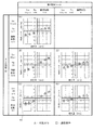
図4は、張架ロール(第1張架ロール612および第2張架ロール613)と定着ベルト610との間の摩擦係数と、定着ベルト610の移動量との関係を示した図である。
FIG. 4 is a diagram illustrating the relationship between the friction coefficient between the tension rolls (the
図4(A)は、第2張架ロール613と定着ベルト610との間における摩擦係数(第2張架ロール613の軸方向における摩擦係数)(以下、「第2摩擦係数」と称する)を0.19とし、第1張架ロール612と定着ベルト610との間における摩擦係数(第1張架ロール612の軸方向における摩擦係数)(以下、「第1摩擦係数」と称する)を0.17とした場合の、定着ベルト610の移動量を示した図である。
付言すると、第2張架ロール613の方が第1張架ロール612よりも定着ベルト610に対して滑りにくくなっている場合における、定着ベルト610の移動量を示した図である。
FIG. 4A shows a friction coefficient between the
In addition, it is a diagram showing the amount of movement of the fixing
なお、図4(A)における条件では、第2張架ロール613、第1張架ロール612のRa(算術平均粗さ)、Sm(凹凸の平均間隔)を測定したところ、第2張架ロール613のRa、Sm、第1張架ロール612のRa、Smは、それぞれ、0.49、55μm、0.77、67μmとなっていた。
4A, when the Ra (arithmetic mean roughness) and Sm (average interval of unevenness) of the
この条件では、図4(A)に示すように、第2張架ロール613の変位量(傾き量)に応じ、定着ベルト610の移動量が増えることが分かる。但し、この条件では、第1摩擦係数と第2摩擦係数との差が小さく、後述する条件に比べ、定着ベルト610の移動量は小さくなっている。
Under this condition, as shown in FIG. 4A, it can be seen that the movement amount of the fixing
なお、図4(A)、および、以下に説明する図4(B)〜(E)の各々では、(1)外乱を定着装置60に与えた状態における定着ベルト610の移動量、および、(2)外乱を定着装置60に与えていない状態における定着ベルト610の移動量、の二つの移動量を示している。
ここで、図4(A)、および、図4(B)〜(E)の各々では、外乱を与えた場合の移動量を図中三角で示し、外乱を与えていない場合の移動量を図中四角で示している。なお、外乱の付与は、加圧ロール62の軸心を定着ベルト610の幅方向に対して傾けた状態で加圧ロール62を定着ベルト610に押し当てることで行っている。
4A and FIGS. 4B to 4E described below, (1) the amount of movement of the fixing
Here, in each of FIG. 4A and FIGS. 4B to 4E, the movement amount when the disturbance is given is indicated by a triangle in the figure, and the movement amount when the disturbance is not given is illustrated. Shown in the middle square. The disturbance is applied by pressing the
図4(B)は、第2摩擦係数を0.19とし、第1摩擦係数を0.15とした場合の定着ベルト610の移動量を示した図である。付言すると、第2張架ロール613の方が第1張架ロール612よりも定着ベルト610に対して滑りにくくなっており、且つ、図4(A)に示した条件に比べ、定着ベルト610に対し第1張架ロール612がさらに滑りやすくなっている場合の、定着ベルト610の移動量を示した図である。なお、この条件では、第2張架ロール613のRa、Sm、第1張架ロール612のRa、Smは、それぞれ、0.49、55μm、0.9、90μmとなっていた。
FIG. 4B shows the amount of movement of the fixing
この条件の場合、図4(A)にて示した条件に比べ、第1張架ロール612に対する定着ベルト610の滑りが起きやすくなり、図4(A)にて示した条件に比べ、定着ベルト610の幅方向に定着ベルト610が動きやすくなる。そしてこの場合、図4(B)に示すように、図4(A)にて示した条件に比べ、グラフの傾きが大きくなり、第2張架ロール613の変位に対する定着ベルト610の感度が高まるようになる。
In the case of this condition, compared to the condition shown in FIG. 4A, the fixing
図4(C)は、第2摩擦係数を0.19とし、第1摩擦係数を0.1とした場合の定着ベルト610の移動量を示した図である。付言すると、第2張架ロール613の方が第1張架ロール612よりも定着ベルト610に対して滑りにくくなっており、且つ、図4(B)に示した条件に比べ、定着ベルト610に対し第1張架ロール612がさらに滑りやすくなっている場合の、定着ベルト610の移動量を示した図である。なお、この条件では、第2張架ロール613のRa、Sm、第1張架ロール612のRa、Smは、それぞれ、0.49、55μm、0.86、150μmとなっていた。
FIG. 4C shows the amount of movement of the fixing
この条件では、図4(C)に示すように、また、図4(B)にて示した条件と同様に、第1張架ロール612に対する定着ベルト610の滑りが起きやすくなり、図4(A)にて示した条件に比べ、定着ベルト610の幅方向に定着ベルト610が動きやすくなる。そしてこの場合、図4(B)にて示した条件と同様、グラフの傾きが大きくなり、第2張架ロール613の変位に対する定着ベルト610の感度が高まるようになる。
Under this condition, as shown in FIG. 4C, and similarly to the condition shown in FIG. 4B, the fixing
但し、図4(C)に示す条件では、第1張架ロール612に対する定着ベルト610の滑りが起きやすくなっており、これにより、外乱の影響を受けやすくなってしまっている。
ここで、上記のように、加圧ロール62が傾けられて配置されるなど、定着装置60に対して外乱が与えられると、この外乱によって、定着ベルト610の幅方向へ定着ベルト610が移動しうるが、第1張架ロール612と定着ベルト610との間で滑りが起きにくいと、定着ベルト610に抗力が付与される形なり、外乱に対する抵抗力が増す。
However, under the conditions shown in FIG. 4C, the fixing
Here, as described above, when a disturbance is applied to the fixing
一方で、図4(C)における条件のように、第1張架ロール612に対し定着ベルト610が滑りやすいと、外乱に対する抵抗力が小さくなる。そして、この場合は、図4(C)の符号4Xに示すように、定着ベルト610の移動量が、第2張架ロール613の変位量に比例しにくくなる状況が発生しうる。付言すると、第2張架ロール613を変位させて定着ベルト610を移動させようとしても、定着ベルト610が移動しないことが起こりうる。
On the other hand, when the fixing
次に、第2摩擦係数の方が第1摩擦係数よりも小さく、第2張架ロール613の方が第1張架ロール612よりも定着ベルト610に対して滑りやすくなっている場合の、定着ベルト610の移動量を説明する。
Next, fixing is performed when the second friction coefficient is smaller than the first friction coefficient, and the
図4(D)は、第2摩擦係数を0.1とし、第1摩擦係数を0.15とした場合の定着ベルト610の移動量を示した図である。なお、この条件では、第2張架ロール613のRa、Sm、第1張架ロール612のRa、Smは、それぞれ、0.47、150μm、0.9、90μmとなっていた。
FIG. 4D shows the amount of movement of the fixing
図4(D)における条件では、第2張架ロール613に対する定着ベルト610の滑りが起きやすくなり、第2張架ロール613に対して定着ベルト610が追従しにくくなる。そしてこの場合は、図4(D)に示すように、グラフの傾きが小さくなり、第2張架ロール613の変位に対する定着ベルト610の感度が小さくなってしまう。
4D, the fixing
図4(E)は、第2摩擦係数を0.1とし、第1摩擦係数を0.1とした場合の定着ベルト610の移動量を示した図である。
図4(E)における条件では、第2張架ロール613に対する定着ベルト610の滑りが起きやすく、また、第1摩擦係数も0.1とさらに小さくなり、第1張架ロール612に対する定着ベルト610の滑りも起きやすくなっている。
この場合、第2張架ロール613に対して定着ベルト610が追従しにくくなり、また、外乱に対する抵抗力も小さくなる。そして、この場合、図4(D)の場合と同様、グラフの傾きが小さくなり、第2張架ロール613の変位に対する定着ベルト610の感度が小さくなる。
FIG. 4E is a diagram showing the amount of movement of the fixing
4E, the fixing
In this case, the fixing
ここで、図4にて示した結果をまとめると、図4(B)における条件が、第2張架ロール613の変位に対する定着ベルト610の感度を高められるようになり、また、外乱に対する抵抗力が付与されるようになった。また、発明者が行った他の実験を含めて検討したところ、第2張架ロール613のRaを0.3〜0.5、Smを40〜60μm、第1張架ロール612(他の張架ロール)のRaを0.7〜0.9、Smを80〜100μmとすることで、定着ベルト610の感度を高められるようになり、また、外乱に対する抵抗力が付与されるようになった。
Here, when the results shown in FIG. 4 are summarized, the condition in FIG. 4B can increase the sensitivity of the fixing
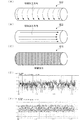
さらに、上記では説明を省略したが、本実施形態では、第2張架ロール613を切削加工により形成している。この際、本実施形態では、図5(第2張架ロール613の詳細を説明するための図)の(A)に示すように、切削加工方向が、円柱状に形成された第2張架ロール613の周方向に沿うように、切削加工を行っている。付言すると、切削加工を行う際の切削工具の移動方向を第2張架ロール613の周方向としている。
Furthermore, although description was abbreviate | omitted above, in this embodiment, the
ここで、例えば、図5(B)に示すように、切削加工方向が第2張架ロール613の軸方向に沿うように切削加工を行うと、定着ベルト610と第2張架ロール613との間でスリップが発生した際に、定着ベルト610の摩耗が発生しやすくなる。また、例えば、図5(C)に示すように、第2張架ロール613の表面に対して研磨加工を行う態様もあるが、この場合は、第2張架ロール613の表面がヤスリのようになり、同様に、定着ベルト610の摩耗が発生しやすくなる。
Here, for example, as shown in FIG. 5B, if the cutting process is performed so that the cutting direction is along the axial direction of the
一方で、本実施形態のように、切削加工方向を、第2張架ロール613の周方向とした場合には、切削加工方向を第2張架ロール613の軸方向とした場合や、研磨加工を第2張架ロール613に対して行う場合に比べ、定着ベルト610の摩耗の発生が抑制される。
なお、図5(D)は、第2張架ロール613に対して研磨加工を行った際の、第2張架ロール613の表面の断面形状(軸方向に沿った面における断面形状)を示し、図5(E)は、第2張架ロール613の周方向に沿って切削加工を行った際の、第2張架ロール613の表面の断面形状を示している。
On the other hand, when the cutting direction is the circumferential direction of the
FIG. 5D shows a cross-sectional shape (a cross-sectional shape in a plane along the axial direction) of the surface of the
ここで、定着ベルト610の摩耗が発生すると摩耗粉が発生する。そして、この場合、この摩耗粉が荷重受け部材615と定着ベルト610の内周面との間に入り込み、荷重受け部材615から定着ベルト610に対して作用する摺動抵抗が増大する。また、摩耗粉が発生すると、この摩耗粉に起因して、形成される画像の質の低下を招きうる。本実施形態のように、第2張架ロール613の周方向に沿って切削加工を行うと、摩耗粉が減り、摩耗粉に起因するこれらの不具合が生じにくくなる。
Here, when wear of the fixing
(その他)
本実施形態の定着装置60では、図2に示すように、定着ベルト610が第1張架ロール612に巻き付いている長さであって第1張架ロール612の周方向における長さであるラップ長(図2の符号L1参照、以下、「第1ラップ長L1」と称する)の方が、定着ベルト610が第2張架ロール613に巻き付いている長さであって第2張架ロール613の周方向における長さであるラップ長(図2の符号L2参照、以下、「第2ラップ長L2」と称する)の方が大きくなっている。
(Other)
In the fixing
ところで、この長さ関係は一例であり、第2ラップ長L2の方を第1ラップ長L1よりも大きくしてもよい。このように、第2ラップ長L2の方を第1ラップ長L1よりも大きくした場合、第2張架ロール613と定着ベルト610との接触面積が増加するようになり、これにより、第2張架ロール613の変位(ステアリング)に対して定着ベルト610がより追従するようになる。付言すると、この場合、第2張架ロール613の変位に対する定着ベルト610の感度が高まるようになる。
By the way, this length relationship is an example, and the second wrap length L2 may be larger than the first wrap length L1. As described above, when the second wrap length L2 is longer than the first wrap length L1, the contact area between the
また、上記では、張架ロールとして、第1張架ロール612および第2張架ロール613の2本の張架ロールを設けた場合を一例に説明したが、3本以上の張架ロールを設けるようにしてもよい。また、張架ロールは、定着ベルト610の内側における配置に限らず、複数設けられた張架ロールの一部を定着ベルト610の外側に配置し、外側から定着ベルト610を張架するようにしてもよい。
In the above description, the case where the two tension rolls, the
また、第1張架ロール612のRaを第2張架ロール613(他の張架ロール)のRaよりも大きくすることも好ましい。この場合、第2張架ロール613(他の張架ロール)のRaの方が第1張架ロール612のRaよりも大きい場合に比べ、第1張架ロール612の外周面上により多くの潤滑剤が保持されるようになる。そしてこの場合、ニップ部Nのすぐ上流側に、より多くの潤滑剤が保持された形となり、荷重受け部材615と定着ベルト610との摺動部に対してより多くの潤滑剤が供給されるようになる。
Moreover, it is also preferable to make Ra of the
1Y,1M,1C,1K…画像形成ユニット、60…定着装置、62…加圧ロール、62A…外周面(外面)、62B…上流側部分、62C…下流側部分、100…画像形成装置、610…定着ベルト、610A…外周面、612…第1張架ロール、613…第2張架ロール、614…ステアリング機構、705…上流側間隙、706…下流側間隙、N…ニップ部 1Y, 1M, 1C, 1K ... image forming unit, 60 ... fixing device, 62 ... pressure roll, 62A ... outer peripheral surface (outer surface), 62B ... upstream portion, 62C ... downstream portion, 100 ... image forming device, 610 ... fixing belt, 610A ... outer peripheral surface, 612 ... first tension roll, 613 ... second tension roll, 614 ... steering mechanism, 705 ... upstream gap, 706 ... downstream gap, N ... nip portion
Claims (7)
外面を有し、前記ベルト部材の外周面に当該外面の一部が押し当てられ、画像が形成された記録材が加圧されながら通過する通過部を当該ベルト部材との間に形成する押し当て部材と、
前記ベルト部材を張架する張架部材と、
前記張架部材を変位させる変位手段と、
を備え、
前記押し当て部材の前記外面のうち、前記通過部よりも記録材通過方向における上流側に位置する上流側部分は、前記ベルト部材の前記外周面との間に上流側間隙を有して形成されるとともに、上流側に向かうに従い当該上流側間隙が拡がるように形成され、
前記押し当て部材の前記外面のうち、前記通過部よりも記録材通過方向における下流側に位置する下流側部分は、前記ベルト部材の前記外周面との間に下流側間隙を有して形成されるとともに、下流側に向かうに従い当該下流側間隙が拡がるように形成され、
前記上流側間隙の拡がり具合と前記下流側間隙の拡がり具合とが異なっており、一方の間隙の拡がり具合の方が他方の間隙の広がり具合よりも大きくなっており、
前記変位手段による前記張架部材の変位に伴い、前記ベルト部材の一部が前記押し当て部材の前記外面に接近し、
前記ベルト部材の前記一部の前記外面への接近が、前記一方の間隙側および前記他方の間隙側のうちの、当該一方の間隙側にて起こるように構成された定着装置。 A belt member provided in a circulating manner;
A pressing portion that has an outer surface, a part of the outer surface is pressed against the outer peripheral surface of the belt member, and a passing portion through which the recording material on which the image is formed is pressed is formed between the belt member and the belt member. Members,
A tension member that stretches the belt member;
Displacement means for displacing the tension member;
With
Of the outer surface of the pressing member, an upstream portion located upstream of the passage portion in the recording material passage direction is formed with an upstream gap between the outer peripheral surface of the belt member. And the upstream gap is formed to widen toward the upstream side,
Of the outer surface of the pressing member, a downstream portion located downstream of the passing portion in the recording material passing direction is formed with a downstream gap between the outer peripheral surface of the belt member. And is formed so that the downstream gap widens toward the downstream side,
The extent of the upstream gap is different from the extent of the downstream gap, and the extent of the one gap is greater than the extent of the other gap,
Along with the displacement of the tension member by the displacement means, a part of the belt member approaches the outer surface of the pressing member,
The fixing device configured to cause the part of the belt member to approach the outer surface on the one gap side of the one gap side and the other gap side.
前記ベルト部材の前記一部の前記外面への接近が、前記下流側間隙側にて起こるように構成された請求項1に記載の定着装置。 The extent of expansion of the downstream gap is larger than the extent of expansion of the upstream gap,
The fixing device according to claim 1, wherein the part of the belt member approaches the outer surface on the downstream gap side.
前記他の張架部材と前記ベルト部材との接触部にて生じる第1の摩擦力であって当該他の張架部材の軸方向における当該第1の摩擦力と、前記変位手段により変位する前記張架部材と前記ベルト部材との接触部にて生じる第2の摩擦力であって当該張架部材の軸方向における当該第2の摩擦力とを比較した場合に、当該第2の摩擦力の方が当該第1の摩擦力よりも大きくなるように構成されていることを特徴とする請求項1乃至4の何れかに記載の定着装置。 It further includes another tension member that stretches the belt member,
The first frictional force generated at the contact portion between the other tension member and the belt member, the first frictional force in the axial direction of the other tension member, and the displacement by the displacement means When the second frictional force generated at the contact portion between the tension member and the belt member and compared with the second frictional force in the axial direction of the tension member, the second frictional force The fixing device according to claim 1, wherein the fixing device is configured to be larger than the first frictional force.
外面を有し、前記ベルト部材の外周面に当該外面の一部が押し当てられ、画像が形成された記録材が加圧されながら通過する通過部を当該ベルト部材との間に形成する押し当て部材と、
前記ベルト部材を張架する張架部材と、
前記張架部材を変位させる変位手段と、
を備え、
前記押し当て部材の前記外面のうち、前記通過部よりも記録材通過方向における上流側に位置する上流側部分は、前記ベルト部材の前記外周面との間に上流側間隙を有して形成され、
前記押し当て部材の前記外面のうち、前記通過部よりも記録材通過方向における下流側に位置する下流側部分は、前記ベルト部材の前記外周面との間に下流側間隙を有して形成され、
前記変位手段による前記張架部材の変位に伴い、前記ベルト部材の一部が前記押し当て部材の前記外面に接近し、
前記ベルト部材の前記一部の前記外面への接近が、前記下流側間隙側にて起こるように構成された定着装置。 A belt member provided in a circulating manner;
A pressing portion that has an outer surface, a part of the outer surface is pressed against the outer peripheral surface of the belt member, and a passing portion through which the recording material on which the image is formed is pressed is formed between the belt member and the belt member. Members,
A tension member that stretches the belt member;
Displacement means for displacing the tension member;
With
Of the outer surface of the pressing member, an upstream portion located upstream of the passage portion in the recording material passage direction is formed with an upstream gap between the outer peripheral surface of the belt member. ,
Of the outer surface of the pressing member, a downstream portion located downstream of the passing portion in the recording material passing direction is formed with a downstream gap between the outer peripheral surface of the belt member. ,
Along with the displacement of the tension member by the displacement means, a part of the belt member approaches the outer surface of the pressing member,
A fixing device configured such that the part of the belt member approaches the outer surface on the downstream gap side.
前記画像形成部により記録材に形成された画像を当該記録材に定着する定着装置と、
を備え、
前記定着装置が、請求項1乃至6の何れかに記載の定着装置であることを特徴とする画像形成装置。 An image forming unit for forming an image on a recording material;
A fixing device for fixing the image formed on the recording material by the image forming unit to the recording material;
With
An image forming apparatus, wherein the fixing device is the fixing device according to claim 1.
Priority Applications (1)
| Application Number | Priority Date | Filing Date | Title |
|---|---|---|---|
| JP2013254527A JP6303464B2 (en) | 2013-12-09 | 2013-12-09 | Fixing apparatus and image forming apparatus |
Applications Claiming Priority (1)
| Application Number | Priority Date | Filing Date | Title |
|---|---|---|---|
| JP2013254527A JP6303464B2 (en) | 2013-12-09 | 2013-12-09 | Fixing apparatus and image forming apparatus |
Related Child Applications (1)
| Application Number | Title | Priority Date | Filing Date |
|---|---|---|---|
| JP2017243460A Division JP2018045255A (en) | 2017-12-20 | 2017-12-20 | Fixing device |
Publications (3)
| Publication Number | Publication Date |
|---|---|
| JP2015114393A true JP2015114393A (en) | 2015-06-22 |
| JP2015114393A5 JP2015114393A5 (en) | 2017-06-01 |
| JP6303464B2 JP6303464B2 (en) | 2018-04-04 |
Family
ID=53528261
Family Applications (1)
| Application Number | Title | Priority Date | Filing Date |
|---|---|---|---|
| JP2013254527A Active JP6303464B2 (en) | 2013-12-09 | 2013-12-09 | Fixing apparatus and image forming apparatus |
Country Status (1)
| Country | Link |
|---|---|
| JP (1) | JP6303464B2 (en) |
Cited By (3)
| Publication number | Priority date | Publication date | Assignee | Title |
|---|---|---|---|---|
| JP2018045255A (en) * | 2017-12-20 | 2018-03-22 | 富士ゼロックス株式会社 | Fixing device |
| JP2020052122A (en) * | 2018-09-25 | 2020-04-02 | 富士ゼロックス株式会社 | Fixation device and image formation apparatus |
| JP2021032910A (en) * | 2019-08-13 | 2021-03-01 | 富士ゼロックス株式会社 | Liquid application device, fixation device and image formation apparatus |
Citations (7)
| Publication number | Priority date | Publication date | Assignee | Title |
|---|---|---|---|---|
| JPH02157880A (en) * | 1988-12-12 | 1990-06-18 | Canon Inc | Image heating fixing device |
| JPH06118823A (en) * | 1992-10-06 | 1994-04-28 | Canon Inc | Endless belt drive |
| JPH06124123A (en) * | 1992-10-12 | 1994-05-06 | Bando Chem Ind Ltd | Belt drive |
| JP2009264447A (en) * | 2008-04-23 | 2009-11-12 | Ricoh Co Ltd | Travelling roller and its manufacturing method, and image forming device |
| JP2010217270A (en) * | 2009-03-13 | 2010-09-30 | Konica Minolta Business Technologies Inc | Fixing device and image forming apparatus |
| JP2012118339A (en) * | 2010-12-01 | 2012-06-21 | Fuji Xerox Co Ltd | Image forming apparatus and fixing device |
| JP2013218226A (en) * | 2012-04-12 | 2013-10-24 | Fuji Xerox Co Ltd | Belt driving device, fixing device, and image forming apparatus |
-
2013
- 2013-12-09 JP JP2013254527A patent/JP6303464B2/en active Active
Patent Citations (7)
| Publication number | Priority date | Publication date | Assignee | Title |
|---|---|---|---|---|
| JPH02157880A (en) * | 1988-12-12 | 1990-06-18 | Canon Inc | Image heating fixing device |
| JPH06118823A (en) * | 1992-10-06 | 1994-04-28 | Canon Inc | Endless belt drive |
| JPH06124123A (en) * | 1992-10-12 | 1994-05-06 | Bando Chem Ind Ltd | Belt drive |
| JP2009264447A (en) * | 2008-04-23 | 2009-11-12 | Ricoh Co Ltd | Travelling roller and its manufacturing method, and image forming device |
| JP2010217270A (en) * | 2009-03-13 | 2010-09-30 | Konica Minolta Business Technologies Inc | Fixing device and image forming apparatus |
| JP2012118339A (en) * | 2010-12-01 | 2012-06-21 | Fuji Xerox Co Ltd | Image forming apparatus and fixing device |
| JP2013218226A (en) * | 2012-04-12 | 2013-10-24 | Fuji Xerox Co Ltd | Belt driving device, fixing device, and image forming apparatus |
Cited By (5)
| Publication number | Priority date | Publication date | Assignee | Title |
|---|---|---|---|---|
| JP2018045255A (en) * | 2017-12-20 | 2018-03-22 | 富士ゼロックス株式会社 | Fixing device |
| JP2020052122A (en) * | 2018-09-25 | 2020-04-02 | 富士ゼロックス株式会社 | Fixation device and image formation apparatus |
| JP7172357B2 (en) | 2018-09-25 | 2022-11-16 | 富士フイルムビジネスイノベーション株式会社 | Fixing device and image forming device |
| JP2021032910A (en) * | 2019-08-13 | 2021-03-01 | 富士ゼロックス株式会社 | Liquid application device, fixation device and image formation apparatus |
| JP7342512B2 (en) | 2019-08-13 | 2023-09-12 | 富士フイルムビジネスイノベーション株式会社 | Liquid coating device, fixing device and image forming device |
Also Published As
| Publication number | Publication date |
|---|---|
| JP6303464B2 (en) | 2018-04-04 |
Similar Documents
| Publication | Publication Date | Title |
|---|---|---|
| JP5487833B2 (en) | Fixing apparatus and image forming apparatus | |
| JP6622542B2 (en) | Fixing apparatus and image forming apparatus | |
| JP6318592B2 (en) | Fixing apparatus and image forming apparatus | |
| US8364068B2 (en) | Fixing device and image forming apparatus | |
| JP6303464B2 (en) | Fixing apparatus and image forming apparatus | |
| JP6171563B2 (en) | Fixing apparatus and image forming apparatus | |
| US9098039B1 (en) | Roller-shaped rotator, fixing device, and image forming apparatus | |
| JP2011059590A (en) | Fixing device and image forming apparatus | |
| JP2010156818A (en) | Fixing device and image forming apparatus equipped therewith | |
| JP2008122849A (en) | Fixing device | |
| JP2009264447A (en) | Travelling roller and its manufacturing method, and image forming device | |
| JP2018045255A (en) | Fixing device | |
| JP2015094921A (en) | Fixing apparatus and image forming apparatus | |
| JP7380043B2 (en) | Fixing device and image forming device | |
| JP4794955B2 (en) | Image heating device | |
| JP2019101164A (en) | Fixing device | |
| JP2020154090A (en) | Fixing device and image forming apparatus | |
| JP2018084744A (en) | Fixing device | |
| JP7172357B2 (en) | Fixing device and image forming device | |
| JP2011145334A (en) | Fixing device and image forming apparatus | |
| JP6066001B1 (en) | Fixing apparatus and image forming apparatus | |
| JP2005227612A (en) | Fixing device and image forming apparatus | |
| JP6337508B2 (en) | Fixing apparatus and image forming apparatus | |
| JP6063858B2 (en) | Fixing apparatus and image forming apparatus | |
| JP2017009940A (en) | Thermal fixing apparatus |
Legal Events
| Date | Code | Title | Description |
|---|---|---|---|
| A621 | Written request for application examination |
Free format text: JAPANESE INTERMEDIATE CODE: A621 Effective date: 20160722 |
|
| A521 | Request for written amendment filed |
Free format text: JAPANESE INTERMEDIATE CODE: A523 Effective date: 20170411 |
|
| A977 | Report on retrieval |
Free format text: JAPANESE INTERMEDIATE CODE: A971007 Effective date: 20170526 |
|
| A131 | Notification of reasons for refusal |
Free format text: JAPANESE INTERMEDIATE CODE: A131 Effective date: 20170606 |
|
| A521 | Request for written amendment filed |
Free format text: JAPANESE INTERMEDIATE CODE: A523 Effective date: 20170724 |
|
| A131 | Notification of reasons for refusal |
Free format text: JAPANESE INTERMEDIATE CODE: A131 Effective date: 20171031 |
|
| A521 | Request for written amendment filed |
Free format text: JAPANESE INTERMEDIATE CODE: A523 Effective date: 20171220 |
|
| TRDD | Decision of grant or rejection written | ||
| A01 | Written decision to grant a patent or to grant a registration (utility model) |
Free format text: JAPANESE INTERMEDIATE CODE: A01 Effective date: 20180206 |
|
| A61 | First payment of annual fees (during grant procedure) |
Free format text: JAPANESE INTERMEDIATE CODE: A61 Effective date: 20180219 |
|
| R150 | Certificate of patent or registration of utility model |
Ref document number: 6303464 Country of ref document: JP Free format text: JAPANESE INTERMEDIATE CODE: R150 |
|
| S533 | Written request for registration of change of name |
Free format text: JAPANESE INTERMEDIATE CODE: R313533 |
|
| R350 | Written notification of registration of transfer |
Free format text: JAPANESE INTERMEDIATE CODE: R350 |