JP2015114368A - Nip part forming member and fixing device using nip part forming member - Google Patents
Nip part forming member and fixing device using nip part forming member Download PDFInfo
- Publication number
- JP2015114368A JP2015114368A JP2013254131A JP2013254131A JP2015114368A JP 2015114368 A JP2015114368 A JP 2015114368A JP 2013254131 A JP2013254131 A JP 2013254131A JP 2013254131 A JP2013254131 A JP 2013254131A JP 2015114368 A JP2015114368 A JP 2015114368A
- Authority
- JP
- Japan
- Prior art keywords
- elastic layer
- porous elastic
- thermal conductivity
- forming member
- filler
- Prior art date
- Legal status (The legal status is an assumption and is not a legal conclusion. Google has not performed a legal analysis and makes no representation as to the accuracy of the status listed.)
- Pending
Links
Images
Classifications
-
- G—PHYSICS
- G03—PHOTOGRAPHY; CINEMATOGRAPHY; ANALOGOUS TECHNIQUES USING WAVES OTHER THAN OPTICAL WAVES; ELECTROGRAPHY; HOLOGRAPHY
- G03G—ELECTROGRAPHY; ELECTROPHOTOGRAPHY; MAGNETOGRAPHY
- G03G15/00—Apparatus for electrographic processes using a charge pattern
- G03G15/20—Apparatus for electrographic processes using a charge pattern for fixing, e.g. by using heat
- G03G15/2003—Apparatus for electrographic processes using a charge pattern for fixing, e.g. by using heat using heat
- G03G15/2014—Apparatus for electrographic processes using a charge pattern for fixing, e.g. by using heat using heat using contact heat
- G03G15/206—Structural details or chemical composition of the pressure elements and layers thereof
Landscapes
- Physics & Mathematics (AREA)
- General Physics & Mathematics (AREA)
- Fixing For Electrophotography (AREA)
- Rolls And Other Rotary Bodies (AREA)
Abstract
Description
本発明は、複写機、プリンタ、ファクシミリなどの画像形成装置に搭載される定着装置のニップ部形成部材、及び該ニップ部形成部材を用いた定着装置に関する。特に、非通紙領域での過度な温度上昇の発生抑制と、定着部材の立ち上がり時間の短縮との両立を図る技術に関する。 The present invention relates to a nip portion forming member of a fixing device mounted on an image forming apparatus such as a copying machine, a printer, and a facsimile, and a fixing device using the nip portion forming member. In particular, the present invention relates to a technique that achieves both suppression of excessive temperature rise in a non-sheet passing area and shortening of a rise time of a fixing member.
電子写真方式などの画像形成装置は、紙等の記録材上に現像されたトナー画像を加熱、加圧することによって当該記録材にトナー画像を定着させる定着装置を備えている。定着装置では、熱源によって加熱される定着ベルトや定着ローラなどの定着部材と、これと対に配置された加圧ローラなどのニップ部形成部材とが圧接して定着ニップ部を形成する。そして、未定着トナー像の形成された記録材が定着ニップ部を通過する際に、未定着トナーが加熱/加圧されて定着画像として記録材に定着される。こうした定着装置では、例えば小サイズの記録材を大サイズの記録材と同じプリント間隔で連続プリントしたような場合に、非通紙領域が過度に高い温度にまで上昇してしまうことがある(以下、これを非通紙部昇温と呼ぶ)。この非通紙部昇温の発生を抑制するために、例えば弾性層内に熱伝導性の高い針状フィラーを混在するなどして、加圧ローラの熱伝導率を高くすることが従来から行われている(特許文献1)。 An image forming apparatus such as an electrophotographic system includes a fixing device that fixes a toner image on a recording material by heating and pressurizing the toner image developed on the recording material such as paper. In the fixing device, a fixing member such as a fixing belt or a fixing roller heated by a heat source and a nip portion forming member such as a pressure roller disposed in a pair are pressed against each other to form a fixing nip portion. When the recording material on which the unfixed toner image is formed passes through the fixing nip portion, the unfixed toner is heated / pressurized to be fixed on the recording material as a fixed image. In such a fixing device, for example, when a small-sized recording material is continuously printed at the same print interval as a large-sized recording material, the non-sheet-passing region may rise to an excessively high temperature (hereinafter referred to as “the non-sheet passing region”). This is called non-sheet passing portion temperature rise). In order to suppress the occurrence of this temperature increase in the non-sheet passing portion, it has been conventionally performed to increase the thermal conductivity of the pressure roller, for example, by mixing a needle-like filler having high thermal conductivity in the elastic layer. (Patent Document 1).
その一方で、定着部材がトナー画像を加熱定着するのに十分な所定温度に達するまでにかかる「立ち上がり時間」を短縮するために、加圧ローラの熱容量/熱伝導率を低減することが行われている。例えば、加圧ローラの弾性層を多数の空孔部を有する多孔質弾性層に形成し、定着装置の作動開始に伴って加熱された定着ベルトから加圧ローラに伝わる熱量を少なくすることで、上記立ち上がり時間の短縮を図っている(特許文献2〜4)。
On the other hand, in order to shorten the “rise time” required for the fixing member to reach a predetermined temperature sufficient to heat-fix the toner image, the heat capacity / thermal conductivity of the pressure roller is reduced. ing. For example, by forming the elastic layer of the pressure roller into a porous elastic layer having a large number of pores, and reducing the amount of heat transferred from the heated fixing belt to the pressure roller as the fixing device starts operating, The rise time is shortened (
上述したように、非通紙部昇温の発生を抑制するには、加圧ローラの熱伝導率を高める必要がある。一方、定着部材の立ち上がり時間を短縮するには、加圧ローラを低熱容量化/低熱伝導率化する必要がある。しかしながら、従来では非通紙部昇温の発生抑制と立ち上がり時間の短縮とを両立させることが難しかった。すなわち、加圧ローラの熱伝導率を高めた場合には、加圧ローラの熱容量が大きくなって定着部材からの熱が加圧ローラに伝わりやすくなるので、定着部材の立ち上がり時間が長くなる。他方、加圧ローラを低熱容量化/低熱伝導率化した場合には、定着部材が高温になりやすく、また定着部材から加圧ローラを介して熱を効率的に逃すことが難しくなるので非通紙部昇温が発生しやすくなる。 As described above, it is necessary to increase the thermal conductivity of the pressure roller in order to suppress the occurrence of temperature rise in the non-sheet passing portion. On the other hand, in order to shorten the rise time of the fixing member, the pressure roller needs to have a low heat capacity / low heat conductivity. However, conventionally, it has been difficult to achieve both the suppression of the temperature rise of the non-sheet passing portion and the shortening of the rise time. That is, when the thermal conductivity of the pressure roller is increased, the heat capacity of the pressure roller is increased and the heat from the fixing member is easily transmitted to the pressure roller, so that the rise time of the fixing member becomes longer. On the other hand, if the pressure roller has a low heat capacity / low thermal conductivity, the fixing member tends to be hot, and it is difficult to efficiently release heat from the fixing member via the pressure roller. Increase in paper temperature is likely to occur.
本発明は上記問題に鑑みてなされたもので、非通紙領域での過度な温度上昇の発生を抑制し、かつ定着部材の立ち上がり時間を短縮することの可能なニップ部形成部材、及び該ニップ部形成部材を用いた定着装置の提供を目的とする。 The present invention has been made in view of the above problems, and a nip portion forming member capable of suppressing the occurrence of an excessive temperature rise in a non-sheet passing region and shortening the rising time of the fixing member, and the nip An object of the present invention is to provide a fixing device using a part forming member.
本発明に係るニップ部形成部材は、基体と、前記基体の外周面に形成され、定着部材に圧接して弾性変形することにより未定着トナー像の形成された記録材を挟持搬送し加熱する定着ニップ部を形成する弾性層とを有するニップ部形成部材であって、前記弾性層は、熱伝導性フィラーを含む非多孔質の第一弾性層を前記基体の外周面に、熱伝導性フィラーと空孔部とを含む多孔質の第二弾性層を前記第一弾性層の外周面に配したことを特徴とする。 The nip portion forming member according to the present invention is formed on a base and an outer peripheral surface of the base, and fixes the recording material on which an unfixed toner image is formed by being pressed and elastically deformed by being pressed against the fixing member. A nip part forming member having an elastic layer forming a nip part, wherein the elastic layer has a non-porous first elastic layer containing a heat conductive filler on the outer peripheral surface of the base, and a heat conductive filler; A porous second elastic layer including pores is disposed on the outer peripheral surface of the first elastic layer.
本発明によれば、基体の外周面に熱伝導性フィラーを含む非多孔質の第一弾性層を、前記第一弾性層の外周面に熱伝導性フィラーと空孔部とを含む多孔質の第二弾性層を配して、弾性層を形成する。これにより、非通紙領域での過度な温度上昇の発生を抑制することができ、かつ定着部材の立ち上がり時間を短縮することができる。 According to the present invention, the non-porous first elastic layer containing the heat conductive filler is formed on the outer peripheral surface of the substrate, and the porous material including the heat conductive filler and the pores on the outer peripheral surface of the first elastic layer. A second elastic layer is disposed to form an elastic layer. As a result, it is possible to suppress the occurrence of an excessive temperature rise in the non-sheet passing region and to shorten the rise time of the fixing member.
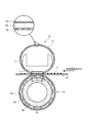
以下、図面を参照して本発明の実施形態を詳細に説明する。まず、本発明にかかる定着装置について図1を用いて説明する。図1は、本発明に係る定着装置の構成を示す概略断面図である。 Hereinafter, embodiments of the present invention will be described in detail with reference to the drawings. First, a fixing device according to the present invention will be described with reference to FIG. FIG. 1 is a schematic cross-sectional view showing a configuration of a fixing device according to the present invention.
[定着装置]
図1に示す定着装置10は、加熱体としてのヒータ1と、加熱体支持部材としてのヒータホルダ2と、定着部材としての定着ベルト3と、ニップ部形成部材としての加圧ローラ4とを備える。ヒータ1は、不図示の手段によって通電されることで発熱しかつ所定の制御温度に制御される例えば抵抗発熱体などの熱源である。ヒータ1は、剛性を有する耐熱性材料によって横断面略半円弧状の樋型に形成されるヒータホルダ2(以下、単にホルダと記す)に固定支持される。具体的には、ホルダ2の下面に長手方向(図1の紙面表裏方向)に沿って溝部が設けられており、この溝部にヒータ1が嵌入されている。
[Fixing device]
A
定着ベルト3は、内側から環状の基材3a、ベルト弾性層3b(ここでは、後述の加圧ローラ4の弾性層と区別するためにベルト弾性層と呼ぶ)、表層3cを備える。定着ベルト3は使用状態で内周面がヒータ1及びホルダ2に摺擦される無端ベルトであり、ヒータ1を支持したホルダ2の外周に周長に余裕を持たせて外嵌されている。定着ベルト3は、後述する加圧ローラ4の回転により従動回転する。このため定着ベルト3の長手方向両端部は、定着装置10のフレームなどの不図示の固定部分に回転自在に支持されている。定着ベルト3の内周面には、ヒータ1及びホルダ2との摺動性を確保するために潤滑剤(グリス)が塗られている。なお、本明細書でベルトと言った場合、フィルム状のものも含む。
The
加圧ローラ4は、内側から円筒状の基体4a、弾性層(4b,4c)、離型層4dを備える。加圧ローラ4は、例えばモータなどの回転駆動装置(不図示)によって使用時に回転駆動される。このため基体4aの軸方向両端部は、定着装置10のフレームなどの不図示の固定部分に回転自在に支持されている。また、加圧ローラ4は、ホルダ2に支持されたヒータ1と定着ベルト3を挟んで対向する位置に配置されている。そして、加圧機構(不図示)によって加圧ローラ4と定着ベルト3とに所定の圧力が付与されることで、加圧ローラ4と定着ベルト3とが圧接してそれぞれの弾性層(3b,4b,4c)は弾性変形する。これによって、加圧ローラ4と定着ベルト3との間には記録材搬送方向に所定の幅を有する定着ニップ部Nが形成される。
The
加圧ローラ4は回転駆動装置(不図示)によって回転駆動されると、従動回転する定着ベルト3との間で定着ニップ部Nにおいて記録材Pを挟持しつつ搬送する。また、定着ベルト3は、ヒータ1により表面が所定温度(例えば200℃)に達するまで加熱される。この状態で、未定着トナーTによって未定着トナー像の形成された記録材Pが定着ニップ部Nに挟持搬送されると、記録材P上の未定着トナーTは加熱、加圧される。すると、未定着トナーTは溶融/混色するので、その後、これを冷却することによって未定着トナー像を定着画像として記録材Pに定着させる。
When the
[定着ベルト]
定着ベルト3について説明する。定着ベルト3は、図1に示すように、基材3aの外周にベルト弾性層3bが、該ベルト弾性層3bの外周に表層3cが設けられている。基材3aは耐熱性及び耐屈曲性を必要とすることに鑑みて、例えばポリイミド、ポリアミドイミド、ポリエーテルエーテルケトン(PEEK)等の耐熱性樹脂を用いる。また熱伝導性をも考慮するならば、基材3aは耐熱性樹脂に比べ熱伝導率のより高いステンレス(SUS)、ニッケル、ニッケル合金などの金属を用いてもよい。そして、基材3aは熱容量を小さくする一方で機械的強度を高くする必要があるので、基材3aの厚みは5μm〜100μm好ましくは20μm〜85μmとするのが望ましい。
[Fixing belt]
The
ベルト弾性層3bは、基材3aの外周を被覆するシリコーンゴム層である。ベルト弾性層3bは記録材Pが定着ニップ部Nを通過する際に、記録材P上の未定着トナーTを包み込むようにして未定着トナーTに対し均一に熱を与える。ベルト弾性層3bがこのように機能することで、高光沢で定着ムラのない良質な画像が得られる。しかし、ベルト弾性層3bはその厚みが薄すぎると十分な弾性が得られなくなり、良質な画像を得ることができなくなる。反対に、ベルト弾性層3bはその厚みが厚すぎると熱容量が大きくなり、加熱によって所定温度に達するまでに時間がかかる。そのため、ベルト弾性層3bの厚みは、30μm〜500μm好ましくは100μm〜300μmとするのが望ましい。
The belt
ベルト弾性層3bは特に限定されないが、加工が容易である、高い寸法精度で加工できる、加熱硬化時に反応副生成物が発生しないなどの理由から、付加反応架橋型の液状シリコーンゴムを用いるのが好ましい。付加反応架橋型の液状シリコーンゴムは、例えばオルガノポリシロキサンとオルガノハイドロジェンポリシロキサンとを含み、さらには触媒や他の添加物を含んでいてもよい。オルガノポリシロキサンはシリコーンゴムを原料とするベースポリマーであり、数平均分子量が5千〜10万、重量平均分子量が1万〜50万であるものを用いるとよい。液状シリコーンゴムは室温で流動性を持つポリマーであるが加熱によって硬化し、硬化後は適度に低硬度でありまた十分な耐熱性と変形回復力を有する。そのため、液状シリコーンゴムはベルト弾性層3bだけでなく、後述する加圧ローラ4の非多孔質弾性層4bや多孔質弾性層4cに用いるのにも好適である。
Although the belt
ところで、ベルト弾性層3bがシリコーンゴム単体で形成されるならば、ベルト弾性層3bの熱伝導率は低くなる。ベルト弾性層3bの熱伝導率が低いとヒータ1で発生した熱が定着ベルト3を介して記録材Pに伝わり難くなるので、記録材Pにトナーを定着させる際に加熱不足となって定着ムラなどの画像不良を生じ得る。そこで、ベルト弾性層3bの熱伝導率を上げるために、ベルト弾性層3bには高い熱伝導性を持つ例えば粒状の高熱伝導性フィラーが混入、分散されている。粒状の高熱伝導性フィラーとしては、炭化ケイ素(SiC)、酸化亜鉛(ZnO)、アルミナ(Al2O3)、窒化アルミニウム(AlN)、酸化マグネシウム(MgO)、カーボン等が用いられる。また、目的に応じて粒状の高熱伝導性フィラーではなく針状の高熱伝導性フィラーなどを用いてもよい。すなわち、高熱伝導性フィラーの形状は粒状や針状の他にも、粉砕状、板状、ウィスカ状のものなどがあり、ベルト弾性層3bにはこれらのどの形状のものを用いてもよい。また、これらのものを単独で用いてもよいし2種類以上のものを混合して用いてもよい。なお、高熱伝導性フィラーがベルト弾性層3bに混入されることで、ベルト弾性層3bは導電性をも付与され得る。
By the way, if the belt
表層3cは、ベルト弾性層3bの外周を被覆するフッ素樹脂層である。表層3cは、定着ベルト3にトナーを付着しにくくするために設けられる。表層3cには、四フッ化エチレン・パーフロロアルキルビニルエーテル共重合体樹脂(PFA)、四フッ化エチレン樹脂(PTFE)、四フッ化エチレン・六フッ化プロピレン共重合体樹脂(FEP)等のフッ素樹脂を用いるとよい。表層3cの厚みは、1μm〜50μm好ましくは8μm〜25μmとするのが望ましい。なお、表層3cはフッ素樹脂チューブで被覆するもしくはフッ素樹脂からなる塗料を塗布することによって、ベルト弾性層3bの外周に形成されればよい。
The
[加圧ローラ]
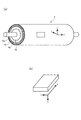
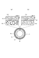
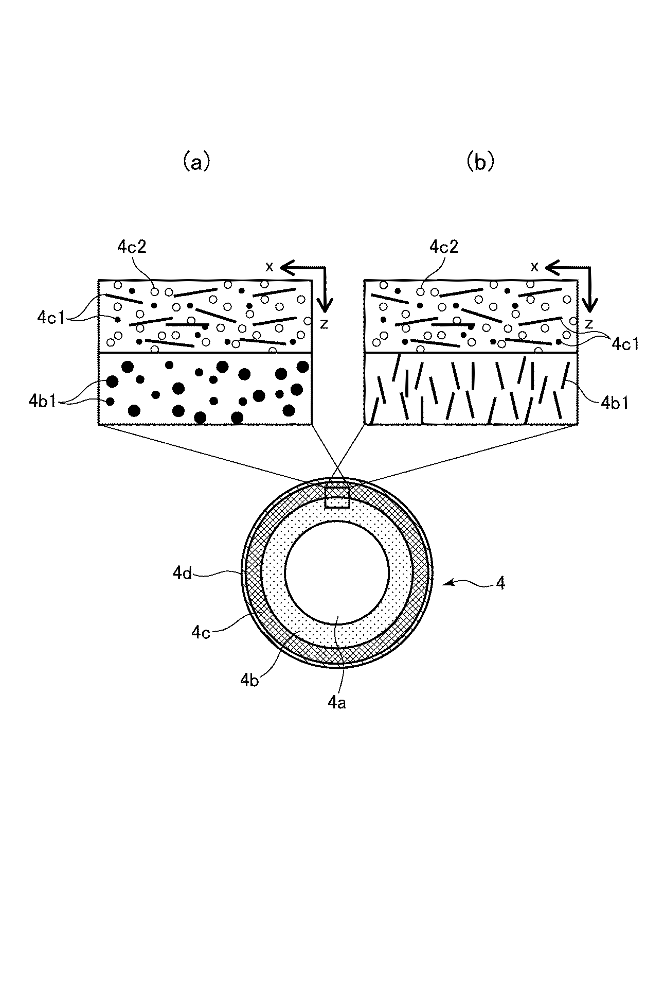
加圧ローラ4について説明する。加圧ローラ4は、基体4a、基体4aの外周に弾性層(4b,4c)、該弾性層(4b,4c)の外周に離型層4dを備える。本発明に係る加圧ローラ4は、基体4a側に第一弾性層としての非多孔質弾性層4bを、離型層4d側に第二弾性層としての多孔質弾性層4cを配して、弾性層を特性の異なる層で構成した点に特徴がある。図2は、加圧ローラ4の全体構成を示す斜視図である。図3は、非多孔質弾性層4b及び多孔質弾性層4cのxz断面を示す拡大図である。なお、図2(a)に示すように、以下では加圧ローラ4の周方向を「x」方向、加圧ローラ4の長手方向(軸方向)を「y」方向、加圧ローラ4の厚み方向(層厚方向)を「z」方向と表す。
[Pressure roller]
The
<基体>
基体4aは、ニッケルやクロムをメッキしたSUM材(硫黄および硫黄複合快削鋼鋼材)等の鋼材を含むステンレススチール、リン青銅、アルミニウムなどを用いて形成されている軸芯体あるいは芯金である。基体4aの外径は、4mm〜80mmであればよい。
<Substrate>
The
<非多孔質弾性層>
非多孔質弾性層4bは、基体4aの外周を被覆するシリコーンゴム層である。図3に示すように、非多孔質弾性層4bには、粒状あるいは針状の高熱伝導性フィラー4b1が混入、分散されている。図3(a)は粒状の高熱伝導性フィラー4b1が混入されている場合を示し、図3(b)は針状の高熱伝導性フィラー4b1が混入されている場合を示している。
<Non-porous elastic layer>
The non-porous
粒状あるいは針状の高熱伝導性フィラー4b1について説明する。粒状の高熱伝導性フィラー4b1としては、定着ベルト3のベルト弾性層3bと同様に、炭化ケイ素(SiC)、酸化亜鉛(ZnO)、アルミナ(Al2O3)、窒化アルミニウム(AlN)、酸化マグネシウム(MgO)、カーボン等が用いられる。非多孔質弾性層4bに粒状の高熱伝導性フィラー4b1を混入することで、本実施例では特に非多孔質弾性層4bの厚み方向(z方向)の熱伝導率が多孔質弾性層4cの厚み方向の熱伝導率に比して高くなるようにしている。具体的には、非多孔質弾性層4bの厚み方向(z方向)の熱伝導率が「0.50W/(m・k)」以上となるように、非多孔質弾性層4b内に粒状の高熱伝導性フィラー4b1が混入、分散される。
The granular or acicular high thermal conductive filler 4b1 will be described. As the granular high thermal conductive filler 4b1, like the belt
針状の高熱伝導性フィラー4b1(以下、単に針状フィラー4b1と記す)としては、フィラー長手方向の熱伝導率が500W/(m・K)以上のピッチ系炭素繊維が用いられる。ピッチ系炭素繊維は石油精製副産物あるいは石炭乾留副産物である「ピッチ」から製造された炭素繊維であり、高い熱伝導性や導電性を有する一方で熱膨張がほとんど無い、といった特徴を持つ。針状フィラー4b1は例えば円柱や多角柱などの形状をした細長い棒状をした、直径に対する長さの比が大きいつまりアスペクト比が高い部材である。そして、針状フィラー4b1は配向された向きに熱を伝えやすい熱伝導異方性を有している。本実施例では、図3(b)に示すように、針状フィラー4b1を非多孔質弾性層4bの厚み方向(z方向)に配向した状態に混入している。こうすることにより、上述したように、非多孔質弾性層4bの厚み方向(z方向)の熱伝導率が多孔質弾性層4cの厚み方向の熱伝導率に比して高くなるようにしている。
As the acicular high thermal conductive filler 4b1 (hereinafter simply referred to as the acicular filler 4b1), pitch-based carbon fibers having a thermal conductivity in the filler longitudinal direction of 500 W / (m · K) or more are used. Pitch-based carbon fiber is a carbon fiber manufactured from “pitch”, which is a by-product of petroleum refining or a coal-distillation by-product, and has a feature that it has high thermal conductivity and conductivity, but has almost no thermal expansion. The needle-like filler 4b1 is a member having a long rod-like shape such as a cylinder or a polygonal column and having a large ratio of length to diameter, that is, a high aspect ratio. The needle-like filler 4b1 has thermal conductivity anisotropy that easily transfers heat in the oriented direction. In this embodiment, as shown in FIG. 3B, the needle-like filler 4b1 is mixed in a state oriented in the thickness direction (z direction) of the non-porous
非多孔質弾性層4bの針状フィラー4b1に用いるピッチ系炭素繊維は、平均直径が5μm〜11μm程度かつ平均長さが50μm〜1000μm程度のものが好ましい。なぜなら平均長さが50μmよりも短いと、非多孔質弾性層4bの熱伝導率に異方性効果が現れ難くなるからである。一方、平均長さが1000μmよりも長いと、非多孔質弾性層4b内に分散させることが難しくなるからである。
The pitch-based carbon fiber used for the needle-like filler 4b1 of the nonporous
非多孔質弾性層4b内における粒状あるいは針状の高熱伝導性フィラー4b1の分散含有量は、体積比5%〜60%であるのが望ましい。なぜなら、これらの高熱伝導性フィラー4b1の分散含有量が体積比5%未満の場合には、熱伝導率を高めることができず、非通紙部昇温の発生抑制に十分な熱伝導率が得られないからである。他方、高熱伝導性フィラー4b1の分散含有量が体積比60%を上回る場合には、液状シリコーンゴムの流動性が低下して弾性層の加工成型が難しくなるからである。また、後述するようにして硬化した後に、ゴムの硬度が上がりつまりゴムが硬くなってしまい弾性層としての機能が失われ得るからである。なお、高熱伝導性フィラー4b1としては上述した粒状や針状などの単一形状のものだけを用いてもよいし、これらを含む2種類以上の異なる形状のものを複数混合して用いてもよい。
The dispersion content of the granular or needle-like highly thermally conductive filler 4b1 in the non-porous
<多孔質弾性層>
多孔質弾性層4cは、非多孔質弾性層4bの外周を被覆するシリコーンゴム層である。図3(a)及び(b)に示すように、多孔質弾性層4cには、針状の高熱伝導性フィラー4c1(以下、単に針状フィラー4c1と記す)が長手方向(図3の紙面表裏方向)及び周方向(図3の左右方向)に配向された状態に混入、分散されている。この針状フィラー4c1にも、上述したピッチ系炭素繊維を用いる。針状フィラー4c1が混入されることで、多孔質弾性層4cにも熱伝導異方性の効果が現れる。本実施例では、厚み方向の熱伝導率よりも面方向(xy面)の熱伝導率が高くなるように多孔質弾性層4cを形成する。特には、長手方向の熱伝導率及び周方向の熱伝導率を高くしている。より具体的には、長手方向の熱伝導率及び周方向の熱伝導率は厚み方向の熱伝導率よりも6倍〜20倍ほど高い(後述の表1参照)。
<Porous elastic layer>
The porous
多孔質弾性層4cにはさらに、非多孔質弾性層4bに存在しない空孔部4c2が多数形成されている。空孔部4c2を形成することによって、多孔質弾性層4cの低熱容量化が図られている。また、空孔部4c2が形成されると、多孔質弾性層4cの厚み方向の熱伝導率は非多孔質弾性層4bの厚み方向の熱伝導率よりも低くなる。つまりは、空孔部4c2の形成によっても、非多孔質弾性層4bの厚み方向の熱伝導率が多孔質弾性層4cの厚み方向の熱伝導率に比して高くなるようにしている。
The porous
多孔質弾性層4c及び非多孔質弾性層4bは、略均一な厚みで形成される。多孔質弾性層4cの厚みは0.3mm〜5.0mm程度好ましくは0.5mm以上であればよい。これに対し、非多孔質弾性層4bの厚みは特に限定されるものではなく、多孔質弾性層4cの厚みや硬度に応じて調整されればよい。すなわち、非多孔質弾性層4bの厚みは、多孔質弾性層4cを含む弾性層全体が定着ベルト3に圧接し弾性変形したときに、所望の幅の定着ニップ部Nを形成し得る厚みであればよい。ただし、非多孔質弾性層4bと多孔質弾性層4cとを含む弾性層全体の厚みは、2.0mm〜10.0mm程度とするのが好ましい。なお、多孔質弾性層4cの硬度は、所望の幅の定着ニップ部Nを確保する観点から20°〜70°の範囲内であるのが好ましい。
The porous
<離型層>
離型層4dは、フッ素樹脂層である。離型層4dは、多孔質弾性層4cの外周に例えば共重合体(PFA)チューブを被覆することにより形成される。もしくはPFA、ポリテトラフルオロエチレン(PTFE)、テトラフルオロエチレン‐ヘキサフルオロプロピレン共重合体(FEP)等のフッ素樹脂からなる塗料を多孔質弾性層4c外周に塗布することにより形成してもよい。離型層4dの厚みは特に限定されないが、好ましくは15〜80μm程度であればよい。この離型層4dは、加圧ローラ4にトナーを付着しにくくするために設けられる。
<Release layer>
The
なお、非多孔質弾性層4bと多孔質弾性層4cの間や、多孔質弾性層4cと離型層4dの間には接着、通電等の目的によりプライマー層や接着層などが設けられていてもよい。
A primer layer or an adhesive layer is provided between the non-porous
[非多孔質弾性層の形成方法]
次に、非多孔質弾性層4b、多孔質弾性層4c、離型層4dの形成方法について説明する。まず、非多孔質弾性層4bの形成方法について説明する。非多孔質弾性層4bの形成方法は特に限定されないが、一般的な型成型による方法もしくはリング塗工法を好適に用いることができる。ここでは、リング塗工法を例に説明する。
[Method of forming non-porous elastic layer]
Next, a method for forming the non-porous
基体4aには予めプライマー処理が施される。プライマー処理が施された基体4aは、軸が垂直に立てられた状態で保持体により保持される。保持体に保持された基体4aの周囲を囲むようにしてリング状の塗工ヘッドが配置されており、該リング状塗工ヘッドの内面には吐出口が設けられている。弾性層を形成する場合、基体4aを上下に移動させながら、リング状塗工ヘッドの吐出口から後述の液状ゴム混合物を基体4aの外周面に向けて吐出する。こうして、基体4aの外周面に液状ゴム混合物の塗膜を形成する。その後、基体4aを垂直保持状態から水平保持状態へと移行してから例えば回転数60rpmで回転する。回転する基体4aを近赤外線ヒータ等により加熱し、基体4aの表面温度を約180℃にする。この状態を3分間維持することで、液状シリコーンゴムを加熱硬化させる。その後、さらに200℃の熱風循環式オーブンを用いて基体4aを加熱することで、液状シリコーンゴムを2次硬化させる。このようにして、非多孔質弾性層4bは基体4aの外周に形成される。
The
非多孔質弾性層4bには、液状シリコーンゴムに粒状又は針状の高熱伝導性フィラー4b1を混合した液状ゴム混合物が用いられる。針状フィラー4b1を混合した液状ゴム混合物を用いる場合、リング状塗工ヘッドの吐出口から液状シリコーンゴムとともに吐出された針状フィラー4b1は、液状シリコーンゴムの流れに沿う向きに自然に揃えられる。そこで、熱をより多く伝導させたい向きに液状シリコーンゴムが流れるようにすれば、針状フィラー4b1をその向きに配向することができる。こうして、針状フィラー4b1が任意の向きに配向されることにより、非多孔質弾性層4bの任意の方向の熱伝導率をそれ以外の方向の熱伝導率よりも高くすることができる。本実施例では、液状シリコーンゴムの流れの向きを厚み方向(z方向)に向けることで、非多孔質弾性層4bの厚み方向の熱伝導率を高くする。こうすると、非多孔質弾性層4bから基体4aへと熱が伝わりやすくなる。
For the non-porous
[多孔質弾性層の形成方法]
多孔質弾性層4cの形成方法及び離型層4dの形成方法について説明する。
[Method of forming porous elastic layer]
A method for forming the porous
(1)液状ゴム混合物の生成
針状フィラー4c1と吸水性ポリマーに水分を含ませた含水材料とを、液状シリコーンゴムに混合して液状ゴム混合物を生成する。この液状ゴム混合物を生成するには、液状シリコーンゴムと針状フィラー4c1と含水材料の各々を所定量ずつ秤量して、これらを遊星式の万能混合攪拌機など公知のフィラー混合撹拌手段を用いて攪拌すればよい。
(1) Formation of liquid rubber mixture The needle-shaped filler 4c1 and a water-containing material obtained by adding water to a water-absorbing polymer are mixed with liquid silicone rubber to form a liquid rubber mixture. In order to produce this liquid rubber mixture, a predetermined amount of each of the liquid silicone rubber, the needle-like filler 4c1, and the water-containing material is weighed and stirred using a known filler mixing and stirring means such as a planetary universal mixing stirrer. do it.
(2)液状ゴム混合物を用いた多孔質弾性層4cの形成
多孔質弾性層4cの形成方法は特に限定されないが、ここでは一般的な型成型を例に説明する。多孔質弾性層4cを形成する前に、非多孔質弾性層4bに予めプライマー処理が施される。その後、この基体4aは金型内に配置される。そして、配置された基体4aの軸方向に沿うようにして、金型内に液状ゴム混合物が流し込まれる(注型する)。基体4aの軸方向に沿うように金型内に液状ゴム混合物が流し込まれると、針状フィラー4c1の多くは液状ゴム混合物の流れに従って、基体4aの軸方向つまり加圧ローラ4の長手方向(y方向)に配向される。したがって、多孔質弾性層4cの長手方向の熱伝導率はそれ以外の方向の熱伝導率よりも高くなる。長手方向の熱伝導率がそれ以外の方向の熱伝導率よりも高いと、非通紙部の温度が高くなり始めたときに、非通紙部から相対的に温度の低い通紙部や加圧ローラ両端部側へと非通紙部の熱が伝わりやすくなる。つまり、非通紙部の熱を効率的に拡散することができるようになる。
(2) Formation of
なお、液状ゴム混合物が基体4aの軸方向に沿うように金型内に流し込まれたとしても、液状ゴム混合物の流れが金型内で乱れることがある。その場合、液状ゴム混合物は記録材Pの搬送方向つまり周方向(x方向)や周方向に交差する方向(y方向を含んでよい)にも流れる。そのため、多孔質弾性層4cにおいて、針状フィラー4c1は主に長手方向に配向されるがこれだけに限られず、長手方向及び周方向を含む面方向(xy面)に配向されるものもある。その場合、長手方向の熱伝導率だけでなく周方向の熱伝導率も高くなるが、周方向の熱伝導率が高くなっても非通紙部昇温の抑制に効果的であるので何ら問題ない。すなわち、多孔質弾性層4cにおいて針状フィラー4c1の向きは面方向(xy面)であれば、いずれの向きであっても非通紙部昇温の抑制には効果的である。
Even if the liquid rubber mixture is poured into the mold along the axial direction of the
(3)シリコーンゴム成分の架橋硬化
金型を液状ゴム混合物で充填した後、金型を密閉して加熱する。液状ゴム混合物は金型ごと、水の沸点以下の温度例えば60℃〜90℃で5分〜120分間加熱処理される。密閉下で液状ゴム混合物が加熱処理されると、シリコーンゴム成分は含水材料中の水分を保持したまま架橋硬化する。
(3) Crosslinking curing of silicone rubber component After the mold is filled with the liquid rubber mixture, the mold is sealed and heated. The liquid rubber mixture is heat treated together with the mold at a temperature below the boiling point of water, for example, 60 ° C. to 90 ° C. for 5 minutes to 120 minutes. When the liquid rubber mixture is heat-treated under hermetic conditions, the silicone rubber component is crosslinked and cured while retaining moisture in the water-containing material.
(4)加圧ローラの脱型
加熱した金型を水冷方式や空冷方式によって冷却した後に、金型から加圧ローラ4を脱型する。脱型された加圧ローラ4は、非多孔質弾性層4bの外周に多孔質弾性層4cが積層されている。
(4) Demolding of pressure roller After the heated mold is cooled by a water cooling method or an air cooling method, the
(5)空孔部の形成
脱型した加圧ローラ4を加熱する。加熱によって多孔質弾性層4c内の温度が上昇するに従って含水材料に含まれていた水分が蒸発するので、当該箇所に空孔部4c2が形成される。このときの加圧ローラ4を加熱する際の条件として、加熱温度は100℃〜250℃に、加熱時間は1〜5時間に設定するのが望ましい。以上のようにして、針状フィラー4c1及び空孔部4c2を有する多孔質弾性層4cが非多孔質弾性層4bの外周に形成される。
(5) Formation of hole part The depressurized
(6)離型層の形成
離型層4dは、多孔質弾性層4cにフッ素樹脂製チューブを被覆することにより形成される。フッ素樹脂製チューブを被覆するには、一般的に接着剤を用いる。ただし、接着剤を用いずとも多孔質弾性層4cとフッ素樹脂製チューブとを層間接着できる場合があり、そうした場合には接着剤を用いなくてもよい。また、離型層4dは、多孔質弾性層4c外周にフッ素樹脂からなる塗料を塗布するなどして形成してもよい。あるいは、離型層4dは多孔質弾性層4cと共に形成してもよい。すなわち、予めフッ素樹脂チューブを内面に配置した金型内に、非多孔質弾性層4bを形成済みの基体4aを配置する。そして、この非多孔質弾性層4bとフッ素樹脂チューブとの間に液状ゴム混合物を流し込むことによって、離型層4dが形成された状態で多孔質弾性層4cを形成するようにしてもよい。なお、金型内に配置するフッ素樹脂チューブは内面がエッチング処理され、かつ内面に予めプライマーを塗布乾燥させたものを用いる。
(6) Formation of Release Layer The
[加圧ローラの評価]
以下、本発明に係る加圧ローラ4の評価について、後述する実施例1乃至4、比較例1乃至3を用いて説明する。本実施例では、評価のためにそれぞれの熱伝導率を求めている。
[Evaluation of pressure roller]
Hereinafter, evaluation of the
<熱伝導率>
熱伝導率は、熱拡散率から換算する。熱拡散率の計測には、温度可変型の温度波熱分析法によって熱拡散率を測定するタイプの装置を用いた。このタイプの装置として、例えば「ai−Phase Mobile2」(商品名、株式会社アイフェイズ製)の熱拡散率測定装置が挙げられる。この装置を用いて、図2(a)に示すような加圧ローラ4の周方向(x方向)及び加圧ローラ4の長手方向(y方向)及び加圧ローラ4の厚み方向(z方向)について、それぞれの熱拡散率を測定した。図2(b)に示すように、周方向(x方向)の熱拡散率測定には、yz面に切り込みを入れてx方向の厚みが1mm以下になるように切り出したものを被測定試料とした。長手方向(y方向)の熱拡散率測定には、zx面に切り込みを入れてy方向の厚みが1mm以下となるように切り出したものを被測定試料とした。厚み方向(z方向)の熱拡散率測定には、xy面に切り込みを入れてz方向の厚みが1mm以下となるように切り出したものを被測定試料とした。そして、これらの被測定試料を用いて温度設定50℃にて各方向毎に熱拡散率測定を5回ずつ行い、5回の平均値をそれぞれ周方向熱拡散率、長手方向熱拡散率、厚み方向熱拡散率とした。
<Thermal conductivity>
Thermal conductivity is converted from thermal diffusivity. For the measurement of the thermal diffusivity, a device of a type that measures the thermal diffusivity by a temperature variable thermal wave thermal analysis method was used. As this type of apparatus, for example, a thermal diffusivity measuring apparatus of “ai-
熱拡散率から熱伝導率を換算するには、密度と比熱容量の各値が必要である。密度の計測には、例えば「Accupyc 1330」(商品名、株式会社島津製作所製)といった乾式自動密度計を用いる。また、比熱容量の計測には、例えば「DSC823」(商品名、メトラー・トレド株式会社製)といった示差走査型熱量測定装置を用いる。このときに比熱容量を比較するために基準とする、比熱容量が既知の物質にはサファイアを用いた。この測定装置による比熱容量測定を5回行って、5回の平均値を比熱容量とした。熱伝導率は、こうして得られた密度と比熱容量とを乗算し、さらにその結果に上述の熱拡散率を乗算して求めた。 In order to convert thermal conductivity from thermal diffusivity, each value of density and specific heat capacity is required. For the measurement of the density, for example, a dry automatic densimeter such as “Acupyc 1330” (trade name, manufactured by Shimadzu Corporation) is used. For the measurement of specific heat capacity, for example, a differential scanning calorimeter such as “DSC823” (trade name, manufactured by METTLER TOLEDO Co., Ltd.) is used. At this time, sapphire was used as a material having a known specific heat capacity as a reference for comparing the specific heat capacities. Specific heat capacity measurement with this measuring apparatus was performed 5 times, and the average value of 5 times was defined as the specific heat capacity. The thermal conductivity was obtained by multiplying the density thus obtained and the specific heat capacity, and further multiplying the result by the above-mentioned thermal diffusivity.
<性能評価>
性能評価は、図1に示した定着装置に実施例1乃至4の加圧ローラ、比較例1乃至3の加圧ローラをそれぞれ組み込んでなるレーザープリンタを用いて行った。このレーザープリンタにおける加圧ローラの回転速度(周速)は246mm/secとした。
<Performance evaluation>
The performance evaluation was performed using a laser printer in which the pressure roller of Examples 1 to 4 and the pressure roller of Comparative Examples 1 to 3 were incorporated in the fixing device shown in FIG. The rotation speed (circumferential speed) of the pressure roller in this laser printer was 246 mm / sec.
(非通紙部昇温の評価)
非通紙部昇温の評価は、低温度(15℃程度)かつ低湿度(10%程度)の環境下で、A4横サイズ紙(商品名「CS−680」、キヤノン株式会社製)を50枚/分で10分間連続プリントした後に測定した定着ベルト3の非通紙部の表面温度に基づき行った。具体的には、定着ニップ部N(図1参照)から記録材搬送方向上流側90°に位置する定着ベルト3の表面温度が170℃を維持するように、ヒータ1による加熱温度を調整しながら500枚連続プリントを行う。そして、500枚連続プリントが終了してから、定着ベルト3の非通紙部領域(A4横サイズ紙が通過しない領域)の表面温度を放射型温度計で測定した。ここでは、未定着トナー像を定着画像として記録材に定着する際に、定着ベルト3が所定温度(例えば200℃)にまで加熱されることに鑑み、非通紙部領域の表面温度が250℃よりも低ければ非通紙部昇温の発生を抑制できているとした。
(Evaluation of temperature rise in non-sheet passing area)
The evaluation of the temperature rise of the non-sheet passing portion was 50 for A4 landscape paper (trade name “CS-680”, manufactured by Canon Inc.) under a low temperature (about 15 ° C.) and low humidity (about 10%) environment. The measurement was performed based on the surface temperature of the non-sheet passing portion of the fixing
(立ち上がり時間の評価)
立ち上がり時間の評価も非通紙部昇温の評価と同様に、低温低湿環境下(15℃/10%)で行った。立ち上がり時間は、定着ベルト3が通紙を行っていない空回転状態にあるときに、ヒータ1による加熱開始から定着ベルト3の表面温度が170℃に達するまでにかかる時間を測定した。ここでは、立ち上がり時間が10.8秒よりも短ければ、立ち上がり時間が短縮できているとした。
(Evaluation of rise time)
The rise time was also evaluated in a low-temperature and low-humidity environment (15 ° C./10%), similarly to the evaluation of the temperature increase in the non-sheet passing portion. As the rise time, the time required from the start of heating by the heater 1 to the surface temperature of the fixing
<評価結果>
後述する実施例1乃至4の加圧ローラ、及び比較例1乃至3の加圧ローラについて、非通紙部領域の表面温度(非通紙部温度)及び定着部材の立ち上がり時間の評価結果を熱伝導率の測定結果とともに表1に示す。表1に示すように、多孔質弾性層4cの長手方向の熱伝導率(λy)及び周方向の熱伝導率(λx)は、厚み方向の熱伝導率(λz)よりも6倍以上である。
<Evaluation results>
For the pressure rollers of Examples 1 to 4 and the pressure rollers of Comparative Examples 1 to 3 to be described later, the evaluation results of the surface temperature of the non-sheet passing portion region (non-sheet passing portion temperature) and the rise time of the fixing member are heated. It shows in Table 1 with the measurement result of conductivity. As shown in Table 1, the thermal conductivity (λy) in the longitudinal direction and the thermal conductivity (λx) in the circumferential direction of the porous
実施例1乃至4の加圧ローラ、及び比較例1乃至3の加圧ローラはすべて共通に、基体4aは外径φ24mmの鉄製の芯金を用いた。芯金の周面に塗布するプライマーは、「DY39−051」(商品名、東レ・ダウコーニング株式会社製)を用いた。また、加圧ローラの外径をφ30mmとし、さらには非多孔質弾性層4bの厚みと多孔質弾性層4cの厚みとを加算した合計値つまりは弾性層全体の厚みを3.0mmとした。
The pressure rollers of Examples 1 to 4 and the pressure rollers of Comparative Examples 1 to 3 were all common, and the
(実施例1の加圧ローラ)
非多孔質弾性層4b用の液状ゴム混合物は、付加反応架橋型の液状シリコーンゴムに高熱伝導性フィラー4b1として粒状アルミナ(商品名「アルナビーズCB−A20S」、昭和電工株式会社製)を体積比50%の割合で混合したものを使用した。一方、多孔質弾性層4c用の液状ゴム混合物は、含水材料としてポリアクリル酸ナトリウム(商品名「レオジック250H」、日本純薬株式会社製)を体積比50%の割合で混合したものを使用した。また、水を含ませたときの含水材料中のポリアクリル酸ナトリウムの割合を1重量%とした。さらに、多孔質弾性層4c用の液状ゴム混合物には、針状フィラー4c1を体積比10%の割合で混合してある。実施例1では、針状フィラー4c1として平均繊維長が250μmのピッチ系炭素繊維(商品名「GRANOCミルドファイバー(XN−100−25M)」、日本グラファイトファイバー株式会社製)を用いた。このピッチ系炭素繊維は、平均繊維径が9μm、フィラー長手方向の熱伝導率が900W/(m・k)である(以下、同じ)。そして、実施例1では多孔質弾性層4cの厚みを2.0mmとした。なお、多孔質弾性層4cの厚みを2.0mmかつ弾性層全体の厚みを3.0mmとしたので、非多孔質弾性層4bの厚みは1.0mmに決まる。実施例1の加圧ローラ4の非多孔質弾性層4b及び多孔質弾性層4cは、図3(a)に示すような構成である。
(Pressure roller of Example 1)
The liquid rubber mixture for the non-porous
(実施例2の加圧ローラ)
非多孔質弾性層4b用の液状ゴム混合物は、実施例1と同じものを使用した。一方、多孔質弾性層4c用の液状ゴム混合物には、針状フィラー4c1を体積比20%の割合で混合したものを使用した。実施例2では、針状フィラー4c1として平均繊維長が100μmのピッチ系炭素繊維(商品名「GRANOCミルドファイバー(XN−100−10M)」、日本グラファイトファイバー株式会社製)を用いた。含水材料は実施例1と同様のものを使用した。そして、実施例2では非多孔質弾性層4bの厚みを1.5mm、多孔質弾性層4cの厚みを1.5mmとした。実施例2の加圧ローラ4の非多孔質弾性層4b及び多孔質弾性層4cは、図3(a)に示すような構成である。
(Pressure roller of Example 2)
The same liquid rubber mixture as used in Example 1 was used for the non-porous
(実施例3の加圧ローラ)
非多孔質弾性層4b用の液状ゴム混合物には、付加反応架橋型の液状シリコーンゴムに高熱伝導性フィラー4b1として針状フィラーを体積比25%の割合で混合したものを使用した。針状フィラー4b1として、上述の平均繊維長が100μmのピッチ系炭素繊維(XN−100−10M)を用いた。一方、多孔質弾性層4c用の液状ゴム混合物には、針状フィラー4c1を体積比15%の割合で混合したものを使用した。実施例3では、針状フィラー4c1として平均繊維長が200μmのピッチ系炭素繊維(商品名「GRANOCミルドファイバー(XN−100−20M)」、日本グラファイトファイバー株式会社製)を用いた。含水材料は実施例1と同様のものを使用した。そして、実施例3では非多孔質弾性層4bの厚み及び多孔質弾性層4cの厚みを実施例1と同様に1.0mmと2.0mmとした。実施例3の加圧ローラ4の非多孔質弾性層4b及び多孔質弾性層4cは、図3(b)に示すような構成である。
(Pressure roller of Example 3)
As the liquid rubber mixture for the non-porous
(実施例4の加圧ローラ)
非多孔質弾性層4b用の液状ゴム混合物は、実施例1と同じものを使用した。一方、多孔質弾性層4c用の液状ゴム混合物は、針状フィラー4c1としてピッチ系炭素繊維(上記のXN−100−10M)を体積比10%の割合で混合しかつ含水材料の割合を体積比30%とした以外は、実施例1と同様のものを使用した。そして、実施例4では非多孔質弾性層4bの厚みを1.5mm、多孔質弾性層4cの厚みを1.5mmとした。実施例4の加圧ローラ4の非多孔質弾性層4b及び多孔質弾性層4cは、図3(a)に示すような構成である。
(Pressure roller of Example 4)
The same liquid rubber mixture as used in Example 1 was used for the non-porous
(比較例1〜3の加圧ローラ)
比較例1は、非多孔質弾性層4bに高熱伝導性フィラー4b1が混入されていない点が実施例1と異なる。比較例2は、多孔質弾性層4cに空孔部4c2が形成されていない点が実施例2と異なる(空隙割合が0)。比較例3は、多孔質弾性層4cに針状フィラー4c1が混入されていない点が実施例3と異なる。
(Pressure roller of Comparative Examples 1 to 3)
Comparative Example 1 is different from Example 1 in that the high thermal conductive filler 4b1 is not mixed in the non-porous
比較例1〜比較例3の結果をみると、比較例1〜比較例3の加圧ローラでは、非通紙部昇温の発生抑制と定着部材の立ち上がり時間の短縮のいずれか一方の効果しか得られないことが理解できる。すなわち、比較例1は非通紙部温度が250℃であり、非通紙部昇温の発生を抑制できていない。これは、非多孔質弾性層4bに高熱伝導性フィラー4b1が混入されていないために、非通紙部の熱が通紙部や加圧ローラ両端部さらには基体4aに伝わり難いからである。比較例2は非通紙部温度が230℃であり、非通紙部昇温の発生を抑制できている。しかし、立ち上がり時間が12.0秒であり、立ち上がり時間が長い。これは、多孔質弾性層4cに空孔部4c2が形成されていないがために多孔質弾性層4cの熱伝導率が大きく、定着部材が加熱されてもその熱が加圧ローラ4に伝わりやすいからである。比較例3は立ち上がり時間が9.2秒であり、立ち上がり時間は短い。しかし、非通紙部温度は260℃と高く、非通紙部昇温の発生を抑制できていない。これは、多孔質弾性層4cに針状フィラー4c1が混入されていないために、非通紙部の熱が通紙部や加圧ローラ両端部に伝わり難いからである。
The results of Comparative Examples 1 to 3 show that the pressure roller of Comparative Examples 1 to 3 has only one of the effects of suppressing the occurrence of non-sheet passing portion temperature rise and shortening the rise time of the fixing member. It can be understood that it cannot be obtained. That is, in Comparative Example 1, the non-sheet passing portion temperature is 250 ° C., and the occurrence of the non-sheet passing portion temperature rise cannot be suppressed. This is because the high heat conductive filler 4b1 is not mixed in the non-porous
これに対し、実施例1〜実施例4の結果をみると、実施例1〜実施例4の加圧ローラはすべて、非通紙部温度が250℃より低くかつ立ち上がり時間が10.8秒以下となっている。つまり、非通紙部昇温の発生抑制と定着部材の立ち上がり時間の短縮の両方の効果が得られている。定着部材の立ち上がり時間の短縮効果について説明する。実施例1〜実施例4の加圧ローラの場合、多孔質弾性層4c内に空孔部4c2を設けて多孔質弾性層4cの熱伝導率を低くしている。多孔質弾性層4cの熱伝導率が低いと定着部材から加圧ローラへと熱が伝わり難い。また、多孔質弾性層4cから非多孔質弾性層4bへと熱が伝わるのは、低熱容量の多孔質弾性層4cに蓄えられた熱量が熱容量を超えるような場合である。したがって、さほど多くの熱量が生じることのない定着部材の立ち上がりの際には、多孔質弾性層4cから非多孔質弾性層4bへと熱が伝わることもないので、定着部材の立ち上がり時間は短くなる。
On the other hand, looking at the results of Examples 1 to 4, all of the pressure rollers of Examples 1 to 4 have a non-sheet passing portion temperature lower than 250 ° C. and a rise time of 10.8 seconds or less. It has become. That is, the effects of both suppressing the occurrence of temperature rise at the non-sheet passing portion and shortening the rise time of the fixing member are obtained. The effect of shortening the rise time of the fixing member will be described. In the case of the pressure roller of Example 1 to Example 4, the hole 4c2 is provided in the porous
非通紙部昇温の発生抑制の効果について説明する。実施例1〜実施例4の加圧ローラでは、多孔質弾性層4c内の針状フィラー4c1によって非通紙部の熱が通紙部や加圧ローラ両端部へと逃れる。これに加えて、多孔質弾性層4cから非多孔質弾性層4bへと熱が伝わると、その熱は非多孔質弾性層4b内の高熱伝導性フィラー4b1によって基体4a(芯金)へと逃れる。すなわち、非通紙部の熱を非多孔質弾性層4bと多孔質弾性層4cに比べると相対的に熱伝導率の高い基体4a(芯金)を通じて逃すことができる。こうして、非通紙部昇温の発生を抑制することができる。なお、実施例3の非通紙部温度(210℃)が他の実施例と比べて特に低いのは、非多孔質弾性層4b内の高熱伝導性フィラー4b1として熱伝導異方性を有する針状フィラーを使用したことによる。
The effect of suppressing the occurrence of non-sheet passing portion temperature rise will be described. In the pressure roller of Examples 1 to 4, the heat of the non-sheet passing portion escapes to the sheet passing portion and both ends of the pressure roller by the needle-like filler 4c1 in the porous
以上のように、本発明に係る加圧ローラ4は、その弾性層が非多孔質弾性層4bと多孔質弾性層4cとからなる特性の異なる層で形成される。非多孔質弾性層4bの特性としては、厚み方向の熱伝導率(λz)が多孔質弾性層4cの厚み方向の熱伝導率(λz)よりも高い。他方、多孔質弾性層4cの特性としては、厚み方向の熱伝導率(λz)に比較して長手方向の熱伝導率(λy)及び周方向の熱伝導率(λx)が高い。また、厚み方向の熱伝導率(λz)が非多孔質弾性層4bの厚み方向の熱伝導率(λz)よりも低い。さらに、多孔質弾性層4cは低熱容量である。このような特性の異なる層を弾性層が含むが故に、非通紙領域での過度な温度上昇の発生を抑制することができかつ定着部材の立ち上がり時間を短くすることができる。
As described above, in the
なお、上述した実施例では、非多孔質弾性層4bと多孔質弾性層4cとを別途に形成した例を示したがこれに限らず、これら特性の異なる層を含む1つの弾性層として一体形成してもよい。また、弾性層内の特性の異なる層として非多孔質弾性層4bと多孔質弾性層4cの2層構造を例に示したが、これに限らない。例えば、非多孔質弾性層4b又は多孔質弾性層4cは、より多くの特性の異なる層に分けて形成されていてもよい。非多孔質弾性層4b又は多孔質弾性層4cがより多くの複数層で形成される場合には、複数層の組み合わせに応じてこれらの弾性層4b,4cの特性を調整することができる。
In the above-described embodiment, an example in which the non-porous
なお、上述した実施例では、ニップ部形成部材として加圧ローラを用いた例を説明したがこれに限らない。例えば、ニップ部形成部材は、ポリイミド、ポリアミドイミド、ポリエーテルエーテルケトン(PEEK)等の薄肉耐熱性樹脂もしくはステンレス(SUS)やニッケル(Ni)等の薄肉金属からなる無端状の加圧ベルトなどであっても本発明を適用できる。 In the above-described embodiment, the example in which the pressure roller is used as the nip portion forming member has been described. However, the present invention is not limited to this. For example, the nip forming member is an endless pressure belt made of a thin heat-resistant resin such as polyimide, polyamideimide, polyether ether ketone (PEEK), or a thin metal such as stainless steel (SUS) or nickel (Ni). Even if it exists, this invention is applicable.
1…ヒータ、2…ヒータホルダ、3…定着ベルト、3a…基材、3b…ベルト弾性層
3c…表層、4…加圧ローラ、4a…基体、4b…非多孔質弾性層
4b1…高熱伝導性フィラー、4c…多孔質弾性層、
4c1…針状の高熱伝導性フィラー(針状フィラー)、4c2…空孔部、4d…離型層
10…定着装置、P…記録材、T…未定着トナー
DESCRIPTION OF SYMBOLS 1 ... Heater, 2 ... Heater holder, 3 ... Fixing belt, 3a ... Base material, 3b ... Belt
4c1 ... acicular high thermal conductive filler (needle filler), 4c2 ... hole, 4d ...
Claims (7)
前記弾性層は、熱伝導性フィラーを含む非多孔質の第一弾性層を前記基体の外周面に、熱伝導性フィラーと空孔部とを含む多孔質の第二弾性層を前記第一弾性層の外周面に配したことを特徴とするニップ部形成部材。 A base, and an elastic layer that is formed on the outer peripheral surface of the base and forms a fixing nip portion that sandwiches and conveys and heats a recording material on which an unfixed toner image is formed by being elastically deformed by being pressed against a fixing member. A nip forming member,
The elastic layer includes a non-porous first elastic layer containing a heat conductive filler on the outer peripheral surface of the base body, and a porous second elastic layer containing a heat conductive filler and a void portion on the first elasticity. A nip forming member characterized by being arranged on the outer peripheral surface of a layer.
前記ニップ部形成部材は、前記請求項1乃至請求項6のいずれか1項に記載のニップ部形成部材であることを特徴とする定着装置。 A fixing member and a fixing nip portion that sandwiches and conveys and heats the recording material on which the unfixed toner image is formed by being elastically deformed by being pressed against the fixing member are formed, and the unfixed toner image is used as the fixed image. In a fixing device including a nip portion forming member to be fixed to a material,
The fixing device according to claim 1, wherein the nip portion forming member is the nip portion forming member according to claim 1.
Priority Applications (2)
| Application Number | Priority Date | Filing Date | Title |
|---|---|---|---|
| JP2013254131A JP2015114368A (en) | 2013-12-09 | 2013-12-09 | Nip part forming member and fixing device using nip part forming member |
| US14/562,997 US9335690B2 (en) | 2013-12-09 | 2014-12-08 | Pressing roller and image heating apparatus having same |
Applications Claiming Priority (1)
| Application Number | Priority Date | Filing Date | Title |
|---|---|---|---|
| JP2013254131A JP2015114368A (en) | 2013-12-09 | 2013-12-09 | Nip part forming member and fixing device using nip part forming member |
Publications (2)
| Publication Number | Publication Date |
|---|---|
| JP2015114368A true JP2015114368A (en) | 2015-06-22 |
| JP2015114368A5 JP2015114368A5 (en) | 2017-01-12 |
Family
ID=53271071
Family Applications (1)
| Application Number | Title | Priority Date | Filing Date |
|---|---|---|---|
| JP2013254131A Pending JP2015114368A (en) | 2013-12-09 | 2013-12-09 | Nip part forming member and fixing device using nip part forming member |
Country Status (2)
| Country | Link |
|---|---|
| US (1) | US9335690B2 (en) |
| JP (1) | JP2015114368A (en) |
Cited By (4)
| Publication number | Priority date | Publication date | Assignee | Title |
|---|---|---|---|---|
| US10281858B2 (en) | 2017-06-23 | 2019-05-07 | Canon Kabushiki Kaisha | Roller with elastic layers having different indentation elastic moduli, and fixing device having roller |
| US10545440B2 (en) | 2017-07-25 | 2020-01-28 | Canon Kabushiki Kaisha | Pressure roller, image heating device, and image forming apparatus |
| WO2020044846A1 (en) * | 2018-08-27 | 2020-03-05 | グンゼ株式会社 | Tube for image formation device |
| JP2023059123A (en) * | 2021-10-14 | 2023-04-26 | 富士フイルムビジネスイノベーション株式会社 | Endless belt, fixing belt, fixing device, and image forming apparatus |
Families Citing this family (22)
| Publication number | Priority date | Publication date | Assignee | Title |
|---|---|---|---|---|
| JP2014134696A (en) * | 2013-01-11 | 2014-07-24 | Ricoh Co Ltd | Fixing member for fixing electrophotography, fixing device, and image forming apparatus |
| JP6525733B2 (en) | 2014-06-04 | 2019-06-05 | キヤノン株式会社 | Fixing member and manufacturing method thereof, fixing device and electrophotographic image forming apparatus |
| JP6544993B2 (en) | 2014-06-23 | 2019-07-17 | キヤノン株式会社 | Manufacturing device for fixing member |
| JP2016024217A (en) | 2014-07-16 | 2016-02-08 | キヤノン株式会社 | Image heating device |
| JP6312544B2 (en) * | 2014-07-16 | 2018-04-18 | キヤノン株式会社 | NIP FORMING MEMBER, IMAGE HEATING DEVICE, AND METHOD FOR PRODUCING NIP FORMING MEMBER |
| JP6570339B2 (en) | 2014-07-16 | 2019-09-04 | キヤノン株式会社 | Fixing member and pressure roller |
| JP6570350B2 (en) * | 2014-07-16 | 2019-09-04 | キヤノン株式会社 | Elastic roller and fixing device |
| JP2016184085A (en) * | 2015-03-26 | 2016-10-20 | 富士ゼロックス株式会社 | Fixing pressure member, fixing device, and image forming apparatus |
| JP6659091B2 (en) * | 2015-06-16 | 2020-03-04 | キヤノン株式会社 | Pressure roller, heating device, and image forming device |
| US9891565B1 (en) | 2016-07-28 | 2018-02-13 | Canon Kabushiki Kaisha | Fixing member, fixing apparatus and electrophotographic image forming apparatus |
| KR102236963B1 (en) * | 2017-03-28 | 2021-04-07 | 캐논 가부시끼가이샤 | Electrophotographic rotatable pressing member and method of manufacturing the same, and fixing device |
| US10591856B2 (en) * | 2018-04-18 | 2020-03-17 | Canon Kabushiki Kaisha | Roller with filler bundle in elastic layer and fixing device |
| JP7114351B2 (en) * | 2018-06-07 | 2022-08-08 | キヤノン株式会社 | Fixing member and heat fixing device |
| JP7321771B2 (en) | 2018-06-07 | 2023-08-07 | キヤノン株式会社 | Fixing member and heat fixing device |
| JP7187193B2 (en) | 2018-07-10 | 2022-12-12 | キヤノン株式会社 | Fixing device |
| US11467520B2 (en) | 2020-09-08 | 2022-10-11 | Canon Kabushiki Kaisha | Electrophotographic fixing member, fixing device, and electrophotographic image forming apparatus |
| US11573515B2 (en) | 2021-04-19 | 2023-02-07 | Canon Kabushiki Kaisha | Fixing member and heat fixing apparatus |
| US12072653B2 (en) | 2021-06-15 | 2024-08-27 | Canon Kabushiki Kaisha | Electrophotographic belt, electrophotographic image forming apparatus, method of producing electrophotographic belt, and varnish |
| US11927904B2 (en) | 2021-06-16 | 2024-03-12 | Canon Kabushiki Kaisha | Electrophotographic belt having a substrate containing a polyimide resin and carbon nanotubes, electrophotographic image forming apparatus, fixing device, and varnish |
| US11841630B2 (en) | 2021-12-24 | 2023-12-12 | Canon Kabushiki Kaisha | Fixing member and heat fixing device |
| JP2024090278A (en) * | 2022-12-22 | 2024-07-04 | 富士フイルムビジネスイノベーション株式会社 | Tubular fixing member, fixing device and image forming apparatus |
| JP2024118907A (en) * | 2023-02-21 | 2024-09-02 | 富士フイルムビジネスイノベーション株式会社 | Transfer belt, transfer device, and image forming apparatus |
Citations (3)
| Publication number | Priority date | Publication date | Assignee | Title |
|---|---|---|---|---|
| WO2008026296A1 (en) * | 2006-10-19 | 2008-03-06 | Sumitomo Electric Fine Polymer, Inc. | Pressing roller and method of producing the same |
| JP2012037874A (en) * | 2010-07-15 | 2012-02-23 | Canon Inc | Pressure roller and image heating device using the same |
| JP2012163812A (en) * | 2011-02-08 | 2012-08-30 | Canon Inc | Image heating device and image formation apparatus, and pressure member for image heating device |
Family Cites Families (3)
| Publication number | Priority date | Publication date | Assignee | Title |
|---|---|---|---|---|
| JP2002351243A (en) | 2001-05-23 | 2002-12-06 | Canon Inc | Fixing device and image forming device |
| JP5424801B2 (en) | 2009-10-05 | 2014-02-26 | キヤノン株式会社 | Fixing member, manufacturing method thereof, and image heating fixing device |
| WO2014103263A1 (en) | 2012-12-26 | 2014-07-03 | キヤノン株式会社 | Adhesion device and electrophotographic image forming device |
-
2013
- 2013-12-09 JP JP2013254131A patent/JP2015114368A/en active Pending
-
2014
- 2014-12-08 US US14/562,997 patent/US9335690B2/en not_active Expired - Fee Related
Patent Citations (3)
| Publication number | Priority date | Publication date | Assignee | Title |
|---|---|---|---|---|
| WO2008026296A1 (en) * | 2006-10-19 | 2008-03-06 | Sumitomo Electric Fine Polymer, Inc. | Pressing roller and method of producing the same |
| JP2012037874A (en) * | 2010-07-15 | 2012-02-23 | Canon Inc | Pressure roller and image heating device using the same |
| JP2012163812A (en) * | 2011-02-08 | 2012-08-30 | Canon Inc | Image heating device and image formation apparatus, and pressure member for image heating device |
Cited By (8)
| Publication number | Priority date | Publication date | Assignee | Title |
|---|---|---|---|---|
| US10281858B2 (en) | 2017-06-23 | 2019-05-07 | Canon Kabushiki Kaisha | Roller with elastic layers having different indentation elastic moduli, and fixing device having roller |
| US10545440B2 (en) | 2017-07-25 | 2020-01-28 | Canon Kabushiki Kaisha | Pressure roller, image heating device, and image forming apparatus |
| WO2020044846A1 (en) * | 2018-08-27 | 2020-03-05 | グンゼ株式会社 | Tube for image formation device |
| JPWO2020044846A1 (en) * | 2018-08-27 | 2021-08-10 | グンゼ株式会社 | Image forming device tube |
| JP2024120012A (en) * | 2018-08-27 | 2024-09-03 | グンゼ株式会社 | Tube for image forming apparatus |
| JP7765889B2 (en) | 2018-08-27 | 2025-11-07 | グンゼ株式会社 | Tubes for image forming devices |
| JP2023059123A (en) * | 2021-10-14 | 2023-04-26 | 富士フイルムビジネスイノベーション株式会社 | Endless belt, fixing belt, fixing device, and image forming apparatus |
| JP7782195B2 (en) | 2021-10-14 | 2025-12-09 | 富士フイルムビジネスイノベーション株式会社 | Endless belt, fixing belt, fixing device, and image forming apparatus |
Also Published As
| Publication number | Publication date |
|---|---|
| US9335690B2 (en) | 2016-05-10 |
| US20150160596A1 (en) | 2015-06-11 |
Similar Documents
| Publication | Publication Date | Title |
|---|---|---|
| JP2015114368A (en) | Nip part forming member and fixing device using nip part forming member | |
| JP5822559B2 (en) | Pressure roller, image heating apparatus using the pressure roller, and method for manufacturing the pressure roller | |
| JP6238654B2 (en) | PRESSURE ROTATING BODY, IMAGE HEATING DEVICE USING SAME, IMAGE FORMING APPARATUS, AND PRESSURE ROTATING MANUFACTURING METHOD | |
| JP6570339B2 (en) | Fixing member and pressure roller | |
| US20150266055A1 (en) | Method for manufacturing pressure rotating member | |
| JP6312544B2 (en) | NIP FORMING MEMBER, IMAGE HEATING DEVICE, AND METHOD FOR PRODUCING NIP FORMING MEMBER | |
| JP6544993B2 (en) | Manufacturing device for fixing member | |
| US20130011157A1 (en) | Heat fixing device | |
| JP2012234151A (en) | Roller used for fixing device, and image heating apparatus provided with the roller | |
| JP7187193B2 (en) | Fixing device | |
| JP4371887B2 (en) | Fixing member and fixing device | |
| JP2019008102A (en) | Fixing member, fixing device and image forming apparatus using the same, and method for manufacturing fixing member | |
| JP5072381B2 (en) | Fixing apparatus and image forming apparatus | |
| JP2018120064A (en) | Electrophotographic member and fixing device | |
| US20190033762A1 (en) | Pressure roller, image heating device, and image forming apparatus | |
| JP4701316B2 (en) | Endless metal belt, endless belt for electrophotography, fixing device, and electrophotographic image forming apparatus | |
| JP2014142406A (en) | Pressing member, fixing member, and image forming apparatus | |
| JP2015114367A (en) | Method of manufacturing elastic roller and coating device | |
| JP2019012171A (en) | Fixation member and heating fixation device | |
| JP2016024218A (en) | Nip part formation member, fixation device, and production method of nip part formation member | |
| JP5264124B2 (en) | Fixing device and film | |
| JP2019028182A (en) | Fixing belt and fixing device | |
| JP2015102618A (en) | Rotating body, pressure body, method for manufacturing the same, and fixing device | |
| JP5985026B2 (en) | Pressure roller and method of manufacturing the pressure roller | |
| JP6289236B2 (en) | Method for producing electrophotographic member |
Legal Events
| Date | Code | Title | Description |
|---|---|---|---|
| A521 | Request for written amendment filed |
Free format text: JAPANESE INTERMEDIATE CODE: A523 Effective date: 20161125 |
|
| A621 | Written request for application examination |
Free format text: JAPANESE INTERMEDIATE CODE: A621 Effective date: 20161125 |
|
| A131 | Notification of reasons for refusal |
Free format text: JAPANESE INTERMEDIATE CODE: A131 Effective date: 20171121 |
|
| A521 | Request for written amendment filed |
Free format text: JAPANESE INTERMEDIATE CODE: A523 Effective date: 20180119 |
|
| A02 | Decision of refusal |
Free format text: JAPANESE INTERMEDIATE CODE: A02 Effective date: 20180327 |