JP2015114367A - Method of manufacturing elastic roller and coating device - Google Patents
Method of manufacturing elastic roller and coating device Download PDFInfo
- Publication number
- JP2015114367A JP2015114367A JP2013254130A JP2013254130A JP2015114367A JP 2015114367 A JP2015114367 A JP 2015114367A JP 2013254130 A JP2013254130 A JP 2013254130A JP 2013254130 A JP2013254130 A JP 2013254130A JP 2015114367 A JP2015114367 A JP 2015114367A
- Authority
- JP
- Japan
- Prior art keywords
- elastic layer
- substrate
- axial direction
- coating head
- discharge port
- Prior art date
- Legal status (The legal status is an assumption and is not a legal conclusion. Google has not performed a legal analysis and makes no representation as to the accuracy of the status listed.)
- Pending
Links
Images


Landscapes
- Fixing For Electrophotography (AREA)
- Electrophotography Configuration And Component (AREA)
- Rolls And Other Rotary Bodies (AREA)
Abstract
【課題】針状フィラーが少なくとも軸方向に配向されかつその軸方向への配向の割合が全域にわたって略同じである弾性層を形成する弾性ローラの製造方法を提供する。【解決手段】流路幅Wに直交する法線が基体4aの軸に対して25?〜75?の角度θだけ傾斜された吐出口13fを有する塗工ヘッド13を用いて、該吐出口13fから針状フィラーを含む液状ゴム混合物を基体4aの軸に対して傾斜した方向に吐出する。この場合、吐出された液状ゴム混合物の流れる向きは基体4aの軸方向に沿う方向となるので、針状フィラーが基体4aの軸方向に配向されつつかつ全域にわたって略同じ割合に配向されながら液状ゴム混合物が基体4aの外周面に塗布される。したがって、針状フィラーが基体の軸方向に配向されかつその軸方向への配向の割合が全域にわたってどの箇所でも略同じである弾性層を有する弾性ローラを形成することができる。【選択図】図4A method of manufacturing an elastic roller is provided in which an elastic layer is formed in which needle-shaped fillers are oriented at least in the axial direction and the ratio of the orientation in the axial direction is substantially the same over the entire region. Using a coating head 13 having a discharge port 13f whose normal line orthogonal to a flow path width W is inclined at an angle θ of 25? To 75? With respect to the axis of a substrate 4a, the discharge port 13f is used. The liquid rubber mixture containing the needle-like filler is discharged in a direction inclined with respect to the axis of the substrate 4a. In this case, the flow direction of the discharged liquid rubber mixture is the direction along the axial direction of the base body 4a, so the liquid rubber is oriented while the needle-like filler is oriented in the axial direction of the base body 4a and at substantially the same ratio throughout the entire area. A mixture is apply | coated to the outer peripheral surface of the base | substrate 4a. Therefore, it is possible to form an elastic roller having an elastic layer in which the needle-like filler is oriented in the axial direction of the substrate and the proportion of the orientation in the axial direction is substantially the same at any location throughout the entire area. [Selection] Figure 4
Description
本発明は、複写機、プリンタ、ファクシミリなどの画像形成装置に搭載される定着装置の定着ローラや加圧ローラなどに用いるのに好適な、弾性層を有する弾性ローラの製造方法、及び該弾性ローラの弾性層を形成する塗工装置に関する。 The present invention relates to a method for manufacturing an elastic roller having an elastic layer, which is suitable for use as a fixing roller or a pressure roller of a fixing device mounted on an image forming apparatus such as a copying machine, a printer, or a facsimile machine, and the elastic roller. The present invention relates to a coating apparatus for forming an elastic layer.
電子写真方式を用いた画像形成装置に搭載される定着装置は、熱源により加熱される定着ベルトと、これと対に配置された加圧ローラとを備える。定着ベルトと加圧ローラにはそれぞれ弾性層が設けられており、定着ベルトと加圧ローラとが圧接すると、それぞれの弾性層が弾性変形して定着ニップ部を形成する。そして、未定着トナー像の形成された記録材が定着ニップ部を通過する際に、未定着トナーが加熱/加圧され定着画像として記録材に定着される。こうした定着装置では、例えば小サイズの記録材を大サイズの記録材と同じプリント間隔で連続プリントしたような場合に、非通紙領域が過度に高い温度にまで上昇してしまうことがある(以下、これを非通紙部昇温と呼ぶ)。この非通紙部昇温の発生を抑制するために、例えば加圧ローラの弾性層に熱伝導性の高い針状フィラーを混在するなどして、加圧ローラの熱伝導率を高くすることが従来から行われている(特許文献1)。 A fixing device mounted on an image forming apparatus using an electrophotographic system includes a fixing belt heated by a heat source, and a pressure roller disposed in a pair with the fixing belt. Each of the fixing belt and the pressure roller is provided with an elastic layer. When the fixing belt and the pressure roller are pressed against each other, each elastic layer is elastically deformed to form a fixing nip portion. Then, when the recording material on which the unfixed toner image is formed passes through the fixing nip portion, the unfixed toner is heated / pressurized and fixed on the recording material as a fixed image. In such a fixing device, for example, when a small-sized recording material is continuously printed at the same print interval as a large-sized recording material, the non-sheet-passing region may rise to an excessively high temperature (hereinafter referred to as “the non-sheet passing region”). This is called non-sheet passing portion temperature rise). In order to suppress the occurrence of this temperature increase in the non-sheet passing portion, for example, a needle-like filler having high thermal conductivity may be mixed in the elastic layer of the pressure roller to increase the heat conductivity of the pressure roller. Conventionally performed (Patent Document 1).
弾性層を形成する方法としては、次の方法が従来から知られている。第一に、フッ素樹脂チューブが予め内部に嵌挿された円筒形状の金型に芯金をセットし、この芯金とフッ素樹脂チューブとの間に液状シリコーンゴムを流し込む注型法がある(特許文献2)。第二に、高粘度の液状シリコーンゴムを円筒状の芯金の外周面に直接吐出して塗布するリング塗工法がある(特許文献3)。また、リング塗工法において、塗布液の降伏応力値と液粘度のせん断速度依存性(チキソトロピーインデックス)を適正な範囲に制限することで、寸法精度の良好な弾性層を得ることのできるようにしたものがある(特許文献4)。 As a method for forming the elastic layer, the following method is conventionally known. First, there is a casting method in which a core metal is set in a cylindrical mold in which a fluororesin tube is inserted and inserted in advance, and liquid silicone rubber is poured between the core metal and the fluororesin tube (patent) Reference 2). Second, there is a ring coating method in which a high-viscosity liquid silicone rubber is directly discharged and applied to the outer peripheral surface of a cylindrical core metal (Patent Document 3). In addition, in the ring coating method, by limiting the shear rate dependence (thixotropic index) of the yield stress value and liquid viscosity of the coating liquid to an appropriate range, an elastic layer with good dimensional accuracy can be obtained. There is a thing (patent document 4).
ところで、加圧ローラの熱伝導率を高くするには、熱伝導率を高くしたい向きに多くの針状フィラーを配向する必要がある。特に非通紙部昇温の発生を抑制するには、針状フィラーの多くを加圧ローラの軸方向に配向する必要がある。しかしながら、注型法を用いて針状フィラーの混在された弾性層を形成する場合には、弾性層の全域にわたって針状フィラーを略同じ割合で略同じ向き(詳しくは軸方向)に配向させることが難しかった。すなわち、弾性層内の針状フィラーの向きは液状シリコーンゴムの流れる向きに従って決まるが、金型内では液状シリコーンゴムの流れる向きが不均一になりやすい。それ故に、注型法では略同じ向きに配向される針状フィラーの割合が弾性層の箇所によって大きく異なることが生じ得る。 By the way, in order to increase the thermal conductivity of the pressure roller, it is necessary to orient many needle fillers in the direction in which it is desired to increase the thermal conductivity. In particular, in order to suppress the occurrence of temperature rise at the non-sheet passing portion, it is necessary to orient most of the needle fillers in the axial direction of the pressure roller. However, when forming an elastic layer in which needle-like fillers are mixed using the casting method, the needle-like fillers are oriented in substantially the same direction (specifically in the axial direction) at substantially the same ratio throughout the elastic layer. It was difficult. That is, the direction of the acicular filler in the elastic layer is determined according to the flowing direction of the liquid silicone rubber, but the flowing direction of the liquid silicone rubber tends to be uneven in the mold. Therefore, in the casting method, the ratio of the needle-like fillers oriented in substantially the same direction can vary greatly depending on the location of the elastic layer.
他方、リング塗工法を用いて針状フィラーの混在された弾性層を形成する場合には、弾性層の軸方向に関して所望の熱伝導率を得るのが難しい。これは、相対的に多くの針状フィラーが弾性層の厚さ方向に配向されるためである。すなわち、従来では、針状フィラーを混入した液状シリコーンゴムは芯金の外周面に対して垂直向きに吐出される。そのため、針状フィラーを弾性層の軸方向に配向したいにも関わらず、針状フィラーの多くは吐出時の向きつまり弾性層の厚さ方向を向いた状態に配向される。 On the other hand, when forming an elastic layer mixed with acicular fillers using a ring coating method, it is difficult to obtain a desired thermal conductivity in the axial direction of the elastic layer. This is because a relatively large number of needle-like fillers are oriented in the thickness direction of the elastic layer. That is, conventionally, liquid silicone rubber mixed with needle-like filler is discharged in a direction perpendicular to the outer peripheral surface of the cored bar. Therefore, in spite of the desire to orient the acicular filler in the axial direction of the elastic layer, most of the acicular filler is oriented in the direction at the time of ejection, that is, in the state of facing the thickness direction of the elastic layer.
本発明は上記問題に鑑みてなされたもので、針状フィラーが少なくとも軸方向に配向されかつその軸方向への配向の割合が全域にわたって略同じである弾性層を形成する弾性ローラの製造方法、及び該弾性ローラの弾性層を形成する塗工装置の提供を目的とする。 The present invention has been made in view of the above problems, and a method of manufacturing an elastic roller in which an acicular filler is formed at least in the axial direction and an elastic layer in which the ratio of the alignment in the axial direction is substantially the same over the entire region, Another object is to provide a coating apparatus for forming an elastic layer of the elastic roller.
本発明に係る弾性ローラの製造方法は、円筒状の基体の外周面に対向して配置された吐出口から針状フィラーを混合した液状材料を前記基体に向けて吐出する塗工ヘッドを用いて、基体の外周面に弾性層が形成されてなる弾性ローラを製造する方法であって、前記基体と前記塗工ヘッドとを少なくとも軸方向に相対的に移動させつつ、前記吐出口から前記液状材料を前記基体の軸に対して傾斜した方向に吐出して、該液状材料を前記基体の外周面に塗布する工程を有することを特徴とする。 An elastic roller manufacturing method according to the present invention uses a coating head that discharges a liquid material mixed with a needle-like filler from a discharge port disposed to face an outer peripheral surface of a cylindrical substrate toward the substrate. A method of manufacturing an elastic roller having an elastic layer formed on an outer peripheral surface of a substrate, wherein the liquid material is discharged from the discharge port while relatively moving the substrate and the coating head at least in the axial direction. Is ejected in a direction inclined with respect to the axis of the substrate, and the liquid material is applied to the outer peripheral surface of the substrate.
本発明によれば、基体とリング状塗工ヘッドとを少なくとも軸方向に相対的に移動させつつ、吐出口から針状フィラーを混合した液状材料を基体に向けて吐出する際に、該吐出口から前記液状材料を前記基体の軸に対して傾斜した方向に吐出する。この場合、吐出口から吐出された液状材料は、基体の軸方向に沿う向きに流れやすい。これにより、針状フィラーが少なくとも基体の軸方向に配向され、かつ軸方向に配向された針状フィラーの割合が全域にわたって略同じである弾性層を基体の外周面に形成することができる。 According to the present invention, when discharging the liquid material mixed with the needle-like filler from the discharge port toward the substrate while relatively moving the substrate and the ring-shaped coating head at least in the axial direction, the discharge port The liquid material is discharged in a direction inclined with respect to the axis of the substrate. In this case, the liquid material discharged from the discharge port tends to flow in a direction along the axial direction of the substrate. Thereby, the elastic layer in which the needle-like filler is oriented at least in the axial direction of the base and the ratio of the needle-like filler oriented in the axial direction is substantially the same over the entire region can be formed on the outer peripheral surface of the base.
以下、図面を参照して本発明の実施形態を詳細に説明する。まず、本発明にかかる定着装置について図1を用いて説明する。図1は、本発明に係る定着装置の構成を示す概略断面図である。 Hereinafter, embodiments of the present invention will be described in detail with reference to the drawings. First, a fixing device according to the present invention will be described with reference to FIG. FIG. 1 is a schematic cross-sectional view showing a configuration of a fixing device according to the present invention.
[定着装置]
図1に示す定着装置100は、加熱体としてのヒータ1と、加熱体支持部材としてのヒータホルダ2と、定着部材としての定着ベルト3と、弾性ローラとしての加圧ローラ4とを備える。ヒータ1は、不図示の手段によって通電されることで発熱しかつ所定の制御温度に制御される例えば抵抗発熱体などの熱源である。ヒータ1は、剛性を有する耐熱性材料によって横断面略半円弧状の樋型に形成されるヒータホルダ2(以下、単にホルダと記す)に固定支持される。具体的には、ホルダ2の下面にホルダ長手方向(図1の紙面表裏方向)に沿って溝部が設けられており、この溝部にヒータ1が嵌入されている。
[Fixing device]
A
定着ベルト3は、内側から環状の基材3a、ベルト弾性層3b(ここでは、後述の加圧ローラ4の弾性層と区別するためにベルト弾性層と呼ぶ)、表層3cを備える。定着ベルト3は使用状態で内周面がヒータ1及びホルダ2に摺擦される無端ベルトであり、ヒータ1を支持したホルダ2の外周に周長に余裕を持たせて外嵌されている。定着ベルト3は、後述する加圧ローラ4の回転により従動回転する。このため定着ベルト3は、定着装置100のフレームなどの不図示の固定部分に回転自在に支持されている。定着ベルト3の内周面には、ヒータ1及びホルダ2との摺動性を確保するために潤滑剤(グリス)が塗られている。なお、本明細書でベルトと言った場合、フィルム状のものも含む。
The fixing belt 3 includes an
加圧ローラ4は、内側から円筒状の基体4a、弾性層(4b,4c)、離型層4dを備える。加圧ローラ4は、例えばモータなどの回転駆動装置(不図示)によって使用時に回転駆動される。このため基体4aは、定着装置100のフレームなどの不図示の固定部分に回転自在に支持されている。加圧ローラ4は、ホルダ2に支持されたヒータ1と定着ベルト3を挟んで対向する位置に配置されている。そして、不図示の加圧機構によって加圧ローラ4と定着ベルト3とに所定の圧力が付与されることで、加圧ローラ4と定着ベルト3とが圧接してそれぞれの弾性層(3b,4b,4c)は弾性変形する。これによって、加圧ローラ4と定着ベルト3との間には記録材搬送方向に所定の幅を有する定着ニップ部Nが形成される。
The pressure roller 4 includes a
加圧ローラ4は不図示の回転駆動装置によって回転駆動されると、従動回転する定着ベルト3との間で定着ニップ部Nにおいて記録材Pを挟持しつつ搬送する。また、定着ベルト3は、ヒータ1により表面が所定温度(例えば200℃)に達するまで加熱される。この状態で、未定着トナーTによって未定着トナー像の形成された記録材Pが定着ニップ部Nに挟持搬送されると、記録材P上の未定着トナーTは加熱、加圧される。すると、未定着トナーTは溶融/混色するので、その後、これを冷却することによって未定着トナー像を定着画像として記録材Pに定着させる。 When the pressure roller 4 is rotationally driven by a rotation driving device (not shown), the pressure roller 4 is conveyed while sandwiching the recording material P at the fixing nip portion N with the fixing belt 3 that rotates following. The fixing belt 3 is heated by the heater 1 until the surface reaches a predetermined temperature (for example, 200 ° C.). In this state, when the recording material P on which the unfixed toner image is formed by the unfixed toner T is nipped and conveyed to the fixing nip portion N, the unfixed toner T on the recording material P is heated and pressurized. Then, since the unfixed toner T is melted / color mixed, the unfixed toner image is then fixed on the recording material P as a fixed image by cooling it.
[定着ベルト]
定着ベルト3について説明する。定着ベルト3は、図1に示すように、基材3aの外周にベルト弾性層3bが、該ベルト弾性層3bの外周に表層3cが設けられている。基材3aは耐熱性及び耐屈曲性を必要とすることに鑑みて、例えばポリイミド、ポリアミドイミド、ポリエーテルエーテルケトン(PEEK)等の耐熱性樹脂が用いられる。熱伝導性をも考慮するならば、基材3aは耐熱性樹脂に比べ熱伝導率のより高いステンレス(SUS)、ニッケル(Ni)、ニッケル合金などの金属を用いてもよい。また、基材3aは熱容量を小さくする一方で機械的強度を高くする必要があるので、基材3aの厚みは5μm〜100μm好ましくは20μm〜85μmとするのが望ましい。
[Fixing belt]
The fixing belt 3 will be described. As shown in FIG. 1, the fixing belt 3 is provided with a belt
ベルト弾性層3bは、基材3aの外周を被覆するシリコーンゴム層である。ベルト弾性層3bは記録材Pが定着ニップ部Nを通過する際に、記録材P上の未定着トナーTを包み込むようにして未定着トナーTに対し均一に熱を与える。ベルト弾性層3bがこのように機能することで、高光沢で定着ムラのない良質な画像が得られる。しかし、ベルト弾性層3bは薄いと十分な弾性が得られなくなり、良質な画像を得ることができなくなる。反対に、ベルト弾性層3bは厚いと熱容量が大きくなり、加熱によって所定温度に達するまでに時間がかかる。そのため、ベルト弾性層3bの厚みは、30μm〜500μm好ましくは100μm〜300μmとするのが望ましい。
The belt
ベルト弾性層3bは特に限定されないが、加工が容易である、高い寸法精度で加工できる、加熱硬化時に反応副生成物が発生しないなどの種々の理由から、付加反応架橋型の液状シリコーンゴムを用いるのが好ましい。付加反応架橋型の液状シリコーンゴムは、例えばオルガノポリシロキサンとオルガノハイドロジェンポリシロキサンとを含み、さらには触媒や他の添加物を含んでいてもよい。オルガノポリシロキサンはシリコーンゴムを原料とするベースポリマーであり、数平均分子量が5千〜10万、重量平均分子量が1万〜50万であるものを用いるとよい。液状シリコーンゴムは室温で流動性を持つポリマーであるが加熱によって硬化し、硬化後は適度に低硬度でありまた十分な耐熱性と変形回復力を有する。そのため、液状シリコーンゴムはベルト弾性層3bだけでなく、後述する加圧ローラ4の第一弾性層4bや第二弾性層4cに用いるのにも好適である。
The belt
ところで、ベルト弾性層3bがシリコーンゴム単体で形成されたならば、ベルト弾性層3bの熱伝導率は低くなる。ベルト弾性層3bの熱伝導率が低いとヒータ1で発生した熱が定着ベルト3を介して記録材Pに伝わり難くなるので、記録材Pにトナーを定着させる際に加熱不足となって定着ムラなどの画像不良を生じ得る。そこで、ベルト弾性層3bの熱伝導率を上げるために、ベルト弾性層3bには高い熱伝導性を持つ例えば粒状の高熱伝導性フィラーが混入、分散されている。粒状の高熱伝導性フィラーとしては、炭化ケイ素(SiC)、酸化亜鉛(ZnO)、アルミナ(Al2O3)、窒化アルミニウム(AlN)、酸化マグネシウム(MgO)、カーボン等が用いられる。また、目的に応じて粒状の高熱伝導性フィラーではなく針状の高熱伝導性フィラーなどを用いてもよい。すなわち、高熱伝導性フィラーの形状は粒状や針状の他にも、粉砕状、板状、ウィスカ状のものなどがあり、ベルト弾性層3bにはこれらのどの形状のものを用いてもよい。また、これらのものを単独で用いてもよいし2種類以上のものを混合して用いてもよい。なお、高熱伝導性フィラーがベルト弾性層3bに混入されることで、ベルト弾性層3bは導電性をも付与され得る。
By the way, if the belt
表層3cは、ベルト弾性層3bの外周を被覆するフッ素樹脂層である。表層3cは、定着ベルト3にトナーを付着しにくくするために設けられる。表層3cには、四フッ化エチレン・パーフロロアルキルビニルエーテル共重合体樹脂(PFA)、四フッ化エチレン樹脂(PTFE)、四フッ化エチレン・六フッ化プロピレン共重合体樹脂(FEP)等のフッ素樹脂を用いるとよい。表層3cの厚みは、1μm〜50μm好ましくは8μm〜25μmとするのが望ましい。なお、表層3cはフッ素樹脂チューブで被覆するもしくはフッ素樹脂からなる塗料を塗布することによって、ベルト弾性層3bの外周に形成されればよい。
The
[加圧ローラ]
加圧ローラ4について説明する。加圧ローラ4は、基体4aの外周に第一弾性層4bと、該第一弾性層4bの外周に第二弾性層4cと、該第二弾性層4cの外周に離型層4dとを有する複層構造に形成されている。この第一弾性層4b及び第二弾性層4cについて説明する。図2は、加圧ローラ4の全体構成を示す斜視図である。なお、図2(a)に示すように、以下では加圧ローラ4の周方向を「x」方向、加圧ローラ4の軸方向を「y」方向、加圧ローラ4の厚み方向(層厚方向)を「z」方向と表す。
[Pressure roller]
The pressure roller 4 will be described. The pressure roller 4 has a first
<基体>
基体4aは、ニッケルやクロムをメッキしたSUM材(硫黄および硫黄複合快削鋼鋼材)等の鋼材を含むステンレススチール、リン青銅、アルミニウムなどを用いて形成されている軸芯体あるいは芯金である。基体4aの外径は、4mm〜80mmであればよい。
<Substrate>
The
<第一弾性層>
第一弾性層4bは、基体4aの外周を被覆する例えばシリコーンゴム層である。第一弾性層4bは、定着ベルト3のベルト弾性層3bと同様に液状材料として液状シリコーンゴムを用いるのが好ましい。第一弾性層4bは、その外周に形成される第二弾性層4cよりも熱伝導率が低い。具体的には、第一弾性層4bの厚み方向(z方向)の熱伝導率は0.13W/(m・k)〜0.40W/(m・k)の範囲内であり、かつ第二弾性層4cにおける厚み方向(z方向)の熱伝導率よりも低い。こうした第一弾性層4bの形成方法は、一般的な型成型を用いてもよいしリング塗工法を用いてもよい。なお、第一弾性層4bは液状シリコーンゴムを用いることに限らず、柔軟で耐熱性のある材料であればよく、例えば発泡スポンジゴムなどを用いてもよい。ただし、発砲スポンジゴムを用いる場合には、気泡部分(セル)が第一弾性層4b内に占める体積比が大きすぎると当該加圧ローラ4の耐久性が低下し得るので、耐久性が低下しない適度な体積比とするのが望ましい。
<First elastic layer>
The first
<第二弾性層>
第二弾性層4cは、第一弾性層4bの外周を被覆するシリコーンゴム層である。第二弾性層4cについても、上述のベルト弾性層3bや第一弾性層4bと同様に液状シリコーンゴムを用いるのが好ましい。ただし、液状材料として液状シリコーンゴムに針状フィラーを混合した液状ゴム混合物を用いる。第二弾性層4cには、不図示の針状の高熱伝導性フィラー(以下、針状フィラーと記す)が軸方向(y方向)に配向した状態で存在している。第二弾性層4cは針状フィラーを有するが故に、熱の伝わる向きによって熱伝導率が異なる熱伝導異方性を有する。本実施例では、特に軸方向の熱伝導率を高くするように針状フィラーが混在されている。詳しくは後述するが、そうなるように、針状フィラーを配向する向きを軸方向(y方向)に揃えて第二弾性層4cを形成することのできるようにしている。こうすることで、非通紙部の温度が高くなり始めたとしても、温度上昇した非通紙部から相対的に温度の低い通紙部やローラ両端部へと熱が伝達されやすくなる。つまり、非通紙部から通紙部やローラ両端部へと熱が効率的に拡散される。
<Second elastic layer>
The second
第二弾性層4c及び第一弾性層4bは、略均一な厚みで形成される。第二弾性層4cの厚みは、0.3mm〜5.0mm程度好ましくは0.5mm以上であればよい。0.5mm以上であれば、軸方向(y方向)への熱の移動がより効果的に行われる。これに対し、第一弾性層4bの厚みは特に限定されるものではなく、第二弾性層4cの厚みや硬度に応じて調整されればよい。すなわち、第一弾性層4bの厚みは、第二弾性層4cを含むこれらの弾性層全体が定着ベルト3と接触して弾性変形したときに、所望の幅の定着ニップ部Nを形成し得る厚みであればよい。ただし、第一弾性層4bと第二弾性層4cとを含む弾性層全体の厚みは、2.0mm〜10.0mm程度とするのが好ましい。なお、第二弾性層4cの硬度は、所望の幅の定着ニップ部Nを確保する観点からすれば20°〜70°の範囲内であるのが好ましい。
The second
上述したように、第二弾性層4cには針状フィラーが混在されている。この針状フィラーは例えば円柱や多角柱などの形状をした棒状部材であり、直径に対する長さの比が大きいつまりアスペクト比の高い部材である。針状フィラーとしては、フィラー長手方向の熱伝導率が500W/(m・K)以上のピッチ系炭素繊維を用いる。ピッチ系炭素繊維は石油精製副産物あるいは石炭乾留副産物である「ピッチ」から製造された炭素繊維であり、高い熱伝導性や導電性を有する一方で熱膨張がほとんど無い、といった特徴を持つ。第二弾性層4cに混在させる針状フィラーに用いるピッチ系炭素繊維は、平均直径が5μm〜11μm程度かつ平均長さが50μm〜1000μm程度のものが好ましい。なぜなら平均長さが50μmよりも短いと、第二弾性層4cの熱伝導率に異方性効果が現れ難くなるからである。一方、平均長さが1000μmよりも長いと、第二弾性層4c内に分散させることが難しくなるからである。
As described above, acicular filler is mixed in the second
また、第二弾性層4c内の針状フィラーの分散含有量は、体積比5%〜40%であるのが望ましい。なぜなら、針状フィラーの分散含有量が体積比5%未満の場合には、熱伝導率を高めることができず、非通紙部昇温の発生抑制に十分な熱伝導率が得られないからである。一方、針状フィラーの分散含有量が体積比40%を上回る場合には、液状ゴムの流動性が低下して弾性層の加工成型が難しくなり、また硬度が上がり弾性層としての機能が失われ得るからである。
Further, the dispersion content of the acicular filler in the second
<離型層>
離型層4dは、フッ素樹脂層である。離型層4dは、第二弾性層4cの外周に例えば共重合体(PFA)チューブを被覆することにより形成される。もしくはPFA、ポリテトラフルオロエチレン(PTFE)、テトラフルオロエチレン‐ヘキサフルオロプロピレン共重合体(FEP)等のフッ素樹脂からなる塗料を第二弾性層4c外周に塗布することにより形成してもよい。離型層4dの厚みは特に限定されないが、好ましくは15μm〜80μm程度であればよい。この離型層4dは、加圧ローラ4にトナーを付着しにくくするために設けられる。
<Release layer>
The
なお、第一弾性層4bと第二弾性層4cの間や、第二弾性層4cと離型層4dの間には接着、通電等の目的によりプライマー層や接着層などが設けられていてもよい。
A primer layer or an adhesive layer may be provided between the first
[塗工装置]
本発明に係る塗工装置について図3乃至図4を用いて説明する。本発明に係る塗工装置の概略構成を図3に示す。また、本発明に係る弾圧ローラの製造方法に好適に用いることのできるリング状塗工ヘッドの概略構成を図4に示す。
[Coating equipment]
The coating apparatus according to the present invention will be described with reference to FIGS. FIG. 3 shows a schematic configuration of the coating apparatus according to the present invention. Moreover, the schematic structure of the ring-shaped coating head which can be used suitably for the manufacturing method of the pressure roller which concerns on this invention is shown in FIG.
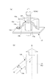
本発明に係る塗工装置200は、リング塗工法を採用した装置である。図3に示すように、塗工装置200には、架台5の上に略垂直に立設するコラム6が取り付けられている。図中の左右に位置する各コラム6上部には、精密ボールネジ7が略垂直に取り付けられている。そして、精密ボールネジ7と平行にリニアガイド8が1本ずつ各コラム6に取り付けられている。図中左側のコラム6には、リニアガイド8及び精密ボールネジ7と連結したLMガイド9が上下に分かれて2つ設けられている。これらのLMガイド9は、サーボモータ10の回転運動がプーリ11を介して伝達されることによりリニアガイド8に沿って上下に昇降する。LMガイド9には、ブラケット14がそれぞれ取り付けられている。図中下側のブラケット14には、基体4aなどの円筒体12を下方から保持し固定するワーク下保持軸15が略垂直に取り付けられている。他方、図中上側のブラケット14には、円筒体12を上方から保持し固定するワーク上保持軸16が略垂直に取り付けられている。これらワーク下保持軸15とワーク上保持軸16とは互いに対向しかつ略同心になるように配置され、円筒体12を上下から挟持する。したがって、ワーク下保持軸15とワーク上保持軸16とに保持された円筒体12は、LMガイド9と共にサーボモータ10により図3の上下に移動し得る。
The
また、図中左側のコラム6には、円筒体12の外周面に液状ゴム混合物を塗布するためのリング形状の塗工ヘッド13が円筒体12の外周面に対向して配置されている。塗工ヘッド13は中央部に貫通孔13g(図4参照)を有してなり、その中心軸はワーク下保持軸15とワーク上保持軸16の移動方向と平行になるように支持される。また、塗工ヘッド13は、その中心軸の延長線上にワーク下保持軸15及びワーク上保持軸16の軸中心が位置づけられるように配置される。これにより、塗工ヘッド13の中心軸と貫通孔13gに通された円筒体12の中心軸とが略一致し、塗工ヘッド13の内周面と円筒体12の外周面との間に全周にわたって均一な幅の間隙が形成される。
In the left column 6 in the figure, a ring-shaped
塗工ヘッド13には、液状ゴム混合物の供給口17が接続されている。供給口17は、液状ゴム混合物が通される配管18を介して材料供給弁19に接続される。そして、右コラム6にはシリンジ20が設けられる他に、図示を省略した混合ミキサー、材料定量吐出装置、材料タンク等が設けられる。液状ゴム混合物は、材料タンクから材料定量吐出装置により一定量ずつ計量されて混合ミキサーで混合される。混合された液状ゴム混合物はシリンジ20に一旦充填された後に、シリンジ20から単位時間あたり一定量ずつ配管18及び材料供給弁19を経由して供給口17に送られる。
A liquid rubber
供給口17は塗工ヘッド13に接続されていることから、シリンジ20から供給口17に送られた液状ゴム混合物は塗工ヘッド13に供給される。塗工ヘッド13に供給された液状ゴム混合物は、図4(a)に示す塗工ヘッド13内の流路13eを通って、塗工ヘッド13の内面に環状に設けられた吐出口13fから吐出される。液状ゴム混合物を吐出する際には、塗工ヘッド13からの吐出量とシリンジ20からの液状ゴム混合物の供給量を一定に維持したうえで、円筒体12を図3の上方へと移動する。こうして塗工ヘッド13に対し円筒体12を移動させながら液状ゴム混合物を吐出することで、円筒体12の外周面全域に一定の厚さで液状ゴム混合物を塗布することができる。なお、円筒体12の外周面と塗工ヘッド13の内周面との間隙は、弾性層(例えば第二弾性層4cなど)の層厚以上であるのが好ましい。
Since the
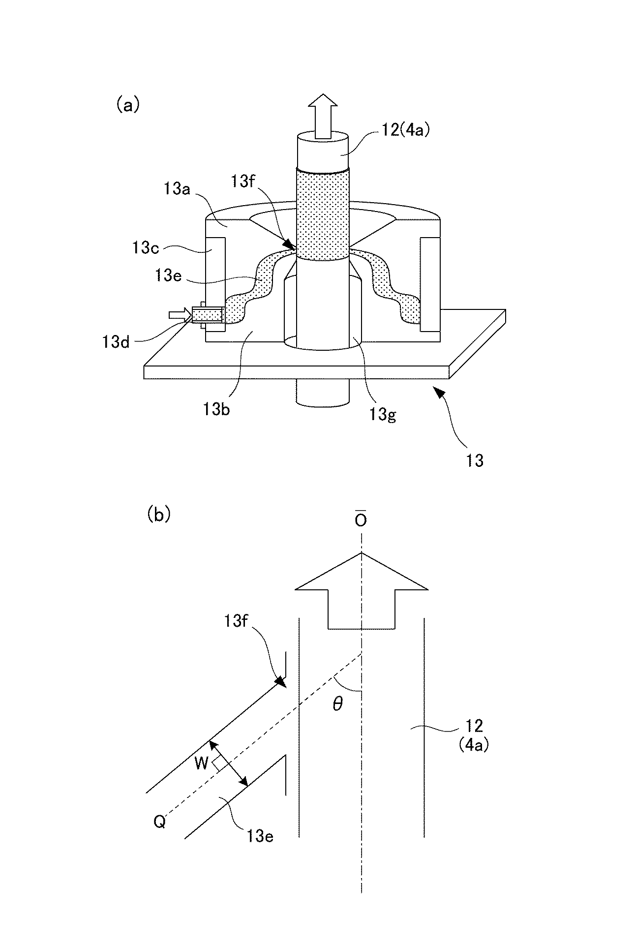
(塗工ヘッド)
塗工ヘッド13について説明する。図4(a)に示すように、塗工ヘッド13は大きく分けると、ヘッド上部部材13a、ヘッド下部部材13b、ヘッド外周部材13cにより構成されている。塗工ヘッド13は、中央部に孔を有する円筒状のヘッド上部部材13aとヘッド下部部材13bとを同軸に組み合わせて、これらを中空円筒形のヘッド外周部材13cにより外側から保持することによって形成される。勿論、これらは一体的に作られていてもよい。ヘッド上部部材13aとヘッド下部部材13bとが組み合わされることにより、塗工ヘッド13内に流路13eが形成されると共に、塗工ヘッド13の内周面の周方向全周にわたって環状に開口したスリット状の吐出口13fが形成される。すなわち、ヘッド上部部材13aとヘッド下部部材13bとを組み合わせたときに、これらの間に生ずる間隙が所定の流路13e及び吐出口13fを形成するように、予めヘッド上部部材13aとヘッド下部部材13bは互いに関連付けられた形状に形成される。ヘッド外周部材13cには材料注入口13dが設けられており、該材料注入口13dは供給口17(図3参照)に繋がれる。
(Coating head)
The
流路13eは材料注入口13dから吐出口13fへと続く液状ゴム混合物の一連の連続した通り道となる。すなわち、配管18及び材料供給弁19を経由して液状ゴム混合物が材料注入口13dに送り込まれると、送り込まれた液状ゴム混合物は塗工ヘッド13内の流路13eに流れ込む。流路13eに流れ込んだ液状ゴム混合物は、周方向にひろがりながら流路13eを満たしていく。液状ゴム混合物は流路13eを満たすと、塗工ヘッド13の内周面に形成された吐出口13fから押し出されるようにして吐出される。こうして、塗工ヘッド13は液体ゴム混合物を円筒体12に対して全方位から同時に吐出する。
The
塗工ヘッド13の吐出口13fは、液体ゴム混合物を吐出する方向が円筒体12の軸に対して傾斜するように、円筒体12の軸に対し所定の角度だけ傾けられて形成される。この角度は円筒体12の軸に対してあまりに緩い角度であったりあるいは急な角度であったりすると、非通紙部昇温の緩和に効果的である軸方向の熱伝導率が高い加圧ローラ(より具体的には第二弾性層4c)を形成することが難しくなる。そこで、図4(b)に示すように、吐出口13fの流路幅Wに直交する法線Qと、円筒体12の軸Oとのなす角度θ(以下、これを傾斜角と呼ぶ)が25°〜75°となるように、塗工ヘッド13の吐出口13fは形成される。言い換えるならば、少なくとも吐出口13f近傍の流路13eが円筒体12の軸Oに対して25°〜75°傾斜するように、塗工ヘッド13は形成されている。
The
上記の傾斜角θは、液状ゴム混合物が吐出口13fから円筒体12の軸方向に沿って流れやすい向きに液状ゴム混合物を吐出することの可能な角度である。例えば傾斜角θが75°を上回る角度である場合、液状ゴム混合物は円筒体12の軸方向に沿って流れ難くなる。この場合、液状ゴム混合物は吐出口13fから円筒体12の外周面に対し垂直に近い向きで吐出されることから、吐出された液状ゴム混合物は一旦円筒体12の外周面に向かい、その後に円筒体12の軸方向に沿って流れる。したがって、液状ゴム混合物に含まれる針状フィラーは円筒体12の厚み方向に配向されやすく、円筒体12の軸方向には配向されにくい。そうであると、非通紙部昇温の緩和に効果的である加圧ローラの軸方向の熱伝導率を高くすることが難しくなる。
The inclination angle θ is an angle at which the liquid rubber mixture can be discharged in a direction in which the liquid rubber mixture can easily flow from the
一方、傾斜角θが25°未満の角度である場合、液状ゴム混合物は吐出口13fから円筒体12の外周面に対し水平に近い向きで吐出されることから、吐出された液状ゴム混合物は円筒体12の軸方向に沿って流れる。したがって、液状ゴム混合物に含まれる針状フィラーは円筒体12の軸方向に配向されやすい。しかし、この場合、液状ゴム混合物が円筒体12の外周面に付着しにくくなり、弾性層を形成することが難しくなる。
On the other hand, when the inclination angle θ is less than 25 °, the liquid rubber mixture is discharged from the
既に述べたとおり、針状フィラーを液状シリコーンゴム等に混合した場合、針状フィラーは細長い繊維形状をしているため、基体4aへ吐出される液状ゴム混合物が流れる向きに配向されやすい。そのため、弾性層ひいては加圧ローラ4内における熱の流れをより大きくしたい向きに液状ゴム混合物を流すことによって、その方向への熱の流れを他方向への熱の流れより大きくすることができる。本実施例では、第二弾性層4cを形成する際の液状ゴム混合物の流れの向きを基体4aの軸方向とする。こうすることで、効率よく針状フィラーを軸方向に配向させて軸方向の熱伝導率を高めることができ、もって非通紙部から通紙部やローラ両端部へと効率的に熱を分散させることが可能となる。この点に鑑み、本実施例では吐出口13fの吐出方向を上述したように傾斜角25°〜75°となる向きにしている。
As already described, when the needle-like filler is mixed with liquid silicone rubber or the like, the needle-like filler has an elongated fiber shape, so that the liquid rubber mixture discharged to the
なお、上記塗工ヘッド13は、液状ゴム混合物を基体4aの外周面に対し斜めに吐出する吐出口13fの形成がしやすく、かつ溶剤等に侵されにくい材質のものが好ましい。この材質としては、例えばステンレス、鉄、アルミニウム、銅、真鍮等の金属やフッ素樹脂、アクリル樹脂、フェノール樹脂、ポリカーボネート、ポリエチレン、ポリスチレン等の樹脂があるが、加工精度の観点からステンレス等の鋼材を用いるのが好ましい。
The
[第二弾性層の形成工程]
加圧ローラ4の製造方法のうち特に第二弾性層4cの形成工程について説明する。まず、基体4aの外周に形成済みである第一弾性層4bの周面にプライマー(商品名:DY39−051、東レ・ダウコーニング株式会社製)を塗布して、例えば熱風循環式オーブンで180℃、30分間焼成する(プライマー処理)。プライマー処理後、基体4a(円筒体12)は塗工装置200のワーク下保持軸15とワーク上保持軸16によって軸が垂直に立てられた状態で保持される。
[Second elastic layer forming step]
Of the manufacturing method of the pressure roller 4, a process of forming the second
サーボモータ10を動作して基体4aを塗工開始位置まで降下した後に、サーボモータ10を反転動作して基体4aを例えば30mm/sの速度で上昇させる。基体4aを上昇させるのにあわせて、塗工ヘッド13の吐出口13fから層厚が例えば1mmになる一定の吐出量で液状ゴム混合物を吐出する。こうして基体4aを塗工ヘッド13に対して移動させながら、液状ゴム混合物を塗工ヘッド13内周面に設けてある吐出口13fから基体4aに向けて吐出することにより、基体4aの周方向及び軸方向の全域にわたって液状ゴム混合物を塗布していく。この際に、液状ゴム混合物は吐出口13fから基体4aの軸に対して傾斜した方向に吐出される。
After the
基体4aの全域にわたって液状ゴム混合物が塗布されると、基体4aを垂直保持状態から水平保持状態にし、基体4aを回転する。基体4aを垂直保持状態から水平保持状態に移行するのは、液状ゴム混合物を流動させて弾性層表面を平滑にするためである。基体4aは、例えば回転数60rpmで回転されながら加熱される。基体4aを回転させながら加熱するのは、液状ゴム混合物がダレてしまうのを防ぐため、また塗布された液状ゴム混合物を均一に加熱するためである。基体4aの表面温度が180℃になった状態を3分間維持すると、液状シリコーンゴムは硬化する(加熱硬化)。この加熱硬化のために用いる熱源は、液状ゴム混合物を非接触で加熱できる近赤外線ヒータ、遠赤外線セラミックヒータ、ランプ加熱ヒータ、UVヒータ等が望ましい。加熱温度は使用する液状ゴム混合物によって異なるが、硬化反応の生ずる100℃〜250℃程度の温度が好ましい。さらに、基体4aは200℃の熱風循環式オーブンにより4時間程度の間加熱される。これにより、液状シリコーンゴムは2次硬化する。こうして、第二弾性層4cが第一弾性層4bの周面に形成される。
When the liquid rubber mixture is applied over the entire area of the
[加圧ローラの評価]
以下、本発明に係る弾性ローラの製造方法によって形成される加圧ローラ4の評価について、後述する実施例1乃至実施例4、比較例1乃至比較例3を用いて説明する。
[Evaluation of pressure roller]
Hereinafter, evaluation of the pressure roller 4 formed by the elastic roller manufacturing method according to the present invention will be described with reference to Examples 1 to 4 and Comparative Examples 1 to 3 described later.
<熱伝導率>
本実施例では、評価のために熱伝導率を求める。熱伝導率は、熱拡散率から換算する。熱拡散率の計測には、温度可変型の温度波熱分析法によって熱拡散率を測定するタイプの装置を用いた。このタイプの装置として、例えば「ai−Phase Mobile2」(商品名、株式会社アイフェイズ製)の熱拡散率測定装置が挙げられる。この装置を用いて、図2(a)に示すような加圧ローラ4の周方向(x方向)及び加圧ローラ4の軸方向(y方向)及び加圧ローラ4の厚み方向(z方向)について、それぞれの熱拡散率を測定した。図2(b)に示すように、周方向(x方向)の熱拡散率測定には、yz面に切り込みを入れてx方向の厚みが1mm以下になるように切り出したものを被測定試料とした。軸方向(y方向)の熱拡散率測定には、zx面に切り込みを入れてy方向の厚みが1mm以下となるように切り出したものを被測定試料とした。厚み方向(z方向)の熱拡散率測定には、xy面に切り込みを入れてz方向の厚みが1mm以下となるように切り出したものを被測定試料とした。そして、これらの被測定試料を用いて温度設定50℃にて各方向毎に熱拡散率測定を5回ずつ行い、5回の平均値をそれぞれ周方向熱拡散率、軸方向熱拡散率、厚み方向熱拡散率とした。
<Thermal conductivity>
In this example, the thermal conductivity is obtained for evaluation. Thermal conductivity is converted from thermal diffusivity. For the measurement of the thermal diffusivity, a device of a type that measures the thermal diffusivity by a temperature variable thermal wave thermal analysis method was used. As this type of apparatus, for example, a thermal diffusivity measuring apparatus of “ai-
熱拡散率から熱伝導率を換算するには、密度と比熱容量の各値が必要である。密度の計測には、例えば「Accupyc 1330」(商品名、株式会社島津製作所製)といった乾式自動密度計を用いる。また、比熱容量の計測には、例えば「DSC823」(商品名、メトラー・トレド株式会社製)といった示差走査型熱量測定装置を用いる。このときに比熱容量を比較するために基準とする、比熱容量が既知の物質にはサファイアを用いた。この測定装置による比熱容量測定を5回行って、5回の平均値を比熱容量とした。熱伝導率λは、こうして得られた密度と比熱容量とを乗算し、さらにその結果に上述の熱拡散率を乗算して求めた。 In order to convert thermal conductivity from thermal diffusivity, each value of density and specific heat capacity is required. For the measurement of the density, for example, a dry automatic densimeter such as “Acupyc 1330” (trade name, manufactured by Shimadzu Corporation) is used. For the measurement of specific heat capacity, for example, a differential scanning calorimeter such as “DSC823” (trade name, manufactured by METTLER TOLEDO Co., Ltd.) is used. At this time, sapphire was used as a material having a known specific heat capacity as a reference for comparing the specific heat capacities. Specific heat capacity measurement with this measuring apparatus was performed 5 times, and the average value of 5 times was defined as the specific heat capacity. The thermal conductivity λ was obtained by multiplying the density thus obtained by the specific heat capacity and further multiplying the result by the above-mentioned thermal diffusivity.
<軸配向性及び配向均一性の指標>
第二弾性層4c内で針状フィラーが軸方向に沿って配向されているかの評価には、軸配向率「%λy」を用いた。軸配向率「%λy」は以下の式1により求まる。
軸配向率「%λy」=λy×100/(λx+λy+λz)(%)・・・式1
<Indices of axial orientation and orientation uniformity>
The axial orientation rate “% λy” was used for evaluating whether the needle-like filler is oriented along the axial direction in the second
Axial orientation ratio “% λy” = λy × 100 / (λx + λy + λz) (%) Equation 1
ここで、λxは第二弾性層4cの周方向の熱伝導率、λyは第二弾性層4cの軸方向の熱伝導率、λzは第二弾性層4cの厚み方向の熱伝導率である。この軸配向率「%λy」が高いほど、第二弾性層4c内で多くの針状フィラーが軸方向に配向されているといえる。
Here, λx is the thermal conductivity in the circumferential direction of the second
第二弾性層4cの周方向及び軸方向の全域にわたる針状フィラーの配向均一性の評価には、軸配向率の変動幅「Δ%λy」を用いた。この軸配向率の変動幅「Δ%λy」は、ローラ両端部及び中央部に位置する任意の点(3点)と、これら各点に対し周方向180°反対側に位置する点(3点)の計6点それぞれの軸配向率「%λy」のうち、最大の軸配向率と最小の軸配向率との差である。この差が小さいほど、第二弾性層4cの全域にわたってどの箇所においても針状フィラーが軸方向に略同じ割合で配向されているといえる。
The variation width “Δ% λy” of the axial orientation ratio was used to evaluate the orientation uniformity of the needle-like filler over the entire circumferential direction and the axial direction of the second
<評価結果>
後述する実施例1乃至実施例4の加圧ローラ、及び比較例1乃至比較例3の加圧ローラについて、第二弾性層4cの軸方向熱伝導率、軸配向率、軸配向率の変動幅を表1に示す。
<Evaluation results>
About the pressure roller of Example 1 thru | or Example 4 mentioned later, and the pressure roller of Comparative Example 1 thru | or Comparative Example 3, the fluctuation range of the axial direction thermal conductivity of the 2nd
実施例1乃至実施例4の加圧ローラ、及び比較例1乃至比較例3の加圧ローラはすべて共通に、基体4aに外径φ22mmの鉄製の芯金を用いた。また、第一弾性層4bは熱伝導率が0.24W/(m・k)のシリコーンゴムを用いて形成し、その厚みを3mmとした。第一弾性層4bを形成するために基体4aの周面に塗布するプライマーは、「DY39−051」(商品名、東レ・ダウコーニング株式会社製)を用いた。離型層4dは、第二弾性層4c上に厚み50μmのPFAチューブを被覆した。第二弾性層4cと離型層4dとを接着する接着剤は、「SE1819CV」(商品名、東レ・ダウコーニング社製)を用いた。
The pressure roller of Example 1 to Example 4 and the pressure roller of Comparative Example 1 to Comparative Example 3 were all in common using an iron cored bar having an outer diameter of φ22 mm for the
(実施例1の第二弾性層)
実施例1では、第二弾性層4c用の液状ゴム混合物として、重量平均分子量が5万である付加反応架橋型液状シリコーンゴムに針状フィラーを体積比19.8%の割合で混合したものを使用した。針状フィラーは、平均繊維長が9μm、平均繊維長が100μm、熱伝導率λが900W/(m・k)のピッチ系炭素繊維(商品名「GRANOCミルドファイバー(XN−100−10M)」、日本グラファイトファイバー株式会社製)を用いた。第二弾性層4cの形成には、図4に示した塗工ヘッド13を有する図3に示した塗工装置200を用いた。塗工ヘッド上部および下部の内直径は30.0mm、環状スリット内部の最狭幅は0.5mm、傾斜角θは45°とした。
(Second elastic layer of Example 1)
In Example 1, as a liquid rubber mixture for the second
(実施例2の第二弾性層)
実施例2では、第二弾性層4c用の液状ゴム混合物として、重量平均分子量が5万である付加反応架橋型液状シリコーンゴムに針状フィラーを体積比16.0%の割合で混合したものを使用した。針状フィラーは、平均繊維長が9μm、平均繊維長が200μm、熱伝導率λが900W/(m・k)のピッチ系炭素繊維(商品名「GRANOCミルドファイバー(XN−100−20M)」、日本グラファイトファイバー株式会社製)を用いた。第二弾性層4cの形成には実施例1と同様に、図4に示した塗工ヘッドを有する図3に示した塗工装置を用いた。ただし、環状スリット内部の最狭幅は1.0mm、傾斜角θは45°とした。
(Second elastic layer of Example 2)
In Example 2, as a liquid rubber mixture for the second
(実施例3の第二弾性層)
実施例3では、第二弾性層4c用の液状ゴム混合物として、実施例1と同じものを使用した。また、第二弾性層4cの形成には実施例1と同様に、図4に示した塗工ヘッドを有する図3に示した塗工装置を用いた。ただし、環状スリット内部の最狭幅は0.5mm、傾斜角θは75°とした。
(Second elastic layer of Example 3)
In Example 3, the same liquid rubber mixture as used in Example 1 was used as the liquid rubber mixture for the second
(実施例4の第二弾性層)
実施例4では、第二弾性層4c用の液状ゴム混合物として、実施例2と同じものを使用した。また、第二弾性層4cの形成には実施例1と同様に、図4の塗工ヘッド13を有する図3に示した塗工装置200を用いた。ただし、環状スリット内部の最狭幅は1.0mm、傾斜角θは25°とした。
(Second elastic layer of Example 4)
In Example 4, the same liquid rubber mixture for the second
(比較例1の第二弾性層)
比較例1では、第二弾性層4c用の液状ゴム混合物として実施例1と同様の液状ゴム混合物を用いた。第二弾性層4cの形成には、リング塗工法を採用した従来の塗工装置を用いた。従来の塗工装置は、液体ゴム混合物を基体4aの軸に対して垂直に吐出する塗工ヘッドを備える。言い換えれば、従来の塗工装置には、塗工ヘッドの吐出口が円筒体12の軸に対して垂直つまりは傾斜角θが90°となるように形成されている。なお、塗工ヘッド上部および下部の内直径が30.0mm、環状スリット内部の最狭幅が0.5mmのものを用いた。
(Second elastic layer of Comparative Example 1)
In Comparative Example 1, the same liquid rubber mixture as in Example 1 was used as the liquid rubber mixture for the second
(比較例2の第二弾性層)
比較例2では、第二弾性層4c用の液状ゴム混合物として、重量平均分子量が5万である付加反応架橋型の液状シリコーンゴムに針状フィラーを体積比25.4%の割合で混合したものを使用した。針状フィラーには、実施例1と同じピッチ系炭素繊維(商品名「GRANOCミルドファイバー(XN−100−10M)」、日本グラファイトファイバー株式会社製)を用いた。そして、比較例2では、第二弾性層4cの形成にリング塗工法でなく注型法を用いた。つまり、円筒状の金型の内面にPFAチューブを予めセットしたものに対し、該金型の中央にプライマー処理済みの第一弾性層4bを形成済みの基体4aをセットする。そして、この第一弾性層4bとPFAチューブとの間に上記の液状ゴム混合物を流し込み、金型ごと200℃の熱風循環式オーブン中で加熱硬化する。硬化後、金型を脱型して基体4a上に第一弾性層4b、第二弾性層4c、PFAチューブ(離型層4d)が積層された弾性ローラを取り出す。この弾性ローラを200℃の熱風循環式オーブン中でさらに4時間加熱すると、第二弾性層4cは2次硬化する。このようにして、比較例2の第二弾性層4cは形成される。
(Second elastic layer of Comparative Example 2)
In Comparative Example 2, as a liquid rubber mixture for the second
(比較例3の第二弾性層)
比較例3では、第二弾性層4c用の液状ゴム混合物として、重量平均分子量が5万である付加反応架橋型の液状シリコーンゴムに針状フィラーを体積比9.0%の割合で混合したものを使用した。比較例3では、針状フィラーとして平均繊維長が9μm、平均繊維長が250μm、熱伝導率が900W/(m・k)のピッチ系炭素繊維(商品名「GRANOCミルドファイバー(XN−100−25M)」、日本グラファイトファイバー株式会社製)を用いた。そして、比較例3では比較例2と同様に、第二弾性層4cの形成に注型法を用いた。
(Second elastic layer of Comparative Example 3)
In Comparative Example 3, as a liquid rubber mixture for the second
比較例1の結果をみると、比較例1の第二弾性層4cの軸方向の熱伝達率「λy」は1.5W/(m・k)、軸配向率「%λy」は29.7%、軸配向率の変動幅「Δ%λy」は4.5%である。比較例1の第二弾性層4cは実施例と同じリング塗工法を用いて形成したが、その軸配向率は29.7%と低い値にとどまっている。これは、従来の塗工装置では塗工ヘッドの吐出口が基体4aの軸に対して90°垂直向きに形成されていることによる。つまり、液体ゴム混合物は基体4aの軸に対して垂直に吐出され、液体ゴム混合物に含まれる針状フィラーは軸方向に配向され難いためである。軸配向率が低ければ軸方向の熱伝導率も低くなって、比較例1の第二弾性層4cでは1.5W/(m・k)である。したがって、比較例1の加圧ローラは非通紙部昇温の抑制の効果が低い。
Looking at the results of Comparative Example 1, the heat transfer coefficient “λy” in the axial direction of the second
比較例2の結果をみると、比較例2の第二弾性層4cの軸方向の熱伝達率「λy」は5.3W/(m・k)、軸配向率「%λy」は65.9%、軸配向率の変動幅「Δ%λy」は18.7%である。比較例2では注型法を用いて第二弾性層4cを形成したが、その軸配向率は65.9%と高い。これは、注型法では液体ゴム混合物に含まれる針状フィラーが軸方向に配向されやすいことによる。そして、軸配向率が高ければ軸方向の熱伝導率も高くなって、比較例2の第二弾性層4cでは5.3W/(m・k)である。したがって、比較例2の加圧ローラは非通紙部昇温の抑制の効果が高い。その一方で、軸配向率の変動幅は約20%程度であることからすると、第二弾性層4cの周方向及び軸方向の全域にわたって針状フィラーは同じように配向されていない。つまり、針状フィラーの多くは軸方向に配向されているが、その配向は第二弾性層4cの全域にわたってどの箇所でも略同じでなく箇所によって差が生じている。
Looking at the results of Comparative Example 2, the heat transfer coefficient “λy” in the axial direction of the second
比較例3の結果をみると、比較例3の第二弾性層4cの軸方向の熱伝達率「λy」は2.4W/(m・k)、軸配向率「%λy」は46.6%、軸配向率の変動幅「Δ%λy」は17.0である。比較例3では比較例2と同様に注型法を用いて第二弾性層4cを形成したが、その軸配向率は46.6%と比較例2に比べると低い。これは、比較例2に比べて液状シリコーンゴムに対する針状フィラーの分散含有量を減らしたことによる。その一方で、比較例2に比して針状フィラーの分散含有量を減らしたにもかかわらず、軸配向率の変動幅は比較例2とあまり変わっていない。つまり、針状フィラーの分散含有量を減らしただけでは、針状フィラーの配向の割合を略同じにすることができず、単に軸方向の熱伝導率を低くしてしまうだけである。
Looking at the results of Comparative Example 3, the heat transfer coefficient “λy” in the axial direction of the second
これに対し、実施例1〜実施例4の結果をみると、実施例1の第二弾性層4cの軸方向の熱伝達率「λy」は2.8W/(m・k)、軸配向率「%λy」は65.6%、軸配向率の変動幅「Δ%λy」は2.7である。実施例2の第二弾性層4cの軸方向の熱伝達率「λy」は4.6W/(m・k)、軸配向率「%λy」は71.6%、軸配向率の変動幅「Δ%λy」は2.6である。実施例3の第二弾性層4cの軸方向の熱伝達率「λy」は2.7W/(m・k)、軸配向率「%λy」は53.8%、軸配向率の変動幅「Δ%λy」は3.6である。実施例4の形成された第二弾性層4cの軸方向の熱伝達率「λy」は4.8W/(m・k)、軸配向率「%λy」は75.3%、軸配向率の変動幅「Δ%λy」は2.7である。
On the other hand, looking at the results of Examples 1 to 4, the heat transfer coefficient “λy” in the axial direction of the second
実施例1〜実施例4ではいずれも軸配向率が50%以上であり、かつ軸配向率の変動幅が4%未満である。軸配向率は50%以上であれば、非通紙部昇温の発生抑制に十分なだけの熱伝導率を付与することができているので問題ない。そして、実施例1〜実施例4の特徴的な点は、比較例と異なり軸配向率が50%以上と比較的に高くとも軸配向率の変動幅が4%未満に収まっている点にある。つまり、実施例1〜実施例4の第二弾性層4cでは、針状フィラーは軸方向に配向されるが故に軸方向に高い熱伝導率を付与できている。それだけでなく、針状フィラーの軸方向への配向の割合が全域にわたって略同じであるが故に、弾性層全域にわたって同程度の熱伝導率を付与できている。
In all of Examples 1 to 4, the axial orientation rate is 50% or more, and the fluctuation range of the axial orientation rate is less than 4%. If the axial orientation ratio is 50% or more, there is no problem because sufficient thermal conductivity can be imparted to suppress the occurrence of non-sheet passing portion temperature rise. And the characteristic point of Examples 1 to 4 is that, unlike the comparative example, the axial orientation ratio is relatively high, 50% or higher, but the fluctuation range of the axial orientation ratio is less than 4%. . That is, in the 2nd
以上のように、本発明に係る弾性ローラの製造方法では、基体4aと塗工ヘッド13とを軸方向に移動させつつ、吐出口13fから針状フィラーを含む液状ゴム混合物を基体4aの軸に対して25°〜75°の範囲で傾斜した方向に吐出するようにした。そうするために、塗工ヘッド13には、流路幅Wに直交する法線が基体4aの軸に対して傾斜角25°〜75°だけ傾斜するように吐出口13fが形成されている。これにより、吐出された液状ゴム混合物の流動向きが基体4aの軸方向に沿う方向となる。そのため、針状フィラーが基体4aの軸方向に配向されながらかつ全域にわたって略同じ割合に配向されながら液状ゴム混合物は基体4aの外周面に塗布されることになる。こうして、針状フィラーが基体4aの少なくとも軸方向に配向されかつその配向の割合が全域にわたってどの箇所でも略同じである弾性層を有する弾性ローラを形成することができる。この弾性層は、全域にわたって軸方向の熱伝導性が同じ程度に高い特性を持つ。
As described above, in the elastic roller manufacturing method according to the present invention, the liquid rubber mixture containing the needle-like filler is discharged from the
なお、上述した実施例では、内周面が全周にわたって環状に開口されたスリット状の吐出口13fを有した塗工ヘッド13を例に示したがこれに限らず、内周面の一部がスリット状に開口された1乃至複数の吐出口を有した塗工ヘッド13であってもよい。この場合には、液状ゴム混合物を基体4aに向けて吐出する際に、基体4aと塗工ヘッド13とを相対的に回転させることによって、基体4aの周方向に均一に液状ゴム混合物を塗布する。勿論、基体4aを塗工ヘッド13に対して上昇させることで、基体4aの周方向だけでなく軸方向に対しても液状ゴム混合物を塗布するのは言うまでもない。なお、塗工ヘッド13の吐出口13fはスリット状に形成することに限らず、例えば多数の小さな孔を少なくとも周方向に並べて形成してもよい。
In the above-described embodiment, the
なお、上述した実施例では加圧ローラを例に説明したがこれに限らない。例えば、加圧ローラと圧接して定着ニップ部を形成する定着ローラなどにも適用することができる。あるいは、ポリイミド、ポリアミドイミド、ポリエーテルエーテルケトン等の薄肉耐熱性樹脂もしくはステンレスやニッケル等の薄肉金属からなる無端ベルト状の加圧ベルトや定着ベルトなどであっても本発明を適用することは可能である。 In the above-described embodiment, the pressure roller is described as an example, but the present invention is not limited to this. For example, the present invention can also be applied to a fixing roller that forms a fixing nip portion in pressure contact with a pressure roller. Alternatively, the present invention can be applied to an endless belt-like pressure belt or fixing belt made of a thin heat-resistant resin such as polyimide, polyamideimide, polyetheretherketone, or a thin metal such as stainless steel or nickel. It is.
1…ヒータ、2…ヒータホルダ、3…定着ベルト、3a…基材、3b…ベルト弾性層
3c…表層、4…加圧ローラ、4a…基体、4b…第一弾性層、4c…第二弾性層
4d…離型層、13…塗工ヘッド、13e…流路、13f…吐出口、13g…貫通孔
100…定着装置、200…塗工装置、P…記録材、T…未定着トナー
DESCRIPTION OF SYMBOLS 1 ... Heater, 2 ... Heater holder, 3 ... Fixing belt, 3a ... Base material, 3b ... Belt
Claims (8)
前記基体と前記塗工ヘッドとを少なくとも軸方向に相対的に移動させつつ、前記吐出口から前記液状材料を前記基体の軸に対して傾斜した方向に吐出して、該液状材料を前記基体の外周面に塗布する工程を有することを特徴とする弾性ローラの製造方法。 An elastic layer is formed on the outer peripheral surface of the substrate by using a coating head that discharges a liquid material mixed with needle-like filler from the discharge port arranged facing the outer peripheral surface of the cylindrical substrate toward the substrate. A method for producing an elastic roller comprising:
The liquid material is discharged from the discharge port in a direction inclined with respect to the axis of the substrate, while relatively moving the substrate and the coating head at least in the axial direction. A method for producing an elastic roller, comprising a step of applying to an outer peripheral surface.
前記塗工ヘッドは、前記吐出口からの吐出方向が前記基体の軸に対して傾斜するように形成されてなることを特徴とする塗工装置。 A holding means for holding a cylindrical substrate, a coating head having a discharge port disposed to face the outer peripheral surface of the substrate, and the substrate and the coating head are moved relatively at least in the axial direction. Moving means, and discharging the liquid material mixed with the needle filler from the discharge port while relatively moving the base and the coating head, and applying the liquid material to the outer peripheral surface of the base In coating equipment,
The coating apparatus, wherein the coating head is formed so that a discharge direction from the discharge port is inclined with respect to an axis of the substrate.
Priority Applications (1)
| Application Number | Priority Date | Filing Date | Title |
|---|---|---|---|
| JP2013254130A JP2015114367A (en) | 2013-12-09 | 2013-12-09 | Method of manufacturing elastic roller and coating device |
Applications Claiming Priority (1)
| Application Number | Priority Date | Filing Date | Title |
|---|---|---|---|
| JP2013254130A JP2015114367A (en) | 2013-12-09 | 2013-12-09 | Method of manufacturing elastic roller and coating device |
Publications (1)
| Publication Number | Publication Date |
|---|---|
| JP2015114367A true JP2015114367A (en) | 2015-06-22 |
Family
ID=53528245
Family Applications (1)
| Application Number | Title | Priority Date | Filing Date |
|---|---|---|---|
| JP2013254130A Pending JP2015114367A (en) | 2013-12-09 | 2013-12-09 | Method of manufacturing elastic roller and coating device |
Country Status (1)
| Country | Link |
|---|---|
| JP (1) | JP2015114367A (en) |
Cited By (3)
| Publication number | Priority date | Publication date | Assignee | Title |
|---|---|---|---|---|
| JP2020034154A (en) * | 2018-08-28 | 2020-03-05 | キヤノン株式会社 | Pressure roller for fixing device, fixing device, and image forming device |
| US10809654B2 (en) | 2018-08-28 | 2020-10-20 | Canon Kabushiki Kaisha | Pressure roller for fixing apparatus, fixing apparatus and image forming apparatus |
| US12181822B2 (en) | 2022-12-22 | 2024-12-31 | Fujifilm Business Innovation Corp. | Tubular fixing member, fixing device, and image forming apparatus |
-
2013
- 2013-12-09 JP JP2013254130A patent/JP2015114367A/en active Pending
Cited By (4)
| Publication number | Priority date | Publication date | Assignee | Title |
|---|---|---|---|---|
| JP2020034154A (en) * | 2018-08-28 | 2020-03-05 | キヤノン株式会社 | Pressure roller for fixing device, fixing device, and image forming device |
| US10809654B2 (en) | 2018-08-28 | 2020-10-20 | Canon Kabushiki Kaisha | Pressure roller for fixing apparatus, fixing apparatus and image forming apparatus |
| JP7374641B2 (en) | 2018-08-28 | 2023-11-07 | キヤノン株式会社 | Pressure roller for fixing device, fixing device, and image forming device |
| US12181822B2 (en) | 2022-12-22 | 2024-12-31 | Fujifilm Business Innovation Corp. | Tubular fixing member, fixing device, and image forming apparatus |
Similar Documents
| Publication | Publication Date | Title |
|---|---|---|
| US9335690B2 (en) | Pressing roller and image heating apparatus having same | |
| JP6544993B2 (en) | Manufacturing device for fixing member | |
| JP5863488B2 (en) | Endless belt and image heating device | |
| JP6347727B2 (en) | Fixing member, fixing device, and image forming apparatus | |
| KR100935486B1 (en) | Image heating apparatus and rotatable heating member used in the apparatus | |
| JP2016029462A (en) | Fixing member | |
| JP2015055655A (en) | Pressure rotating body, image heating device using the same, image forming apparatus, and manufacturing method of pressure rotating body | |
| US20130011157A1 (en) | Heat fixing device | |
| US10281858B2 (en) | Roller with elastic layers having different indentation elastic moduli, and fixing device having roller | |
| JP2012234151A (en) | Roller used for fixing device, and image heating apparatus provided with the roller | |
| US20200159147A1 (en) | Method for producing fixing member | |
| JP2015114367A (en) | Method of manufacturing elastic roller and coating device | |
| JP4701316B2 (en) | Endless metal belt, endless belt for electrophotography, fixing device, and electrophotographic image forming apparatus | |
| JP2014142406A (en) | Pressing member, fixing member, and image forming apparatus | |
| JP2009045577A (en) | Fluorine resin film forming method and film forming product thereof | |
| JP2017097028A (en) | Fixing member | |
| US6862424B2 (en) | Image heating apparatus | |
| JP2019028182A (en) | Fixing belt and fixing device | |
| JP2019012171A (en) | Fixation member and heating fixation device | |
| JP2016024218A (en) | Nip part formation member, fixation device, and production method of nip part formation member | |
| JP2004138957A (en) | Toner fixing member | |
| JP2007171280A (en) | Seamless cylindrical member and fixing device | |
| JP2015102618A (en) | Rotating body, pressure body, method for manufacturing the same, and fixing device | |
| JP2019028183A (en) | Elastic roller and fixing device | |
| JP5430412B2 (en) | Method for producing elastic roller containing glass hollow filler |