JP2015114333A - Method and device for determining gas turbine dampening cone inner diameter - Google Patents
Method and device for determining gas turbine dampening cone inner diameter Download PDFInfo
- Publication number
- JP2015114333A JP2015114333A JP2014252368A JP2014252368A JP2015114333A JP 2015114333 A JP2015114333 A JP 2015114333A JP 2014252368 A JP2014252368 A JP 2014252368A JP 2014252368 A JP2014252368 A JP 2014252368A JP 2015114333 A JP2015114333 A JP 2015114333A
- Authority
- JP
- Japan
- Prior art keywords
- displacement
- inner diameter
- cone
- indicator
- contact surface
- Prior art date
- Legal status (The legal status is an assumption and is not a legal conclusion. Google has not performed a legal analysis and makes no representation as to the accuracy of the status listed.)
- Pending
Links
- 238000000034 method Methods 0.000 title claims abstract description 32
- 238000006073 displacement reaction Methods 0.000 claims abstract description 109
- 238000005259 measurement Methods 0.000 claims abstract description 48
- 238000013016 damping Methods 0.000 claims description 100
- 238000007689 inspection Methods 0.000 description 5
- 230000000712 assembly Effects 0.000 description 2
- 238000000429 assembly Methods 0.000 description 2
- 230000008878 coupling Effects 0.000 description 2
- 238000010168 coupling process Methods 0.000 description 2
- 238000005859 coupling reaction Methods 0.000 description 2
- 239000011435 rock Substances 0.000 description 2
- 230000004323 axial length Effects 0.000 description 1
- 239000011324 bead Substances 0.000 description 1
- 230000005540 biological transmission Effects 0.000 description 1
- 238000010276 construction Methods 0.000 description 1
- 230000014509 gene expression Effects 0.000 description 1
- 230000005484 gravity Effects 0.000 description 1
- 238000009434 installation Methods 0.000 description 1
- 230000013011 mating Effects 0.000 description 1
- 238000012806 monitoring device Methods 0.000 description 1
- 238000011144 upstream manufacturing Methods 0.000 description 1
Images
Classifications
-
- G—PHYSICS
- G01—MEASURING; TESTING
- G01B—MEASURING LENGTH, THICKNESS OR SIMILAR LINEAR DIMENSIONS; MEASURING ANGLES; MEASURING AREAS; MEASURING IRREGULARITIES OF SURFACES OR CONTOURS
- G01B21/00—Measuring arrangements or details thereof, where the measuring technique is not covered by the other groups of this subclass, unspecified or not relevant
- G01B21/10—Measuring arrangements or details thereof, where the measuring technique is not covered by the other groups of this subclass, unspecified or not relevant for measuring diameters
- G01B21/14—Measuring arrangements or details thereof, where the measuring technique is not covered by the other groups of this subclass, unspecified or not relevant for measuring diameters internal diameters
-
- F—MECHANICAL ENGINEERING; LIGHTING; HEATING; WEAPONS; BLASTING
- F02—COMBUSTION ENGINES; HOT-GAS OR COMBUSTION-PRODUCT ENGINE PLANTS
- F02C—GAS-TURBINE PLANTS; AIR INTAKES FOR JET-PROPULSION PLANTS; CONTROLLING FUEL SUPPLY IN AIR-BREATHING JET-PROPULSION PLANTS
- F02C7/00—Features, components parts, details or accessories, not provided for in, or of interest apart form groups F02C1/00 - F02C6/00; Air intakes for jet-propulsion plants
- F02C7/20—Mounting or supporting of plant; Accommodating heat expansion or creep
-
- F—MECHANICAL ENGINEERING; LIGHTING; HEATING; WEAPONS; BLASTING
- F01—MACHINES OR ENGINES IN GENERAL; ENGINE PLANTS IN GENERAL; STEAM ENGINES
- F01D—NON-POSITIVE DISPLACEMENT MACHINES OR ENGINES, e.g. STEAM TURBINES
- F01D25/00—Component parts, details, or accessories, not provided for in, or of interest apart from, other groups
- F01D25/28—Supporting or mounting arrangements, e.g. for turbine casing
-
- F—MECHANICAL ENGINEERING; LIGHTING; HEATING; WEAPONS; BLASTING
- F01—MACHINES OR ENGINES IN GENERAL; ENGINE PLANTS IN GENERAL; STEAM ENGINES
- F01D—NON-POSITIVE DISPLACEMENT MACHINES OR ENGINES, e.g. STEAM TURBINES
- F01D25/00—Component parts, details, or accessories, not provided for in, or of interest apart from, other groups
- F01D25/28—Supporting or mounting arrangements, e.g. for turbine casing
- F01D25/285—Temporary support structures, e.g. for testing, assembling, installing, repairing; Assembly methods using such structures
-
- F—MECHANICAL ENGINEERING; LIGHTING; HEATING; WEAPONS; BLASTING
- F02—COMBUSTION ENGINES; HOT-GAS OR COMBUSTION-PRODUCT ENGINE PLANTS
- F02C—GAS-TURBINE PLANTS; AIR INTAKES FOR JET-PROPULSION PLANTS; CONTROLLING FUEL SUPPLY IN AIR-BREATHING JET-PROPULSION PLANTS
- F02C7/00—Features, components parts, details or accessories, not provided for in, or of interest apart form groups F02C1/00 - F02C6/00; Air intakes for jet-propulsion plants
- F02C7/24—Heat or noise insulation
-
- G—PHYSICS
- G01—MEASURING; TESTING
- G01B—MEASURING LENGTH, THICKNESS OR SIMILAR LINEAR DIMENSIONS; MEASURING ANGLES; MEASURING AREAS; MEASURING IRREGULARITIES OF SURFACES OR CONTOURS
- G01B5/00—Measuring arrangements characterised by the use of mechanical techniques
- G01B5/08—Measuring arrangements characterised by the use of mechanical techniques for measuring diameters
- G01B5/12—Measuring arrangements characterised by the use of mechanical techniques for measuring diameters internal diameters
-
- G—PHYSICS
- G01—MEASURING; TESTING
- G01M—TESTING STATIC OR DYNAMIC BALANCE OF MACHINES OR STRUCTURES; TESTING OF STRUCTURES OR APPARATUS, NOT OTHERWISE PROVIDED FOR
- G01M15/00—Testing of engines
- G01M15/14—Testing gas-turbine engines or jet-propulsion engines
-
- F—MECHANICAL ENGINEERING; LIGHTING; HEATING; WEAPONS; BLASTING
- F01—MACHINES OR ENGINES IN GENERAL; ENGINE PLANTS IN GENERAL; STEAM ENGINES
- F01D—NON-POSITIVE DISPLACEMENT MACHINES OR ENGINES, e.g. STEAM TURBINES
- F01D5/00—Blades; Blade-carrying members; Heating, heat-insulating, cooling or antivibration means on the blades or the members
- F01D5/02—Blade-carrying members, e.g. rotors
- F01D5/10—Anti- vibration means
-
- Y—GENERAL TAGGING OF NEW TECHNOLOGICAL DEVELOPMENTS; GENERAL TAGGING OF CROSS-SECTIONAL TECHNOLOGIES SPANNING OVER SEVERAL SECTIONS OF THE IPC; TECHNICAL SUBJECTS COVERED BY FORMER USPC CROSS-REFERENCE ART COLLECTIONS [XRACs] AND DIGESTS
- Y02—TECHNOLOGIES OR APPLICATIONS FOR MITIGATION OR ADAPTATION AGAINST CLIMATE CHANGE
- Y02T—CLIMATE CHANGE MITIGATION TECHNOLOGIES RELATED TO TRANSPORTATION
- Y02T50/00—Aeronautics or air transport
- Y02T50/60—Efficient propulsion technologies, e.g. for aircraft
Landscapes
- Engineering & Computer Science (AREA)
- Chemical & Material Sciences (AREA)
- Combustion & Propulsion (AREA)
- Mechanical Engineering (AREA)
- General Engineering & Computer Science (AREA)
- Physics & Mathematics (AREA)
- General Physics & Mathematics (AREA)
- Life Sciences & Earth Sciences (AREA)
- General Life Sciences & Earth Sciences (AREA)
- A Measuring Device Byusing Mechanical Method (AREA)
- Turbine Rotor Nozzle Sealing (AREA)
- Length Measuring Devices With Unspecified Measuring Means (AREA)
Abstract
Description
本発明は、ガスタービンエンジンの略リング状の減衰コーンの内径を測定する方法および装置に関する。特に、本発明は、球状または別の凸状の内径面形状を有する減衰コーンの内径を測定する方法および装置にも関する。 The present invention relates to a method and apparatus for measuring the inner diameter of a generally ring-shaped damping cone of a gas turbine engine. In particular, the present invention also relates to a method and apparatus for measuring the inner diameter of a damping cone having a spherical or another convex inner diameter surface shape.
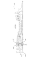
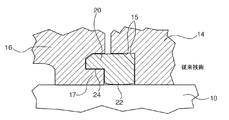
減衰コーンは、リング状の構成部分である。リング状の構成部分は、ガスタービンエンジンのロータタイロッドとタービンディスク列との間において半径方向および軸方向に配置され、各列をロータに沿って連続的に連結し、かつディスク列とロータタイロッドとの間の境界の半径方向の同心性を維持する。ガスタービンエンジンの直径、軸方向長さおよび回転質量が大きいため、回転機械の振動を最小化するには、減衰コーンを、均一な半径の同心状の内径が数10マイクロメートル内の公差仕様内になるように精密に加工する必要がある。減衰コーンは、内径面のピークにおいてロータタイロッドとの一定半径の円形線状の当接関係を形成するために、球状または別の凸状の内径面形状を有することが多い。図1および図2において、ガスタービンエンジン10は、回転可能に取り付けられたロータタイロッド12を有しており、ロータタイロッド12には、対応するタービン列を形成する、隣り合う軸方向に対向するタービンディスク14および16が取り付けられている。上流のタービンディスク16は、タービンディスク溝17を形成しており、下流のタービンディスク14はタービンディスク肩部15を形成している。
The damping cone is a ring-shaped component. Ring-shaped components are disposed radially and axially between the rotor tie rods and turbine disk rows of the gas turbine engine, continuously connecting each row along the rotor, and the disk rows and rotor tie rods. Maintain the radial concentricity of the boundary between. Due to the large diameter, axial length and rotating mass of the gas turbine engine, to minimize the vibration of rotating machinery, the damping cone should be within tolerance specifications with a concentric inner diameter of uniform radius within tens of micrometers. It is necessary to process precisely to become. Damping cones often have a spherical or another convex inner diameter surface shape to form a constant radius circular linear contact relationship with the rotor tie rod at the inner diameter surface peak. 1 and 2, a
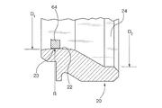
図2および図4により明確に示されるように、リング状の減衰コーン20は、比較的大きい半径Rの球状の凸状内径面22を形成している。球状半径の高点23は、ロータタイロッド12を囲み、かつ内径D1を形成している接線方向の円形の線接触部を形成している。減衰コーン20は、相手側のタービンディスク溝17内に軸方向に係合する内径D2の環状リップ24も形成している。隣り合う対向するタービンディスク14に形成されている肩部15は、減衰コーン20の外面に軸方向および半径方向に当接し、減衰コーンをタービンディスク14および16に関して定位置に固定している。
As clearly shown in FIGS. 2 and 4, the ring-
減衰コーン20の内径D1およびD2を測定する公知の装置および方法は、そのリング直径を形成しているコーン表面に亘って内側マイクロメータを配置するものである。100ミリメートル超の範囲のリング内径と比べてわずか数十マイクロメートルという比較的小さな公差ばらつきのため、内側マイクロメータの端部が対向するリング直径面と接触する真の形状からの小さな傾斜偏向は、誤った直径測定値につながる。正確な内側マイクロメータの向きは、測定を実施している機械オペレータの経験によっても影響を受ける。従って、反復可能かつ一貫した直径の測定は、マイクロメータの配置の変動および個々の検査者のスキルの影響を受ける。
A known device and method for measuring the inner diameters D 1 and D 2 of the
従って、球状の凸状内径形状を有する減衰コーンを含む、リング状のガスタービン減衰コーンの内径を正確に測定する方法および装置が必要とされている。 Therefore, there is a need for a method and apparatus for accurately measuring the inner diameter of a ring-shaped gas turbine damping cone, including a damping cone having a spherical convex inner diameter shape.
リング状のガスタービン減衰コーンの内径が、構成部品の構造仕様および公差内にあるかを正確に測定する方法および装置も必要とされている。 What is also needed is a method and apparatus for accurately measuring whether the inner diameter of a ring-shaped gas turbine damping cone is within the structural specifications and tolerances of the component.
個々の検査者および他の人間の検査者による検査が一貫して反復可能である、ガスタービンの減衰コーンの内径の測定を容易にする方法および装置もさらに必要とされている。 There is a further need for a method and apparatus that facilitates measurement of the inside diameter of the damping cone of a gas turbine, where inspection by individual inspectors and other human inspectors is consistently repeatable.
従って、本発明の実施の形態の示唆される目的は、球状の凸状内径形状を有する減衰コーンを含む、リング状のガスタービン減衰コーンの内径を正確に測定する方法および装置を形成することである。 Accordingly, the suggested purpose of embodiments of the present invention is to form a method and apparatus for accurately measuring the inner diameter of a ring-shaped gas turbine damping cone, including a damping cone having a spherical convex inner diameter shape. is there.
本発明の実施の形態の別の示唆される目的は、リング状のガスタービン減衰コーンの内径が構成部品の構造仕様および公差内にあるかを正確に測定する方法および装置を形成することである。 Another suggested objective of embodiments of the present invention is to form a method and apparatus for accurately measuring whether the inner diameter of a ring-shaped gas turbine damping cone is within the structural specifications and tolerances of the component. .
本発明の実施の形態のさらなる示唆される目的は、同一の人間の検査者または別の検査者による検査が一貫して反復可能である、ガスタービンの減衰コーンの内径の測定を容易にする方法および装置を形成することである。 A further suggested objective of an embodiment of the present invention is a method for facilitating measurement of the internal diameter of a gas turbine damping cone, wherein inspection by the same human inspector or another inspector is consistently repeatable. And forming the device.
これらおよび別の目的は、本発明の1つまたは複数の実施の形態において達成され、球状または別の凸状の内径面形状を有する減衰コーンを含む、ガスタービンエンジンの略リング状の減衰コーンの内径は、位置決めピンと一直線上に変位軸線を有する変位インジケータを備えた固定具に減衰コーンを配置することによって測定される。減衰コーンの内径は、一方では位置決めピンの接触面と接触し、他方ではインジケータの変位指針と接触する。インジケータの変位は、減衰コーンの内径と関連している。凸状面形状を有する減衰コーンにおいて、インジケータ変位指針は、凸状の軸方向ピークに配置され、それは、刃形変位指針を使用することによって容易化され得る。減衰コーンの内面の最大直径は、減衰コーンを位置決めピンに関して揺動することによって得られる。漸次的な揺動変位は、減衰コーンの外径面に当接する、固定具に連結された少なくとも1つのプッシャアセンブリを有する固定具の実施の形態によって容易化される。例示的なプッシャの実施の形態は、減衰コーンを揺動するねじ付きねじを含む。本発明の方法および装置の実施の形態は、減衰コーンの反復可能かつ正確な検査を容易にし、減衰コーンの内径を測定し、かつ/または検査された減衰コーンが基準減衰コーンと比べて公差仕様内にあるかを測定する。 These and other objects are achieved in one or more embodiments of the present invention, and include a generally ring-shaped damping cone for a gas turbine engine that includes a damping cone having a spherical or another convex inner surface shape. The inner diameter is measured by placing a damping cone on a fixture with a displacement indicator having a displacement axis in line with the locating pin. The inner diameter of the damping cone is on the one hand in contact with the contact surface of the positioning pin and on the other hand in contact with the indicator displacement pointer. The displacement of the indicator is related to the inner diameter of the damping cone. In a damped cone with a convex surface shape, the indicator displacement pointer is placed at a convex axial peak, which can be facilitated by using an edge-shaped displacement pointer. The maximum diameter of the inner surface of the damping cone is obtained by rocking the damping cone with respect to the positioning pin. Gradual rocking displacement is facilitated by an embodiment of the fixture having at least one pusher assembly coupled to the fixture that abuts the outer diameter surface of the damping cone. An exemplary pusher embodiment includes a threaded screw that rocks the damping cone. Embodiments of the method and apparatus of the present invention facilitate repeatable and accurate inspection of the attenuation cone, measure the inner diameter of the attenuation cone, and / or the tested attenuation cone is a tolerance specification relative to the reference attenuation cone. Measure whether it is inside.
本発明の実施の形態は、基準平面を形成し、かつ形成された基準平面から上方向に突出し、接触面を形成する位置決めピンを有する測定固定具を提供することによって、軸方向端面と少なくとも1つの内径面とを有する略リング状のガスタービンエンジン減衰コーンの内径を測定する方法を特徴とする。測定固定具は、測定固定具と連結されている変位インジケータも有しており、変位インジケータは、位置決めピン接触面と一直線上にある変位軸線を形成している変位指針を有している。軸方向端面と少なくとも1つの内径面とを有する略リング状のガスタービンエンジン減衰コーンは、位置決めピン接触面と変位指針とを減衰コーン内径面内に周方向に囲み、かつ軸方向端面を基準平面に対して当接させることによって、固定具に配置される。減衰コーンの内径は、インジケータの変位指針の変位位置を、位置決めピン接触面に関して関連付けることによって測定される。例えば、インジケータは、インジケータの変位指針測定値が指針と位置決めピン接触面との間の直線距離に関連するように、固定具において向きを定めかつ指数付けすることができる。または、インジケータは、インジケータの変位指針測定値が所望の基準距離からの変動を示すように、固定具において向きを定めかつ指数付けすることができる。 Embodiments of the present invention provide a measurement fixture having a locating pin that forms a reference plane and projects upwardly from the formed reference plane to form a contact surface, thereby providing at least one axial end face. It features a method for measuring the inner diameter of a substantially ring-shaped gas turbine engine damping cone having two inner diameter surfaces. The measurement fixture also has a displacement indicator coupled to the measurement fixture, the displacement indicator having a displacement pointer that forms a displacement axis that is in line with the positioning pin contact surface. A substantially ring-shaped gas turbine engine damping cone having an axial end surface and at least one inner diameter surface surrounds a positioning pin contact surface and a displacement indicator in the damping cone inner diameter surface in the circumferential direction, and the axial end surface is a reference plane. Is placed on the fixture. The inner diameter of the damping cone is measured by relating the displacement position of the indicator displacement pointer with respect to the locating pin contact surface. For example, the indicator can be oriented and indexed in the fixture such that the indicator displacement pointer measurement is related to the linear distance between the pointer and the locating pin contact surface. Alternatively, the indicator can be oriented and indexed in the fixture such that the indicator displacement pointer measurement shows a variation from the desired reference distance.
本発明の別の実施の形態は、基準平面を形成し、かつ形成された基準平面から上方向に突出し、接触面を形成する位置決めピンを有する測定固定具を提供することによって、軸方向端面と球状または別の凸状内径面形状とを有する略リング状のガスタービンエンジン減衰コーンの内径を測定する方法を特徴とする。変位インジケータは、測定固定具に連結されており、基準平面に直交して方向付けられ、かつ位置決めピン接触面に平行に方向付けられた直線縁部を有する刃形変位指針を有する。変位インジケータは、位置決めピン接触面と一直線上にある変位軸線を形成している。減衰コーンは、位置決めピン接触面と変位指針の刃形部とを減衰コーン内径面内に周方向に囲み、かつ軸方向端面を基準平面に対して当接させることによって、固定具に配置される。減衰コーンの内径は、インジケータによって最大内径の変位測定値を得るために減衰コーンを位置決めピンに関して揺動させ、かつインジケータの刃形部の最大直径の変位位置を位置決めピン接触面に関して関連付けることによって測定される。 Another embodiment of the present invention provides an axial end face by providing a measurement fixture having a locating pin that forms a reference plane and projects upwardly from the formed reference plane and forms a contact surface. It features a method for measuring the inner diameter of a substantially ring-shaped gas turbine engine damping cone having a spherical or another convex inner surface shape. The displacement indicator is coupled to the measurement fixture and has an edge-shaped displacement indicator having a straight edge oriented perpendicular to the reference plane and oriented parallel to the locating pin contact surface. The displacement indicator forms a displacement axis that is in line with the locating pin contact surface. The damping cone is disposed on the fixture by surrounding the positioning pin contact surface and the blade shape portion of the displacement pointer circumferentially within the damping cone inner diameter surface and bringing the axial end face into contact with the reference plane. . The inner diameter of the damping cone is measured by rocking the damping cone with respect to the locating pin to obtain the maximum inner diameter displacement measurement by the indicator and associating the displacement position of the indicator blade maximum diameter with respect to the locating pin contact surface. Is done.
本発明のさらなる実施の形態は、軸方向端面と少なくとも1つの内径とを有する略リング状のガスタービンエンジン減衰コーンの内径を測定する装置を特徴とする。この装置は、基準平面を形成するベース部と、形成された基準平面から上方向に突出する位置決めピンとを備えている。位置決めピンは、接触面を形成している。変位インジケータは、ベース部に連結されており、かつ位置決めピン接触面と一直線上にある変位軸線を形成している変位指針を有する。この装置を使用する場合、減衰コーンの内径は、位置決めピン接触面と変位指針とを減衰コーン内径面内に周方向に囲み、かつ減衰コーンの軸方向端面を基準平面に対して当接させることによって測定される。位置決めピン接触面に関する結果として得られるインジケータの変位指針の変位位置は、測定された減衰コーンの内径に関連している。 A further embodiment of the invention features an apparatus for measuring the inner diameter of a generally ring-shaped gas turbine engine damping cone having an axial end face and at least one inner diameter. The apparatus includes a base portion that forms a reference plane and a positioning pin that protrudes upward from the formed reference plane. The positioning pin forms a contact surface. The displacement indicator has a displacement pointer that is coupled to the base portion and forms a displacement axis that is in line with the positioning pin contact surface. When this device is used, the inner diameter of the damping cone is such that the positioning pin contact surface and the displacement pointer are circumferentially enclosed within the inner diameter surface of the damping cone, and the axial end face of the damping cone is in contact with the reference plane. Measured by. The resulting displacement position of the indicator displacement pointer with respect to the locating pin contact surface is related to the measured inner diameter of the damping cone.
この装置の実施の形態は、ベース部に傾斜した角度で連結された測定プレートも有しており、3つの基準ボタンが減衰コーンの軸方向端面に対する当接のために測定プレートに連結されている。これらの基準ボタンは、基準平面を形成している。別の実施の形態は、測定プレートに連結された選択的に並進可能なねじを有する少なくとも1つのプッシャアセンブリも特徴としており、ねじを減衰コーンの直径外面に対して当接した状態で並進させることによって位置決めピンに関して減衰コーンを揺動し、インジケータによって最大内径の変位測定値を得る。別の実施の形態では、インジケータの変位指針は、凸状の内径面形状を有する減衰コーンの測定に適した刃形指針を有する。本発明の装置のさらなる実施の形態は、好都合には、減衰コーンの複数の内径を測定するために、2組の位置決めピンおよびインジケータを有する。 This embodiment of the device also has a measuring plate connected to the base at an inclined angle, and three reference buttons are connected to the measuring plate for abutting against the axial end face of the damping cone. . These reference buttons form a reference plane. Another embodiment also features at least one pusher assembly having a selectively translatable screw coupled to the measurement plate, wherein the screw is translated against the diameter outer surface of the damping cone. Oscillates the damping cone with respect to the locating pin, and an indicator obtains a displacement measurement of the maximum inner diameter. In another embodiment, the indicator displacement pointer has a blade-shaped pointer suitable for measuring an attenuation cone having a convex inner diameter surface shape. Further embodiments of the device of the present invention advantageously have two sets of locating pins and indicators for measuring the multiple inner diameters of the damping cone.
本発明の各目的および特徴は、当業者によって共同または別々で任意の組み合わせまたは部分的組み合わせで使用することができる。 Each object and feature of the invention can be used in any combination or subcombination by those skilled in the art, jointly or separately.
本発明の種々の実施の形態の教示は、添付の図面とともに以下の詳細な説明を考慮することによって容易に理解することができる。 The teachings of various embodiments of the present invention can be readily understood by considering the following detailed description in conjunction with the accompanying drawings, in which:
分かりやすくするために、図面を通じて共通する同じ要素には可能な限り同じ参照符合が付されている。 For the sake of clarity, the same reference numerals are given to the same elements that are common throughout the drawings as much as possible.
以下の記載を考慮すると、当業者は、球状または別の凸状の内径面形状を有する減衰コーンを含むガスタービンエンジンの減衰コーンの内径を測定するために、本発明の種々の実施の形態の教示を容易に使用することができるということを明確に理解できよう。本明細書に記載される方法および装置のコンセプトの実施の形態を使用することで、内径が、位置決めピンと一直線上に変位軸線を有する変位インジケータを備えた固定具によって測定される。減衰コーンの内径は、一方では位置決めピンと接触するように配置され、他方では変位指針と接触するように配置される。インジケータの変位は、減衰コーンの内径と関連している。凸状面形状を有する減衰コーンにおいて、インジケータの変位指針は、凸状軸方向ピークに配置され、それは刃形変位指針を使用することによって容易化することができる。減衰コーンの内面の最大直径は、減衰コーンを位置決めピンに関して揺動することによって得られる。漸次的な揺動変位は、減衰コーンの外径面に当接する、固定具に連結された少なくとも1つのプッシャアセンブリを有する固定具の実施の形態によって容易化される。例示的なプッシャの実施の形態は、減衰コーンを揺動するねじ付きねじを含む。本発明の方法および装置の実施の形態は、減衰コーンの反復可能かつ正確な検査を容易にし、減衰コーンの内径を測定し、かつ/または検査された減衰コーンが基準減衰コーンと比べて公差仕様内にあるかを測定する。 In view of the following description, those skilled in the art will understand the various embodiments of the present invention to measure the inside diameter of a damping cone of a gas turbine engine that includes a damping cone having a spherical or another convex bore surface shape. It will be clearly understood that the teachings can be used easily. Using the method and apparatus concept embodiments described herein, the inner diameter is measured by a fixture with a displacement indicator having a displacement axis in line with the locating pin. The inner diameter of the damping cone is arranged on the one hand in contact with the positioning pin and on the other hand in contact with the displacement pointer. The displacement of the indicator is related to the inner diameter of the damping cone. In an attenuating cone having a convex surface shape, the indicator displacement pointer is located at the convex axial peak, which can be facilitated by using an edge displacement pointer. The maximum diameter of the inner surface of the damping cone is obtained by rocking the damping cone with respect to the positioning pin. Gradual rocking displacement is facilitated by an embodiment of the fixture having at least one pusher assembly coupled to the fixture that abuts the outer diameter surface of the damping cone. An exemplary pusher embodiment includes a threaded screw that rocks the damping cone. Embodiments of the method and apparatus of the present invention facilitate repeatable and accurate inspection of the attenuation cone, measure the inner diameter of the attenuation cone, and / or the tested attenuation cone is a tolerance specification relative to the reference attenuation cone. Measure whether it is inside.
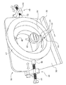
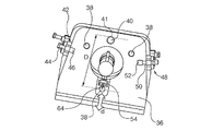
図3〜6を参照すると、半径Rの凸状の内径面形状22を有する公知の減衰コーン20の内径D1は、測定固定具装置30の例示的な実施の形態によって、略リング状のコーンの内径面によって形成された最大凸状突出点23において測定される。固定具30は、ベースプレート32を有しており、ベースプレート32から支持リブ34が突出している。傾斜した測定プレート36は、ベースプレート32と支持リブ34とに溶接ビードおよび/または締結具によって連結されている。3つの受けボタン38が、測定プレート36に連結されており、かつ固定具30内に配置される減衰コーン20の軸方向端面が当接するための基準平面を互いに形成している。位置決めピン40が、測定プレート36の上端に連結されており、かつリング状のコーンの12時の周方向位置において、減衰コーン20の内径面22に対して当接するための接触面41を形成している。傾斜した測定プレート36は、重力を利用して、位置決めピン接触面41をコーンの内径面22に対して強く付勢するように方向付けられている。
Referring to FIGS. 3-6, the inner diameter D 1 of a known damping
固定具30に配置されている減衰コーン20は、コーンの反対側の内径面を12時の周方向位置に鉛直に位置決めおよび位置合わせするために、位置決めピン40を中心に振り子のように揺動される。コーン20が振り子のように揺動する方向は、コーンの直径外面の側面に位置する少なくとも1つの、好ましくは2つのプッシャアセンブリ42,48によって正確に操作される。図3において、左側のプッシャアセンブリ42は、左側のねじ付きねじ44と、コーン20の外面に対して当接する面を有する左側のプッシャ46とを備えている。同様に、右側のプッシャアセンブリ48は、右側のねじ付きねじ50と、コーン20の外面に対して当接する面を有する右側のプッシャ52とを備えている。対向する右側および左側のプッシャアセンブリ42,48を使用することによって得られるさらなる利点は、測定するコーン20を、右側および左側のプッシャ46,52をコーンの外面に対して当接させることによって、測定プレート36に関して固定された揺動位置に固定できることである。
The damping
インジケータホルダ54は、位置決めピン40の反対側において、かつ位置決めピン40に沿って測定プレート36に連結されており、かつ公知の変位インジケータ60の通過および収容のためのスプリットコレットアセンブリ56を受ける。図3および図4に示される例示的な公知の変位インジケータ60は、デジタル表示装置を備えている。例えばアナログ目盛りインジケータまたは変位データを遠隔モニタリング装置に伝送する伝送インジケータなどの代替的な公知のタイプの変位インジケータを、例示的なデジタル表示の変位インジケータ60の代わりとしてもよい。変位インジケータ60は、図5に両矢印dで示される変位軸線を形成している変位可能なスピンドルを備えている。変位軸線dは、位置決めピン40の接触面41と一直線上にある。図5および図6に示される実施の形態において、接触点延長部62が、インジケータ60のスピンドルに装着されており、次いで、刃形変位指針64が接触点延長部に装着されている。
The
図4および図5を参照すると、刃形指針64は、刃形指針64の長い軸線の線状縁部が、減衰コーンの軸方向寸法および位置決めピン40の接触面に平行であるように、減衰コーン20の凸状内径22の面形状に関して方向付けられている。これにより、刃形指針64の線状縁部は、凸状内径面の高点23に対して接線である。このようにして、正確な直線距離Dは、位置決めピン40の接触面41と刃形変位指針64の遠位先端との間で形成される。変位指針の遠位先端部64の変位位置を変位軸線dに沿って変えることによっても、接触面41と変位指針の遠位先端部との間の正確な直線距離Dが変わる。
With reference to FIGS. 4 and 5, the
減衰コーン20の内径D1またはD2は、図3および4の実施の形態の測定固定具30に減衰コーンを配置することによって測定され、それによって、略リング状のコーンの軸方向面が、位置決めピン接触面41および変位指針64の変位先端部が減衰コーン内径面22内に周方向に囲まれて、受けボタン38に置かれる。このようにして、減衰コーンの当接している軸方向端部は、受けボタン38によって形成されている基準面に平行に位置合わせされ、かつ反対位置において向かい合って方向付けられた位置決めピン接触面41および刃形64は、減衰コーンの内径面の両側と(表面が凸状面の場合はそれぞれ高点23と)接触している。この位置において、位置決めピン接触面と刃形64の遠位先端部の線状縁部との間の距離Dは、減衰コーンの内径に対応する。最大直径は、減衰コーン20を、最大直径測定値が得られるまで、プッシャ42,48を用いて位置決めピン40に関して揺動することによって測定することができる。
The inner diameter D 1 or D 2 of the damping
直径の同心性は、減衰コーン20を測定固定具30に関して回転させ、他の周方向位置において対応する直径測定値Dを得ることによって検査することができる。インジケータ60は、インジケータの変位指針64の測定値が指針と位置決めピン接触面41との間の直線距離Dに関連付けられように、固定具30において向きを定めかつ指数付けすることができる。または、インジケータ60は、インジケータ60の変位指針64の変位測定値が所望の基準距離からの変動を示すように、固定具30において向きを定めかつ指数付けすることができる。後者の方法は、有利には、基準ゲージ減衰コーンに関して減衰コーン20を検査する方法を提供する。公知の寸法の減衰コーンゲージは、固定具30に挿入され、かつ内径寸法Dが本明細書に記載されるようにして得られる。インジケータ60によって測定される寸法Dが記録されるか、またはインジケータがその測定寸法において「ゼロ」に指数付けされる。次いで、ゲージ減衰コーンは、他の減衰コーン20の内径D1またはD2が測定できるように測定固定具から取り外される。基準ゲージ減衰コーンから得られたインジケータ60の変位測定値がゼロに設定されている簡易化された内径検査モードにおいて、その後検査される減衰コーン20は、単にインジケータ60の新たな変位測定値が構成部品の公差仕様範囲内にあるかを測定することによって合否を決めることができる。
The concentricity of the diameter can be checked by rotating the damping
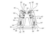
測定固定具装置30’の代替的な実施の形態は図6に示されている。この場合、1対の向かい合う傾斜した測定プレート36,36’が、減衰コーン20の内径D1およびD2が共通する固定具において好都合に測定できるようにベース部32に装着されている。各固定具のそれぞれ対応する構成部品には、例えば、38,38’、40,40’、60,60’のように複数対の共通する参照符合が付されている。
An alternative embodiment of the measurement fixture device 30 'is shown in FIG. In this case, a pair of inclined measured
本発明の教示を含む種々の実施の形態を本明細書において詳細に図示しかつ説明してきたが、当業者は、これらの教示を依然として含む他の多くの様々な実施の形態を容易に考え出すことができる。本発明は、その用途として、詳細な説明に記載されているまたは図面に図示されている構成部品の構成および配置の例示的な実施の形態の詳細に限定されていない。本発明は、別の実施の形態であり得、かつ種々のやり方で実践または実施することができる。また、本明細書において使用される表現および用語は、説明を目的としており、限定するものとして見なされないということが理解される。本明細書において、「含む」、「備える」または「有する」ならびにそれらの変形の使用は、その後に列挙される事項およびその均等物ならびに追加の事項を含むものと理解される。特に規定または限定されていなければ、「取り付けられる」、「接続される」、「支持される」および「連結される」という用語ならびにそれらの変形は、広義に使用され、かつ直接的および間接的な取り付け、接続、支持および連結を含む。さらに、「接続」および「連結」は物理的または機械的な接続または連結には限定されない。 While various embodiments including the teachings of the present invention have been shown and described in detail herein, those skilled in the art will readily devise many other various embodiments that still include these teachings. Can do. The invention is not limited in its application to the details of the exemplary embodiments of the construction and arrangement of the components described in the detailed description or illustrated in the drawings. The invention can be in other embodiments and can be practiced or carried out in various ways. It is also understood that the expressions and terms used herein are for purposes of explanation and are not to be considered limiting. In this specification, the use of “including”, “comprising” or “having” and variations thereof is understood to include the items listed thereafter and equivalents thereof as well as additional items. Unless otherwise specified or limited, the terms “attached”, “connected”, “supported” and “coupled” and variations thereof are used broadly and are both direct and indirect. Installation, connection, support and coupling. Further, “connection” and “coupling” are not limited to physical or mechanical connections or linkages.
10 ガスタービンエンジン
12 タイロッド
14 タービンディスク
15 肩部
16 タービンディスク
17 溝
20 減衰コーン
22 凸状内径面
23 最大凸状突出点
24 リップ
30,30’ 固定具
32 ベースプレート
34 支持リブ
36,36’ 測定プレート
38,38’ 受けボタン
40,40’ 位置決めピン
41,41’ 接触面
42,42’ プッシャアセンブリ
44 左側ねじ
46 左側プッシャ
48 プッシャアセンブリ
50 右側ねじ
52 右側プッシャ
54,54’ インジケータホルダ
56 スプリットコレットアセンブリ
60,60’ 変位インジケータ
62 接触点延長部
64,64’ 刃形指針
D 距離
d 変位軸線
D1 内径
D2 内径
R 半径
DESCRIPTION OF
Claims (17)
基準平面を形成する測定固定具であって、前記形成された基準平面から上方向に突出する、接触面を形成する位置決めピンと、位置決めピン接触面と一直線上にある変位軸線を形成する変位指針を有する、前記測定固定具に連結された変位インジケータとを有する測定固定具を提供することと、
軸方向端面と少なくとも1つの内径面とを有する略リング状のガスタービンエンジン減衰コーンを提供することと、
前記位置決めピン接触面と前記変位指針とを減衰コーン内径面内に周方向に囲み、かつ前記軸方向端面を前記基準平面に対して当接させることと、
インジケータ変位指針の変位位置を前記位置決めピン接触面に関して関連付けることによって減衰コーン内径を測定することと、を含む略リング状のガスタービンエンジン減衰コーンの内径を測定する方法。 A method for measuring an inner diameter of a generally ring-shaped gas turbine engine damping cone comprising an axial end face and at least one inner diameter face comprising:
A measuring fixture for forming a reference plane, comprising: a positioning pin that protrudes upward from the formed reference plane to form a contact surface; and a displacement pointer that forms a displacement axis that is in line with the positioning pin contact surface. Providing a measurement fixture having a displacement indicator coupled to the measurement fixture;
Providing a generally ring-shaped gas turbine engine damping cone having an axial end surface and at least one inner diameter surface;
Surrounding the positioning pin contact surface and the displacement indicator circumferentially within the damping cone inner diameter surface, and abutting the axial end surface against the reference plane;
Measuring the inner diameter of a substantially ring-shaped gas turbine engine damping cone, comprising: measuring a damping cone inner diameter by associating a displacement position of an indicator displacement pointer with respect to the positioning pin contact surface.
前記固定具において前記基準減衰コーンゲージを検査される減衰コーンに置き換え、かつ第2の変位指針変位位置を測定することと、
前記基準変位位置と第2の変位位置とを比較することと、によって減衰コーンの内径を測定する、請求項1記載の方法。 Placing a reference damping cone gauge on the fixture and measuring the reference displacement position of the displacement pointer;
Replacing the reference damping cone gauge with a damping cone to be tested in the fixture and measuring a second displacement pointer displacement position;
The method of claim 1, wherein the inner diameter of the damping cone is measured by comparing the reference displacement position with a second displacement position.
基準変位位置と第2の変位位置とを比較することと、
前記基準変位位置および前記変位位置が許容仕様公差ばらつき内にある場合、前記検査される減衰コーンを内径仕様を満たすものとして指定することと、
前記基準変位位置および前記変位位置が前記許容仕様公差ばらつきの範囲外にある場合、前記内径仕様を満たさないことと、を含む減衰コーンの内径を検査する方法。 A method for inspecting the inner diameter of a damping cone using the method of claim 7, comprising:
Comparing the reference displacement position with the second displacement position;
If the reference displacement position and the displacement position are within tolerance specification tolerance variation, designating the inspected attenuation cone as satisfying an inner diameter specification;
A method for inspecting an inner diameter of a damping cone including: not satisfying the inner diameter specification when the reference displacement position and the displacement position are out of a range of tolerance tolerance variation.
基準平面を形成する測定固定具であって、前記形成された基準平面から上方向に突出する、接触面を形成する位置決めピンと、前記基準平面に直交して方向付けられ、かつ位置決めピン接触面に平行に方向付けられた直線縁部を有する刃形変位指針を有する、前記測定固定具に連結された変位インジケータであって、該変位インジケータは前記位置決めピン接触面と一直線上にある変位軸線を形成している変位インジケータと、を有する測定工程具を提供することと、
前記位置決めピン接触面と前記刃形変位指針とを減衰コーンの内径面内に周方向に囲み、かつ前記軸方向端面を前記基準平面に対して当接させることと、
前記インジケータによって最大内径変位測定値を得るために、前記減衰コーンを前記位置決めピンに関して揺動させ、かつ前記インジケータの刃形部の最大直径変位位置を前記位置決めピン接触面に関して関連付けることによって、前記減衰コーンの内径を測定することと、を含む略リング状のガスタービンエンジン減衰コーンの内径を測定する方法。 A method for measuring the inner diameter of a substantially ring-shaped gas turbine engine damping cone comprising an axial end face and a spherical or another convex inner diameter face shape comprising:
A measuring fixture for forming a reference plane, wherein the positioning pin projects upward from the formed reference plane and forms a contact surface; and is oriented perpendicular to the reference plane and is positioned on the positioning pin contact surface A displacement indicator coupled to the measurement fixture having a blade-shaped displacement pointer having straight edges oriented in parallel, the displacement indicator forming a displacement axis that is in line with the positioning pin contact surface Providing a measurement indicator having a displacement indicator,
Surrounding the positioning pin contact surface and the blade-shaped displacement indicator circumferentially within the inner diameter surface of the damping cone, and bringing the axial end surface into contact with the reference plane;
In order to obtain a maximum bore displacement measurement by the indicator, the damping cone is rocked with respect to the locating pin and the damped portion of the indicator is associated with a maximum diameter displacement position with respect to the locating pin contact surface. Measuring the inner diameter of the cone, and measuring the inner diameter of the substantially ring-shaped gas turbine engine damping cone.
基準平面を形成するベース部と、
前記形成された基準平面から上方向に突出する、接触面を形成する位置決めピンと、
位置決めピン接触面と一直線上にある変位軸線を形成する変位指針を有する、前記ベース部に連結された変位インジケータと、を備え、
前記位置決めピン接触面と前記変位指針とを減衰コーン内径面内に周方向に囲み、前記減衰コーンの前記軸方向端面を前記基準平面に当接させ、かつ前記位置決めピン接触面に関するインジケータ変位指針の変位位置を前記内径に関連付けることによって、前記減衰コーンの内径を測定する、略リング状のガスタービンエンジン減衰コーンの内径を測定する装置。 An apparatus for measuring an inner diameter of a generally ring-shaped gas turbine engine damping cone having an axial end face and at least one inner diameter,
A base portion forming a reference plane;
A positioning pin that protrudes upward from the formed reference plane to form a contact surface;
A displacement indicator coupled to the base portion having a displacement indicator that forms a displacement axis that is in line with the positioning pin contact surface;
The positioning pin contact surface and the displacement pointer are circumferentially enclosed within the inner surface of the damping cone, the axial end surface of the damping cone is brought into contact with the reference plane, and an indicator displacement pointer for the positioning pin contact surface An apparatus for measuring an inner diameter of a substantially ring-shaped gas turbine engine damping cone that measures an inner diameter of the damping cone by associating a displacement position with the inner diameter.
減衰コーンの軸方向端面に対して当接するための、前記測定プレートに連結された、前記基準平面を形成している3つの基準ボタンと、をさらに備える請求項11記載の装置。 A measuring plate connected to the base at an inclined angle;
12. The apparatus of claim 11, further comprising three reference buttons forming the reference plane connected to the measurement plate for abutting against an axial end face of the attenuation cone.
減衰コーンの軸方向端面に対して当接するための、測定プレートそれぞれに連結された3つの基準ボタンであって、基準ボタンは第1の基準平面および第2の基準平面をそれぞれ形成している3つの基準ボタンと、
前記第1の基準平面および前記第2の基準平面それぞれから上方向に突出した、それぞれ接触面を形成している第1の位置決めピンおよび第2の位置決めピンと、
前記第1の測定プレートおよび前記第2の測定プレートそれぞれに連結された第1の変位インジケータおよび第2の変位インジケータであって、各インジケータは、各位置決めピン接触面と一直線上にある変位軸線を形成している変位指針を有する、第1の変位インジケータおよび第2の変位インジケータとをさらに備える、請求項11記載の装置。 A first measurement plate and a second measurement plate connected to the base portion at an inclined angle;
Three reference buttons connected to each of the measurement plates for abutting against the axial end face of the attenuation cone, the reference buttons forming a first reference plane and a second reference plane, respectively 3 One reference button,
A first positioning pin and a second positioning pin, each projecting upward from each of the first reference plane and the second reference plane, each forming a contact surface;
A first displacement indicator and a second displacement indicator coupled to the first measurement plate and the second measurement plate, respectively, each indicator having a displacement axis which is in line with each positioning pin contact surface; The apparatus of claim 11, further comprising a first displacement indicator and a second displacement indicator having a forming displacement pointer.
Applications Claiming Priority (2)
| Application Number | Priority Date | Filing Date | Title |
|---|---|---|---|
| US14/105,251 US9316493B2 (en) | 2013-12-13 | 2013-12-13 | Method and apparatus for determining gas turbine dampening cone inner diameter |
| US14/105,251 | 2013-12-13 |
Publications (1)
| Publication Number | Publication Date |
|---|---|
| JP2015114333A true JP2015114333A (en) | 2015-06-22 |
Family
ID=52100994
Family Applications (1)
| Application Number | Title | Priority Date | Filing Date |
|---|---|---|---|
| JP2014252368A Pending JP2015114333A (en) | 2013-12-13 | 2014-12-12 | Method and device for determining gas turbine dampening cone inner diameter |
Country Status (5)
| Country | Link |
|---|---|
| US (1) | US9316493B2 (en) |
| EP (1) | EP2884058A1 (en) |
| JP (1) | JP2015114333A (en) |
| KR (1) | KR20150069561A (en) |
| CN (1) | CN104713451A (en) |
Cited By (1)
| Publication number | Priority date | Publication date | Assignee | Title |
|---|---|---|---|---|
| WO2020036120A1 (en) * | 2018-08-17 | 2020-02-20 | 三菱日立パワーシステムズ株式会社 | Position adjustment method and position adjustment jig for arc-shaped member |
Families Citing this family (5)
| Publication number | Priority date | Publication date | Assignee | Title |
|---|---|---|---|---|
| FR2985306B1 (en) * | 2011-12-29 | 2018-06-15 | Vallourec Oil And Gas France | DEVICE FOR MEASURING AN INTERNAL OR EXTERNAL PROFILE OF A TUBULAR COMPONENT |
| IT201600123382A1 (en) * | 2016-12-05 | 2018-06-05 | Ansaldo Energia Spa | METHOD AND DEVICE FOR CHECKING THE POSITIONING OF AT LEAST ONE ROTOR DISC AROUND A ROTOR TIE ROD OF A GAS TURBINE |
| CN111536876B (en) * | 2020-06-02 | 2021-07-13 | 华东理工大学 | A method for in-situ measurement of sealing surface of triple eccentric butterfly valve |
| JP7853133B2 (en) * | 2022-03-24 | 2026-04-28 | 株式会社ミツトヨ | Control method for an automatic internal diameter measuring device, and control method for an automatic measuring device |
| CN117066971B (en) * | 2023-08-14 | 2025-11-18 | 沈阳富创精密设备股份有限公司 | A measuring device for continuously detecting the diameter of a workpiece being machined on a two-axis CNC machine tool. |
Family Cites Families (14)
| Publication number | Priority date | Publication date | Assignee | Title |
|---|---|---|---|---|
| US1403156A (en) * | 1920-07-06 | 1922-01-10 | Gonzalez Ramon | Boiler-diagramming apparatus |
| GB1589297A (en) * | 1976-12-24 | 1981-05-13 | Rolls Royce | Probe for use in measuring apparatus |
| US4521968A (en) * | 1982-10-12 | 1985-06-11 | Westinghouse Electric Corp. | Mapping system for an internal cylindrical surface |
| US4520568A (en) | 1984-03-27 | 1985-06-04 | 4D Incorporated | Brake drum gauge |
| US4821425A (en) * | 1987-11-18 | 1989-04-18 | United States Of America As Represented By The Administrator, National Aeronautics And Space Administration | Cylindrical surface profile and diameter measuring tool and method |
| US5377421A (en) * | 1993-04-30 | 1995-01-03 | Isler; David | Centering tool for cylinder gauge |
| US5711083A (en) * | 1995-09-11 | 1998-01-27 | Bidwell Corporation | Gage set for measuring inside and outside diameters of ring-shaped parts |
| US6381861B1 (en) * | 1999-08-20 | 2002-05-07 | Gary W. Deterling | Effective diameter system |
| EP1150092A3 (en) * | 2000-04-12 | 2001-11-07 | Bidwell Corporation | Gage set for measuring ring shaped parts |
| US6868618B2 (en) * | 2001-10-01 | 2005-03-22 | Marcello Navarro | Gauge and method |
| US6931751B2 (en) * | 2002-08-28 | 2005-08-23 | General Electric Company | Methods and apparatus for securing components for inspection |
| US6996914B1 (en) * | 2004-08-09 | 2006-02-14 | Project Consulting Services, Inc. | Method and apparatus for best fitting two or more items |
| DE102008060621B3 (en) * | 2008-12-05 | 2010-08-12 | Carl Zeiss Ag | Optical arrangement for the contactless measurement or testing of a body surface |
| EP2492452A1 (en) * | 2011-02-22 | 2012-08-29 | Siemens Aktiengesellschaft | Method for constructing a turbo machine |
-
2013
- 2013-12-13 US US14/105,251 patent/US9316493B2/en active Active
-
2014
- 2014-11-24 EP EP14194502.2A patent/EP2884058A1/en not_active Withdrawn
- 2014-12-12 CN CN201410759813.9A patent/CN104713451A/en active Pending
- 2014-12-12 JP JP2014252368A patent/JP2015114333A/en active Pending
- 2014-12-15 KR KR1020140180337A patent/KR20150069561A/en not_active Withdrawn
Cited By (4)
| Publication number | Priority date | Publication date | Assignee | Title |
|---|---|---|---|---|
| WO2020036120A1 (en) * | 2018-08-17 | 2020-02-20 | 三菱日立パワーシステムズ株式会社 | Position adjustment method and position adjustment jig for arc-shaped member |
| JPWO2020036120A1 (en) * | 2018-08-17 | 2021-08-10 | 三菱パワー株式会社 | Position adjustment method and position adjustment jig for arc-shaped members |
| JP7105892B2 (en) | 2018-08-17 | 2022-07-25 | 三菱重工業株式会社 | Arc-shaped member position adjustment method and position adjustment jig |
| US11668208B2 (en) | 2018-08-17 | 2023-06-06 | Mitsubishi Heavy Industries, Ltd. | Positioning method of arc-like member and positioning jig |
Also Published As
| Publication number | Publication date |
|---|---|
| KR20150069561A (en) | 2015-06-23 |
| US20150168139A1 (en) | 2015-06-18 |
| US9316493B2 (en) | 2016-04-19 |
| EP2884058A1 (en) | 2015-06-17 |
| CN104713451A (en) | 2015-06-17 |
Similar Documents
| Publication | Publication Date | Title |
|---|---|---|
| CN1991293B (en) | Fixing assembly and testing method for ring seals | |
| US9316493B2 (en) | Method and apparatus for determining gas turbine dampening cone inner diameter | |
| CN102679941A (en) | Device for detecting taper of outer cone of conical ring | |
| CN103822565B (en) | A kind of pitch-row comparing measuring apparatus | |
| CN110207568A (en) | For detecting the detection device and method of the position precision of connecting rod side and cage face | |
| WO2022146326A1 (en) | Perpendicularity measuring device for the inner diameter of bearing rings | |
| CN105928435A (en) | Bouncing detector for end-surface counter bore of bevel gear | |
| CN204165479U (en) | Deep hole diameter run-out cubing in axle | |
| US20200271537A1 (en) | Second harmonic runout simulation hub | |
| JP2011521219A (en) | Probe for checking the surface of the circumferential recess of a turbojet engine disk using Foucault current | |
| US11320332B2 (en) | First harmonic runout simulation hub | |
| CN211824165U (en) | A tool for measuring the length on a nominal circle of a conical surface | |
| WO2021031504A1 (en) | Measurement device for crankshaft taper length | |
| CN204479004U (en) | Capstan rotor concentricity proving installation | |
| CN209131563U (en) | A kind of tape spool outside diameter measuring tooling | |
| CN205718727U (en) | Motor housing bearing chamber is beated value detection device | |
| CN212253911U (en) | Axial dimension measuring tool | |
| CN102901423B (en) | Valve seat ring jerk testing tool | |
| CN114754656A (en) | Taper detector for taper hole | |
| CN116007470A (en) | Measuring device and measuring method | |
| CN103376046A (en) | Handheld measuring instrument for internal spline M value | |
| CN210981095U (en) | Online wall thickness detection tool for special-shaped ring part | |
| CN202032986U (en) | Inner spherical surface diameter testing fixture | |
| JP2009257887A (en) | Inner peripheral surface measuring apparatus | |
| CN115325908B (en) | Measuring tool and method for testing the distance from the cross section to the end face at the inner cone surface of an annular part |