JP2015114245A - Clamp sensor and measuring device - Google Patents
Clamp sensor and measuring device Download PDFInfo
- Publication number
- JP2015114245A JP2015114245A JP2013257418A JP2013257418A JP2015114245A JP 2015114245 A JP2015114245 A JP 2015114245A JP 2013257418 A JP2013257418 A JP 2013257418A JP 2013257418 A JP2013257418 A JP 2013257418A JP 2015114245 A JP2015114245 A JP 2015114245A
- Authority
- JP
- Japan
- Prior art keywords
- arm body
- clamp
- clamp sensor
- pair
- current detection
- Prior art date
- Legal status (The legal status is an assumption and is not a legal conclusion. Google has not performed a legal analysis and makes no representation as to the accuracy of the status listed.)
- Pending
Links
Images
Landscapes
- Measuring Instrument Details And Bridges, And Automatic Balancing Devices (AREA)
Abstract
Description
本発明は、電流の測定の際に用いられるクランプセンサおよび測定装置に関する。 The present invention relates to a clamp sensor and a measuring apparatus used for measuring current.
電線を挟み込んで、その電線に流れる電流を測定するクランプ式の電流センサ(クランプセンサ)が広く用いられている。かかるクランプセンサは、コアを収納する一対のアーム体を備え、そのアーム体が開閉することで、電線を保持するクランプ空間を開放したり閉じたりすることができる。 A clamp-type current sensor (clamp sensor) that sandwiches an electric wire and measures a current flowing through the electric wire is widely used. Such a clamp sensor includes a pair of arm bodies that house cores, and the arm bodies can be opened and closed to open and close a clamp space that holds an electric wire.
このようなクランプセンサには、特許文献1に示すように、スライド式のものがある。特許文献1に開示のスライド式のクランプセンサでは、ノブを介して、上側のアーム体をスライドさせることで、クランプ空間を開閉可能となっている。また、クランプセンサには、特許文献2に開示するように、スライド式とは異なる回動式のものがある。回動式のクランプセンサでは、上側のアーム体と下側のアーム体とが、回動軸を支点として、互いに接離することで、クランプ空間を開閉可能となっている。 As such a clamp sensor, as shown in Patent Document 1, there is a slide type sensor. In the slide-type clamp sensor disclosed in Patent Document 1, the clamp space can be opened and closed by sliding the upper arm body through a knob. In addition, as disclosed in Japanese Patent Application Laid-Open No. 2004-228620, there is a clamp sensor that is different from a slide sensor. In the rotating clamp sensor, the upper arm body and the lower arm body are brought into and out of contact with each other with the rotating shaft as a fulcrum, so that the clamp space can be opened and closed.
ところで、特許文献1に開示のクランプセンサは、上側のアーム体が下側のアーム体に対してスライドする方式を採用している。かかる特許文献1に開示のクランプセンサでは、上側のアーム体のスライド量は、そのスライド方向におけるクランプ空間の距離と、そのクランプ空間よりもアーム体の先端側に位置する部位の寸法との合算分を、少なくともスライドさせる必要がある。それにより、電線の直径が大きくなると、上側のアーム体のスライド量が多くなってしまう。 Incidentally, the clamp sensor disclosed in Patent Document 1 employs a method in which the upper arm body slides with respect to the lower arm body. In the clamp sensor disclosed in Patent Document 1, the slide amount of the upper arm body is the sum of the distance of the clamp space in the slide direction and the dimension of the portion located on the tip side of the arm body from the clamp space. Need to slide at least. Thereby, when the diameter of an electric wire becomes large, the sliding amount of an upper arm body will increase.
そのため、片手でクランプセンサを把持しながら、たとえば親指等の指でノブをスライドさせてクランプ空間の開閉を行おうとしても、十分な力を発揮できる状態での指の可動範囲には限りがあるので、開閉の際の操作性が悪くなる虞がある。 Therefore, even when the clamp sensor is held with one hand and the knob is slid with a finger such as a thumb to open and close the clamp space, the movable range of the finger in a state where sufficient force can be exerted is limited. Therefore, the operability during opening and closing may be deteriorated.
また、特許文献2に開示のクランプセンサにおいては、たとえば当該特許文献2の図1等から明らかなように、クランプセンサの長手方向の一端側に回動軸が位置し、他端側にアーム体の先端側が位置している。そのため、アーム体を開閉させる際には、クランプ空間側が回動軸から遠くなり、回動量が多くなる。したがって、片手でクランプセンサを把持しながら、アーム体の開閉を行おうとしても、開閉の際の操作性が悪くなる虞がある。 Further, in the clamp sensor disclosed in Patent Document 2, for example, as is clear from FIG. 1 of Patent Document 2, the rotation shaft is located on one end side in the longitudinal direction of the clamp sensor, and the arm body is located on the other end side. The tip side of is located. Therefore, when opening and closing the arm body, the clamp space side is far from the rotation axis, and the rotation amount is increased. Therefore, even if the arm body is opened and closed while holding the clamp sensor with one hand, the operability during opening and closing may be deteriorated.
本発明は上記の事情にもとづきなされたもので、その目的とするところは、片手で把持しながらもクランプ空間の開閉に際しての操作性を良好にすることが可能なクランプセンサおよび測定装置を提供しよう、とするものである。 The present invention has been made based on the above circumstances, and an object of the present invention is to provide a clamp sensor and a measuring device that can improve the operability when opening and closing the clamp space while holding it with one hand. .
上記課題を解決するために、本発明の第1の観点によると、電流を導通させる電線に流れる電流を測定するクランプセンサであって、電流検出部を収納すると共に、一方が他方に対してスライドすることにより電線が位置するクランプ空間の周囲を電流検出部が閉ループ状に覆う閉じ状態とクランプ空間が開放された開き状態とを実現し、かつ閉じ状態では電流検出部が電線の周囲を覆う状態で突き合わされる一対のアーム体と、アーム体の先端側を突出させると共に後端側を収納する筐体と、筐体に設けられると共に、一対のアーム体を互いに逆方向に移動させる逆方向移動機構と、を具備することを特徴とするクランプセンサが提供される。 In order to solve the above-described problem, according to a first aspect of the present invention, a clamp sensor for measuring a current flowing in an electric wire that conducts current, which houses a current detection unit and one slides with respect to the other. To realize a closed state in which the current detection unit covers the periphery of the clamp space where the electric wire is located in a closed loop and an open state in which the clamp space is opened, and the current detection unit covers the periphery of the electric wire in the closed state A pair of arm bodies abutted on each other, a housing that projects the front end side of the arm body and houses the rear end side, and a reverse movement that is provided on the housing and moves the pair of arm bodies in opposite directions to each other And a clamp sensor characterized by comprising a mechanism.
また、本発明の他の側面は、上述の発明において、逆方向移動機構は、支軸を有し、この支軸を介して回動可能に設けられていると共に、支軸よりも一端寄りと他端寄りにそれぞれ長尺状の長孔部を有するリンク部材と、アーム体に固定的に設けられていると共に長孔部に挿入されてこの長孔部を摺動する摺動ピンと、を具備することが好ましい。 Further, according to another aspect of the present invention, in the above-described invention, the reverse direction moving mechanism has a support shaft, is provided so as to be rotatable through the support shaft, and is closer to one end than the support shaft. A link member having an elongated slot portion near the other end, and a slide pin that is fixedly provided on the arm body and is inserted into the slot portion and slides in the slot portion. It is preferable to do.
さらに、本発明の他の側面は、上述の発明において、逆方向移動機構は、一対のアーム体の一方側と他方側とで向きの異なる駆動力を与える中心ギヤ部と、それぞれのアーム体に設けられると共に、中心ギヤ部により与えられる駆動力を受け止める係合部と、を具備することが好ましい。 Further, according to another aspect of the present invention, in the above-described invention, the reverse movement mechanism includes a central gear portion that applies driving forces having different directions on one side and the other side of the pair of arm bodies, and each arm body. And an engaging portion that receives the driving force applied by the central gear portion.
また、本発明の他の側面は、上述の発明において、アーム体の移動を規制して、当該アーム体の閉じ状態と開き状態のうちの少なくとも一方を維持するロック機構が設けられている、ことが好ましい。 According to another aspect of the present invention, in the above-described invention, a lock mechanism that restricts movement of the arm body and maintains at least one of a closed state and an open state of the arm body is provided. Is preferred.
また、本発明の他の側面は、測定装置に関するものであり、この測定装置は、上述の各発明に係るクランプセンサを備える、ことが好ましい。 In addition, another aspect of the present invention relates to a measuring apparatus, and the measuring apparatus preferably includes the clamp sensor according to each of the above-described inventions.
本発明によると、片手で把持しながらもクランプ空間の開閉に際しての操作性を良好にすることが可能なクランプセンサおよび測定装置を提供することができる。 According to the present invention, it is possible to provide a clamp sensor and a measurement apparatus that can improve the operability when opening and closing the clamp space while holding it with one hand.
以下、本発明の一実施の形態に係るクランプセンサ10および測定装置100について、図面に基づいて説明する。なお、以下の説明においては、XYZ直交座標系を用いて説明する場合があるものとし、X方向をクランプセンサ10の長手方向とし、X1側は図1において奥側かつ右側、X2側は図1において手前側かつ左側とする。またZ方向をクランプセンサ10の上下方向とし、Z1側は上側、Z2側は下側とする。またY方向はX方向およびY方向に直交する方向とし、Y1側は図1において手前側かつ右側、Y2側はそれとは逆の奥側かつ左側とする。
Hereinafter, a
本発明は、クランプセンサ10において、一対のアーム体30を互いに逆方向に移動する構成(逆方向移動機構)を採用することで、それぞれのアーム体30における移動量が少なくなるように抑えることを要旨とするものである。以下、その詳細について、説明する。
The present invention employs a configuration (reverse direction moving mechanism) that moves the pair of
<クランプセンサ10の概略構成について>
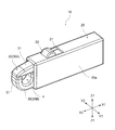
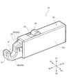
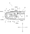
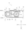
図1は、クランプセンサ10の構成を示す斜視図であり、アーム体30が閉じ状態にあるときを示す図である。図2は、同じくクランプセンサ10の構成を示す斜視図であり、アーム体30が開き状態にあるときを示す図である。また、図3は、アーム体30が閉じているときの構成を示す部分的な側断面図である。
<About the schematic configuration of the
FIG. 1 is a perspective view showing the configuration of the
本実施の形態におけるクランプセンサ10は、クランプ式の電流センサであり、電線をクランプ空間Pに配置可能としている。なお、本実施の形態のクランプセンサ10は、交流および直流のいずれでも測定可能であるが、交流と直流のいずれかのみを測定可能としても良い。このクランプセンサ10は、筐体20を備えると共に、筐体20に対してスライド自在な一対のアーム体30を備えている。アーム体30の一方側(X2側;先端側)は、筐体20から飛び出していて、その飛び出し部分にて電線を挟み込んで、その電線に流れる電流を測定可能としている。
The
なお、アーム体30の他方側(X1側;後端側)は、筐体20に収納されている。
The other side (X1 side; rear end side) of the
アーム体30は、スライドケース31と、電流検出部32とを備えている。スライドケース31には、図3に示すような電流検出部32が収納されている。そのため、図1に示すようなアーム体30の閉じ状態では、一対の電流検出部32が突き合わされて、閉じた磁気回路が構成される。以下の説明では、必要に応じて、上側のアーム体30を、上側アーム体30Aとし、下側のアーム体30を、下側アーム体30Bと称呼する。なお、電流検出部32としては、磁気コアやソレノイドが挙げられるが、それ以外の構成であっても良い。
The
ここで、図1に示すように、上側アーム体30Aのうち筐体20から突出している部分は、その一端側(X2側)に向かうにつれて、徐々に高さ方向の寸法が小さくなるように設けられている。また、下側アーム体30Bのうち筐体20から突出している部分は、その一端側(X2側)に向かうにつれて、徐々に上側(Z1側)に向かって湾曲している。このような構成とすることにより、アーム体30の一端側(X2側)の高さ寸法が小さくなるので、一対のアーム体30を、狭いスペースに差し込み易くなり、狭い場所であっても電線を良好にクランプすることができる。
Here, as shown in FIG. 1, the portion of the
上側アーム体30Aには、ノブ33が設けられている。図1〜図3に示す構成例では、上側のスライドケース31の上面側のうち、筐体20に収納されている一部分を上方に突出させて、ノブ33が形成されている。ただし、ノブ33は、上側のスライドケース31とは別体的に設けられていても良い。また、筐体20の上面側には、当該筐体20の上面側を切り欠いた切欠部21が設けられていて、この切欠部21を介して、ノブ33が筐体20よりも上方側に突出している。この切欠部21は、ノブ33のスライドを許容する部分でもあり、そのため切欠部21は、長孔形状に設けられている。なお、かかる切欠部21の長さは、アーム体30の閉じ状態と開き状態を少なくとも阻害しない程度に設けられている。ただし、切欠部21は、それ以上の長さに設けられていても良い。
A
それぞれのアーム体30は、筐体20の図示を省略するガイド機構によって、X方向に沿うスライドがガイドされる。このようなガイド機構としては、筐体20とアーム体30のうちのいずれか一方側に突起部分を形成し、いずれか他方側に長溝部分を形成して、突起部分が長溝部分によってガイドされるものがある。ただし、それ以外のガイド機構としても良い。
Each
一対のアーム体30は、図1に示すような閉じ状態では、閉じたクランプ空間Pを形成する。ここで、クランプ空間Pとは、図1に示すような上側アーム体30Aと下側アーム体30Bとの突き合せ状態(一対の電流検出部32の突き合せ状態)で、それらに囲まれた空間部分を指し、この部分に測定対象である電線が位置する。なお、クランプ空間Pは、下側アーム体30Bの上方に上側アーム体30Aが位置することによって形成されるが、図2に示すようなアーム体30の開き状態のときには、クランプ空間Pが開放状態にある、としても良い。
The pair of
また、一対のアーム体30は、付勢バネ40によって付勢されているが、その付勢の向きは、一対のアーム体30が閉じる向きとなっている。そのため、ユーザがクランプセンサ10から手を離すと、一対のアーム体30が自動的に閉じるようになっている。そのような付勢力を与えるため、図3に示す構成例では、上側アーム体30Aには突起状のバネ受部34が設けられていて、このバネ受部34がコイルスプリング状の付勢バネ40の内周側に入り込んで、付勢バネ40の他端側を受け止める。図示は省略しているが、付勢バネ40の一端側も、バネ受部34と同様の構成によって受け止められている。
In addition, the pair of
なお、付勢バネ40を支持する構成は、かかる構成には限られない。たとえば凹部を形成して、その凹部に付勢バネ40の少なくとも一方の端部を挿入することで、付勢バネ40が支持される構成としても良い。また、付勢バネ40を引っ張りバネとして、ユーザがクランプセンサ10から手を離した場合に、自動的にクランプ空間Pが開くような付勢力を与えても良い。
In addition, the structure which supports the urging | biasing
また、一対のアーム体30の開き状態と閉じ状態のうちの少なくとも一方を維持するために、ロック機構を設けるようにしても良い。ロック機構を設ける場合、たとえば長手がX方向に沿う板バネの一部に凸状の部位を設け、またスライドケース31のうち板バネに対向する部位にも突出部を設け、板バネを撓み変形させて閉じ状態が実現されると共に、同じく板バネを撓み変形させない限りは、閉じ状態または開き状態が維持される構成とするものがある。また、バネの押圧によりフック状の部分やピン状の部分が係止部位に係止されて、閉じ状態または開き状態を維持する構成を採用しても良い。
Further, a lock mechanism may be provided to maintain at least one of the opened state and the closed state of the pair of
ここで、一対のアーム体30は、筐体20の内部側では、互いに密接せずに離れていて、その離れた隙間の部分に、後述する支軸52が位置している。ただし、アーム体30の前方側(X2側)では、下側アーム体30Bは、上方側に突出していて、アーム体30の閉じ状態では互いに接触する。
Here, the pair of
また、一対のアーム体30の間には、リンク機構50が設けられている。リンク機構50は、一対のアーム体30がスライドする際に、互いに逆向きにスライドするのを実現するための機構であり、逆方向移動機構に対応する。このリンク機構50は、リンク部材51と、摺動ピン54とを有している。
A
リンク部材51は、図3に示すように、長尺状部材であり、その側面のうち長手方向の中央側には、支軸52が設けられている。支軸52の端部側は、筐体20の内壁に存在する支持凹部(図示省略)に入り込み、それによってリンク部材51が筐体20の内壁により回動自在に支持されるが、それ以外の支持形態としても良い。なお、支軸52は、リンク部材51と一体的に設けられていても良く、リンク部材51とは別体的に設けられていても良い。
As shown in FIG. 3, the
また、リンク部材51には、長孔部53が設けられている。長孔部53は、図3に示すように、リンク部材51の長手方向に長い孔部分である。なお、長孔部53は、貫通していない凹部であっても良い。図3に示すように、それぞれの長孔部53には、摺動ピン54が入り込む。摺動ピン54は、それぞれのスライドケース31の側壁31aから突出しているが、この摺動ピン54はスライドケース31に対して固定的に設けられている。なお、摺動ピン54は、側壁31aに対して別体的に設けられていても良く、一体的に設けられていても良い。
The
以下の説明では、必要に応じて、上側アーム体30Aのスライドケース31から突出する摺動ピン54を摺動ピン54aと称呼し、下側アーム体30Bのスライドケース31から突出する摺動ピン54を摺動ピン54bと称呼するものとする。また、摺動ピン54が入り込む長孔部53を長孔部53aと称呼し、下側アーム体30Bのスライドケース31から突出する摺動ピン54が入り込む長孔部53を長孔部53bと称呼するものとする。
In the following description, the sliding
ここで、摺動ピン54は、アーム体30の閉じ状態と開き状態との間において、長孔部53の端部につっかえることがなく、それらの間で良好に長孔部53を摺動可能となっている。
Here, the sliding
また、アーム体30には、移動規制部35が設けられている。移動規制部35は、開き状態から閉じ状態に移行したアーム体30が、さらに同じ向き(閉じ状態と同じ向き;上側アーム体30AがX1側に向かう向き)に移動してしまうのを防ぐための部分である。図3に示す構成では、上方側のスライドケース31には、後方側凸部35aが下方に向かい突出するように設けられている。一方、下方側のスライドケース31には、後方側凸部35aよりも前方側(X2側)で上方に突出する上方突出部35bが設けられている。そして、後方側凸部35aの前端面(X2側の面)と、上方突出部35bの後端面(X1側の面)とが当接することにより、アーム体30がさらに閉じる向きに移動するのを防止可能となる。
The
<動作について>
以上のような構成を有するクランプセンサ10を用いる場合、ユーザは、筐体20を把持した状態で、付勢バネ40の付勢力に抗しながらノブ33を押し込む。この押し込みの向きは、図1〜図3における他方側(X1側)となっている。すると、閉じ状態となっているアーム体30は、開く向きに移動する。具体的には、上側アーム体30Aは、他方側(X1側)に向かって移動する。すると、摺動ピン54も、上側アーム体30Aと共に他方側(X1側)に向かい移動する。
<About operation>
When the
ここで、上側の摺動ピン54aは長孔部53aに入り込んでいるので、摺動ピン54aの移動に伴って、リンク部材51は、図3において時計回りに回動させられる。すると、長孔部53b側では、リンク部材51は一方側(X2側)に向かい回動する。それにより、長孔部53bに入り込んでいる下側の摺動ピン54bは、長孔部53bの壁面によって一方側(X2側)に向かい押し込まれ、それによって下側アーム体30Bが一方側(X2側)に押し込まれる。
Here, since the
このように、図1に示す状態から、上側アーム体30Aが他方側(X1側)にスライドすると共に、下側アーム体30Bが一方側(X2側)にスライドすることで、クランプ空間Pの閉じ状態が開放された、図2に示すような開き状態が実現される。かかる開き状態では、クランプ空間Pが閉じておらずに開放されているので、このクランプ空間Pに電流を導通させる電線を位置させることができる。
As described above, the
ここで、上述の特許文献1に開示の構成では、上側のアーム体のみがスライドする構成のため、上側のアーム体のスライド量が多くなっている。しかし、上述のように、上側アーム体30Aと下側アーム体30Bとがそれぞれ逆向きにスライドすることにより、それぞれのアーム体30のスライド量は、特許文献1に開示の構成より大幅に少なくなる。たとえば、アーム体30のスライド量を、特許文献1に開示の構成と比較して半分程度となっている。
Here, in the configuration disclosed in Patent Document 1 described above, since only the upper arm body slides, the sliding amount of the upper arm body is large. However, as described above, when the
そして、電線をクランプ空間Pに位置させた後に、ノブ33から手を離すと、付勢バネ40の付勢力により、上記とは逆向きに移動する。すなわち、図2に示すような開き状態となっているアーム体30は、閉じる向きに移動し、最終的には図1に示すような閉じ状態となる。このとき、一対の電流検出部32が電線の周囲をループ状に覆う状態となる。また、かかる閉じ状態とすることで、電線を流れる電流を測定することが可能となる。
Then, after the electric wire is positioned in the clamp space P, when the hand is released from the
<逆方向移動機構の別の構成例について>
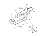
次に、上述したリンク機構50とは異なる、逆方向移動機構の別の構成例とは別の構成例について説明する。図5は、逆方向移動機構としての、ギヤ機構60の概略的な構成を示す側面図である。この図5に示すように、一対のアーム体30の間には、ギヤ機構60が設けられている。ギヤ機構60は、ラックアンドピニオンを有していて、ラックギヤ61がそれぞれのアーム体30に設けられていると共に、ピニオンギヤ62が筐体20に対して回転可能に支持されている。なお、ピニオンギヤ62は中心ギヤ部に対応し、ラックギヤ61は係合部に対応する。
<About another configuration example of the reverse movement mechanism>
Next, a configuration example different from the above-described
すなわち、それぞれのスライドケース31には、ラックギヤ61が設けられている。かかるラックギヤ61は、スライドケース31に対して一体成型されていても良いが、ラックギヤ61をスライドケース31とは別体的に形成した後に、スライドケース31にラックギヤ61を固定しても良い。また、ラックギヤ61は、スライドケース31を構成する一対の側壁31aの間に位置する構成とするのが好ましい。
That is, each
また、ピニオンギヤ62は、回転軸63を支点として、回転自在に設けられている。回転軸63は、筐体20の一対の側壁20aに設けられている凹部(図示省略)に位置し、その凹部により軸支されている。ただし、回転軸63は、筐体20に取り付けられる軸受部材を介して軸支される構成を採用しても良い。なお、回転軸63は、ピニオンギヤ62と一体的に設けられていても良いが、別体的に設けられていても良い。
The
なお、ギヤ機構60を用いる構成においても、上述のような付勢バネ40や、ロック機構を設けることは、勿論可能である。
Even in the configuration using the gear mechanism 60, it is of course possible to provide the urging
<動作について>
以上のようなギヤ機構60を有する構成の場合、ユーザは、筐体20を把持した状態で、付勢バネ40の付勢力に抗しながら、図1、図3における他方側(X1側)に向けてノブ33を押し込む。すると、閉じ状態となっているアーム体30は、開く向きに移動するが、このとき、上側アーム体30Aは、他方側(X1側)に向かって移動する。
<About operation>
In the case of the configuration having the gear mechanism 60 as described above, the user holds the
すると、上側アーム体30Aに設けられているラックギヤ61の他方側(X1側)に向かう移動により、ピニオンギヤ62は時計回りに回転させられる。このピニオンギヤ62は、下側アーム体30Bのラックギヤ61とも噛み合っているので、下側アーム体30Bは、ピニオンギヤ62の回転に伴って一方側(X2側)に向かい移動させられる。
Then, the
それにより、図1に示すクランプ空間Pの閉じ状態から、図2に示すようなクランプ空間Pの開き状態が実現され、このクランプ空間Pに電流を導通させる電線を位置させることができる。 Thereby, the open state of the clamp space P as shown in FIG. 2 is realized from the closed state of the clamp space P shown in FIG. 1, and an electric wire that conducts current can be positioned in the clamp space P.
<測定装置100の概略構成について>
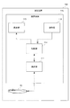
上述したクランプセンサ10は、測定装置100を構成する構成要素とすることができる。その例を、図6に示す。図6は、クランプセンサ10を有する測定装置100の概略的な構成を示す図である。
<About a schematic structure of the measuring
The
図6に示す測定装置100は、たとえば、検出対象体としての電線に流れる電流等のような電気的パラメータを測定可能に構成されている。この測定装置100は、上述したクランプセンサ10の他に、装置本体110を備えている。
A measuring
図6に示すように、装置本体110は、測定部111、操作部112、表示部113および制御部114を備えている。測定部111は、制御部114の制御に従って、クランプセンサ10によって測定された電流に基づいて電線に流れる電流を測定する測定処理を実行する。
As shown in FIG. 6, the apparatus
操作部112は、各種のスイッチを備えて構成され、各スイッチが操作されたときに操作信号を出力する。表示部113は、制御部114の制御に従って電流の測定値等を表示する。制御部114は、操作部112から出力される操作信号に従って装置本体110を構成する各部を制御する。さらに、制御部114には、測定部111での測定処理の結果が測定部111から入力される。なお、測定装置100においては、電流以外に、直流電圧、交流電圧、直流電圧と交流電圧の同時測定、直流電流、交流電流、直流電流と交流電流の同時測定、抵抗、コンダクタンス、静電容量、周波数、ダイオード測定、測定レンジの変更、電気的導通の検出、温度等を始めとする種々のものを測定可能としても良い。
The
<効果について>
以上のような構成のクランプセンサ10および測定装置100によると、たとえばリンク機構50やギヤ機構60といった逆方向移動機構を備えることにより、一対のアーム体30を、互いに逆向きにスライドさせることにより、それぞれのアーム体30のスライド量は、特許文献1に開示の構成より大幅に少なくすることができる。たとえば、上側アーム体30Aのスライド量を、特許文献1の構成と比較して半分程度に低減することが可能となる。
<About effect>
According to the
それにより、片手で構成のクランプセンサ10を把持しながらでも、ノブ33を押し込んで上側アーム体30Aを容易にスライドさせることが可能となる。そのため、クランプセンサ10の開閉動作における操作性を良好にすることが可能となる。また、上側アーム体30Aのスライド量が、たとえば半分程度といった具合に低減されるので、片手での操作でありながらも、直径の大きな電線を測定対象とすることが可能となる。
Accordingly, the
また、特許文献2の構成と比較すると、一対のアーム体30が互いにスライドし、大きく回動する構成ではないため、狭い箇所にアーム体30を差し込んでも、容易に電線をクランプすることが可能となる。
Further, compared to the configuration of Patent Document 2, since the pair of
また、本実施の形態では、逆方向移動機構としては、リンク部材51と支軸52とを有するリンク機構50とすることができる。このようなリンク機構50を逆方向移動機構とする場合には、逆方向移動機構を省スペース化することが可能となる。また、単純な構成で一対のアーム体30を互いに逆向きに移動させる逆方向移動機構を実現することができる。なお、リンク機構50では、支軸52の位置を適宜変更することで、上側アーム体30Aに対する下側アーム体30Bの移動量を変更することも容易に行える。
Moreover, in this Embodiment, it can be set as the
また、本実施の形態では、逆方向移動機構としては、ラックギヤ61とピニオンギヤ62を有するギヤ機構60とすることができる。このようなギヤ機構60を逆方向移動機構とする場合には、一対のアーム体30は、ピニオンギヤ62の回転によるスムーズな移動を実現できる。また、ギヤ機構60を用いる場合、種々のギヤを組み合わせることもでき、その組み合わせによってギヤ比を調整することにより、上側アーム体30Aと下側アーム体30Bとのスライド量を異なるものに設定することもできる。
In the present embodiment, the reverse movement mechanism can be a gear mechanism 60 having a
さらに、本実施の形態では、アーム体30の移動を規制して、それらアーム体30の閉じ状態と開き状態のうちの少なくとも一方を維持するロック機構を設ける構成とすることもできる。このように構成する場合には、アーム体30の閉じ状態か、または開き状態を維持することができるので、クランプセンサ10を一層容易に操作することが可能となる。また、ノブ33やクランプセンサ10自体から手を離して他の作業を行うことが可能となる。
Furthermore, in this Embodiment, it can also be set as the structure which provides the lock mechanism which regulates the movement of the
<変形例>
以上、本発明の一実施の形態について説明したが、本発明はこれ以外にも種々変形可能となっている。以下、それについて述べる。
<Modification>
Although one embodiment of the present invention has been described above, the present invention can be variously modified in addition to this. This will be described below.
上述の実施の形態においては、リンク機構50のリンク部材51に対する支軸52の位置を変更して、上側アーム体30Aの下側アーム体30Bに対するスライド量を変更するようにしても良い。たとえば、支軸52が長孔部53a寄りに位置する場合には、上側アーム体30Aのスライド量は少なくなる一方で、下側アーム体30Bのスライド量を多くすることができる。また、支軸52が長孔部53b寄りに位置する場合には、上側アーム体30Aのスライド量は多くなり、下側アーム体30Bのスライド量は少なくなるが、上側アーム体30Aは小さな力でスライドさせることができる。
In the above-described embodiment, the position of the
また、上述の実施の形態では、長孔部53は、その長手方向がリンク部材51の長手方向と一致した構成となっている。しかしながら、長孔部53の長手方向は、リンク部材51の長手方向と異なっていても良い。たとえば、長孔部53の長手方向は、リンク部材51の長手方向に対して傾斜していても良い。また、長孔部53は、湾曲した長孔形状であっても良く、さらにはL字形状のように少なくとも1つのコーナー部分を有する形状であっても良い。
In the above-described embodiment, the
また、上述の実施の形態では、ギヤ機構60は、1つのピニオンギヤ62を有するものとなっている。しかしながら、ギヤ機構は、1つのピニオンギヤ62を有する構成には限られない。たとえば、ギヤ機構は、複数のギヤを有する構成を採用しても良い。たとえば、同軸に大小2つのギヤが隣接する構成を採用する場合、大径ギヤまたは小径ギヤに上側のラックギヤ61が噛み合い、小径ギヤまたは大径ギヤに下側のラックギヤ61が噛み合う構成とすることで、ノブ33を押し込んで上側アーム体30Aをスライドさせた際に、下側アーム体30Bが上側アーム体30Aに対して減速または増速する構成を採用しても良い。また、たとえば3枚以上のギヤを用いて、下側アーム体30Bが上側アーム体30Aに対して減速または増速する構成を採用しても良い。
In the above-described embodiment, the gear mechanism 60 has one
また、上述の実施の形態では、逆方向移動機構として、リンク機構50と、ギヤ機構60について説明している。しかしながら、逆方向移動機構は、これらには限られない。たとえば、プーリを介してベルト等の無限軌道を駆動させ、その無限軌道の上側と下側をそれぞれアーム体30に接触させて、一対のアーム体30をそれぞれ逆向きに移動させる構成を採用しても良い。また、ワイヤと滑車を用いて、一対のアーム体30を、互いに逆向きに移動させるようにしても良い。
In the above-described embodiment, the
また、一対の電流検出部32が突き合わされる場合としては、それらが直接的に突き合わされていても良いが、たとえば金属部材や樹脂部材を介して、一対の電流検出部32が間接的に突き合わされる状態であっても良い。
Moreover, as a case where a pair of
10…クランプセンサ、20…筐体、20a…側壁、21…切欠部、30…アーム体、30A…上側アーム体、30B…下側アーム体、31…スライドケース、31a…側壁、32…電流検出部、33…ノブ、34…バネ受部、35…移動規制部、35a…後方側凸部、35b…上方突出部、40…付勢バネ、50…リンク機構、51…リンク部材、52…支軸、53,53a,53b…長孔部、54,54a,54b…摺動ピン、60…ギヤ機構、61…ラックギヤ(係合部に対応)、62…ピニオンギヤ(中心ギヤ部に対応)、63…回転軸、100…測定装置、110…装置本体、111…測定部、112…操作部、113…表示部、114…制御部、P…クランプ空間
DESCRIPTION OF
Claims (5)
電流検出部を収納すると共に、一方が他方に対してスライドすることにより前記電線が位置するクランプ空間の周囲を前記電流検出部が閉ループ状に覆う閉じ状態と前記クランプ空間が開放された開き状態とを実現し、かつ前記閉じ状態では前記電流検出部が前記電線の周囲を覆う状態で突き合わされる一対のアーム体と、
前記アーム体の先端側を突出させると共に後端側を収納する筐体と、
前記筐体に設けられると共に、一対の前記アーム体を互いに逆方向に移動させる逆方向移動機構と、
を具備することを特徴とするクランプセンサ。 A clamp sensor for measuring a current flowing in a wire that conducts current,
A closed state in which the current detection unit houses the current detection unit and one side slides with respect to the other so that the current detection unit covers the periphery of the clamp space where the electric wire is located in a closed loop shape and an open state in which the clamp space is opened And a pair of arm bodies that face each other in a state where the current detection unit covers the periphery of the electric wire in the closed state,
A housing for projecting the front end side of the arm body and storing the rear end side;
A reverse movement mechanism that is provided in the housing and moves the pair of arm bodies in opposite directions;
A clamp sensor comprising:
前記逆方向移動機構は、
支軸を有し、この支軸を介して回動可能に設けられていると共に、前記支軸よりも一端寄りと他端寄りにそれぞれ長尺状の長孔部を有するリンク部材と、
前記アーム体に固定的に設けられていると共に前記長孔部に挿入されてこの長孔部を摺動する摺動ピンと、
を具備することを特徴とするクランプセンサ。 The clamp sensor according to claim 1,
The reverse movement mechanism is
A link member which has a support shaft and is provided so as to be rotatable through the support shaft, and has a long slot portion which is longer at one end and at the other end than the support shaft,
A sliding pin that is fixedly provided to the arm body and is inserted into the elongated hole portion and slides through the elongated hole portion;
A clamp sensor comprising:
前記逆方向移動機構は、
一対の前記アーム体の一方側と他方側とで向きの異なる駆動力を与える中心ギヤ部と、
それぞれの前記アーム体に設けられると共に、前記中心ギヤ部により与えられる駆動力を受け止める係合部と、
を具備することを特徴とするクランプセンサ。 The clamp sensor according to claim 1,
The reverse movement mechanism is
A central gear portion that provides driving forces having different directions on one side and the other side of the pair of arm bodies;
An engaging portion that is provided on each of the arm bodies and receives a driving force applied by the central gear portion;
A clamp sensor comprising:
前記アーム体の移動を規制して、当該アーム体の閉じ状態と開き状態のうちの少なくとも一方を維持するロック機構が設けられている、
ことを特徴とするクランプセンサ。 The clamp sensor according to any one of claims 1 to 3,
A lock mechanism is provided that restricts movement of the arm body and maintains at least one of a closed state and an open state of the arm body.
A clamp sensor characterized by that.
Priority Applications (1)
| Application Number | Priority Date | Filing Date | Title |
|---|---|---|---|
| JP2013257418A JP2015114245A (en) | 2013-12-12 | 2013-12-12 | Clamp sensor and measuring device |
Applications Claiming Priority (1)
| Application Number | Priority Date | Filing Date | Title |
|---|---|---|---|
| JP2013257418A JP2015114245A (en) | 2013-12-12 | 2013-12-12 | Clamp sensor and measuring device |
Publications (1)
| Publication Number | Publication Date |
|---|---|
| JP2015114245A true JP2015114245A (en) | 2015-06-22 |
Family
ID=53528164
Family Applications (1)
| Application Number | Title | Priority Date | Filing Date |
|---|---|---|---|
| JP2013257418A Pending JP2015114245A (en) | 2013-12-12 | 2013-12-12 | Clamp sensor and measuring device |
Country Status (1)
| Country | Link |
|---|---|
| JP (1) | JP2015114245A (en) |
Cited By (4)
| Publication number | Priority date | Publication date | Assignee | Title |
|---|---|---|---|---|
| JP2018031608A (en) * | 2016-08-23 | 2018-03-01 | 日置電機株式会社 | Clamp sensor and measuring device |
| JP2020008567A (en) * | 2018-05-11 | 2020-01-16 | フルークコーポレイションFluke Corporation | Flexible jaw probe for non-contact electrical parameter measurement |
| CN111377309A (en) * | 2018-12-31 | 2020-07-07 | 上海德尔格医疗器械有限公司 | Pipeline storage structure and method and medical equipment |
| JP2023058208A (en) * | 2021-10-13 | 2023-04-25 | 日置電機株式会社 | clamp sensor |
Citations (4)
| Publication number | Priority date | Publication date | Assignee | Title |
|---|---|---|---|---|
| JPS60100667U (en) * | 1983-12-16 | 1985-07-09 | 日置電機株式会社 | Clamp sensor opening/closing mechanism |
| JPH07325109A (en) * | 1994-05-31 | 1995-12-12 | Hioki Ee Corp | Clamp sensor |
| JPH09286027A (en) * | 1996-04-24 | 1997-11-04 | Matsushita Electric Ind Co Ltd | Resin molding die with slide core drive mechanism |
| JP2004085225A (en) * | 2002-08-23 | 2004-03-18 | Honda Motor Co Ltd | Object detection device |
-
2013
- 2013-12-12 JP JP2013257418A patent/JP2015114245A/en active Pending
Patent Citations (4)
| Publication number | Priority date | Publication date | Assignee | Title |
|---|---|---|---|---|
| JPS60100667U (en) * | 1983-12-16 | 1985-07-09 | 日置電機株式会社 | Clamp sensor opening/closing mechanism |
| JPH07325109A (en) * | 1994-05-31 | 1995-12-12 | Hioki Ee Corp | Clamp sensor |
| JPH09286027A (en) * | 1996-04-24 | 1997-11-04 | Matsushita Electric Ind Co Ltd | Resin molding die with slide core drive mechanism |
| JP2004085225A (en) * | 2002-08-23 | 2004-03-18 | Honda Motor Co Ltd | Object detection device |
Cited By (6)
| Publication number | Priority date | Publication date | Assignee | Title |
|---|---|---|---|---|
| JP2018031608A (en) * | 2016-08-23 | 2018-03-01 | 日置電機株式会社 | Clamp sensor and measuring device |
| CN107765048A (en) * | 2016-08-23 | 2018-03-06 | 日置电机株式会社 | Clamp sensor and measure device |
| JP2020008567A (en) * | 2018-05-11 | 2020-01-16 | フルークコーポレイションFluke Corporation | Flexible jaw probe for non-contact electrical parameter measurement |
| JP7219669B2 (en) | 2018-05-11 | 2023-02-08 | フルークコーポレイション | Flexible jaw probe for non-contact electrical parameter measurement |
| CN111377309A (en) * | 2018-12-31 | 2020-07-07 | 上海德尔格医疗器械有限公司 | Pipeline storage structure and method and medical equipment |
| JP2023058208A (en) * | 2021-10-13 | 2023-04-25 | 日置電機株式会社 | clamp sensor |
Similar Documents
| Publication | Publication Date | Title |
|---|---|---|
| JP6242265B2 (en) | Clamp sensor and measuring device | |
| JP2015114245A (en) | Clamp sensor and measuring device | |
| TWI642836B (en) | Door opening adjustment device | |
| US9631912B2 (en) | Measuring instrument | |
| US9069522B2 (en) | Fixing mechanism and related electronic device | |
| JP5727699B2 (en) | Clamp sensor | |
| WO2019131170A1 (en) | Socket for electric components | |
| JP6104750B2 (en) | Clamp sensor and measuring device | |
| JP2017020921A (en) | Clamp sensor | |
| JP5394605B2 (en) | Clamp tester | |
| JP6104733B2 (en) | Clamp sensor and measuring device | |
| JP2008305970A (en) | Slide device and electronic equipment using it | |
| WO2019131171A1 (en) | Electrical component socket | |
| JP2018077183A (en) | Clamp sensor and measuring device | |
| JP5388420B2 (en) | Clamp type ammeter | |
| JP2018009985A (en) | Clamp sensor and measuring device | |
| JP2023058208A (en) | clamp sensor | |
| WO2015139783A1 (en) | A light emission testing device with a shutter | |
| JP6559848B2 (en) | Measuring instrument | |
| JP2010232140A (en) | Multidirectional operation components | |
| JP2013217696A (en) | Clamp sensor and measurement device | |
| JP2004296155A (en) | Socket for electric component | |
| WO2019131169A1 (en) | Opening/closing mechanism of opening/closing body | |
| JP2019117772A (en) | Opening and closing mechanism of opening and closing body | |
| JP6602640B2 (en) | Measuring jig |
Legal Events
| Date | Code | Title | Description |
|---|---|---|---|
| A621 | Written request for application examination |
Free format text: JAPANESE INTERMEDIATE CODE: A621 Effective date: 20161107 |
|
| A977 | Report on retrieval |
Free format text: JAPANESE INTERMEDIATE CODE: A971007 Effective date: 20170712 |
|
| A131 | Notification of reasons for refusal |
Free format text: JAPANESE INTERMEDIATE CODE: A131 Effective date: 20170822 |
|
| A02 | Decision of refusal |
Free format text: JAPANESE INTERMEDIATE CODE: A02 Effective date: 20180306 |