JP2015114193A - IDC test method - Google Patents
IDC test method Download PDFInfo
- Publication number
- JP2015114193A JP2015114193A JP2013255885A JP2013255885A JP2015114193A JP 2015114193 A JP2015114193 A JP 2015114193A JP 2013255885 A JP2013255885 A JP 2013255885A JP 2013255885 A JP2013255885 A JP 2013255885A JP 2015114193 A JP2015114193 A JP 2015114193A
- Authority
- JP
- Japan
- Prior art keywords
- paper feed
- feed roller
- pressure
- temperature
- test
- Prior art date
- Legal status (The legal status is an assumption and is not a legal conclusion. Google has not performed a legal analysis and makes no representation as to the accuracy of the status listed.)
- Granted
Links
Images

Landscapes
- Investigating Strength Of Materials By Application Of Mechanical Stress (AREA)
- Rolls And Other Rotary Bodies (AREA)
Abstract
Description
本発明は、例えばゴム等で形成される紙送りローラの、新規な圧接ひずみ試験方法に関するものである。 The present invention relates to a novel pressure contact strain test method for a paper feed roller formed of, for example, rubber.
例えば静電式複写機、レーザープリンタ、普通紙ファクシミリ装置、およびこれらの複合機等の画像形成装置における紙送り機構には、紙送りローラが組み込まれる。
紙送りローラとしては、紙やプラスチックフィルム等の用紙と接触しながら回転して、摩擦によって搬送する、例えば給紙ローラ、搬送ローラ、プラテンローラ、排紙ローラ等が挙げられる。
For example, a paper feed roller is incorporated in a paper feed mechanism in an image forming apparatus such as an electrostatic copying machine, a laser printer, a plain paper facsimile machine, and a complex machine thereof.
Examples of the paper feed roller include a paper feed roller, a transport roller, a platen roller, and a paper discharge roller that rotate while contacting paper such as paper and plastic film and transport by friction.
かかる紙送りローラとして、従来は、例えば天然ゴム(NR)、ウレタンゴム、エチレンプロピレンジエンゴム(EPDM)、ポリノルボネンゴム、シリコーンゴム、塩素化ポリエチレンゴム等の各種ゴムからなるローラが一般的に用いられている。
紙送りローラは、これらのゴムを筒状に成形するとともに、架橋させて形成される。中心の通孔には、紙送りのための駆動系に連結されるシャフトが挿通され、固定される。
As such a paper feed roller, conventionally, for example, a roller made of various rubbers such as natural rubber (NR), urethane rubber, ethylene propylene diene rubber (EPDM), polynorbornene rubber, silicone rubber, chlorinated polyethylene rubber is generally used. It is used for.
The paper feed roller is formed by forming these rubbers into a cylindrical shape and crosslinking them. A shaft connected to a drive system for paper feeding is inserted and fixed in the central through hole.
特に搬送ローラ等としての紙送りローラは、対向ローラと呼ばれる樹脂製、もしくは金属製のローラや、同じ紙送りローラと常時接触した状態で使用される場合がある。
ところが画像形成装置を使用開始前に保管している間や、使用開始後であっても比較的長期に亘って画像形成装置を停止させている間に、紙送りローラは、上記他のローラと1箇所で接触した状態が続くことになる。
In particular, a paper feed roller as a transport roller or the like may be used in a state where it is always in contact with a resin or metal roller called a counter roller or the same paper feed roller.
However, while the image forming apparatus is stored before the start of use or while the image forming apparatus is stopped for a relatively long time even after the start of use, the paper feed roller is different from the other rollers. The state of contact at one location will continue.
そのため紙送りローラの、他のローラと接触し続けていた位置が接触圧によって変形して、紙送りローラに凹み(圧接ひずみ)として残り、かかる圧接ひずみの影響で、紙送りローラを回転させた際に音が出たり、用紙を正常に搬送できなくなったりするといった不具合を生じる場合がある。
しかし、これらの不具合の原因としての紙送りローラの圧接ひずみを、その製造段階であらかじめ調べる方法は今のところ確立されていない。
For this reason, the position of the paper feed roller that has been in contact with other rollers is deformed by the contact pressure and remains in the paper feed roller as a dent (pressure strain), and the paper feed roller is rotated by the influence of the pressure strain. In some cases, there may be problems such as a sound being generated or the paper being unable to be conveyed normally.
However, no method has been established so far to check in advance the pressure contact distortion of the paper feed roller as the cause of these problems at the manufacturing stage.
例えば特許文献1、2では、紙送りローラのもとになる材料の圧縮永久ひずみ率を、日本工業規格準拠の測定方法(例えば旧規格のJIS K6301等)に則って測定した値でもって規定している。
For example, in
しかしかかる旧規格や、あるいは現行のJIS K6262などに規定された測定方法による圧縮永久ひずみ率が小さい材料を選択して使用して紙送りローラを形成しても、それを実際に画像形成装置に組み込んで実機試験をすると圧接ひずみが大きく不具合を生じることがある。
また、ある機種の画像形成装置では合格でも別の機種の画像形成装置に組み込んで実機試験をすると不合格になるといった場合も生じる。
However, even if a paper feed roller is formed by selecting and using a material having a low compression set by a measurement method stipulated in the old standard or the current JIS K6262, etc., it is actually used in the image forming apparatus. When the actual machine test is incorporated, the pressure welding strain may be large and cause problems.
Further, even if a certain type of image forming apparatus is acceptable, it may fail if it is incorporated into another type of image forming apparatus and tested in an actual machine.
紙送りローラの製造メーカと、画像形成装置の製造メーカは異なることが多く、紙送りローラの製造メーカが圧縮永久ひずみ率の小さい材料を選択して製造し、納品した紙送りローラを、画像形成装置の製造メーカが画像形成装置に組み込んで実機試験をすると上記のように圧接ひずみが大きいため不合格と判定されることも多々あり、合格を得るまでに何度もやり取りをする必要を生じて効率的でない。 Paper feed roller manufacturers and image forming device manufacturers are often different, and paper feed roller manufacturers select and manufacture materials with a low compression set rate, and deliver the paper feed rollers delivered to them. When the device manufacturer incorporates it into the image forming device and conducts an actual machine test, it is often judged as rejected because the pressure distortion is large as described above, and it is necessary to exchange many times before getting a pass Not efficient.
また実機試験で不合格となるようなサンプルを客先に提出することは、紙送りローラの製造メーカとしては極力避けたいことでもあり、そのため実機試験前に紙送りローラの圧接ひずみを評価できる試験方法の開発が強く望まれている。
本発明の目的は、実機試験をしなくても簡易的に紙送りローラの圧接ひずみを評価できる、新規な圧接ひずみ試験方法を提供することにある。
Also, submitting a sample that fails the actual machine test to the customer is also a matter of avoidance as much as possible for the paper feed roller manufacturer. Therefore, a test that can evaluate the pressure contact strain of the paper feed roller before the actual machine test. The development of methods is highly desired.
An object of the present invention is to provide a novel pressure contact strain test method capable of simply evaluating the pressure contact strain of a paper feed roller without performing an actual machine test.
本発明は、
被検体としての紙送りローラまたはそのサンプルに、一定温度T1の高温環境下、一定の荷重をかけた状態で一定時間静置する工程(第一工程)、
上記圧接状態を維持しながら、上記温度T1より低い一定温度T2の環境下で一定時間静置する工程(第二工程)、および
圧接を解除して、紙送りローラまたはそのサンプルの変形量を測定する工程(第三工程)、
を含む紙送りローラの圧接ひずみ試験方法である。
The present invention
A paper feed roller or the sample as a subject, a constant temperature high-temperature environment of T 1, step for a predetermined time to stand while applying a constant load (first step),
While maintaining the above pressure contact state, a step of a predetermined time stand in an environment of the temperature T 1 of lower than a predetermined temperature T 2 (second step), and to release the pressure contact, the paper feed roller or the amount of deformation of the sample Measuring step (third step),
Is a pressure contact strain test method for a paper feed roller including
発明者の検討によると、紙送りローラの圧接ひずみは当該紙送りローラの外周面に局所的に、特定の形状を有する部材が一定の荷重で圧接された際に生じるのに対し、圧縮永久ひずみ試験は、試験片の全体に単純に一定のひずみを加える試験であるため、紙送りローラの局部的な凹みである圧接ひずみを評価することができなかった。
これに対し本発明によれば、第一工程において一定温度T1の高温環境下でいわゆる加速試験によって発生させた圧接ひずみを、第二工程において上記温度T1より低い一定温度T2の環境下で一定時間静置することによって固定したのち、第三工程で変形量を測定できるため、短時間でしかも正確に圧接ひずみを求めることもできる。
According to the inventor's study, the pressure contact strain of the paper feed roller is locally generated on the outer peripheral surface of the paper feed roller when a member having a specific shape is pressed with a constant load, whereas the compression set is compressed. Since the test is a test in which a constant strain is simply applied to the entire test piece, it was impossible to evaluate the pressure strain, which is a local depression of the paper feed roller.
On the other hand, according to the present invention, the pressure distortion generated by the so-called acceleration test in the high temperature environment of the constant temperature T 1 in the first step is changed to the environment of the constant temperature T 2 lower than the temperature T 1 in the second step. Since the amount of deformation can be measured in the third step after being fixed by standing for a certain period of time, it is possible to accurately determine the pressure strain in a short time.
したがって本発明の圧接ひずみ試験方法によれば、実機試験をしなくても簡易的に紙送りローラの圧接ひずみを評価することが可能となる。
なお、第一工程では被検体としての紙送りローラの外周面に、一定温度T1の高温環境下、一定の荷重をかけて、紙送りローラの実使用時に当該紙送りローラに圧接される部材のモデルを圧接させた状態で一定時間静置するとともに、第三工程では圧接部分の紙送りローラの変形量を測定するのが好ましい。
Therefore, according to the pressure contact strain test method of the present invention, it is possible to easily evaluate the pressure contact strain of the paper feed roller without performing an actual machine test.
Incidentally, the outer peripheral surface of the paper feed roller as a subject in the first step, under the high temperature environment constant temperature T 1, by applying a constant load, members to be pressed on the paper feed roller during actual use of the paper feed roller It is preferable that the model is allowed to stand for a certain period of time in a pressed state, and the deformation amount of the paper feed roller at the pressed portion is measured in the third step.
これにより被検体としての紙送りローラの外周面に、その実使用時に当該紙送りローラに圧接される部材のモデルを圧接させて圧接ひずみを正確に再現することができる。また機種の違いによる圧接状況の違い等を正確に再現することもできる。
紙送りローラに圧接させる部材のモデルは、当該部材がローラ状であるとき、当該部材と同径の金属の丸棒であるのが好ましい。
As a result, the model of the member pressed against the paper feed roller in actual use can be brought into pressure contact with the outer peripheral surface of the paper feed roller as the object, and the pressure strain can be accurately reproduced. It is also possible to accurately reproduce the difference in the pressure contact situation due to the difference in model.
The member model pressed against the paper feed roller is preferably a metal round bar having the same diameter as the member when the member is a roller.
紙送りローラに圧接させる部材として、当該圧接によって自身が変形するおそれのない金属の丸棒を用いることにより、紙送りローラの圧接ひずみをより正確に再現することができる。
第一工程の温度T1は40℃以上、250℃以下であるのが好ましい。
温度T1がこの範囲未満では、第一工程における圧接保持時間を長くしないと十分な変形量の圧接ひずみを生じさせることができず、第三工程での変形量の測定が不正確になるおそれがある。また圧接保持時間が長くなって試験の効率が低下するおそれもある。
By using a metal round bar that is not likely to be deformed by the pressure contact as a member that is pressed against the paper feed roller, the pressure contact strain of the paper feed roller can be more accurately reproduced.
The temperature T 1 in the first step is preferably 40 ° C. or higher and 250 ° C. or lower.
At a temperature T 1 is less than this range, unless a longer pressed retention time in the first step can not be generated strain pressure sufficient deformation amount, a risk that the measurement of the deformation amount of the third step may be inaccurate There is. In addition, the pressure contact holding time becomes longer, and the test efficiency may be reduced.
一方、温度T1が範囲を超える場合にはゴム等の劣化等を生じるおそれがある。
なお変形量に寄与するゴム等の変形温度や、耐熱性に係わるゴム等の耐熱温度などはその種類によって異なるため、使用するゴム等に応じて上記の範囲内で適切な温度T1を選択するのが望ましい。
また温度T1とT2の差は10℃以上であるのが好ましい。
On the other hand, if the temperature T 1 is greater than the range which may cause the deterioration of the rubber.
The deformation temperature of rubber or the like that contributes to the amount of deformation and the heat resistance temperature of rubber or the like related to heat resistance vary depending on the type, so an appropriate temperature T 1 is selected within the above range depending on the rubber used. Is desirable.
The difference between the temperatures T 1 and T 2 are preferably at 10 ° C. or higher.
かかる差が小さすぎる場合には、第二工程において、第一工程で生じさせた圧接ひずみを十分に固定できず、第三工程での変形量の測定が不正確になるおそれがある。 If this difference is too small, the pressure welding strain generated in the first step cannot be sufficiently fixed in the second step, and the measurement of the deformation amount in the third step may be inaccurate.
本発明によれば、実機試験をしなくても簡易的に紙送りローラの圧接ひずみを評価できる、新規な圧接ひずみ試験方法を提供することができる。 ADVANTAGE OF THE INVENTION According to this invention, the novel press-contact-strain test method which can evaluate the press-contact strain of a paper feed roller simply, without carrying out an actual machine test can be provided.
〈圧接ひずみ試験装置〉
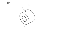
図1は、本発明の圧接ひずみ試験方法によって圧接ひずみを試験する紙送りローラの一例を示す斜視図である。
図1を参照して、この例の紙送りローラ1は、ゴムや熱可塑性エラストマ等を少なくとも含む成形材料を、中心に断面円形でかつ内径が一定の通孔2を有する筒状に成形するとともに、ゴムの場合は架橋させてなるものである。紙送りローラ1の外周面3は、通孔と同心状でかつ外径が一定の筒状に形成されている。
<Pressure welding strain test equipment>
FIG. 1 is a perspective view showing an example of a paper feed roller for testing the pressure welding strain by the pressure welding strain testing method of the present invention.
Referring to FIG. 1, a
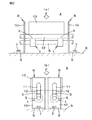
図2(a)は、本発明の圧接ひずみ試験方法のうち第一および第二工程を実施するために用いる圧接ひずみ試験装置の一例を示す正面図、図2(b)は側面図である。
図1、図2(a)(b)を参照して、この例の圧接ひずみ試験装置4は、紙送りローラ1をシャフト5に固定した状態で画像形成装置に組み込んで所定の部材を圧接させた状態を再現するためのものである。
FIG. 2 (a) is a front view showing an example of a pressure welding strain testing apparatus used for carrying out the first and second steps in the pressure welding strain testing method of the present invention, and FIG. 2 (b) is a side view.
Referring to FIGS. 1, 2 (a) and 2 (b), the pressure contact
かかる圧接ひずみ試験装置4は、図の例の場合、水平に配設された台盤6上に、ボルト7を介して着脱自在に取り付けられた4枚のL型アングル材8を備えている。
各L型アングル材8は、図示しないボルト穴を備え、図において下面を台盤6に当接させた状態で、ボルト7によって台盤6上に固定された固定平板部9と、当該固定平板部9の一端から直角に立ち上げられた支持平板部10とを一体に形成してなる。
In the case of the example shown in the figure, the pressure
Each L-
4枚のL型アングル材8は、2枚ずつを1組として、支持平板部10が互いに平行になるように一定間隔離間させるとともに、2組のL型アングル材8の2枚ずつの支持平板部10が同一面上に並ぶように当該2組を隣合せた状態で台盤6上に固定されている。
各支持平板部10には、台盤6に対して直交方向、すなわち鉛直方向に延びる長穴11が設けられている。
The four L-
Each support
長穴11には、紙送りローラ1を固定したシャフト5が挿通される。長穴11の、水平方向の幅はシャフト5の外径と略一致している。また長穴11の下端は、シャフト5を受容する半円形とされている。
それぞれの組のL型アングル材8は、互いに離間させた支持平板部10の長穴11の、各支持平板部10の鉛直方向、および水平方向の形成位置が一致するように台盤6上に固定されている。
A
Each set of L-shaped
シャフト5は、その全長が、互いに離間させた支持平板部10間の間隔よりも長めに設定されており、1組のL型アングル材8の支持平板部10の長穴11間に台盤6と平行、すなわち水平に架け渡された状態で圧接ひずみ試験装置4にセットされる。
シャフト5としては、後述する丸棒12を圧接させた際に自身が変形するおそれのない金属の丸棒が好適に用いられる。
The overall length of the
As the
また図の例の圧接ひずみ試験装置4は2組のL型アングル材8を備えるため、2本のシャフト5を同時にセットできる。
そのため、例えば1本のシャフト5に組成の異なる材料からなる複数個(図では2個)ずつの紙送りローラ1を固定して同時に圧接ひずみ試験をすることができ、効率的である。
In addition, since the pressure contact
For this reason, for example, a plurality of (two in the figure)
紙送りローラ1の実使用時に圧接される部材のモデルとしては、例えば当該部材がローラ状であるとき、図に示すように、当該部材と同径の丸棒12が用いられる。
またかかる丸棒12としては、圧接によって自身が変形するおそれのない金属の丸棒が好適に用いられる。
図の例では、シャフト5と同径の丸棒12を使用している。
As a model of a member to be pressed in actual use of the
Moreover, as this
In the illustrated example, a
かかる丸棒12を、1組のL型アングル材8の支持平板部10の長穴11間に架け渡したシャフト5に固定した紙送りローラ1の外周面3に、長穴11をガイドとして鉛直方向上方から当接させる。この際、丸棒12は、外径が長穴11の水平方向の幅と略一致するため、長穴11にガイドされて鉛直方向の上下動のみが許容される。
2本の丸棒12上には錘13が載置され、かかる丸棒12と錘13の荷重Fにより、当該2本の丸棒12が、長穴11にガイドされて、シャフト5に固定された個々の紙送りローラ1に鉛直上方から圧接される。
The
A
錘13の質量は、個々の紙送りローラ1に加える荷重×試験する紙送りローラ1の個数分から丸棒12の質量を差し引いた値に設定する。
例えば2本のシャフト5に2個ずつ計4個の紙送りローラ1を固定して試験を行う場合、個々の紙送りローラ1に600gの荷重を加えるには、錘13の質量を600×4=2400gから2本の丸棒12の質量を差し引いた値、言い換えれば錘13と2本の丸棒12の合計の質量を2400gとすればよい。
The mass of the
For example, when a test is performed with two
なお紙送りローラ1の実使用時に圧接されるローラ状の部材の径や外形が異なる場合は、丸棒12に代えて、長穴11に挿通される部分のみ丸棒12と外径が等しい丸棒状で、かつ紙送りローラ1に対して圧接される部分は径や外形の異なる部材を使用すればよい。
〈圧接ひずみ試験方法〉
上記圧接ひずみ試験装置4を用いて、本発明の圧接ひずみ試験方法を実施するには、まず被検体としての紙送りローラ1の通孔2に、例えばその内径よりも外径がわずかに大きいシャフト5を圧入することで、空転を生じないように互いに固定する。
In the case where the diameter and outer shape of the roller-like member to be pressed in actual use of the
<Pressure strain test method>
In order to carry out the pressure-contact strain test method of the present invention using the pressure-contact
図の例では、先に説明したように1本のシャフトに2個、計4個の紙送りローラ1を、2本のシャフト5に固定しているが、紙送りローラ1の個数は適宜変更できる。それに合わせて錘13の質量を変更すればよい。
次いで2本のシャフト5を、それぞれ圧接ひずみ試験装置4の2組のL型アングル材8の支持平板部10の長穴11間に台盤6と平行、すなわち水平に架け渡さした状態でセットする。
In the example shown in the figure, two
Next, the two
そして2本の丸棒12を、長穴11によってガイドさせながら、シャフト5に固定された個々の紙送りローラ1に鉛直上方から圧接させ、さらにその上に所定の質量の錘13を載せる。
次いでこの状態で、一定温度T1の高温環境下、一定時間静置(第一工程)したのち、圧接状態を維持しながら、温度T1より低い一定温度T2の環境下で一定時間静置する(第二工程)。
The two
Next, in this state, after standing for a certain period of time in a high temperature environment at a certain temperature T 1 (first step), it is allowed to stand for a certain period of time in an environment of a certain temperature T 2 lower than the temperature T 1 while maintaining the pressure contact state. (Second step).
第一工程の温度T1は40℃以上、250℃以下であるのが好ましい。
温度T1がこの範囲未満では、第一工程における圧接保持時間を長くしないと紙送りローラ1に十分な変形量の圧接ひずみを生じさせることができず、第三工程での変形量の測定が不正確になるおそれがある。また圧接保持時間が長くなって試験の効率が低下するおそれもある。
The temperature T 1 in the first step is preferably 40 ° C. or higher and 250 ° C. or lower.
At a temperature T 1 is less than this range, it is impossible to produce a strain pressure sufficient deformation amount unless a longer pressed retention time in the first step the
一方、温度T1が範囲を超える場合には、被検体としての紙送りローラ1を構成するゴム等の劣化等を生じるおそれがある。
なお変形量に寄与するゴム等の変形温度や、耐熱性に係わるゴム等の耐熱温度などはその種類によって異なるため、使用するゴム等に応じて上記の範囲内で適切な温度T1を選択するのが望ましい。
On the other hand, if the temperature T 1 is greater than a range, which may cause the deterioration of the rubber constituting the
The deformation temperature of rubber or the like that contributes to the amount of deformation and the heat resistance temperature of rubber or the like related to heat resistance vary depending on the type, so an appropriate temperature T 1 is selected within the above range depending on the rubber used. Is desirable.
例えばEPDMであれば、温度T1は40℃以上、特に50℃以上であるのが好ましく、150℃以下、特に120℃以下であるのが好ましい。
またふっ素ゴムなどの耐熱性のゴムの場合、温度T1は40℃以上、特に80℃以上であるのが好ましく、250℃以下、特に240℃以下であるのが好ましい。
また第一工程の圧接保持時間は2時間以上、中でも4時間以上、特に6時間以上であるのが好ましい。圧接保持時間が長いほど、紙送りローラ1に十分な変形量の圧接ひずみを生じさせることができる。
For example, in the case of EPDM, the temperature T 1 is preferably 40 ° C. or higher, particularly 50 ° C. or higher, preferably 150 ° C. or lower, particularly preferably 120 ° C. or lower.
In the case of heat-resistant rubber such as fluorine rubber, the temperature T 1 is preferably 40 ° C. or higher, particularly 80 ° C. or higher, and preferably 250 ° C. or lower, particularly 240 ° C. or lower.
Further, the pressure contact holding time in the first step is preferably 2 hours or more, more preferably 4 hours or more, and particularly preferably 6 hours or more. As the press-contact holding time is longer, a sufficient deformation amount of press-contact strain can be generated in the
ただし試験の効率を向上することを考慮すると、第一工程の圧接保持時間は168時間(1週間)以下、特に70時間以下であるのが好ましい。
また第一工程の温度T1と第二工程の温度T2の差は10℃以上、特に20℃以上であるのが好ましい。
かかる差が小さすぎる場合には、第二工程において、第一工程で生じさせた圧接ひずみを十分に固定できず、圧接を解除すると圧接ひずみが回復して第三工程での変形量の測定が不正確になるおそれがある。
However, in consideration of improving the efficiency of the test, the pressure contact holding time in the first step is preferably 168 hours (one week) or less, particularly preferably 70 hours or less.
Further, the difference between the temperature T 1 in the first step and the temperature T 2 in the second step is preferably 10 ° C. or more, particularly preferably 20 ° C. or more.
If this difference is too small, the pressure welding strain generated in the first step cannot be sufficiently fixed in the second step, and when the pressure welding is released, the pressure welding strain recovers and the deformation amount in the third step is measured. May be inaccurate.
ただし第二工程の温度T2が、第三工程での測定温度以下である場合には、測定時の温度上昇によって圧接ひずみが回復して正確な測定ができないおそれがある。そのため第二工程の温度T2は第三工程の測定温度付近、具体的には室温であるのが好ましい。
また第二工程の圧接保持時間は、紙送りローラ1やシャフト5を含む圧接ひずみ試験装置4の全体を温度T2まで十分に冷却するのに必要な時間より長ければよく、1時間以上、中でも2時間以上、特に4時間以上であるのが好ましい。
However the temperature T 2 of the second step, when it is determined temperature following the third step, there may not be an accurate measurement recovered strain pressure is the temperature rise at the time of measurement. Therefore the temperature T 2 of the second step around the measured temperature of the third step, preferably specifically a room temperature.
The pressure holding time of the second step may be longer than the time required to sufficiently cool the whole of the press-
ただし試験の効率を向上することを考慮すると、第二工程の圧接保持時間は48時間以下、特に24時間以下であるのが好ましい。
次いで圧接を解除して、圧接部分の紙送りローラ1の変形量を測定する(第三工程)。
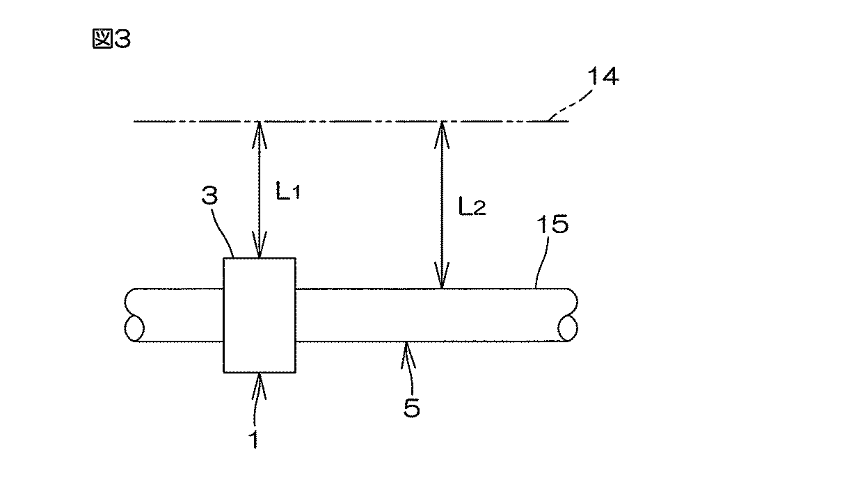
図3は、本発明の圧接ひずみ試験方法のうち第三工程において、紙送りローラの変形量を測定する方法の一例を説明する正面図である。図の例は、レーザー外径測定装置を用いた測定方法である。
However, in consideration of improving the efficiency of the test, the pressure contact holding time in the second step is preferably 48 hours or shorter, particularly 24 hours or shorter.
Next, the pressure contact is released, and the amount of deformation of the
FIG. 3 is a front view for explaining an example of a method for measuring the deformation amount of the paper feed roller in the third step of the pressure contact strain test method of the present invention. The example in the figure is a measuring method using a laser outer diameter measuring device.
すなわち図3を参照して、レーザー外径測定装置の、基準点からの距離を求めるモードで、基準点(直線14で示す)から紙送りローラ1の外周面3までの距離L1(mm)と、シャフト5の外周面15までの距離L2(mm)とを測定し、式(a):
肉厚t=L2−L1 (a)
によって、当該紙送りローラ1の肉厚t(mm)を求める。
That is, referring to FIG. 3, the distance L 1 (mm) from the reference point (shown by a straight line 14) to the outer
Thickness t = L 2 −L 1 (a)
Thus, the thickness t (mm) of the
この操作を、1つの紙送りローラ1の、丸棒12を圧接させていた位置と圧接させていなかった位置で実施して、丸棒12を圧接させていなかった位置の肉厚t0(mm)と、丸棒12を圧接させていた位置の肉厚t1(mm)とを求めて式(b):
変形量=t0−t1 (b)
によって変形量(mm)を求める。
This operation is performed at a position of one
Deformation amount = t 0 −t 1 (b)
To obtain the deformation (mm).
かかる変形量が小さいほど、紙送りローラ1は、他のローラと1箇所で接触した状態が比較的長期に亘って続いても、変形による圧接ひずみを生じにくいと判定することができる。
なお第二工程での圧接を解除してから、第三工程で変形量を測定するまでの期間は、一定に定めておけば特に制限はないが、圧接解除後、測定温度で30分間以上であるのが好ましく24時間以下であるのが好ましい。
As the amount of deformation is smaller, the
The period from the release of the pressure welding in the second step to the measurement of the amount of deformation in the third step is not particularly limited as long as it is fixed, but after the pressure welding is released, the measurement temperature is 30 minutes or more. It is preferably 24 hours or less.
圧接解除後、測定開始までに30分間以上置くのが好ましいのは、圧縮解除直後では、圧接を解除したことによる圧接ひずみの回復途中や、あるいは第二工程と第三工程の温度差で圧接ひずみが変化している途中で正確な測定ができないおそれがあるためである。
また圧接解除後24時間以内に測定するのが好ましいのは、圧接ひずみが大きく回復して変形量の測定が不正確になるおそれがあるためである。
It is preferable to leave it for 30 minutes or more before starting measurement after releasing the pressure welding. Immediately after releasing the compression, the pressure welding strain is in the process of recovering the pressure welding strain due to the release of the pressure welding or due to the temperature difference between the second and third steps. This is because there is a possibility that accurate measurement may not be possible while the value is changing.
The reason why the measurement is preferably performed within 24 hours after the release of the pressure contact is that there is a possibility that the measurement of the deformation amount may become inaccurate due to a large recovery of the pressure contact strain.
なお本発明の圧接ひずみの測定方法は、以上で説明した例には限定されない。
例えば被検体は、紙送りローラそのものには限定されず、当該紙送りローラから採取した、あるいは紙送りローラと同じ材料を用いて別個に作製したサンプルであってもよい。その場合、第一ないし第三工程を実施する装置は図の例には限定されず、当該第一ないし第三工程を、規定された所定の条件で実施しうる任意の器具や装置を用いることができる。
In addition, the measuring method of the welding distortion of this invention is not limited to the example demonstrated above.
For example, the subject is not limited to the paper feed roller itself, and may be a sample collected from the paper feed roller or separately made using the same material as the paper feed roller. In that case, the apparatus for carrying out the first to third steps is not limited to the example shown in the figure, and any apparatus or device that can carry out the first to third steps under prescribed prescribed conditions is used. Can do.
例えば第三工程の変形量の測定には、例えばダイヤルゲージやノギス、測定顕微鏡(光学式、レーザー式)等の任意の器具や装置を用いることができる。
また以上で説明した図の例であるか、その他の例であるかを問わず、荷重その他の条件は特に限定されるものではない。例えば図の例のように紙送りローラそのものについて試験する場合は実使用条件に合わせた荷重をかけて試験をするのが好ましいが、比較試験で有意差が出やすい荷重その他の条件を試験担当者が目的に応じて任意に設定してもよい。
For example, for measuring the amount of deformation in the third step, for example, an arbitrary instrument or apparatus such as a dial gauge, a caliper, or a measurement microscope (optical type, laser type) can be used.
Further, the load and other conditions are not particularly limited regardless of whether the example is the above-described diagram or other examples. For example, as shown in the example in the figure, when testing the paper feed roller itself, it is preferable to apply the load according to the actual usage conditions, but the test personnel should specify the load and other conditions that are likely to cause a significant difference in the comparison test. May be arbitrarily set according to the purpose.
圧接ひずみ量はmmではなく、試験前の寸法に対する百分率(ひずみ率)等で表してもよいし、その他適宜の表現をしてもよい。また合否判定についても適宜判断基準を設定すればよく、制限されるものではない。 The pressure welding strain amount is not expressed in mm, but may be expressed as a percentage (strain rate) with respect to the dimension before the test, or may be expressed as appropriate. In addition, it is only necessary to set a determination criterion as appropriate for pass / fail determination, and the determination is not limited.
〈試験例1〉
(ゴム組成物の調製)
下記表1に示す各成分を3Lニーダーおよびオープンロールを用いて混合して、被検体1〜3のもとになるゴム組成物を調製した。
<Test Example 1>
(Preparation of rubber composition)
Each component shown in Table 1 below was mixed using a 3 L kneader and an open roll to prepare a rubber composition as a basis for the
表中の各成分は下記のとおり。
EPDM(I):非油展、住友化学(株)製のエスプレン(登録商標)505A、エチレン含量:50質量%、ジエン含量:質量9.5%
EPDM(II):非油展、ダウ・ケミカル社製のNORDEL(ノーデル、登録商標)IP4770P、エチレン含量:70質量%、ジエン含量:4.9質量%
イソプレンゴム:日本ゼオン(株)製のニポール(登録商標)IR2200
スチレンブタジエンゴム:非油展、住友化学(株)製のエマルジョンSBR1502
カーボンブラック:HAF、東海カーボン(株)製の商品名シースト3
重質炭酸カルシウム:白石工業(株)製のホワイトン(登録商標)BF−300
過酸化物架橋剤:ジクミルパーオキシド(DCP)、日油(株)製のパークミル(登録商標)D
共架橋剤:トリアリルイソシアヌレート(TAIC)、日本化成(株)製のタイク(登録商標)
(大型試験片の作製)
調製したゴム組成物を、トランスファー成形金型を用いて160℃×30分間の条件でプレス架橋させて、日本工業規格JIS K6262:2013「加硫ゴム及び熱可塑性ゴム−常温,高温及び低温における圧縮永久ひずみの求め方」に規定された被検体1〜3の大型試験片を作製した。
Each component in the table is as follows.
EPDM (I): Non-oil exhibition, Esprene (registered trademark) 505A manufactured by Sumitomo Chemical Co., Ltd., ethylene content: 50 mass%, diene content: mass 9.5%
EPDM (II): non-oil exhibition, NORDEL (Nodel, registered trademark) IP4770P manufactured by Dow Chemical Co., ethylene content: 70% by mass, diene content: 4.9% by mass
Isoprene rubber: Nipol (registered trademark) IR2200 manufactured by Nippon Zeon Co., Ltd.
Styrene butadiene rubber: Non-oil exhibition, Emulsion SBR1502 manufactured by Sumitomo Chemical Co., Ltd.
Carbon black: HAF,
Heavy calcium carbonate: White (registered trademark) BF-300 manufactured by Shiroishi Kogyo Co., Ltd.
Peroxide crosslinking agent: Dicumyl peroxide (DCP), Park Mill (registered trademark) D manufactured by NOF Corporation
Co-crosslinking agent: triallyl isocyanurate (TAIC), Taik (registered trademark) manufactured by Nippon Kasei Co., Ltd.
(Manufacture of large specimens)
The prepared rubber composition was press-crosslinked under the conditions of 160 ° C. × 30 minutes using a transfer molding die. Large test pieces of
(紙送りローラの作製)
調製したゴム組成物を、トランスファー成形金型を用いて160℃×30分間の条件でプレス架橋させて、紙送りローラのもとになる内径5.4mmの円筒体を形成した。
次いでこの円筒体の通孔に外径6mmのシャフトを圧入して固定した状態で、その外周面を円筒研削盤を用いて外径が13mmとなるように研磨したのち、幅8mmにカットして被検体1〜3の紙送りローラを作製した。シャフトとの径差に基づく締め代は10%であった。
(Production of paper feed roller)
The prepared rubber composition was press-crosslinked under a condition of 160 ° C. × 30 minutes using a transfer molding die to form a cylindrical body having an inner diameter of 5.4 mm as a base for the paper feed roller.
Next, in a state where a shaft having an outer diameter of 6 mm is press-fitted and fixed to the through hole of the cylindrical body, the outer peripheral surface is polished using a cylindrical grinder so that the outer diameter becomes 13 mm, and then cut into a width of 8 mm. Paper feed rollers for the
なお紙送りローラは、1本のシャフトに2個を固定したものを、各被検体ごとに2本用意した。
〈圧縮永久ひずみ試験〉
各被検体の大型試験片を用いて、上記JIS K6262所載の測定方法に則って圧縮永久ひずみ率(%)を求めた。
Two paper feed rollers, each of which is fixed to one shaft, were prepared for each subject.
<Compression set test>
Using a large test piece of each subject, the compression set (%) was determined in accordance with the measurement method described in JIS K6262.
すなわち大型試験片を厚み方向に25%圧縮した状態で、オーブン中で70℃×24時間静置し、次いでオーブンから取り出した直後に圧縮を解除して30分間室温で静置したのち厚みを測定し、圧縮永久ひずみ率(%)を求めた。
〈圧接ひずみ試験〉
上述のように各被検体の紙送りローラ1を1本のシャフト5に2個ずつ固定したもの2本用意し、それを図2(a)(b)に示す圧接ひずみ試験装置4に組み込んだ。そして2本の丸棒12を個々の紙送りローラ1に鉛直上方から圧接させ、さらにその上に所定の質量の錘13を載せた。
In other words, a large test piece was compressed 25% in the thickness direction, left in an oven at 70 ° C. for 24 hours, then released immediately after being taken out of the oven and then left at room temperature for 30 minutes to measure the thickness. The compression set rate (%) was determined.
<Pressure strain test>
As described above, two
錘13と2本の丸棒12の合計の質量は2400gとし、個々の紙送りローラ1には600gの荷重を加えた。
次いでこの状態で温度T1=70℃、圧接保持時間:24時間の条件で静置(第一工程)したのち、圧接状態を維持しながら温度T2=23℃、圧接保持時間:8時間の条件で静置した(第二工程)。
The total mass of the
Next, after standing in this state under conditions of temperature T 1 = 70 ° C. and pressure contact holding time: 24 hours (first step), temperature T 2 = 23 ° C. and pressure holding time: 8 hours while maintaining the pressure contact state. It left still on conditions (2nd process).
次いで圧接を解除して23℃で1時間経過後に、23℃の環境下、先に説明した図3に示す方法によって、1つの紙送りローラ1の丸棒12を圧接させていなかった位置の肉厚t0(mm)と、丸棒12を圧接させていた位置の肉厚t1(mm)とを求めて式(b):
変形量=t0−t1 (b)
によって変形量(mm)を求める操作を、同じ被検体の4個の紙送りローラ1について実施し、平均値を求めてその被検体の変形量(mm)とした。
Next, after the pressure contact is released and one hour has passed at 23 ° C., the meat at the position where the
Deformation amount = t 0 −t 1 (b)
The operation for obtaining the deformation amount (mm) was performed on the four
結果を表2に示す。 The results are shown in Table 2.
表2の結果より、被検体1は被検体2、3に比べて圧縮永久ひずみ率が2ポイント大きいものの、圧接ひずみ試験による変形量は被検体2、3よりも小さいことが判った。この被検体1の紙送りローラの、客先での実機試験の結果は合格であった。
また被検体2、3は圧縮永久ひずみ率が同じであったが、圧接ひずみ試験による変形量は、被検体2よりも被検体3の方が大きいことが判った。客先での実機試験の結果は、被検体2が合格、被検体3が不合格であった。
From the results in Table 2, it was found that the
The
そして以上の結果から、本発明の圧接ひずみ試験方法によれば、従来の圧縮永久ひずみ率の結果からは判別できない実機試験による合格、不合格を、実機試験前に判別できることが判った。
〈試験例2〜4〉
試験例1で作製したのと同じ被検体2、3の紙送りローラについて、第一工程の温度T1と圧接保持時間、ならびに第二工程の温度T2と圧接保持時間を、それぞれ表3に示す値としたこと以外は試験例1と同様にして変形量を求めた。
From the above results, it has been found that, according to the pressure contact strain test method of the present invention, it is possible to determine pass / fail by the actual machine test that cannot be determined from the result of the conventional compression set rate before the actual machine test.
<Test Examples 2 to 4>
For the paper feed roller of the
〈試験例5、6〉
試験例1で作製したのと同じ被検体2、3の紙送りローラについて、第一工程の温度T1と圧接保持時間を、それぞれ表3に示す値とし、なおかつ第二工程を省略したこと以外は試験例1と同様にして変形量を求めた。
以上の結果を、試験例1の被検体2、3の結果と併せて表3に示す。
<Test Examples 5 and 6>
For the paper feed roller of the
The above results are shown in Table 3 together with the results of the
表3の試験例5の結果より、高温環境下で第一工程を実施したのち第二工程を省略した場合には、上記第一工程での変形を固定できないため、被検体2、3の変形量の差が小さくなって、両被検体の、実機試験での合格、不合格を予測できないことが判った。
また試験例6の結果より、第一および第二工程に代えて室温で荷重をかけるだけでは十分に変形できないため、やはり被検体2、3の変形量の差が小さくなって、両被検体の、実機試験での合格、不合格を予測できないことが判った。
From the result of Test Example 5 in Table 3, when the second step is omitted after the first step is performed in a high-temperature environment, the deformation in the first step cannot be fixed. It became clear that the difference in quantity was small, and it was impossible to predict the passing or failing of both specimens in the actual machine test.
In addition, from the results of Test Example 6, since it cannot be sufficiently deformed only by applying a load at room temperature instead of the first and second steps, the difference in deformation amount between the
これに対し試験例1〜4の結果より、高温環境下での第一工程とそれより低温での第二工程を実施する本発明の圧接ひずみ試験方法によれば、被検体2、3の変形量の差が大きいことから、両被検体の、実機試験での合格、不合格を予測できることが判った。
また試験例1〜4の結果より、被検体2、3の、実機試験での合格、不合格をより一層正確に予測すべく両被検体の変形量の差を大きくするには、第一工程の温度T1を40℃以上、特に50℃以上、温度T1とT2の差を10℃以上、特に20℃以上とし、なおかつ第二工程の温度T2を室温付近とするのが好ましいことが判った。
On the other hand, from the results of Test Examples 1 to 4, according to the pressure strain test method of the present invention in which the first step under a high temperature environment and the second step at a lower temperature are performed, the deformation of the
In addition, from the results of Test Examples 1 to 4, the first step is to increase the difference in deformation amount between the two specimens in order to more accurately predict the passing and failing of the
また第一工程の圧接保持時間は2時間以上、中でも4時間以上、特に6時間以上で、かつ第二工程の圧接保持時間は1時間以上、中でも2時間以上、特に4時間以上であるのが好ましいことが判った。 Further, the pressure holding time in the first step is 2 hours or more, especially 4 hours or more, particularly 6 hours or more, and the pressure holding time in the second step is 1 hour or more, especially 2 hours or more, particularly 4 hours or more. It turned out to be preferable.
1 紙送りローラ
2 通孔
3 外周面
4 圧接ひずみ試験装置
5 シャフト
6 台盤
7 ボルト
8 L型アングル材
9 固定平板部
10 支持平板部
11 長穴
12 丸棒
13 錘
14 直線
15 外周面
L1 距離
L2 距離
DESCRIPTION OF
Claims (5)
上記圧接状態を維持しながら、上記温度T1より低い一定温度T2の環境下で一定時間静置する工程(第二工程)、および
圧接を解除して、紙送りローラまたはそのサンプルの変形量を測定する工程(第三工程)、
を含む紙送りローラの圧接ひずみ試験方法。 A paper feed roller or the sample as a subject, a constant temperature high-temperature environment of T 1, step for a predetermined time to stand while applying a constant load (first step),
While maintaining the above pressure contact state, a step of a predetermined time stand in an environment of the temperature T 1 of lower than a predetermined temperature T 2 (second step), and to release the pressure contact, the paper feed roller or the amount of deformation of the sample Measuring step (third step),
Pressure strain test method for paper feed rollers including
Priority Applications (1)
| Application Number | Priority Date | Filing Date | Title |
|---|---|---|---|
| JP2013255885A JP6279306B2 (en) | 2013-12-11 | 2013-12-11 | IDC test method |
Applications Claiming Priority (1)
| Application Number | Priority Date | Filing Date | Title |
|---|---|---|---|
| JP2013255885A JP6279306B2 (en) | 2013-12-11 | 2013-12-11 | IDC test method |
Publications (2)
| Publication Number | Publication Date |
|---|---|
| JP2015114193A true JP2015114193A (en) | 2015-06-22 |
| JP6279306B2 JP6279306B2 (en) | 2018-02-14 |
Family
ID=53528119
Family Applications (1)
| Application Number | Title | Priority Date | Filing Date |
|---|---|---|---|
| JP2013255885A Expired - Fee Related JP6279306B2 (en) | 2013-12-11 | 2013-12-11 | IDC test method |
Country Status (1)
| Country | Link |
|---|---|
| JP (1) | JP6279306B2 (en) |
Cited By (1)
| Publication number | Priority date | Publication date | Assignee | Title |
|---|---|---|---|---|
| CN117842471A (en) * | 2024-03-07 | 2024-04-09 | 咸宁久康医用材料有限公司 | A thermoplastic heat-welding device and a method of using the same |
Citations (13)
| Publication number | Priority date | Publication date | Assignee | Title |
|---|---|---|---|---|
| JP2002104686A (en) * | 2000-09-29 | 2002-04-10 | Hitachi Metals Ltd | Sheet conveying roll and manufacturing method thereof |
| JP2002293448A (en) * | 2001-03-30 | 2002-10-09 | Bridgestone Corp | Paper feed roller and image forming apparatus |
| JP2003215872A (en) * | 2002-01-18 | 2003-07-30 | Canon Inc | Elastic roller, process cartridge, and image forming apparatus |
| JP2005242191A (en) * | 2004-02-27 | 2005-09-08 | Canon Chemicals Inc | Foam elastic body roller and manufacturing method thereof |
| JP2006162675A (en) * | 2004-12-02 | 2006-06-22 | Bridgestone Corp | Elastic roller and method for designing elastic roller |
| US20060269327A1 (en) * | 2005-05-31 | 2006-11-30 | Sumitomo Rubber Industries, Ltd. | Semiconductive rubber member |
| JP2008003480A (en) * | 2006-06-26 | 2008-01-10 | Shin Etsu Polymer Co Ltd | Elastic roller, fixing device for image forming apparatus, and image forming apparatus |
| JP2010180357A (en) * | 2009-02-06 | 2010-08-19 | Sumitomo Rubber Ind Ltd | Semiconducting rubber composition and semiconducting rubber roller using the same |
| JP2012008237A (en) * | 2010-06-23 | 2012-01-12 | Canon Inc | Developing roller and method for manufacturing the same |
| JP2012022076A (en) * | 2010-07-13 | 2012-02-02 | Canon Inc | Method for manufacturing elastic roller |
| JP2012091506A (en) * | 2010-09-30 | 2012-05-17 | Canon Inc | Method for manufacturing regenerated elastic roller |
| JP2012108358A (en) * | 2010-11-18 | 2012-06-07 | Canon Inc | Developing roller, manufacturing method of developing roller, developing device, electrophotographic process cartridge, and electrophotographic image forming apparatus |
| JP2013144789A (en) * | 2011-12-13 | 2013-07-25 | Nitto Denko Corp | Non-slip material |
-
2013
- 2013-12-11 JP JP2013255885A patent/JP6279306B2/en not_active Expired - Fee Related
Patent Citations (13)
| Publication number | Priority date | Publication date | Assignee | Title |
|---|---|---|---|---|
| JP2002104686A (en) * | 2000-09-29 | 2002-04-10 | Hitachi Metals Ltd | Sheet conveying roll and manufacturing method thereof |
| JP2002293448A (en) * | 2001-03-30 | 2002-10-09 | Bridgestone Corp | Paper feed roller and image forming apparatus |
| JP2003215872A (en) * | 2002-01-18 | 2003-07-30 | Canon Inc | Elastic roller, process cartridge, and image forming apparatus |
| JP2005242191A (en) * | 2004-02-27 | 2005-09-08 | Canon Chemicals Inc | Foam elastic body roller and manufacturing method thereof |
| JP2006162675A (en) * | 2004-12-02 | 2006-06-22 | Bridgestone Corp | Elastic roller and method for designing elastic roller |
| US20060269327A1 (en) * | 2005-05-31 | 2006-11-30 | Sumitomo Rubber Industries, Ltd. | Semiconductive rubber member |
| JP2008003480A (en) * | 2006-06-26 | 2008-01-10 | Shin Etsu Polymer Co Ltd | Elastic roller, fixing device for image forming apparatus, and image forming apparatus |
| JP2010180357A (en) * | 2009-02-06 | 2010-08-19 | Sumitomo Rubber Ind Ltd | Semiconducting rubber composition and semiconducting rubber roller using the same |
| JP2012008237A (en) * | 2010-06-23 | 2012-01-12 | Canon Inc | Developing roller and method for manufacturing the same |
| JP2012022076A (en) * | 2010-07-13 | 2012-02-02 | Canon Inc | Method for manufacturing elastic roller |
| JP2012091506A (en) * | 2010-09-30 | 2012-05-17 | Canon Inc | Method for manufacturing regenerated elastic roller |
| JP2012108358A (en) * | 2010-11-18 | 2012-06-07 | Canon Inc | Developing roller, manufacturing method of developing roller, developing device, electrophotographic process cartridge, and electrophotographic image forming apparatus |
| JP2013144789A (en) * | 2011-12-13 | 2013-07-25 | Nitto Denko Corp | Non-slip material |
Cited By (1)
| Publication number | Priority date | Publication date | Assignee | Title |
|---|---|---|---|---|
| CN117842471A (en) * | 2024-03-07 | 2024-04-09 | 咸宁久康医用材料有限公司 | A thermoplastic heat-welding device and a method of using the same |
Also Published As
| Publication number | Publication date |
|---|---|
| JP6279306B2 (en) | 2018-02-14 |
Similar Documents
| Publication | Publication Date | Title |
|---|---|---|
| US11598815B2 (en) | Battery test system and battery test method | |
| Dai et al. | Poking and bulging of suspended thin sheets: Slippage, instabilities, and metrology | |
| TW201234002A (en) | Compression testing device for testing materials automatically | |
| US12331179B2 (en) | Methods of evaluating and producing composite material, and composite material | |
| JP6279306B2 (en) | IDC test method | |
| US9539744B2 (en) | Semiconductive roller and production method therefor | |
| JP2017083182A (en) | Performance evaluation method and performance evaluation apparatus | |
| JP5945469B2 (en) | Pressure sensor | |
| RU2401848C2 (en) | Cold shrink article and preparation method thereof | |
| Porter et al. | Crosslink density and its distribution in heat and oil resistant elastomers by double quantum nuclear magnetic resonance | |
| Lu et al. | Influence of in situ reactive interphase with graft copolymer on shear and extensional rheology in a model bilayered polymer system | |
| JP6075246B2 (en) | Rubber seal material life evaluation method | |
| CN105945566A (en) | Automobile bearing bracket press fitting error proofing device | |
| JP5498190B2 (en) | Rubber tube | |
| JP6416166B2 (en) | Electrical property measuring apparatus, rubber composition inspection method, and rubber product manufacturing method | |
| JP2007113944A (en) | Measuring instrument of viscoelasticity, and measuring method of viscoelasticity | |
| JP2020085776A (en) | Rubber inspection method | |
| Sinha et al. | Development of fluorocarbon rubber for backup seals of sodium cooled fast breeder reactor | |
| Wahab et al. | Correlation between compression-set and compression stress-relaxation of epichlorohydrin elastomers | |
| JP4516069B2 (en) | Conductive roller | |
| JP6531891B2 (en) | Method of manufacturing fixing / pressure roll and method of manufacturing fixing device | |
| Salazar | Developments of interlaboratory comparisons on pressure measurements in the Philippines | |
| JP2012068502A (en) | Blade member, manufacturing method thereof, method for evaluating blade member, and blade member device | |
| JP6515767B2 (en) | Detection roller and sheet thickness detection device | |
| Auffenberg | Evaluating Rubber Aging on Tire Durability: Quantitative Evaluation of Rubber Aging |
Legal Events
| Date | Code | Title | Description |
|---|---|---|---|
| A621 | Written request for application examination |
Free format text: JAPANESE INTERMEDIATE CODE: A621 Effective date: 20161003 |
|
| A977 | Report on retrieval |
Free format text: JAPANESE INTERMEDIATE CODE: A971007 Effective date: 20170608 |
|
| A131 | Notification of reasons for refusal |
Free format text: JAPANESE INTERMEDIATE CODE: A131 Effective date: 20170615 |
|
| A521 | Request for written amendment filed |
Free format text: JAPANESE INTERMEDIATE CODE: A523 Effective date: 20170721 |
|
| TRDD | Decision of grant or rejection written | ||
| A01 | Written decision to grant a patent or to grant a registration (utility model) |
Free format text: JAPANESE INTERMEDIATE CODE: A01 Effective date: 20171221 |
|
| A61 | First payment of annual fees (during grant procedure) |
Free format text: JAPANESE INTERMEDIATE CODE: A61 Effective date: 20180117 |
|
| R150 | Certificate of patent or registration of utility model |
Ref document number: 6279306 Country of ref document: JP Free format text: JAPANESE INTERMEDIATE CODE: R150 |
|
| LAPS | Cancellation because of no payment of annual fees |