JP2015114126A - Vehicle location detection device - Google Patents
Vehicle location detection device Download PDFInfo
- Publication number
- JP2015114126A JP2015114126A JP2013254217A JP2013254217A JP2015114126A JP 2015114126 A JP2015114126 A JP 2015114126A JP 2013254217 A JP2013254217 A JP 2013254217A JP 2013254217 A JP2013254217 A JP 2013254217A JP 2015114126 A JP2015114126 A JP 2015114126A
- Authority
- JP
- Japan
- Prior art keywords
- vehicle
- calculated
- road
- vehicle position
- image
- Prior art date
- Legal status (The legal status is an assumption and is not a legal conclusion. Google has not performed a legal analysis and makes no representation as to the accuracy of the status listed.)
- Pending
Links
Images

Classifications
-
- G—PHYSICS
- G08—SIGNALLING
- G08G—TRAFFIC CONTROL SYSTEMS
- G08G1/00—Traffic control systems for road vehicles
- G08G1/09—Arrangements for giving variable traffic instructions
- G08G1/0962—Arrangements for giving variable traffic instructions having an indicator mounted inside the vehicle, e.g. giving voice messages
- G08G1/0968—Systems involving transmission of navigation instructions to the vehicle
- G08G1/0969—Systems involving transmission of navigation instructions to the vehicle having a display in the form of a map
-
- G—PHYSICS
- G01—MEASURING; TESTING
- G01C—MEASURING DISTANCES, LEVELS OR BEARINGS; SURVEYING; NAVIGATION; GYROSCOPIC INSTRUMENTS; PHOTOGRAMMETRY OR VIDEOGRAMMETRY
- G01C21/00—Navigation; Navigational instruments not provided for in groups G01C1/00 - G01C19/00
- G01C21/26—Navigation; Navigational instruments not provided for in groups G01C1/00 - G01C19/00 specially adapted for navigation in a road network
- G01C21/28—Navigation; Navigational instruments not provided for in groups G01C1/00 - G01C19/00 specially adapted for navigation in a road network with correlation of data from several navigational instruments
- G01C21/30—Map- or contour-matching
-
- G—PHYSICS
- G01—MEASURING; TESTING
- G01C—MEASURING DISTANCES, LEVELS OR BEARINGS; SURVEYING; NAVIGATION; GYROSCOPIC INSTRUMENTS; PHOTOGRAMMETRY OR VIDEOGRAMMETRY
- G01C21/00—Navigation; Navigational instruments not provided for in groups G01C1/00 - G01C19/00
- G01C21/26—Navigation; Navigational instruments not provided for in groups G01C1/00 - G01C19/00 specially adapted for navigation in a road network
- G01C21/34—Route searching; Route guidance
- G01C21/36—Input/output arrangements for on-board computers
- G01C21/3602—Input other than that of destination using image analysis, e.g. detection of road signs, lanes, buildings, real preceding vehicles using a camera
Landscapes
- Engineering & Computer Science (AREA)
- Radar, Positioning & Navigation (AREA)
- Remote Sensing (AREA)
- Physics & Mathematics (AREA)
- General Physics & Mathematics (AREA)
- Automation & Control Theory (AREA)
- Computer Vision & Pattern Recognition (AREA)
- Navigation (AREA)
- Traffic Control Systems (AREA)
Abstract
Description
本発明は、車両で用いられる自車位置検出装置に関する。 The present invention relates to a vehicle position detection device used in a vehicle.
車両に搭載される自車位置検出装置は、自車両の現在位置(自車位置)を検出し、運転者に対して、自車位置周辺の地図画像の表示及び地図画像上の車両の位置の表示を行う。自車位置を算出する方法としては、自車両の挙動変化を検出する自立センサの検出値に基づいて自車位置を更新する自立航法が周知である。自立センサとしては、前述の自車両の挙動変化として移動距離を検出するための車速センサや、車両の走行方向を検出するためのジャイロスコープ等が挙げられる。ただし、これらの自立センサは検出値に誤差を有するため、走行距離の増加に伴って、誤差が積算されて自立航法による自車位置と実際の自車位置とのずれが大きくなる。そこで、このような誤差による自車位置のずれを、GPS(Global Positioning System)等で用いられる人工衛星からの測位信号に基づいて補正する技術が開発されている。 The own vehicle position detection device mounted on the vehicle detects the current position of the own vehicle (own vehicle position), and displays a map image around the own vehicle position and the vehicle position on the map image to the driver. Display. As a method for calculating the vehicle position, a self-contained navigation method is known in which the vehicle position is updated based on a detection value of a self-supporting sensor that detects a change in the behavior of the vehicle. Examples of the self-supporting sensor include a vehicle speed sensor for detecting a moving distance as the behavior change of the host vehicle, a gyroscope for detecting the traveling direction of the vehicle, and the like. However, since these self-supporting sensors have an error in the detected value, the errors are integrated with an increase in the travel distance, and the difference between the own vehicle position by the self-contained navigation and the actual own vehicle position becomes large. In view of this, a technique has been developed for correcting the deviation of the position of the vehicle due to such an error based on a positioning signal from an artificial satellite used in a GPS (Global Positioning System) or the like.
特許文献1には、走行距離が所定値以上となった場合に、自立航法により算出した自車位置を、GPSの測位信号に基づいて補正する技術が開示されている。
しかしながら、GPSの測位信号に基づく自車位置の検出は、状況によっては検出精度が低くなる場合がある。前述した特許文献1に記載の技術では、GPSの測位信号に基づいて自車位置を補正するため、状況によっては自車位置を精度よく検出できないという問題があった。
However, the detection accuracy of the vehicle position based on the GPS positioning signal may be low depending on the situation. In the technique described in
本発明は、こうした問題に鑑みなされたものであり、自車位置を精度よく検出するための技術を提供することを目的としている。 The present invention has been made in view of these problems, and an object thereof is to provide a technique for accurately detecting the position of the vehicle.
本発明の一側面は、車両で用いられる自車位置検出装置であって、画像生成手段と、標示認識手段と、地図データ取得手段と、位置補正手段とを備える。画像生成手段は、自車両に取り付けられた撮像装置からの撮像情報に基づいて、自車両周辺の道路を鉛直方向に見下ろした撮像画像を生成する。標示認識手段は、撮像画像において、道路に描画された道路標示の形状を認識する。地図データ取得手段は、道路標示の形状が含まれた地図画像を表す地図データを取得する。位置補正手段は、標示認識手段により認識された道路標示の形状と、地図画像に含まれる道路標示であって自車両周辺に存在する道路標示の形状と、を対比して自車両の絶対位置を補正する。 One aspect of the present invention is an own vehicle position detection device used in a vehicle, and includes an image generation unit, a sign recognition unit, a map data acquisition unit, and a position correction unit. The image generation means generates a captured image in which a road around the host vehicle is looked down in a vertical direction based on imaging information from an imaging device attached to the host vehicle. The sign recognition means recognizes the shape of the road sign drawn on the road in the captured image. The map data acquisition means acquires map data representing a map image including the shape of the road marking. The position correction means compares the shape of the road sign recognized by the sign recognition means with the shape of the road sign included in the map image and existing around the own vehicle to determine the absolute position of the own vehicle. to correct.
このような構成によれば、地図画像と撮像画像との対比に基づいて自車位置を特定するため、GPSの測位信号に基づいて自車位置を検出する場合と比べて、自車位置を精度よく検出することが可能となる。 According to such a configuration, since the vehicle position is specified based on the comparison between the map image and the captured image, the vehicle position is more accurate than when the vehicle position is detected based on the GPS positioning signal. It is possible to detect well.
なお、特許請求の範囲に記載した括弧内の符号は、一つの態様として後述する実施形態に記載の具体的手段との対応関係を示すものであって、本発明の技術的範囲を限定するものではない。 In addition, the code | symbol in the parenthesis described in the claim shows the correspondence with the specific means as described in embodiment mentioned later as one aspect, Comprising: The technical scope of this invention is limited is not.
以下、本発明が適用された実施形態について、図面を用いて説明する。
[1.構成]
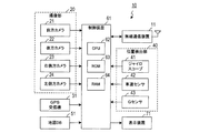
図1に示す本発明の自車位置検出装置10は、例えばナビゲーション装置において現在位置を高精度に把握するために用いられ得る。自車位置検出装置10は、無線通信装置11、撮像部20、GPS受信機31、位置検出部40、地図データベース(地図DB)51、制御装置61、及び表示装置71を備える。
Embodiments to which the present invention is applied will be described below with reference to the drawings.
[1. Constitution]
The own vehicle
無線通信装置11は、自車両の周辺(電波の届く通信エリア内)に存在する他の車両と無線通信(車車間通信)を行うための装置である。
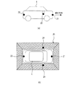
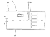
撮像部20は、図2(a)及び図2(b)に示すように、前方カメラ21、後方カメラ22、右側方カメラ23、及び左側方カメラ24を備える。前方カメラ21は、車両1の前方の道路を撮像するためのカメラであり、例えば車両1の前方側バンパの中央部に設置されている。後方カメラ22は、車両1の後方の道路を撮像するためのカメラであり、例えば車両1の後方側バンパの中央部に設置されている。右側方カメラ23は、車両1の右側方の道路を撮像するためのカメラであり、例えば車両1の右ドアミラーの先端位置に設置されている。左側方カメラ24は、車両1の左側方の道路を撮像するためのカメラであり、例えば車両1の左ドアミラーの先端位置に設置されている。このように、各カメラ21〜24は、自車両1の周辺の道路を撮像するように配置されている。なお、カメラ21〜24は、道路を撮像するために、水平方向よりも下方を向くように設置されている。
The
As shown in FIGS. 2A and 2B, the
カメラ21〜24は、撮像した画像を表す撮像情報(画像データ)を、制御装置61へ出力する。後述するように、制御装置61は、カメラ21〜24からの撮像情報に基づいて、自車両1の周辺の道路を鉛直方向上方から見下ろしたように視点変換した撮像画像を生成する。こうして生成される撮像画像において、カメラ21〜24による撮像範囲は、図2(b)でハッチング部25として示されるように、自車両1の全周をカバーする。なお、これらのカメラ21〜24は、4台とも同じ所定の周期で画像を撮像する。ここでいう所定の周期(撮像周期)とは、例えば、想定される最高速度での走行中に、少なくとも走行距離3m毎の頻度で撮像が行われる周期をいう。
The
GPS受信機31は、GPS用の人工衛星からの測位信号を受信し、受信した測位信号に基づいて、自車両1の現在位置である自車位置(緯度及び経度)を検出する。
位置検出部40は、ジャイロスコープ41、車速センサ42、及びGセンサ43を備える。ジャイロスコープ41は、自車両1に加えられる回転運動の大きさを検出する。車速センサ42は、自車両1の車軸に取り付けられたパルス発生器から出力される単位時間当たりのパルス数に基づいて当該車軸の回転速度を検出し、検出した回転速度に基づいて自車両1の速度を算出する。Gセンサ43は、自車両1の前後方向の加速度を検出する。
The
The
地図データベース(地図DB)51は、車両1の走行可能な道路が示された地図を表す地図データを記憶する記憶装置である。当該地図には、道路に描画されている道路標示の形状が詳細に示されている。ここでいう道路標示とは、道路の交通に関し、規制又は指示を表わす標示であり、路面に描かれた線、記号、又は文字である。具体的には、規制を表す標示として、転回禁止、追い越し禁止、駐停車禁止等が一例として挙げられ、指示を表す標示として、横断歩道、停止線、中央線、車線境界線等が一例として挙げられる。地図を表す地図データには、これらの道路標示の各部の寸法を特定可能なデータが含まれている。また、当該地図には、例えば図3に示すように、高層ビルの密集地帯のようにGPS用の人工衛星からの測位信号を受信することが困難なエリア(GPS受信困難エリアという)Qが示されている。
The map database (map DB) 51 is a storage device that stores map data representing a map on which roads on which the
表示装置71は、車両1の乗員に画像を表示するため装置である。例えば、表示画面には、地図データベース51から入力された地図データに基づく地図画像と、当該地図画像上に重畳して表示される自車位置を示すマークと、が表示される。
The
制御装置61は、CPU62、ROM63、RAM64を中心とする周知のマイクロコンピュータを中心に構成されている。制御装置61(具体的にはCPU62)は、ROM63に記憶されたプログラムに基づいて各種処理を実行する。制御装置61は、例えば、自車位置付近の地図を表す地図データを地図データベース51から読み込んで表示装置71に表示する処理や、当該地図に自車位置を示すマークを表示する処理等を実行する。
The
[2.処理]
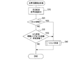
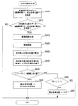
次に、制御装置61が実行する処理のうち、自車位置を算出するために周期的に実行される自車位置算出処理について、図4のフローチャートを用いて説明する。
[2. processing]
Next, of the processes executed by the
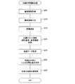
[2−1.自車位置算出処理]
まずS(ステップ)10では、位置検出部40からの各検出信号に基づいて、周知の自立航法によって自車位置を算出する。具体的には、前回算出した自車位置(既出自車位置)の算出時点からの挙動変化として、ジャイロスコープ41による検出信号に基づいて方位変化量を算出し、車速センサ42及びGセンサ43による検出信号に基づいて移動距離を算出する。そして、これらの挙動変化(方位変化量及び移動距離)に基づいて算出された変位量を、既出自車位置に加算して自車位置の更新を行う。なお、以下の説明では、実際の(真の)自車位置と区別するため、制御装置61が算出(推測)した自車位置を算出自車位置ともいう。
[2-1. Own vehicle position calculation process]
First, in S (step) 10, based on each detection signal from the
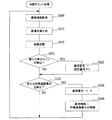
次にS20では、リセット周期であるか否かを判定する。具体的には、前回のリセット(自立航法によって蓄積された検出誤差をリセットするための処理であり、後述するS130、S175、S235、S440又はS450の処理)から所定のリセット期間が経過している場合に、リセット周期であると判定する。ここで、リセット周期でない場合はS30へ移行し、リセット周期である場合はS40へ移行してリセット処理を実行する。 Next, in S20, it is determined whether it is a reset cycle. Specifically, a predetermined reset period has elapsed since the previous reset (a process for resetting the detection error accumulated by the self-contained navigation, and the process of S130, S175, S235, S440 or S450 described later). In this case, it is determined that it is a reset cycle. Here, if it is not the reset period, the process proceeds to S30, and if it is the reset period, the process proceeds to S40 to execute the reset process.
S40のリセット処理は、地図画像に含まれる道路標示の形状と撮像画像に含まれる道路標示の形状とを対比して算出自車位置を補正する地図リセットや、対向車の位置及び対向車から取得した情報を用いて算出自車位置を補正する対向車リセットや、GPS用の人工衛星からの測位信号に基づいて算出自車位置を補正するGPSリセットなどを実行するための処理である。周知のように、位置検出部40が備える各自立センサ(ジャイロスコープ41、車速センサ42、及びGセンサ43)の検出信号(出力値)には誤差が含まれるため、自立航法では、走行距離の増加に伴ってこれらの誤差が積算される。この結果、自立航法に基づく算出自車位置と、実際の(真の)自車位置とのずれ(検出誤差)が大きくなる。リセット処理では、地図リセットやGPSリセットなどを実行することにより、このような検出誤差をリセット(補正)する。
The reset process of S40 is obtained from a map reset that corrects the calculated vehicle position by comparing the shape of the road marking included in the map image with the shape of the road marking included in the captured image, or acquired from the position of the oncoming vehicle and the oncoming vehicle. This is a process for executing an oncoming vehicle reset for correcting the calculated host vehicle position using the obtained information, a GPS reset for correcting the calculated host vehicle position based on a positioning signal from a GPS artificial satellite, and the like. As is well known, the detection signals (output values) of the independent sensors (
S20でリセット周期でないと判定した場合に移行するS30では、算出自車位置が、GPS受信困難エリアに対して所定距離未満の位置となったか否かを、地図データの表す地図画像に基づいて判定する。例えば、前述の図3に示すように、自車両1が自車位置Pから道なりに進むと仮定した場合に、GPS受信困難エリアQに自車両1が侵入するまでの距離が、所定距離未満となったか否かを判定する。
In S30, which is shifted when it is determined that the reset cycle is not determined in S20, it is determined based on the map image represented by the map data whether or not the calculated vehicle position is a position less than a predetermined distance from the GPS reception difficult area. To do. For example, as shown in FIG. 3 described above, when it is assumed that the
ここで、GPS受信困難エリアQに侵入するまでの距離が所定距離以上である場合は、本自車位置算出処理を終了する。一方、GPS受信困難エリアQに侵入するまでの距離が所定距離未満である場合は、S40へ移行してリセット処理を実行し、本自車位置算出処理を終了する。 Here, when the distance to enter the GPS reception difficulty area Q is equal to or greater than the predetermined distance, the present vehicle position calculation process is terminated. On the other hand, when the distance to enter the GPS reception difficulty area Q is less than the predetermined distance, the process proceeds to S40, the reset process is executed, and the present vehicle position calculation process is terminated.
GPS受信困難エリアに侵入するまでの距離が所定距離未満である場合にリセット処理を実行するのは、次の理由による。すなわち、GPS受信困難エリアでは、GPS用の人工衛星からの測位信号を受信することが困難であり、GPSリセットを実行できる機会が減るため、GPS受信困難エリアに侵入する前に、自立航法によって蓄積された検出誤差をリセットしておきたいからである。 The reset process is executed when the distance to enter the GPS reception difficult area is less than the predetermined distance for the following reason. In other words, it is difficult to receive positioning signals from GPS satellites in areas where GPS reception is difficult, and there are fewer opportunities to perform GPS resets. This is because it is desired to reset the detected error.
[2−2.リセット処理]
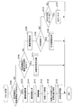
次に、自車位置算出処理のS40で実行されるリセット処理について、図5のフローチャートを用いて説明する。なお、図5のリセット処理において、S105〜S145が地図リセットのための処理であり、S150〜S160が対向車リセットのための処理であり、S175がGPSリセットの処理である。
[2-2. Reset processing]
Next, the reset process executed in S40 of the host vehicle position calculation process will be described using the flowchart of FIG. In the reset process of FIG. 5, S105 to S145 are processes for resetting the map, S150 to S160 are processes for resetting the oncoming vehicle, and S175 is a process of resetting GPS.
S100では、算出自車位置を中心とする所定範囲内に、何らかの特徴道路標示が存在するか否かを、地図データの表す地図画像に基づいて判定する。ここで、特徴道路標示が存在しない場合はS140へ移行する。一方、特徴道路標示が存在する場合は、S105へ移行する。 In S100, it is determined based on the map image represented by the map data whether or not any characteristic road marking exists within a predetermined range centered on the calculated vehicle position. Here, if there is no feature road marking, the process proceeds to S140. On the other hand, if there is a characteristic road marking, the process proceeds to S105.
特徴道路標示とは、図6に一例を示すように、道路に描画された複数種類の道路標示201〜205のうち、道路を区画するための区画線(白線204、205、及び破線状の白線203)のように、連続して描画されている道路標示を除いたものをいう。
The characteristic road marking is, as shown in FIG. 6 as an example, among the plural types of
地図リセットは、前述のように、地図画像に含まれる道路標示の形状と撮像画像に含まれる道路標示の形状とを対比して自車位置を特定する処理である。ここで、白線204、205や破線状の白線203のように連続して描画されている道路標示は、撮像画像にその一部しか写らない。このため、撮像画像に写ったこれらの形状が、連続して描画されている道路標示全体のどの部分に相当するかが特定できなければ、位置(緯度及び経度)を特定することができない。このため、S100では、連続して描画されている道路標示を除いた特徴道路標示を用いて、S105以降の処理を実行する。
As described above, the map reset is a process of identifying the vehicle position by comparing the shape of the road marking included in the map image with the shape of the road marking included in the captured image. Here, only a part of the road markings drawn continuously like the
例えば図6では、横断歩道201、及び横断歩道の手前に描画されている停止線202が、特徴道路標示に相当する。この他、図示していないが、転回禁止、駐停車禁止、進行方向等の種々の規制及び指示を表す標示が、特徴道路標示に相当する。
For example, in FIG. 6, the
S105では、撮像部20(カメラ21〜24)から出力される撮像情報を取得する。続くS110では、取得した撮像情報に基づいて、自車両周辺の道路を鉛直方向に見下ろした撮像画像を生成する。
In S105, imaging information output from the imaging unit 20 (
次にS115では、S110で生成した撮像画像において、特徴道路標示の形状を認識する。具体的には、道路に描画される様々な特徴道路標示のうち、S100で所定範囲内に存在すると判定された特徴道路標示(複数存在する場合は複数の特徴道路標示)に絞って、当該特徴道路標示を、周知のパタンマッチングの手法により、撮像画像において認識する。 Next, in S115, the shape of the characteristic road marking is recognized in the captured image generated in S110. Specifically, among the various characteristic road markings drawn on the road, the characteristic road markings determined to exist within the predetermined range in S100 (a plurality of characteristic road markings when there are a plurality of characteristic road markings) The road marking is recognized in the captured image by a known pattern matching technique.
続くS120では、算出自車位置を中心とする所定範囲内の地図画像を表す地図データ、すなわちS100で特徴道路標示の存在の有無を判定した地図画像を表す地図データを、地図データベース51から取得する。
In subsequent S120, map data representing a map image within a predetermined range centered on the calculated vehicle position, that is, map data representing a map image for which the presence or absence of a characteristic road marking is determined in S100 is acquired from the
次にS125では、S115で認識された撮像画像における特徴道路標示の形状と、S120で取得した地図データが表す地図画像に含まれる特徴道路標示の形状とを対比して、自車位置を特定する。すなわち、自車両1に対する各カメラ21〜24の配置が一定であり、かつ、撮像画像が一定の方法で生成されるという前提において、撮像画像における自車両1の位置は一定である。また、地図画像と撮像画像との対比によって、地図画像における撮像画像の位置(撮像範囲)が特定される。したがって、地図画像において自車位置が特定される。
Next, in S125, the vehicle position is identified by comparing the shape of the characteristic road marking in the captured image recognized in S115 with the shape of the characteristic road marking included in the map image represented by the map data acquired in S120. . That is, on the premise that the arrangement of the
S130では、算出自車位置を、S125で特定した自車位置に置き換えることで、算出自車位置の補正(検出誤差のリセット)を行う。そして、本リセット処理を終了する。
S100で所定範囲内に特徴道路標示が存在しないと判定した場合に移行するS140では、算出自車位置を中心とするS100と同様の所定範囲内に、破線状の白線が存在するか否かを判定する。前述の図6に一例として示すように、破線状の白線203は、複数の長方形の単位ライン210により構成されている。本ステップでは、算出自車位置を中心とする所定範囲内に破線状の白線(203)を構成する単位ライン(210)が存在するか否かを、地図データの表す地図画像に基づいて判定する。ここで、単位ラインが存在しない場合はS150へ移行し、単位ラインが存在する場合はS145へ移行する。
In S130, the calculated vehicle position is corrected (detection error reset) by replacing the calculated vehicle position with the vehicle position specified in S125. Then, the reset process ends.
In S140, which is shifted when it is determined in S100 that there is no characteristic road marking within the predetermined range, it is determined whether or not a dashed white line exists within the predetermined range similar to S100 centered on the calculated vehicle position. judge. As shown in FIG. 6 as an example, the broken
S145では、破線状の白線を利用して算出自車位置を補正する白線利用更新処理を実行する(詳細は後述する)。そして、本リセット処理を終了する。
S140で所定範囲内に破線状の白線が存在しないと判定された場合に移行するS150では、撮像部20から出力される撮像情報を取得する。続くS155では、S150で取得した撮像情報が表す画像において、反対車線(本実施形態では自車両1の右側)を自車両1と反対方向に走行する他車両(対向車という)が検出されたか否かを判定する。ここで、対向車が検出されなかった場合はS170へ移行し、対向車が検出された場合はS160へ移行する。S160では、S155で検出された対向車から取得した情報(走行データ)を用いて算出自車位置を補正する対向車更新処理を実行する(詳細は後述する)。そして、本リセット処理を終了する。
In S145, white line use update processing for correcting the calculated vehicle position using a broken white line is executed (details will be described later). Then, the reset process ends.
In S150, which is shifted when it is determined in S140 that there is no broken white line within the predetermined range, the imaging information output from the
S155で対向車が検出されなかった場合に移行するS170では、GPS用の人工衛星からの測位信号が受信されているか否かを判定する。ここでは、自車位置を検出するために必要な測位信号が得られている場合に、測位信号が受信されていると判定する。GPSの測位信号が受信されていない場合、本リセット処理を終了する。一方、GPSの測位信号を受信した場合、S175で、算出自車位置を、S170で受信されたGPSの測位信号に基づく自車位置に置き換えることで、算出自車位置の補正(検出誤差のリセット)を行う。そして、本リセット処理を終了する。 In S170, which is shifted when no oncoming vehicle is detected in S155, it is determined whether or not a positioning signal from a GPS artificial satellite is received. Here, it is determined that the positioning signal is received when the positioning signal necessary for detecting the vehicle position is obtained. If a GPS positioning signal has not been received, the reset process is terminated. On the other hand, when a GPS positioning signal is received, in S175, the calculated vehicle position is corrected (reset detection error) by replacing the calculated vehicle position with the vehicle position based on the GPS positioning signal received in S170. )I do. Then, the reset process ends.
つまり、自車位置算出処理では、算出自車位置の周辺に、特徴道路標示が存在することが地図データの表す地図画像上で確認された場合は、当該特徴道路標示を用いて算出自車位置を補正する。特徴道路標示が存在しない場合、算出自車位置の周辺に破線状の白線が存在する場合は、当該破線状の白線を用いて算出自車位置を補正する。算出自車位置の周辺に特徴道路標示も破線状の白線も存在しない場合、撮像部20により対向車が撮像された場合には、当該対向車から取得した走行データを用いて算出自車位置を補正する。撮像部20により特徴道路標示、破線状の白線及び対向車のいずれも撮像されなかった場合、GPSの測位信号が受信されている場合には、当該測位信号を用いて算出自車位置を補正する。そして、これらのいずれでも無い場合は、自車位置算出処理では、算出自車位置を補正せず、自立航法による算出自車位置をそのまま用いる。
That is, in the vehicle position calculation process, when it is confirmed on the map image represented by the map data that a characteristic road marking exists around the calculated vehicle position, the calculated vehicle position is calculated using the characteristic road marking. Correct. When there is no characteristic road marking and when a broken white line exists around the calculated vehicle position, the calculated vehicle position is corrected using the broken white line. When there is no characteristic road marking or broken white line around the calculated vehicle position, or when an oncoming vehicle is imaged by the
[2−3.白線利用更新処理]
次に、リセット処理のS145で実行される白線利用更新処理について、図7のフローチャートを用いて説明する。
[2-3. White line update processing]
Next, the white line use update process executed in S145 of the reset process will be described with reference to the flowchart of FIG.
S205では、撮像部20(カメラ21〜24)から出力される撮像情報を取得する。続くS210では、S205で取得した撮像情報に基づいて、S110と同様に、自車両1周辺の道路を鉛直方向に見下ろした撮像画像を生成する。次にS215では、S210で生成した撮像画像において、破線状の白線を構成する長方形の単位ラインの形状を、周知のパタンマッチングの手法により認識する。
In S205, the imaging information output from the imaging unit 20 (
続くS220では、白線カウント情報をRAM64から取得する。白線カウント情報は、S215で認識された単位ラインが、どの特徴道路標示を基準とした何番目の単位ラインに相当するのか、を表す情報である。具体的には、白線カウント情報には、基準とした特徴道路標示に関する基準情報と、当該特徴道路標示の位置を基準として割り当てられた単位ラインの識別番号とが含まれる。白線カウント情報は、後述するように、本自車位置算出処理と並行して実行される白線カウント処理(図8)による出力として、RAM64に記憶されている。
In subsequent S220, white line count information is acquired from the
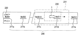
次にS225では、算出自車位置を中心とする所定範囲内の地図画像を表す地図データ、すなわちS220により認識された単位ラインが含まれた地図画像を表す地図データを、地図データベース51から取得する。なお、地図データが表す地図画像では、一例として図9に示すように、基準とする特徴道路標示220と、破線状の白線206を構成する単位ライン211(211a〜211e)のそれぞれに割り当てられた識別番号とが認識可能となっている。
Next, in S225, map data representing a map image within a predetermined range centered on the calculated vehicle position, that is, map data representing a map image including a unit line recognized in S220 is acquired from the
続くS230では、S215により認識された撮像画像における単位ラインと、S225で取得した地図データが表す地図画像に含まれる単位ラインとを対比し、撮像画像における単位ラインが、地図画像におけるどの単位ラインに対応するのかを、識別番号に基づいて特定する。これにより、地図画像における撮像画像の位置(撮像範囲)が特定され、その結果、地図画像において自車位置が特定される。 In subsequent S230, the unit line in the captured image recognized in S215 is compared with the unit line included in the map image represented by the map data acquired in S225, and the unit line in the captured image is the unit line in the map image. The correspondence is specified based on the identification number. Thereby, the position (imaging range) of the captured image in the map image is specified, and as a result, the vehicle position is specified in the map image.
ここで、前述の図9を用いて、破線状の白線206を用いた自車位置の特定について説明する。一例として、図9では、一点鎖線で示す撮像画像の撮像範囲230に一つの単位ライン211dが含まれているものとする。ここで、S225で取得した地図データが表す所定範囲231内の地図画像には、単位ライン211dを含む複数の単位ライン(単位ライン211c及び211d)が含まれているものとする。一方、撮像画像では、白線カウント情報(基準情報、識別番号)に基づいて、単位ライン211dが特徴道路標示220から11番目の単位ラインであることが認識されている。したがって、地図画像と撮像画像との対比によって、地図画像における撮像画像の位置(撮像範囲230)が特定され、地図画像において自車位置が特定される。
Here, the identification of the position of the vehicle using the broken
S235では、算出自車位置を、S230で特定した自車位置に置き換えることで、算出自車位置の補正(検出誤差のリセット)を行う。そして、本白線利用更新処理を終了する。 In S235, the calculated vehicle position is corrected (detection error reset) by replacing the calculated vehicle position with the vehicle position specified in S230. And this white line utilization update process is complete | finished.
次に、白線利用更新処理のS220で用いられる白線カウント情報を出力する白線カウント処理の一例について、図8に示すフローチャートを用いて説明する。白線カウント処理は、撮像画像に含まれる単位ラインが、基準とした特徴道路標示から何番目の単位ラインに相当するかを数える処理であり、自車位置算出処理と並行して、制御装置61により前述した撮像周期に合わせて実行されている。
Next, an example of the white line count process for outputting the white line count information used in S220 of the white line use update process will be described with reference to the flowchart shown in FIG. The white line counting process is a process of counting the unit line corresponding to the unit road included in the captured image from the characteristic road marking as a reference. In parallel with the vehicle position calculation process, the white line counting process is performed by the
S305では、撮像部20(カメラ21〜24)から出力される撮像情報を取得する。続くS310では、取得した撮像情報に基づいて、S110と同様に、自車両周辺の道路を鉛直方向に見下ろした撮像画像を生成する。次にS315では、S310で生成した撮像画像において、破線状の白線を構成する長方形の単位ラインの形状を、周知のパタンマッチングの手法により認識する。
In S305, the imaging information output from the imaging unit 20 (
続くS320では、S315の認識結果に基づいて、新たな単位ラインを検出したか否かを判定する。ここで、新たな単位ラインを検出していない場合はS330へ移行し、新たな単位ラインを検出した場合はS325へ移行する。S325では、いままでの識別番号に1を加えた値を新たな識別番号としてRAM64に記憶し、S330へ移行する。
In subsequent S320, it is determined whether or not a new unit line has been detected based on the recognition result in S315. If a new unit line is not detected, the process proceeds to S330. If a new unit line is detected, the process proceeds to S325. In S325, the value obtained by adding 1 to the previous identification number is stored in the
S330では、S310で生成した撮像画像において、基準とした特徴道路標示とは異なる新たな特徴道路標示が検出されたか否かを判定する。ここで、新たな特徴道路標示が検出されなかった場合は、本白線カウント処理を終了する。一方、新たな特徴道路標示が検出された場合は、S335に移行する。S335では、識別番号の値をリセットする(識別番号を0としてRAM64に記憶する)。続くS340では、新たに検出された特徴道路標示についての情報(特徴道路標示の種類、絶対位置(緯度、経度)等)を基準情報としてRAM64に記憶する。そして、本白線カウント処理を終了する。なお、RAM64に記憶されている基準情報及び識別番号が、前述の白線カウント情報に相当する。
In S330, it is determined whether or not a new characteristic road marking different from the reference characteristic road marking is detected in the captured image generated in S310. Here, when a new characteristic road marking is not detected, the white line counting process is terminated. On the other hand, when a new characteristic road marking is detected, the process proceeds to S335. In S335, the value of the identification number is reset (the identification number is set to 0 and stored in the RAM 64). In subsequent S340, information on the newly detected characteristic road marking (type of characteristic road marking, absolute position (latitude, longitude), etc.) is stored in the
つまり、制御装置61は、白線カウント処理によって、新たに検出された特徴道路標示を基準として、次に新たな特徴道路標示が検出されるまでの間、単位ラインごとに識別番号を割り当てRAM64に記憶する、という処理を繰り返し実行する。
That is, the
[2−4.対向車更新処理]
次に、リセット処理のS145で実行される対向車更新処理について、図10のフローチャートを用いて説明する。
[2-4. Oncoming vehicle update process]
Next, the oncoming vehicle update process executed in S145 of the reset process will be described with reference to the flowchart of FIG.
S405では、無線通信装置11によって、自車両1の周辺(電波の届く通信エリア内)に存在する対向車へ、自車両1についての走行データを無線送信する。走行データには、自車両1の算出自車位置P1、及び継続時間T1が含まれる。継続時間T1とは、算出自車位置P1の補正が最後に行われた後、自立航法による自車位置の算出が継続されている時間をいう。なお、本実施形態では、自車両1と同様の自車位置検出装置10が対向車にも搭載されていることが前提とされている。
In S <b> 405, the
続くS410では、無線通信装置11によって、対向車2から送信される当該対向車2についての走行データ(対向車2の算出自車位置P2、対向車2の継続時間T2)を受信したか否かを判定する。ここで、対向車2から走行データを受信しなかった場合、本対向車更新処理を終了する。一方、対向車2から走行データを受信した場合、S415へ移行する。
In subsequent S410, whether or not the
S415では、S150で取得した撮像情報に基づいて、S110と同様に、自車両周辺の道路を鉛直方向に見下ろした撮像画像を生成する。次にS420では、S415で生成した撮像画像において、対向車2を、周知のパタンマッチングの手法により認識する。
In S415, based on the imaging information acquired in S150, a captured image in which the road around the host vehicle is looked down in the vertical direction is generated as in S110. Next, in S420, the oncoming
続くS425では、撮像画像において、対向車2に対する自車両1の相対位置P3を算出する。次にS430では、S415で受信した対向車2の算出自車位置P2に、S430で算出した相対位置P3を加算して、対向車2の算出自車位置P2を基準とした自車位置P4を算出する。
In subsequent S425, the relative position P3 of the
続くS435では、自車両1の継続時間T1と対向車2の継続時間T2とを比較し、これらの差が所定の継続しきい値未満であるか否かを判定する。継続しきい値は、0に近い値に設定される。ここで、継続しきい値以上である場合はS445へ移行し、継続しきい値未満である場合はS440へ移行する。
In continuing S435, continuation time T1 of the
S440では、対向車2の算出自車位置P2を基準として算出した自車位置P4と自車両1の算出自車位置P1との平均値、つまり中間位置を算出する。そして、算出自車位置P1をS440で算出した中間位置に置き換えることで、算出自車位置P1の補正(検出誤差のリセット)を行う。そして、本対向車更新処理を終了する。
In S440, an average value of the own vehicle position P4 calculated based on the calculated own vehicle position P2 of the
S435で自車両1の継続時間T1と対向車2の継続時間T2との差が継続しきい値以上であると判定した場合に移行するS445では、対向車2の継続時間T2が自車両1の継続時間T1未満であるか否かを判定する。ここで、対向車2の継続時間T2が自車両1の継続時間T1未満である場合、S450へ移行する。S450では、自車両1の算出自車位置P1を、S430で対向車2の算出自車位置P2を基準として算出した自車位置P4に置き換えることで、算出自車位置P1の補正(検出誤差のリセット)を行う。そして、本対向車更新処理を終了する。
In S445, when the determination is made that the difference between the duration T1 of the
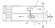
つまり、対向車更新処理では、一例として図11に示すように、自車両1の撮像範囲241に対向車2が認識されると(S420)、対向車2の算出自車位置P2を基準として算出した自車位置P4が算出される(S430)。そして、例えば、自車両1の継続時間T1よりも他車両2の継続時間T2が短い場合は(S445:YES)、自車両1の算出自車位置P1が、自立航法による誤差の蓄積が少ないと推定される自車位置P4に置き換えられる(S450)。
That is, in the oncoming vehicle update process, as shown in FIG. 11 as an example, when the
なお、図11において、一点鎖線242は、本来の自車両1の走行軌跡(真の走行軌跡)を示し、実線243は、算出自車位置P1に基づく走行軌跡を示している。すなわち、対向車2を利用して算出自車位置P1を補正する(置き換える)前は、算出自車位置P1に基づく実際の走行軌跡243には、真の走行軌跡242に対するずれが生じている。これに対し、対向車2を利用して算出自車位置P1を補正した(置き換えた)以降は、対向車2を利用した補正が行われないと仮定した場合の自車両1の走行軌跡(二点鎖線)244と比べると、自車両1の走行軌跡(実線242)について、真の走行軌跡(一点鎖線)242に対するずれが抑制される。
In FIG. 11, an alternate long and
また、本実施形態では、対向車2の撮像範囲245に自車両1が認識されると、対向車2では、自車両1と同様の処理が行われる。すなわち、対向車2においても同様に、自車両1を利用した算出自車位置P2の補正(置き換え)以降は、自車両1を利用した補正が行われないと仮定した場合の対向車2の走行軌跡(二点鎖線)246と比べると、対向車2の算出自車位置P2に基づく走行軌跡(実線247)について、対向車2の真の走行軌跡(一点鎖線)248に対するずれが抑制される。
In the present embodiment, when the
[3.効果]
以上詳述した第1実施形態によれば、以下の効果が得られる。
[3A]第1実施形態では、撮像画像において道路標示(特徴道路標示)が認識された場合は、撮像画像における特徴道路標示の形状と、地図データが表す地図画像に含まれる特徴道路標示の形状とを対比して、自車両1の算出自車位置P1の補正を行う。すなわち、撮像画像における自車両1の位置は一定であるため、地図画像と撮像画像との対比によって地図画像における撮像画像の位置(撮像範囲)が特定され、その結果、地図画像において算出自車位置P1が特定される(S125)。そして、算出自車位置P1を、S125で特定した自車位置に置き換えることで、算出自車位置P1の補正(検出誤差のリセット)を行う(S130)。このような構成によれば、地図画像と撮像画像との対比に基づいて算出自車位置P1の特定(補正)を行うため、GPSの測位信号に基づいて自車位置を検出する場合と比べて、自車位置を精度よく検出することができる。
[3. effect]
According to the first embodiment described in detail above, the following effects can be obtained.
[3A] In the first embodiment, when a road marking (characteristic road marking) is recognized in the captured image, the shape of the characteristic road marking in the captured image and the shape of the characteristic road marking included in the map image represented by the map data And the calculated own vehicle position P1 of the
[3B]第1実施形態では、撮像画像において、特徴道路標示が認識されず、破線状の白線が認識された場合は、撮像画像における破線状の白線を構成する単位ラインが、地図画像におけるどの単位ラインに対応するのかを、白線カウント処理で検出した識別番号に基づいて特定する(S230)。このような構成によれば、撮像画像において破線状の白線が写っている場合、すなわち、同じ形状をしている単位ラインが連続して複数写っている場合であっても、単位ラインのそれぞれを識別番号に基づいて識別することができるため、地図画像と撮像画像との対比によって、地図画像における自車両1の算出自車位置P1を特定することができる。
[3B] In the first embodiment, when a feature road marking is not recognized in the captured image and a broken white line is recognized, the unit lines constituting the broken white line in the captured image indicate which unit line in the map image Whether it corresponds to a unit line is specified based on the identification number detected by the white line counting process (S230). According to such a configuration, even when a broken white line is captured in the captured image, that is, when a plurality of unit lines having the same shape are continuously captured, each unit line is Since it can identify based on an identification number, the calculation own vehicle position P1 of the
[3C]第1実施形態では、撮像画像において、特徴道路標示、及び破線状の白線が認識されなかった場合、撮像情報が表す画像において対向車2が検出された場合は、対向車2から取得した当該対向車2の算出自車位置P2と継続時間T2とを用いて、自車両1の算出自車位置P1の補正を行う。具体的には、対向車2の算出自車位置P2と、撮像画像に基づき算出された自車両1に対する対向車2の相対位置P3とに基づいて、自車位置P4を特定する(S435)。
[3C] In the first embodiment, when a feature road marking and a dashed white line are not recognized in the captured image, or when the
そして、対向車2における継続時間T2が自車両1における継続時間T1よりも短いことを条件として、自立航法に基づく算出自車位置P1に対する補正後の算出自車位置の距離と比較して、対向車2の算出自車位置P2とS425により算出された相対位置P3とに基づく自車位置P4に対する補正後の算出自車位置の距離が短くなるように、算出自車位置P1を補正する(S445〜S450)。このような構成によれば、自立航法の継続時間が短い対向車2の算出自車位置P2を基準として算出した自車位置P4に近い位置に算出自車位置P1が補正されるため、自車位置を精度よく検出することができる。特に第1実施形態のS445〜S450では、算出自車位置P1を、対向車2の算出自車位置P2を基準として算出した自車位置P4に置き換える補正を行っている。すなわち、置き換えという簡易な構成により、自車位置の補正が実現されている。
Then, on the condition that the duration T2 in the
[3D]また、第1実施形態では、対向車2における継続時間T2と自車両1における継続時間T1との差が継続しきい値未満であることを条件として、自立航法基づく算出自車位置P1と、S430で算出された自車位置P4との中間となる位置に、算出自車位置P1を置き換える補正を行っている(S435〜S440)。これにより、自車両1の自立航法の継続時間T1と対向車2の自立航法の継続時間T2とがほぼ同じ値である場合は、自立航法の継続による検出誤差が抑制されるように、算出自車位置P1を補正することができる。結果として、自車位置を精度よく検出することができる。
[3D] Further, in the first embodiment, the calculated host vehicle position P1 based on the self-contained navigation is provided on the condition that the difference between the duration T2 in the
[3E]第1実施形態では、GPS受信困難エリアに侵入する前に、自立航法に基づく算出自車位置を補正するため、仮にGPS受信困難エリア内でGPSリセットを実行できなかったとしても、自立航法による検出誤差を抑制することができる。 [3E] In the first embodiment, since the calculated vehicle position based on the self-contained navigation is corrected before entering the GPS reception difficulty area, even if GPS reset cannot be executed in the GPS reception difficulty area, it is independent. Detection errors due to navigation can be suppressed.
[3F]第1実施形態では、GPS受信困難エリアを走行中であっても、GPS受信困難エリアで道路標示を検出可能であれば、自車位置を精度よく検出できる。このため、GPS受信困難エリアから抜け出してGPS用の人工衛星からの測位信号を受信できるエリアに侵入した際に、いわゆるGPSコールドスタート時間(GPS用の人工衛星の現在状態について正確な情報の無い状態から、GPS用の人工衛星からの測位信号を用いて自車位置を検出するために要する時間)を短縮することができる。 [3F] In the first embodiment, even if the vehicle is traveling in a GPS reception difficulty area, the vehicle position can be detected with high accuracy if a road marking can be detected in the GPS reception difficulty area. For this reason, when entering the area where the positioning signal from the GPS artificial satellite can be received by exiting the GPS reception difficult area, the so-called GPS cold start time (the state where there is no accurate information on the current state of the GPS artificial satellite) Therefore, the time required to detect the position of the vehicle using the positioning signal from the GPS satellite can be shortened.
なお、第1実施形態では、カメラ21〜24が「撮像装置」の一例に相当し、ジャイロスコープ41、車速センサ42、及びGセンサ43が「自立センサ」の一例に相当する。また、S105〜S110、S205〜S210、S305〜S310の処理が「画像生成手段」としての処理の一例に相当し、S115、S215、S315の処理が「標示認識手段」としての処理の一例に相当する。また、S120、S225の処理が「地図データ取得手段」としての一例に相当し、S125〜S130、S230〜S235の処理が「位置補正手段」としての一例に相当する。また、S320〜S335の処理が「カウント手段」としての一例に相当する。また、S150〜S155の処理が「他車両認識手段」としての処理の一例に相当し、S410の処理が「他車位置取得手段」としての処理の一例に相当し、S415〜S425の処理が「相対位置算出手段」としての処理の一例に相当する。また、S435〜S450の処理が「他車利用補正手段」としての処理の一例に相当し、S10の処理が「位置更新手段」としての処理の一例に相当し、S410の処理が「継続時間取得手段」としての処理の一例に相当し、S430の処理が「自車位置算出手段」としての処理の一例に相当する。
In the first embodiment, the
[4.他の実施形態]
以上、本発明の実施形態について説明したが、本発明は、上記実施形態に限定されることなく、種々の形態を採り得ることは言うまでもない。
[4. Other Embodiments]
As mentioned above, although embodiment of this invention was described, it cannot be overemphasized that this invention can take a various form, without being limited to the said embodiment.
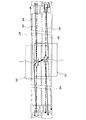
[4A]上記実施形態では、撮像画像における自車両1の位置は一定であり、撮像画像における道路標示と地図画像における道路標示との対比によって、地図画像における自車位置が特定されていた。これに対し、次に図12を用いて説明するように、道路標示の形状を利用して地図画像における自車位置を特定してもよい。
[4A] In the above embodiment, the position of the
前述のように、地図データベース51に記憶されている地図データが表す地図には、道路標示(位置及び形状)が詳細に(正確に)示されているため、地図データが表す地図の縮尺と地図データが表す地図における道路標示の寸法とから、実際の道路標示の寸法が算出される。すなわち、撮像画像と地図画像との対比によって地図画像における撮像画像の位置(撮像範囲)が特定された後に、撮像画像における道路標示の寸法と当該道路標示に対する自車両1の位置とに基づいて、算出自車位置P1を求めることができる。
As described above, the map represented by the map data stored in the
具体的には、まず、図12に示す自車両1の進行方向前方右側の車両基準点B1の絶対座標を算出する。ここでは、一例として、横断歩道201の停止線202の長さをK1とし、幅をK3とし、自車両1の進行方向における停止線202から車両基準点B1までの距離を進行方向距離Tとし、道路の幅方向における中央線(白線)207から車両基準点B1までの幅方向距離をSとする。すなわち、停止線202の幅K3に対する進行方向距離T、及び停止線202の長さK1に対する幅方向距離Sの比例関係と、地図データが表す地図から算出される停止線202の長さK1及び幅K3の実際の長さとから、進行方向距離T及び幅方向距離Sの実際の長さが算出される。そして、停止線202の幅方向右側の道路標示基準点A1の絶対位置は地図データが表す地図から明らかであるため、算出した進行方向距離T及び幅方向距離Sの実際の長さに基づいて、車両基準点B1の絶対位置が算出される。
Specifically, first, absolute coordinates of a vehicle reference point B1 on the front right side in the traveling direction of the
自車両1の中央位置を算出自車位置P1とし、自車両1の長手方向の長さSH、及び幅SWの長さについての実際の値が予め地図データベース51に記憶されているとすると、算出自車位置P1は、図12に示すように、車両基準点B1から自車両1の進行方向にSH/2、及び幅方向にSW/2ずれた位置として求められる。
The center position of the
なお、ここでは、停止線202を算出自車位置P1を求めるための基準とする道路標示として用いたが、算出自車位置P1を求めるために基準として用いる道路標示は、これに限るものではない。この他に、例えば、横断歩道201の幅K2及び長さK4、中央線207の幅F等のように、撮像画像における道路標示の各部の長さに基づいて、算出自車位置P1を求めてもよい。
Here, the
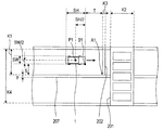
[4B]上記実施形態の対向車更新処理では、S150で取得した撮像情報に基づく撮像画像を用いて、自車両1の算出自車位置P1を特定していた。これに対し、例えば、図10に示すS440の後に、S150及びS415と同様の処理を追加して撮像情報を取得して当該撮像情報に基づく撮像画像を生成し、さらに生成した撮像画像において道路の幅方向における自車位置を算出する処理を追加して、算出自車位置P1を特定してもよい。算出自車位置P1の特定は、第1実施形態と同様に、地図画像と撮像画像との対比によって地図画像における自車位置を特定するようにしてもよい。または、他の実施形態[4A]と同様に、例えば図13に示す撮像画像における道路幅RW、中央線208の幅E、及び道路の端を示す区画線209の幅F等に基づいて、自車両1の進行方向後方左側の車両基準点C1から算出自車位置P1を算出するようにしてもよい。これにより、算出自車位置P1の道路の幅方向成分については、図5のS150で取得した撮像情報と比べて、直近に取得した撮像情報に基づく撮像画像から算出されるため、より正確に算出自車位置P1の補正を行うことができる。
[4B] In the oncoming vehicle update process of the above embodiment, the calculated host vehicle position P1 of the
[4C]上記実施形態では、破線状の白線として、道路の中央に描画されている区画線(例えば図6に示す破線状の白線203)や、複数の車線の境界を示す区画線(例えば図7に示す破線状の白線206)が一例として挙げられていたが、破線状の白線は、これらに限るものではない。例えば、破線状の白線は、路側帯を示す区画線の一部(駐停車禁止路側帯に含まれる破線状の白線)等であってもよい。また、単位ラインの形状は、破線状の白線の種類に従って定められている形状であればよい。
[4C] In the above-described embodiment, a lane marking drawn at the center of the road (for example, the dashed
[4D]上記実施形態では、自車位置算出処理において、撮像画像において道路標示(特徴道路標示及び破線状の白線)及び対向車2が認識されない場合はGPSリセットが実行されていたが、自車位置算出処理においてGPSリセットが実行されない構成であってもよい。また、自車位置算出処理において、破線状の白線を用いて自車両1の算出自車位置P1の補正を行う処理や、対向車リセットが実行されない構成であってもよい。
[4D] In the above embodiment, in the vehicle position calculation process, when the road marking (characteristic road marking and broken white line) and the
[4E]上記実施形態では、撮像部20は4つのカメラ21〜24を備えていたが、カメラの数はこれに限らない。例えば、撮像部20は、前方カメラ21及び後方カメラ22の2台を備えるように構成されてもよい。または、撮像部20は、前方カメラ21を1台備える構成、あるいは後方カメラ22を1台備える構成であってもよい。また、撮像部20が備えるカメラは、鉛直方向真上から道路を撮像するように、車両1に設置されていてもよい。
[4E] In the above embodiment, the
[4F]上記実施形態では、自車両1が自立航法に基づく算出自車位置P1(P)から道なりに進むと仮定した場合に、GPS受信困難エリアに自車両1が侵入するまでの距離が所定距離未満となった場合に、GPSリセットが実行されていた。これに対し、例えば、自車位置検出装置10を用いたナビゲーション装置において現在位置から目的地までのルートが設定されており、当該ルート上にGPS受信困難エリアが存在する場合のように、GPS受信困難エリアを通過することが確実である場合に、GPSリセットが実行されてもよい。
[4F] In the above embodiment, when it is assumed that the
[4G]上記形態のS445〜S450では、一例として、対向車2の算出自車位置P2を基準として算出した自車位置P4に、自車両1の算出自車位置P1が補正される例が示されていたが、これに限るものではない。例えば、自車両1の継続時間T1と対向車2の継続時間T2とを比較して、継続時間T2及び継続時間T1の大きさに応じて重み付けを行い、継続時間が短い対向車2の算出自車位置P2を基準として算出した自車位置P4により近い位置に、補正後の算出自車位置P1を定めるようにしてもよい。
[4G] In S445 to S450 of the above embodiment, as an example, an example in which the calculated vehicle position P1 of the
[4H]上記実施形態では、対向車更新処理において、対向車2の走行データを利用して自車両1の算出自車位置P1の補正を実行していたが、これに限るものではない。例えば、走行方向が自車両1の走行方向と同じ他車両の走行データを利用して、算出自車位置P1の補正を実行してもよい。
[4H] In the above embodiment, in the oncoming vehicle update process, the travel data of the
[4I]上記実施形態では、地図画像を表す地図データを、車両1に搭載された自車位置検出装置10の地図データベース51から取得していたが、本実施形態に用いられる地図データはこれに限るものではない。例えば、本実施形態に用いられる地図データは、クラウド経由で取得された地図データであってもよい。また例えば、本実施形態に用いられる地図データは、地域の道路管理局等のローカルサーバから取得した道路封鎖状況が反映された地図を表す地図データや、観光局等のローカルサーバから取得した催事(例えば祭事による通行止め等)の状況が反映された地図を表す地図データ等であってもよい。
[4I] In the above embodiment, the map data representing the map image is acquired from the
[4J]上記実施形態では、地図データの表す地図画像には道路標示の形状が詳細に示されていたが、これに限らず、正確な道路形状(道路幅、道路の前後の傾き及び幅方向の傾き、砂利道であるか舗装道路であるか等の整備状態等を含む)が示されていてもよい。また、地図データが表す地図画像には、道路標識、道路に設けられている看板、道路近くの建築物等のような、道路周辺の構造物の形状(及び位置)が詳細に示されていてもよい。このような地図データを用いれば、撮像画像におけるこれらの道路形状や道路周辺の構造物の形状と、地図画像におけるこれらの形状とを対比させて、上記実施形態と同様に、自車位置を精度よく検出することができる。 [4J] In the above embodiment, the shape of the road marking is shown in detail in the map image represented by the map data. However, the present invention is not limited to this, and the accurate road shape (the road width, the inclination before and after the road, and the width direction) is shown. And the state of maintenance such as whether it is a gravel road or a paved road). In addition, the map image represented by the map data shows in detail the shape (and position) of structures around the road, such as road signs, signs on the road, and buildings near the road. Also good. If such map data is used, the shape of the road in the captured image or the shape of the structure around the road is compared with the shape in the map image, and the vehicle position can be accurately determined as in the above embodiment. Can be detected well.
[4K]上記実施形態では、前回のリセットから所定のリセット期間が経過している場合に、リセット周期であると判定していたが、前回のリセットが行われたときの自車位置から所定のリセット距離を走行している場合に、リセット周期であると判定してもよい。 [4K] In the above embodiment, when a predetermined reset period has elapsed since the previous reset, it is determined that the reset cycle has occurred, but the predetermined position is determined based on the vehicle position when the previous reset is performed. When traveling the reset distance, it may be determined that it is a reset cycle.
[4L]上記実施形態における1つの構成要素が有する機能を複数の構成要素として分散させたり、複数の構成要素が有する機能を1つの構成要素に統合したりしてもよい。また、上記実施形態の構成の少なくとも一部を、同様の機能を有する公知の構成に置き換えてもよい。また、上記実施形態の構成の一部を、課題を解決できる限りにおいて省略してもよい。また、上記実施形態の構成の少なくとも一部を、他の上記実施形態の構成に対して付加、置換等してもよい。なお、特許請求の範囲に記載の文言から特定される技術思想に含まれるあらゆる態様が本発明の実施形態である。 [4L] The functions of one component in the above embodiment may be distributed as a plurality of components, or the functions of a plurality of components may be integrated into one component. Further, at least a part of the configuration of the above embodiment may be replaced with a known configuration having the same function. Moreover, you may abbreviate | omit a part of structure of the said embodiment as long as a subject can be solved. In addition, at least a part of the configuration of the above embodiment may be added to or replaced with the configuration of the other embodiment. In addition, all the aspects included in the technical idea specified from the wording described in the claims are embodiments of the present invention.
[4M]本発明は、前述した自車位置検出装置10の他、当該自車位置検出装置10を構成する制御装置、当該制御装置としてコンピュータを機能させるためのプログラム、このプログラムを記録した媒体、自車位置算出方法など、種々の形態で実現することができる。
[4M] The present invention includes, in addition to the above-described own vehicle
1…車両(自車両) 2…他車両(対向車) 10…自車位置検出装置 11…無線通信装置 20…撮像部 21…前方カメラ 22…後方カメラ 23…右側方カメラ 24…左側方カメラ 40…位置検出部 41…ジャイロスコープ 42…車速センサ 43…Gセンサ 51…地図データベース 61…制御装置 62…CPU 63…ROM 64…RAM。
DESCRIPTION OF
Claims (5)
自車両に取り付けられた撮像装置(21〜24)からの撮像情報に基づいて、自車両周辺の道路を鉛直方向に見下ろした撮像画像を生成する画像生成手段(S105〜S110、S205〜S210、S305〜S310)と、
前記撮像画像において、道路に描画された道路標示の形状を認識する標示認識手段(S115、S215、S315)と、
前記道路標示の形状が含まれた地図画像を表す地図データを取得する地図データ取得手段(S120、S225)と、
前記標示認識手段により認識された前記道路標示の形状と、前記地図画像に含まれる前記道路標示であって自車両周辺に存在する前記道路標示の形状と、を対比して自車両の絶対位置を補正する位置補正手段(S125〜S130、S230〜S235)と、
を備えることを特徴とする自車位置検出装置。 A vehicle position detection device (10) used in a vehicle,
Based on the imaging information from the imaging devices (21 to 24) attached to the host vehicle, image generation means (S105 to S110, S205 to S210, S305) that generates a captured image looking down the road around the host vehicle in the vertical direction. To S310),
In the captured image, sign recognition means (S115, S215, S315) for recognizing the shape of the road sign drawn on the road;
Map data acquisition means (S120, S225) for acquiring map data representing a map image including the shape of the road marking;
The absolute position of the host vehicle is determined by comparing the shape of the road sign recognized by the sign recognition means with the shape of the road sign included in the map image and existing around the host vehicle. Position correcting means (S125 to S130, S230 to S235) for correcting,
A vehicle position detection device comprising:
複数の単位ラインにより構成される破線状のラインが前記道路標示として前記標示認識手段により認識された場合に、他の前記道路標示の位置を基準とした識別番号を前記単位ラインごとに割り当てるカウント手段(S320〜S335)と、
を備え、
前記位置補正手段(S230)は、前記標示認識手段により認識された前記道路標示が前記単位ラインである場合に、前記地図画像に含まれる前記道路標示であって自車両周辺に存在する前記道路標示の中から、当該単位ラインに対応する前記道路標示を前記識別番号に基づいて特定すること、
を特徴とする自車位置検出装置。 The vehicle position detection device according to claim 1,
Counting means for assigning, for each unit line, an identification number based on the position of the other road marking when a broken line composed of a plurality of unit lines is recognized as the road marking by the marking recognition means. (S320 to S335),
With
The position correcting means (S230) is the road sign included in the map image and present around the host vehicle when the road sign recognized by the sign recognition means is the unit line. Identifying the road marking corresponding to the unit line based on the identification number,
A vehicle position detection device characterized by the above.
自車両周辺に存在する他車両を前記撮像情報に基づいて認識する他車両認識手段(S150〜S155)と、
前記他車両認識手段により認識された前記他車両から、当該他車両の絶対位置を無線通信により取得する他車位置取得手段(S410)と、
前記他車両が認識された前記撮像画像に基づいて、自車両に対する前記他車両の相対位置を算出する相対位置算出手段(S415〜S425)と、
前記他車位置取得手段により取得された前記他車両の絶対位置と、前記相対位置算出手段により算出された前記相対位置とに基づいて、自車両の絶対位置を補正する他車利用補正手段(S435〜S450)と、
を備えることを特徴とする自車位置検出装置。 It is the own vehicle position detection device according to claim 1 or 2,
Other vehicle recognition means (S150 to S155) for recognizing other vehicles existing around the own vehicle based on the imaging information;
Other vehicle position acquisition means (S410) for acquiring the absolute position of the other vehicle from the other vehicle recognized by the other vehicle recognition means by wireless communication;
Relative position calculation means (S415 to S425) for calculating the relative position of the other vehicle with respect to the host vehicle based on the captured image in which the other vehicle is recognized;
Other vehicle use correcting means (S435) for correcting the absolute position of the own vehicle based on the absolute position of the other vehicle acquired by the other vehicle position acquiring means and the relative position calculated by the relative position calculating means. To S450),
A vehicle position detection device comprising:
自車両の挙動変化を検出する自立センサ(41、42、43)の出力値に基づいて自車両の絶対位置を更新する位置更新手段(S10)と、
前記他車両において前記自立センサの出力値に基づいて当該他車両の絶対位置が更新されている継続時間を、当該他車両から無線通信により取得する継続時間取得手段(S410)と、
前記他車位置取得手段により取得された前記他車両の絶対位置と、前記相対位置算出手段により算出された前記相対位置とに基づいて、自車両の絶対位置を算出する自車位置算出手段(S430)と、
を備え、
前記他車利用補正手段(S445〜S450)は、前記継続時間取得手段により取得された前記他車両における前記継続時間が、自車両における前記継続時間よりも短いことを条件として、前記位置更新手段により更新された自車両の絶対位置に対する補正後の自車両の絶対位置の距離と比較して、前記自車位置算出手段により算出された自車両の絶対位置に対する補正後の自車両の絶対位置の距離が短くなるように、自車両の現在位置を補正すること、
を特徴とする自車位置検出装置。 The own vehicle position detection device according to claim 3,
Position updating means (S10) for updating the absolute position of the own vehicle based on the output value of the self-supporting sensor (41, 42, 43) for detecting the behavior change of the own vehicle;
A duration acquisition means (S410) for acquiring, from the other vehicle by wireless communication, a duration in which the absolute position of the other vehicle is updated based on the output value of the self-supporting sensor in the other vehicle;
Own vehicle position calculating means (S430) for calculating the absolute position of the own vehicle based on the absolute position of the other vehicle acquired by the other vehicle position acquiring means and the relative position calculated by the relative position calculating means. )When,
With
The other vehicle use correcting means (S445 to S450) is provided by the position updating means on condition that the duration time in the other vehicle acquired by the duration acquisition means is shorter than the duration time in the own vehicle. Compared with the corrected absolute position distance of the own vehicle with respect to the updated absolute position of the own vehicle, the corrected absolute position distance of the own vehicle with respect to the absolute position of the own vehicle calculated by the own vehicle position calculating means To correct the current position of the vehicle so that
A vehicle position detection device characterized by the above.
自車両の挙動変化を検出する自立センサ(41、42、43)の出力値に基づいて自車両の絶対位置を更新する位置更新手段(S10)と、
前記他車両において前記自立センサの出力値に基づいて当該他車両の絶対位置が更新されている継続時間を、当該他車両から無線通信により取得する継続時間取得手段(S410)と、
前記他車位置取得手段により取得された前記他車両の絶対位置と、前記相対位置算出手段により算出された前記相対位置とに基づいて、自車両の絶対位置を算出する自車位置算出手段(S430)と、
を備え、
前記他車利用補正手段(S435〜S440)は、前記継続時間取得手段により取得された前記他車両における前記継続時間と、自車両における前記継続時間との差が所定のしきい値未満であることを条件として、前記位置更新手段により更新された自車両の絶対位置と前記自車位置算出手段により算出された自車両の絶対位置との中間となる位置に、自車両の絶対位置を補正すること、
を特徴とする自車位置検出装置。 The own vehicle position detection device according to claim 3,
Position updating means (S10) for updating the absolute position of the own vehicle based on the output value of the self-supporting sensor (41, 42, 43) for detecting the behavior change of the own vehicle;
A duration acquisition means (S410) for acquiring, from the other vehicle by wireless communication, a duration in which the absolute position of the other vehicle is updated based on the output value of the self-supporting sensor in the other vehicle;
Own vehicle position calculating means (S430) for calculating the absolute position of the own vehicle based on the absolute position of the other vehicle acquired by the other vehicle position acquiring means and the relative position calculated by the relative position calculating means. )When,
With
The other vehicle use correction means (S435 to S440) is such that a difference between the duration time in the other vehicle acquired by the duration time acquisition means and the duration time in the own vehicle is less than a predetermined threshold value. The absolute position of the host vehicle is corrected to a position intermediate between the absolute position of the host vehicle updated by the position update unit and the absolute position of the host vehicle calculated by the host vehicle position calculation unit. ,
A vehicle position detection device characterized by the above.
Priority Applications (2)
| Application Number | Priority Date | Filing Date | Title |
|---|---|---|---|
| JP2013254217A JP2015114126A (en) | 2013-12-09 | 2013-12-09 | Vehicle location detection device |
| PCT/JP2014/005900 WO2015087502A1 (en) | 2013-12-09 | 2014-11-26 | Vehicle self-location device |
Applications Claiming Priority (1)
| Application Number | Priority Date | Filing Date | Title |
|---|---|---|---|
| JP2013254217A JP2015114126A (en) | 2013-12-09 | 2013-12-09 | Vehicle location detection device |
Publications (1)
| Publication Number | Publication Date |
|---|---|
| JP2015114126A true JP2015114126A (en) | 2015-06-22 |
Family
ID=53370833
Family Applications (1)
| Application Number | Title | Priority Date | Filing Date |
|---|---|---|---|
| JP2013254217A Pending JP2015114126A (en) | 2013-12-09 | 2013-12-09 | Vehicle location detection device |
Country Status (2)
| Country | Link |
|---|---|
| JP (1) | JP2015114126A (en) |
| WO (1) | WO2015087502A1 (en) |
Cited By (16)
| Publication number | Priority date | Publication date | Assignee | Title |
|---|---|---|---|---|
| WO2017057044A1 (en) * | 2015-09-30 | 2017-04-06 | ソニー株式会社 | Information processing device and information processing method |
| JP2017078607A (en) * | 2015-10-19 | 2017-04-27 | 株式会社豊田中央研究所 | Vehicle position estimation device and program |
| JP2017146293A (en) * | 2016-02-18 | 2017-08-24 | トヨタ自動車株式会社 | Vehicle position estimation device |
| KR20170127665A (en) * | 2016-05-12 | 2017-11-22 | 현대모비스 주식회사 | System for estimating a vehicle location and method for estimating the vehicle location using the system |
| US10024668B2 (en) | 2016-08-18 | 2018-07-17 | Toyota Jidosha Kabushiki Kaisha | Position estimation system, position estimation method and mobile unit |
| JP2018141716A (en) * | 2017-02-28 | 2018-09-13 | パイオニア株式会社 | Position estimation apparatus, control method, and program |
| WO2018212283A1 (en) * | 2017-05-19 | 2018-11-22 | パイオニア株式会社 | Measurement device, measurement method and program |
| JP2019007790A (en) * | 2017-06-22 | 2019-01-17 | 本田技研工業株式会社 | Vehicle position determination device |
| CN109421712A (en) * | 2017-08-30 | 2019-03-05 | 本田技研工业株式会社 | Controller of vehicle, vehicle, control method for vehicle and storage medium |
| JP2019043246A (en) * | 2017-08-30 | 2019-03-22 | 本田技研工業株式会社 | Vehicle control device, vehicle, vehicle control method, and program |
| WO2019155569A1 (en) * | 2018-02-08 | 2019-08-15 | 三菱電機株式会社 | Obstacle detection device and obstacle detection method |
| KR102083571B1 (en) * | 2018-12-18 | 2020-03-02 | 박주환 | Method for analyzing location of vehicle and navigation device |
| WO2020053614A1 (en) | 2018-09-11 | 2020-03-19 | 日産自動車株式会社 | Driving assistance method and driving assistance device |
| JP2020056740A (en) * | 2018-10-04 | 2020-04-09 | 三菱電機株式会社 | Position correction system, on-vehicle unit, position correction method, and position correction program |
| CN112384820A (en) * | 2018-07-10 | 2021-02-19 | 罗伯特·博世有限公司 | Method and device for determining the position of a vehicle |
| JP2023532729A (en) * | 2020-06-30 | 2023-07-31 | ロベルト・ボッシュ・ゲゼルシャフト・ミト・ベシュレンクテル・ハフツング | Determining the starting position of the vehicle for localization |
Families Citing this family (3)
| Publication number | Priority date | Publication date | Assignee | Title |
|---|---|---|---|---|
| CN105718860B (en) * | 2016-01-15 | 2019-09-10 | 武汉光庭科技有限公司 | Localization method and system based on driving safety map and binocular Traffic Sign Recognition |
| FR3080448A1 (en) * | 2018-04-20 | 2019-10-25 | Psa Automobiles Sa | DEVICE AND METHOD FOR ANALYZING THE POSITION OF A VEHICLE BY COMPARISON OF DETERMINED AND KNOWN ENVIRONMENTAL INFORMATION |
| CN110554702B (en) * | 2019-09-30 | 2022-08-30 | 重庆元韩汽车技术设计研究院有限公司 | Unmanned automobile based on inertial navigation |
Citations (4)
| Publication number | Priority date | Publication date | Assignee | Title |
|---|---|---|---|---|
| JP2006153565A (en) * | 2004-11-26 | 2006-06-15 | Nissan Motor Co Ltd | Car-mounted navigation device and vehicle position correction method |
| JP2007153031A (en) * | 2005-12-01 | 2007-06-21 | Aisin Aw Co Ltd | Vehicle position calculation method and onboard device |
| JP2007178271A (en) * | 2005-12-28 | 2007-07-12 | Aisin Aw Co Ltd | Own position recognition system |
| JP2013050412A (en) * | 2011-08-31 | 2013-03-14 | Aisin Aw Co Ltd | Vehicle itself position recognition system, vehicle itself position recognition program, and vehicle itself position recognition method |
-
2013
- 2013-12-09 JP JP2013254217A patent/JP2015114126A/en active Pending
-
2014
- 2014-11-26 WO PCT/JP2014/005900 patent/WO2015087502A1/en not_active Ceased
Patent Citations (4)
| Publication number | Priority date | Publication date | Assignee | Title |
|---|---|---|---|---|
| JP2006153565A (en) * | 2004-11-26 | 2006-06-15 | Nissan Motor Co Ltd | Car-mounted navigation device and vehicle position correction method |
| JP2007153031A (en) * | 2005-12-01 | 2007-06-21 | Aisin Aw Co Ltd | Vehicle position calculation method and onboard device |
| JP2007178271A (en) * | 2005-12-28 | 2007-07-12 | Aisin Aw Co Ltd | Own position recognition system |
| JP2013050412A (en) * | 2011-08-31 | 2013-03-14 | Aisin Aw Co Ltd | Vehicle itself position recognition system, vehicle itself position recognition program, and vehicle itself position recognition method |
Cited By (35)
| Publication number | Priority date | Publication date | Assignee | Title |
|---|---|---|---|---|
| WO2017057044A1 (en) * | 2015-09-30 | 2017-04-06 | ソニー株式会社 | Information processing device and information processing method |
| US10753757B2 (en) | 2015-09-30 | 2020-08-25 | Sony Corporation | Information processing apparatus and information processing method |
| EP3358550A4 (en) * | 2015-09-30 | 2019-06-12 | Sony Corporation | INFORMATION PROCESSING DEVICE AND INFORMATION PROCESSING METHOD |
| JP2017078607A (en) * | 2015-10-19 | 2017-04-27 | 株式会社豊田中央研究所 | Vehicle position estimation device and program |
| JP2017146293A (en) * | 2016-02-18 | 2017-08-24 | トヨタ自動車株式会社 | Vehicle position estimation device |
| KR102552712B1 (en) * | 2016-05-12 | 2023-07-06 | 현대모비스 주식회사 | System for estimating a vehicle location and method for estimating the vehicle location using the system |
| KR20170127665A (en) * | 2016-05-12 | 2017-11-22 | 현대모비스 주식회사 | System for estimating a vehicle location and method for estimating the vehicle location using the system |
| US10024668B2 (en) | 2016-08-18 | 2018-07-17 | Toyota Jidosha Kabushiki Kaisha | Position estimation system, position estimation method and mobile unit |
| JP2018141716A (en) * | 2017-02-28 | 2018-09-13 | パイオニア株式会社 | Position estimation apparatus, control method, and program |
| WO2018212283A1 (en) * | 2017-05-19 | 2018-11-22 | パイオニア株式会社 | Measurement device, measurement method and program |
| US12044778B2 (en) | 2017-05-19 | 2024-07-23 | Pioneer Corporation | Measurement device, measurement method and program |
| JPWO2018212283A1 (en) * | 2017-05-19 | 2020-03-19 | パイオニア株式会社 | Measuring device, measuring method and program |
| JP2019007790A (en) * | 2017-06-22 | 2019-01-17 | 本田技研工業株式会社 | Vehicle position determination device |
| CN109421712B (en) * | 2017-08-30 | 2021-12-14 | 本田技研工业株式会社 | Vehicle control device, vehicle, vehicle control method, and storage medium |
| US10803307B2 (en) | 2017-08-30 | 2020-10-13 | Honda Motor Co., Ltd | Vehicle control apparatus, vehicle, vehicle control method, and storage medium |
| CN109421712A (en) * | 2017-08-30 | 2019-03-05 | 本田技研工业株式会社 | Controller of vehicle, vehicle, control method for vehicle and storage medium |
| JP2019043246A (en) * | 2017-08-30 | 2019-03-22 | 本田技研工業株式会社 | Vehicle control device, vehicle, vehicle control method, and program |
| JP2019043245A (en) * | 2017-08-30 | 2019-03-22 | 本田技研工業株式会社 | Vehicle control device, vehicle, vehicle control method and program |
| JPWO2019155569A1 (en) * | 2018-02-08 | 2020-09-24 | 三菱電機株式会社 | Obstacle detection device and obstacle detection method |
| US11845482B2 (en) | 2018-02-08 | 2023-12-19 | Mitsubishi Electric Corporation | Obstacle detection device and obstacle detection method |
| WO2019155569A1 (en) * | 2018-02-08 | 2019-08-15 | 三菱電機株式会社 | Obstacle detection device and obstacle detection method |
| CN112384820A (en) * | 2018-07-10 | 2021-02-19 | 罗伯特·博世有限公司 | Method and device for determining the position of a vehicle |
| US12047853B2 (en) | 2018-07-10 | 2024-07-23 | Robert Bosch Gmbh | Method and device for determining a position of a vehicle |
| CN112384820B (en) * | 2018-07-10 | 2024-05-24 | 罗伯特·博世有限公司 | Method and apparatus for determining vehicle position |
| JPWO2020053614A1 (en) * | 2018-09-11 | 2021-08-30 | 日産自動車株式会社 | Driving support method and driving support device |
| RU2760714C1 (en) * | 2018-09-11 | 2021-11-29 | Ниссан Мотор Ко., Лтд. | Driving assistance method and driving assistance device |
| JP7004080B2 (en) | 2018-09-11 | 2022-01-24 | 日産自動車株式会社 | Driving support method and driving support device |
| EP4086876A1 (en) | 2018-09-11 | 2022-11-09 | NISSAN MOTOR Co., Ltd. | Driving assist method and driving assist device |
| WO2020053614A1 (en) | 2018-09-11 | 2020-03-19 | 日産自動車株式会社 | Driving assistance method and driving assistance device |
| US11830364B2 (en) | 2018-09-11 | 2023-11-28 | Nissan Motor Co., Ltd. | Driving assist method and driving assist device |
| JP2020056740A (en) * | 2018-10-04 | 2020-04-09 | 三菱電機株式会社 | Position correction system, on-vehicle unit, position correction method, and position correction program |
| KR102083571B1 (en) * | 2018-12-18 | 2020-03-02 | 박주환 | Method for analyzing location of vehicle and navigation device |
| WO2020130525A1 (en) * | 2018-12-18 | 2020-06-25 | 박주환 | Vehicle location analysis method and navigation device |
| JP7458514B2 (en) | 2020-06-30 | 2024-03-29 | ロベルト・ボッシュ・ゲゼルシャフト・ミト・ベシュレンクテル・ハフツング | Determining the starting position of the vehicle for localization |
| JP2023532729A (en) * | 2020-06-30 | 2023-07-31 | ロベルト・ボッシュ・ゲゼルシャフト・ミト・ベシュレンクテル・ハフツング | Determining the starting position of the vehicle for localization |
Also Published As
| Publication number | Publication date |
|---|---|
| WO2015087502A1 (en) | 2015-06-18 |
Similar Documents
| Publication | Publication Date | Title |
|---|---|---|
| JP2015114126A (en) | Vehicle location detection device | |
| JP7009716B2 (en) | Sparse map for autonomous vehicle navigation | |
| JP6325806B2 (en) | Vehicle position estimation system | |
| JP6451844B2 (en) | Vehicle position determination device and vehicle position determination method | |
| JP5365792B2 (en) | Vehicle position measuring device | |
| JP4984152B2 (en) | Image recognition system, server device, and image recognition device | |
| JP6280409B2 (en) | Self-vehicle position correction method, landmark data update method, in-vehicle device, server, and self-vehicle position data correction system | |
| JP4902575B2 (en) | Road sign recognition device and road sign recognition method | |
| JP2008250687A (en) | Feature information collection device and feature information collection method | |
| JP2009156784A (en) | Feature information collecting apparatus and feature information collecting program, and own vehicle position recognition apparatus and navigation apparatus | |
| JP2016156973A (en) | Map data storage device, control method, program and recording medium | |
| WO2017208396A1 (en) | Feature data structure, storage medium, information processing device, and detection device | |
| JP6520463B2 (en) | Vehicle position determination device and vehicle position determination method | |
| JP2009042167A (en) | Image recognition device and program for image recognition device, as well as navigator and program for navigator therewith | |
| JP6488913B2 (en) | Vehicle position determination device and vehicle position determination method | |
| US20180208197A1 (en) | Lane keeping assistance system | |
| JP2012215442A (en) | Own position determination system, own position determination program, own position determination method | |
| JP7025293B2 (en) | Vehicle position estimation device | |
| JP2008008783A (en) | Wheel speed pulse correction device | |
| JP4831433B2 (en) | Own vehicle position recognition device, own vehicle position recognition program, and navigation device | |
| JP2016223846A (en) | Own vehicle position determination device and own vehicle position determination method | |
| JP2016223847A (en) | Own vehicle position determination device and own vehicle position determination method | |
| JP6627135B2 (en) | Vehicle position determination device | |
| EP3859281B1 (en) | Apparatus and method for collecting data for map generation | |
| JP2023053997A (en) | Map data collection device and map data collection computer program |
Legal Events
| Date | Code | Title | Description |
|---|---|---|---|
| A621 | Written request for application examination |
Free format text: JAPANESE INTERMEDIATE CODE: A621 Effective date: 20160808 |
|
| A131 | Notification of reasons for refusal |
Free format text: JAPANESE INTERMEDIATE CODE: A131 Effective date: 20170606 |
|
| A02 | Decision of refusal |
Free format text: JAPANESE INTERMEDIATE CODE: A02 Effective date: 20171128 |