JP2015114123A - Position sensor - Google Patents
Position sensor Download PDFInfo
- Publication number
- JP2015114123A JP2015114123A JP2013254180A JP2013254180A JP2015114123A JP 2015114123 A JP2015114123 A JP 2015114123A JP 2013254180 A JP2013254180 A JP 2013254180A JP 2013254180 A JP2013254180 A JP 2013254180A JP 2015114123 A JP2015114123 A JP 2015114123A
- Authority
- JP
- Japan
- Prior art keywords
- rotor
- position sensor
- circuit board
- facing
- coil
- Prior art date
- Legal status (The legal status is an assumption and is not a legal conclusion. Google has not performed a legal analysis and makes no representation as to the accuracy of the status listed.)
- Pending
Links
- 230000002093 peripheral effect Effects 0.000 claims description 3
- 239000011347 resin Substances 0.000 claims description 3
- 229920005989 resin Polymers 0.000 claims description 3
- 238000001514 detection method Methods 0.000 description 24
- 230000005284 excitation Effects 0.000 description 18
- 239000004020 conductor Substances 0.000 description 11
- 230000000694 effects Effects 0.000 description 5
- 239000002184 metal Substances 0.000 description 5
- 238000000034 method Methods 0.000 description 4
- 239000000758 substrate Substances 0.000 description 4
- 230000004907 flux Effects 0.000 description 3
- 230000006872 improvement Effects 0.000 description 3
- 230000008901 benefit Effects 0.000 description 2
- 230000008859 change Effects 0.000 description 2
- 239000000463 material Substances 0.000 description 2
- 230000001360 synchronised effect Effects 0.000 description 2
- 238000010586 diagram Methods 0.000 description 1
- 238000005516 engineering process Methods 0.000 description 1
- 230000007274 generation of a signal involved in cell-cell signaling Effects 0.000 description 1
- 230000017525 heat dissipation Effects 0.000 description 1
- 238000002347 injection Methods 0.000 description 1
- 239000007924 injection Substances 0.000 description 1
- 238000001746 injection moulding Methods 0.000 description 1
- 230000008569 process Effects 0.000 description 1
- 230000009467 reduction Effects 0.000 description 1
Images


Landscapes
- Transmission And Conversion Of Sensor Element Output (AREA)
Abstract
Description
この発明は、位置センサの検出精度の向上に関する技術に関するものであり、詳しくは位置センサに用いる回路部の配置と位置センサのステータに用いるステータ筐体の形状に関する。 The present invention relates to a technique related to improvement in detection accuracy of a position sensor, and more particularly to the arrangement of a circuit unit used for the position sensor and the shape of a stator housing used for a stator of the position sensor.
位置センサは、インダクタンスの変化によって回転体の位置或いは回転角度を検出するいわゆる非接触式の回転角度検出装置を含む。そして、近年、電気自動車やハイブリッドカーのような、自動車の動力をモータから得る自動車の普及に伴い、モータの回転角度などを検出する位置センサの小型化、高精度化などの要請が高い。インダクタンスの変化に伴って回転体の位置検出を行う位置センサであれば、その構成がシンプルにできるので、小型化に貢献出来る。 The position sensor includes a so-called non-contact type rotation angle detection device that detects the position or rotation angle of the rotating body based on a change in inductance. In recent years, with the widespread use of automobiles such as electric cars and hybrid cars that obtain the power of automobiles from motors, there are high demands for downsizing and high accuracy of position sensors that detect the rotation angle of the motors. A position sensor that detects the position of the rotating body in accordance with the change in inductance can simplify the configuration, thereby contributing to downsizing.
特許文献1には、インダクタンス式回転角度検出装置及びそれを備えたモータ駆動式の絞り弁制御装置に関する技術が開示されている。絞り弁が取り付け等得た回転軸の先端に励起導体を取り付け、ギアカバーに窓孔を設け、この窓孔から回転軸側の励起導体に対面するようにして励磁導体と信号発生導体が形成された固定基板をギアカバーに取り付けている。ギアカバーの窓孔部は薄い遮蔽部材で覆う。これによって、励磁導体と信号発生導体を回転体側の励起導体が配置された空間から遮蔽できる。このことで、回転体側の環境に影響されることのない信頼性の高いインダクタンス式の非接触式回転検出装置を備えた絞り弁装置が得られる。
しかしながら、特許文献1の技術を用いた位置センサには、次のような課題が考えられる。
However, the position sensor using the technique of
特許文献1に開示される技術では励磁導体及び信号発生導体と、回転角度検出装置の駆動制御を行う基板が並べて備えられている。このように励磁導体及び信号発生導体に相当するコイルパターン領域と基板とを近くに配置する場合には、位置センサの小型化の要請に反する他、基板が磁界の影響を受けるほか、コイルパターンが電磁ノイズの影響を受ける虞がある。
In the technique disclosed in
そこで、本発明はこのような課題を解決するために、小型化可能な位置センサを提供することを目的とする。 Therefore, an object of the present invention is to provide a position sensor that can be miniaturized in order to solve such a problem.
前記目的を達成するために、本発明による位置センサは以下のような特徴を有する。 In order to achieve the above object, the position sensor according to the present invention has the following characteristics.
(1)回転軸に取り付けられたロータと、該ロータと対向する位置に配置されるステータと、を有する位置センサにおいて、前記ステータは、樹脂製のステータ筐体と、前記ロータと対向する位置に配置されるコイルと、該コイルから出力信号を処理する回路部が実装された回路基板と、を備え、前記ステータ筐体は凹部が形成され、前記凹部は、ロータと対向する側に保持される底部と、前記底部より立設される壁部と、前記壁部の内側に形成される段差部を有し、前記コイルは、前記底部の前記ロータと対向する側のロータ対向面、又はその裏面である内底面の少なくともいずれか1面に配置され、前記段差部に前記回路基板が備えられ、前記段差部が前記底部から所定の距離に形成されることで、前記コイルと前記回路基板とが離間し、重ねられること、を特徴とする。 (1) In a position sensor having a rotor attached to a rotating shaft and a stator disposed at a position facing the rotor, the stator is at a position facing the rotor made of resin and the rotor. A coil that is disposed and a circuit board on which a circuit unit that processes an output signal from the coil is mounted. The stator housing has a recess, and the recess is held on the side facing the rotor. A bottom portion, a wall portion erected from the bottom portion, and a step portion formed inside the wall portion, wherein the coil is a rotor facing surface on the side facing the rotor of the bottom portion, or the back surface thereof. Is arranged on at least one of the inner bottom surfaces, and the stepped portion is provided with the circuit board, and the stepped portion is formed at a predetermined distance from the bottom portion, whereby the coil and the circuit board are Spaced apart The superimposed, characterized by.
上記(1)に記載の態様により、回路基板をステータ筐体の中に納め、コイルと重ねられるように配置したことで、位置センサ及びその制御用回路基板の取り付け場所の省スペース化を図ることができる。又、コイルから回路基板までの距離が短くなることで、接続線部が拾う電磁ノイズからの影響を低減することが可能となる。この結果、位置センサの検出精度向上に貢献することが可能となる。 According to the aspect described in (1) above, the circuit board is accommodated in the stator casing and disposed so as to be overlapped with the coil, thereby saving the space for mounting the position sensor and its control circuit board. Can do. Further, since the distance from the coil to the circuit board is shortened, it is possible to reduce the influence from the electromagnetic noise picked up by the connection line portion. As a result, it is possible to contribute to improving the detection accuracy of the position sensor.
(2)(1)に記載の位置センサにおいて、前記ステータ筐体は、前記壁部の外周面から外側に延設されるフランジ部を備え、前記フランジ部は、前記底部の前記ロータ対向面より前記ロータと対向する側とは反対側に離間した位置に設けられており、前記段差部は前記フランジ部の取り付け面より更に離間した位置に形成されていること、が望ましい。 (2) In the position sensor according to (1), the stator housing includes a flange portion extending outward from the outer peripheral surface of the wall portion, and the flange portion is formed from the rotor facing surface of the bottom portion. It is desirable that it is provided at a position spaced away from the side facing the rotor, and the stepped portion is formed at a position further separated from the mounting surface of the flange portion.
上記(2)に記載の態様により、ロータに対向するステータ筐体のロータ対向面より、ロータから離間する方向にフランジ部が取り付けられ、フランジ部の取り付け面より更にロータから離間する方向に段差部が設けられる。このことで、段差部に設置される回路基板はロータ対向面より離間させることが可能であり、ロータからも距離をとることができる。その結果、回路部がロータ側で発生する熱の影響を減殺する事ができる。高速で回転するロータからは熱の発生を抑えることが難しいので、距離をとることで回路基板への熱影響を抑え、結果的に長寿命化や検出精度の向上に寄与できる。 According to the aspect described in (2) above, the flange portion is attached in the direction away from the rotor from the rotor facing surface of the stator housing facing the rotor, and the step portion is further away from the rotor than the attachment surface of the flange portion. Is provided. As a result, the circuit board installed in the stepped portion can be separated from the rotor facing surface, and the distance from the rotor can also be increased. As a result, the influence of heat generated on the rotor side by the circuit unit can be reduced. Since it is difficult to suppress the generation of heat from a rotor that rotates at high speed, the influence of the heat on the circuit board can be suppressed by taking a distance, and as a result, it is possible to contribute to a longer life and an improvement in detection accuracy.
(3)(1)又は(2)に記載の位置センサにおいて、前記回路基板と前記底部との間に磁気シールド部材が配置されていること、が望ましい。 (3) In the position sensor according to (1) or (2), it is desirable that a magnetic shield member is disposed between the circuit board and the bottom.
上記(3)に記載に態様により、底部に配置されるコイルから発生する磁界を磁気シールド部材によってシールドすることができる。また、回路基板上の回路で発生する電磁のイズのコイル部への影響も低減可能となる。したがって、位置センサの検出精度向上に寄与する。 According to the aspect described in (3) above, the magnetic field generated from the coil disposed at the bottom can be shielded by the magnetic shield member. In addition, the influence of electromagnetic noise generated in the circuit on the circuit board on the coil portion can be reduced. Therefore, it contributes to improving the detection accuracy of the position sensor.
次に、本発明の第1の実施形態について、電気自動車やハイブリッド自動車の駆動力として用いられるモータの回転角を検出する為の位置センサ(ロータリーエンコーダ)に用いた具体例にて、図面を参照しつつ説明する。なお、自動車以外の用途に用いることが可能であることは言うまでもない。 Next, referring to the drawings, a specific example of the first embodiment of the present invention used in a position sensor (rotary encoder) for detecting a rotation angle of a motor used as a driving force of an electric vehicle or a hybrid vehicle. However, it will be explained. Needless to say, it can be used for purposes other than automobiles.
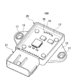
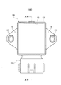
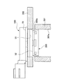
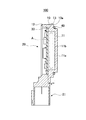
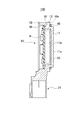
図1に、第1実施形態の、ステータモジュールの斜視図を示す。図2に、ステータモジュールの上面視図を示す。図3に、ステータモジュールの側面図を示す。図4に、ステータモジュールの下面視図を示す。図5に、ステータモジュールの断面図を示す。位置センサ150を構成するステータモジュール100は、ステータ筐体10と、回路基板30と、を備えている。ステータ筐体10は、プラスチック製であり射出成形されて形成されている。そして、図5に示される様に凹部20を備えており、凹部20は底部11と壁部12よりなる。壁部12には段差部13が凹部20の内側に向けて形成されている。
FIG. 1 is a perspective view of a stator module according to the first embodiment. FIG. 2 shows a top view of the stator module. FIG. 3 shows a side view of the stator module. FIG. 4 shows a bottom view of the stator module. FIG. 5 shows a cross-sectional view of the stator module. The
底部11は、図3に示される様にロータ200に面するロータ対向面11aと、内底面11bとを有する。段差部13の高さは内底面11bから距離xの位置に形成されており、段差部13に回路基板30が配置された段階で、内底面11bと回路基板30の下面とは距離xだけ離れた状態となる。一方のロータ対向面11aには励磁コイル51が形成されている。なお、励磁コイル51は内底面11bに形成されていても良い。励磁コイル51と回路基板30とは、図4に示される様なターミナル35によって接続されている。ターミナル35は、ステータ筐体10が射出成形される際に埋め込まれている。
The
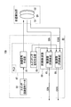
図6に、位置センサ150の構成を示す。回路基板30には、スイッチ82とPLD回路87と同期検波部88が設けられている。PLD回路87として励磁信号生成部81、スイッチング信号生成部83が設けられている。励磁信号生成部81にはスイッチ82が接続され、励磁信号データが付与されている。励磁信号生成部81は位置検出部50の励磁コイル51に接続されている。
FIG. 6 shows the configuration of the position sensor 150. The
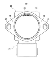
同期検波部88には、正弦波復調部85と余弦波復調部86が設けられている。正弦波復調部85と余弦波復調部86は励磁コイル51に接続されている。又、ステータ筐体10には、図1に示すようにフランジ部15とコネクタ部21が設けられている。フランジ部15にはボルト孔17が設けられ、図3に示すようにケース302に図示しないボルトで取り付けられる。
The
コネクタ部21は、外部電源や信号のやり取りをする図示しない端子を備えており、回路基板30に実装される素子からの電気信号などを外部とやり取りし、回路基板30や励磁コイル51に対して電力を供給するように、図示しないバスバが接続されている。ステータ筐体10の下面には図3に示される様にケース302に当接する当接面10aが形成され、当接面10aにはシール部材40が設けられる。シール部材40はOリングに用いられる様なゴム製部材が採用されている。
The
励磁コイル51に対向して配置される検出コイル52は、図示しないモータに備えられるモータシャフト301の先端に保持される。モータシャフト301の先端には、所定の深さに形成された保持溝301aが設けられている。この保持溝301aに検出コイル52が形成されたロータ200が保持されることで、ロータ200はモータシャフト301の回転に伴って回転する。そして、励磁コイル51と検出コイル52より位置検出部50が構成され、図6に示したような位置センサ150の回路構成によって、検出コイル52の回転に伴う位置検出や角度検出を実現する。
A
第1実施形態のモータに備えられた位置センサ150は上記構成であるので、以下に説明するような作用を奏する。 Since the position sensor 150 provided in the motor according to the first embodiment has the above-described configuration, the following effects are exhibited.
まず、ステータモジュール100の小型化が可能である点が効果として挙げられる。第1実施形態の位置センサ150は、回転軸に相当するモータシャフト301に取り付けられたロータ200と、ロータ200と対向する位置に配置されるステータモジュール100と、を有する位置センサ150において、ステータモジュール100は、樹脂製のステータ筐体10と、ロータ200と対向する位置に配置される励磁コイル51と、励磁コイル51から出力信号を処理する回路部が実装された回路基板30と、を備えている。
First, the effect is that the
また、ステータ筐体10は凹部20が形成され、凹部20は、ロータ200と対向する側に保持される底部11と、底部11より立設される壁部12と、壁部12の内側に形成される段差部13を有し、励磁コイル51は、底部11のロータと対向する側のロータ対向面11a(又は内底面11b)に配置され、段差部13に回路基板30が備えられ、段差部13が底部11から所定の距離に形成されることで、励磁コイル51と回路基板30とが離間し、重ねられるものである。
Further, the
位置センサ150はこの様な構成である為、回路基板30が励磁コイル51と重ねられるように配置される結果となる。したがって、回路基板30をステータモジュール100とは別の場所に配置するケースと比べ、省スペース化を図ることが可能となる。車載される位置センサ150は、小型化が望まれており、回路基板30を別の場所に配置することは極力避けたい。このため、第1実施形態に示すような省スペース化による恩恵は、単に回路基板30を別途配置するスペースを省略できるだけではなく、配線の省略や放熱対策にもなり得る。この結果、車両のコストダウン等に貢献することも可能である。
Since the position sensor 150 has such a configuration, the
また、第1実施形態のステータモジュール100を位置センサ150に用いることで、位置センサ150の検出精度の向上寄与できる点が挙げられる。ステータ筐体10は、壁部12の外周面から外側に延設されるフランジ部15を備え、フランジ部15は、底部11のロータ対向面11aよりロータ200と対向する側とは反対側に離間した位置に設けられており、段差部13はフランジ部15の取り付け面より更に離間した位置に形成されているものである。
In addition, by using the
つまりステータ筐体10に段差部13を設け、段差部13に回路基板30を配置することで、底部11に設けられる励磁コイル51と回路基板30との間を空けることができる。図5に示す空間Aが設けられる結果、励磁コイル51から回路基板30への回り込みを防ぐことができる。距離xが離れるほどノイズの影響を排除することができるため、ステータモジュール100のような構成は効果的であり、位置センサ150の精度向上にも貢献することができる。
That is, by providing the
また、励磁コイル51と回路基板30とは接続線部に相当するターミナル35で電気的に結ばれている。従来、回路基板30が位置センサ150の外部に設けられるケースでは、接続線を取り回す必要があった。この点、ターミナル35は底部11より回路基板30までの距離程度に抑えることができるため、接続線部から位置検出部50または回路基板30へノイズが回り込むリスクを低減させることができる。また、回路基板30及び励磁コイル51に対して垂直にターミナル35が設けられることで、形成される磁束の向きが、位置検出部50及び回路基板30に影響する可能性を低減することができる。結果、位置センサ150の検出精度の向上に寄与する。
Further, the
次に、本発明の第2の実施形態について説明する。第2実施形態は第1実施形態の位置センサ150の構成とほぼ同じであるが、ステータ筐体10の構成が若干異なる。
Next, a second embodiment of the present invention will be described. The second embodiment is substantially the same as the configuration of the position sensor 150 of the first embodiment, but the configuration of the
図7に、第2実施形態の、ステータモジュールの断面図を示す。図8に、ステータモジュールの下面視図を示す。図9に、ターミナル回りの拡大図を示す。ステータモジュール100の底部11には、内底面11bに接するように磁気シールド部材25が配置される。磁気シールド部材25は、金属板もしくは磁性シートを用いる。この結果、磁気シールド部材25の上に空間Aが形成されることになる。そして、図8及び図9に示される様に、ターミナル35の周囲にはターミナル防護用金属36が配置される。ターミナル防護
用金属36は筒状の金属体が用いられている。
FIG. 7 is a cross-sectional view of the stator module according to the second embodiment. FIG. 8 is a bottom view of the stator module. FIG. 9 shows an enlarged view around the terminal. A
第2実施形態の位置センサ150は、上記構成であるので、第1実施形態の位置センサ150と同等の作用及び効果を奏するが、更に以下に説明するような作用及び効果を得られる。 Since the position sensor 150 according to the second embodiment has the above-described configuration, the same effects and advantages as the position sensor 150 according to the first embodiment can be obtained. However, the actions and effects described below can be further obtained.
第2実施形態の位置センサ150には、磁気シールド部材25が設けられることで、回路基板30から励磁コイル51へのノイズの回り込みを防止することができる。ターミナル35から発生する磁束は、励磁コイル51または回路基板30へは磁束の向きが異なる為、影響を与え難い。しかしながら、ターミナル35の周囲にターミナル防護用金属36が設けられることで、更なる影響低減が可能となる。この結果、位置センサ150の検出精度の向上を図ることが可能となる。
The position sensor 150 of the second embodiment is provided with the
以上において、実施形態に即して説明したが、本発明は上記実施形態に限定されるものではなく、その要旨を逸脱しない範囲で、適宜変更して適用できることは言うまでもない。例えば、第1実施形態及び第2実施形態のステータモジュール100には、底部11のロータ対向面11a側に励磁コイル51を形成したが、内底面11b側に励磁コイル51を形成することを妨げない。また、位置センサ150に用いる材質を例示しているが、同じ効果を奏する異なる材質に変更することを妨げない。また、ステータモジュール100に用いるステータ筐体10の形状に関しても、発明の範囲内において設計変更することを妨げない。
While the present invention has been described with reference to the embodiments, it is needless to say that the present invention is not limited to the above-described embodiments, and can be appropriately modified and applied without departing from the scope of the invention. For example, in the
10 ステータ筐体
11 底部
11a ロータ対向面
11b 内底面
12 壁部
13 段差部
15 フランジ部
20 凹部
21 コネクタ部
25 磁気シールド部材
30 回路基板
35 ターミナル
50 位置検出部
100 ステータモジュール
150 位置センサ
200 ロータ
DESCRIPTION OF
Claims (3)
前記ステータは、
樹脂製のステータ筐体と、前記ロータと対向する位置に配置されるコイルと、該コイルから出力信号を処理する回路部が実装された回路基板と、を備え、
前記ステータ筐体は凹部が形成され、
前記凹部は、ロータと対向する側に保持される底部と、前記底部より立設される壁部と、前記壁部の内側に形成される段差部を有し、
前記コイルは、前記底部の前記ロータと対向する側のロータ対向面、又はその裏面である内底面の少なくともいずれか1面に配置され、前記段差部に前記回路基板が備えられ、
前記段差部が前記底部から所定の距離に形成されることで、前記コイルと前記回路基板とが離間し、重ねられること、
を特徴とする位置センサ。 In a position sensor having a rotor attached to a rotating shaft, and a stator disposed at a position facing the rotor,
The stator is
A resin stator housing, a coil disposed at a position facing the rotor, and a circuit board on which a circuit unit for processing an output signal from the coil is mounted;
The stator housing is formed with a recess,
The concave portion has a bottom portion held on the side facing the rotor, a wall portion standing from the bottom portion, and a step portion formed inside the wall portion,
The coil is disposed on at least one of a rotor facing surface on the side facing the rotor of the bottom portion or an inner bottom surface that is the back surface thereof, and the circuit board is provided in the stepped portion,
The stepped portion is formed at a predetermined distance from the bottom, so that the coil and the circuit board are separated from each other and overlapped.
A position sensor characterized by.
前記ステータ筐体は、前記壁部の外周面から外側に延設されるフランジ部を備え、
前記フランジ部は、前記底部の前記ロータ対向面より前記ロータと対向する側とは反対側に離間した位置に設けられており、
前記段差部は前記フランジ部の取り付け面より更に離間した位置に形成されていること、
を特徴とする位置センサ。 The position sensor according to claim 1,
The stator housing includes a flange portion extending outward from the outer peripheral surface of the wall portion,
The flange portion is provided at a position separated from the rotor facing surface of the bottom portion on the side opposite to the side facing the rotor,
The step portion is formed at a position further away from the mounting surface of the flange portion;
A position sensor characterized by.
前記回路基板と前記底部との間に磁気シールド部材が配置されていること、
を特徴とする位置センサ。 The position sensor according to claim 1 or 2,
A magnetic shield member is disposed between the circuit board and the bottom,
A position sensor characterized by.
Priority Applications (1)
| Application Number | Priority Date | Filing Date | Title |
|---|---|---|---|
| JP2013254180A JP2015114123A (en) | 2013-12-09 | 2013-12-09 | Position sensor |
Applications Claiming Priority (1)
| Application Number | Priority Date | Filing Date | Title |
|---|---|---|---|
| JP2013254180A JP2015114123A (en) | 2013-12-09 | 2013-12-09 | Position sensor |
Publications (1)
| Publication Number | Publication Date |
|---|---|
| JP2015114123A true JP2015114123A (en) | 2015-06-22 |
Family
ID=53528066
Family Applications (1)
| Application Number | Title | Priority Date | Filing Date |
|---|---|---|---|
| JP2013254180A Pending JP2015114123A (en) | 2013-12-09 | 2013-12-09 | Position sensor |
Country Status (1)
| Country | Link |
|---|---|
| JP (1) | JP2015114123A (en) |
-
2013
- 2013-12-09 JP JP2013254180A patent/JP2015114123A/en active Pending
Similar Documents
| Publication | Publication Date | Title |
|---|---|---|
| CN107925315B (en) | Electric drive device and electric power steering device | |
| JP5850263B2 (en) | Drive device | |
| EP3512078B1 (en) | Motor control device and electric power steering control device | |
| JP5496357B2 (en) | Motor drive control device for electric power steering | |
| CN106208537B (en) | Rotation angle detection device | |
| US10263499B2 (en) | Motor | |
| KR102112938B1 (en) | Electric drive and electric power steering | |
| US20090267430A1 (en) | Electric power steering apparatus | |
| CN103459236B (en) | Drive Unit Integrated Rotating Motor | |
| US9622349B2 (en) | Control device, and motor unit including control device | |
| JP5523044B2 (en) | Drive control device and motor unit | |
| CN111033973B (en) | Electric drive device | |
| JP2016207963A (en) | Electronic control device and drive device | |
| CN111133572B (en) | Assemblies of parts and electronics | |
| JP2015114123A (en) | Position sensor | |
| CN103516120B (en) | Motor | |
| JP2011083062A (en) | Motor unit | |
| KR20180092423A (en) | Motor | |
| KR20210090002A (en) | Motor | |
| JP2020124036A (en) | motor | |
| JP7666177B2 (en) | Drive unit | |
| KR20190010995A (en) | Motor and appartus for steering | |
| KR102515373B1 (en) | Motor assembly | |
| JP6418864B2 (en) | Electronic control unit | |
| KR20180122176A (en) | Motor |