JP2015114113A - Torque sensor, and electric power steering device equipped with the same - Google Patents
Torque sensor, and electric power steering device equipped with the same Download PDFInfo
- Publication number
- JP2015114113A JP2015114113A JP2013254006A JP2013254006A JP2015114113A JP 2015114113 A JP2015114113 A JP 2015114113A JP 2013254006 A JP2013254006 A JP 2013254006A JP 2013254006 A JP2013254006 A JP 2013254006A JP 2015114113 A JP2015114113 A JP 2015114113A
- Authority
- JP
- Japan
- Prior art keywords
- circuit
- torque sensor
- pair
- voltage
- torque
- Prior art date
- Legal status (The legal status is an assumption and is not a legal conclusion. Google has not performed a legal analysis and makes no representation as to the accuracy of the status listed.)
- Granted
Links
Images
Landscapes
- Steering Control In Accordance With Driving Conditions (AREA)
- Power Steering Mechanism (AREA)
Abstract
【課題】初期始動時に異常を判別することができるトルクセンサ及びそれを搭載した安全性の高い電動パワーステアリング装置を提供する。【解決手段】トルクに応じて互いに逆方向にインピーダンスが変化する1対の検出コイルL1、L2と、1対の検出コイルに直列接続されてブリッジ回路を形成する1対の抵抗を具備し、ブリッジ回路の電圧に基づいてトルクを検出するトルクセンサ回路150とで構成され、トルクセンサ回路に回路用電源電圧及び定電圧用基準電圧が供給され、トルクセンサ回路が、1対の検出コイルを励磁する励磁部と、励磁の電圧波形及びブリッジ回路の電圧波形を比較し、1対の検出コイルの異常を検出する監視部160とを具備しているトルクセンサにおいて、トルクセンサ回路に回路用電源電圧及び定電圧用基準電圧が入力されるタイミングで処理を行う付加回路部と、初期診断時に1対の検出コイルの間の短絡を検出する監視回路部とを備える。【選択図】図8A torque sensor capable of discriminating an abnormality at the time of initial start and a highly safe electric power steering apparatus equipped with the torque sensor are provided. A bridge includes a pair of detection coils L1 and L2 whose impedances change in opposite directions according to torque, and a pair of resistors connected in series to the pair of detection coils to form a bridge circuit. And a torque sensor circuit 150 for detecting torque based on the voltage of the circuit. A circuit power supply voltage and a constant voltage reference voltage are supplied to the torque sensor circuit, and the torque sensor circuit excites a pair of detection coils. In the torque sensor comprising the excitation unit, and a monitoring unit 160 that compares the excitation voltage waveform and the voltage waveform of the bridge circuit and detects an abnormality of the pair of detection coils, a circuit power supply voltage and It has an additional circuit section that performs processing at the timing when the reference voltage for constant voltage is input, and a monitoring circuit section that detects a short circuit between the pair of detection coils at the time of initial diagnosis. . [Selection] Figure 8
Description
本発明は、トルクセンサ及びそれを搭載し、車両の操舵系にモータによるアシスト力を付与するようにした電動パワーステアリング装置に関する。特に、発生するトルクに応じて互いに逆方向にインピーダンスが変化する1対の検出コイルと、1対の検出コイルに直列接続されてブリッジ回路を形成する1対の抵抗を具備し、ブリッジ回路の電圧差に基づいて操舵トルクを検出すると共に、検出コイルの異常(故障)を検出するトルクセンサ回路とで構成されたトルクセンサにおいて、初期診断で、1対の検出コイル同士が短絡した異常をも検出できるようにしたトルクセンサ及びそれを搭載した安全性の高い電動パワーステアリング装置に関する。 The present invention relates to a torque sensor and an electric power steering apparatus that is equipped with the torque sensor and applies an assist force by a motor to a steering system of a vehicle. In particular, it comprises a pair of detection coils whose impedances change in opposite directions according to the generated torque, and a pair of resistors connected in series to the pair of detection coils to form a bridge circuit. In the torque sensor composed of the torque sensor circuit that detects the steering torque based on the difference and detects the abnormality (failure) of the detection coil, it also detects an abnormality in which the pair of detection coils are short-circuited in the initial diagnosis. The present invention relates to a torque sensor that can be used and a highly safe electric power steering apparatus equipped with the torque sensor.
車両のステアリング機構にモータの回転力で操舵補助力(アシスト力)を付与する電動パワーステアリング装置は、モータの駆動力を減速機を介してギア又はベルト等の伝達機構により、ステアリングシャフト或いはラック軸に操舵補助力を付与するようになっている。かかる従来の電動パワーステアリング装置(EPS)は、操舵補助力のトルクを正確に発生させるため、モータ電流のフィードバック制御を行っている。フィードバック制御は、操舵補助指令値(電流指令値)とモータ電流検出値との差が小さくなるようにモータ印加電圧を調整するものであり、モータ印加電圧の調整は、一般的にPWM(パルス幅変調)制御のデューティの調整で行っている。 An electric power steering device that applies a steering assist force (assist force) to a steering mechanism of a vehicle by a rotational force of a motor, a steering shaft or a rack shaft by a transmission mechanism such as a gear or a belt via a speed reducer. A steering assist force is applied to the vehicle. Such a conventional electric power steering device (EPS) performs feedback control of the motor current in order to accurately generate the torque of the steering assist force. In feedback control, the motor applied voltage is adjusted so that the difference between the steering assist command value (current command value) and the motor current detection value is small. The adjustment of the motor applied voltage is generally performed by PWM (pulse width). This is done by adjusting the duty of modulation) control.
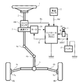
電動パワーステアリング装置の一般的な構成を図1に示して説明すると、ハンドル(ステアリングホイール)1のコラム軸(ステアリングシャフト、ハンドル軸)2は減速ギア3、ユニバーサルジョイント4a及び4b、ピニオンラック機構5、タイロッド6a,6bを経て、更にハブユニット7a,7bを介して操向車輪8L,8Rに連結されている。また、コラム軸2には、ハンドル1の操舵トルクを検出するトルクセンサ100が設けられており、ハンドル1の操舵力を補助するモータ20が減速ギア3を介してコラム軸2に連結されている。電動パワーステアリング装置を制御するコントロールユニット(ECU)30には、バッテリ13から電力(電圧VBAT)が供給されると共に、イグニションキー11を経てイグニションキー信号IGが入力される。コントロールユニット30は、トルクセンサ100で検出された操舵トルクThと車速センサ12で検出された車速Velとに基づいてアシスト(操舵補助)指令の電流指令値の演算を行い、電流指令値に補償等を施した電流制御値Eによってモータ20に供給する電流を制御する。
The general configuration of the electric power steering apparatus will be described with reference to FIG. The
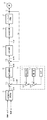
コントロールユニット30は主としてCPU(MPUやMCUも含む)で構成されるが、そのCPU内部においてプログラムで実行される一般的な機能を示すと図2のようになる。
The
図2を参照してコントロールユニット30の機能及び動作を説明すると、トルクセンサ100で検出された操舵トルクTh及び車速センサ12で検出された(若しくはCANからの)車速Velは、電流指令値Iref1を演算する電流指令値演算部31に入力される。電流指令値演算部31は、入力された操舵トルクTh及び車速Velに基づいてアシストマップ等を用いて、モータ20に供給する電流の制御目標値である電流指令値Iref1を演算する。電流指令値Iref1は加算部32Aを経て電流制限部33に入力され、過熱保護条件で最大電流を制限された電流指令値Iref3が減算部32Bに入力され、フィードバックされているモータ電流値Imとの偏差Iref4(=Iref3−Im)が演算され、その偏差Iref4が操舵動作の特性改善のためのPI制御部35に入力される。PI制御部35で特性改善された電圧制御指令値VrefがPWM制御部36に入力され、更に駆動部としてのインバータ回路37を介してモータ20がPWM駆動される。モータ20の電流値Imはモータ電流検出器38で検出され、減算部32Bにフィードバックされる。
The function and operation of the
また、加算部32Aには補償部34からの補償信号CMが加算されており、補償信号CMの加算によってシステム系の補償を行い、収れん性や慣性特性等を改善するようようになっている。補償部34は、セルフアライニングトルク(SAT)343と慣性342を加算部344で加算し、その加算結果に更に収れん性341を加算部345で加算し、加算部345の加算結果を補償信号CMとしている。
Further, the compensation signal CM from the
このように電動パワーステアリング装置では、操舵トルクThを検出するためのトルクセンサ100を搭載しており、トルクセンサ(例えば特開2001−159570号公報(特許文献1)、特許第3649057号公報(特許文献2))の概略の構造及び動作を以下に説明する。
As described above, the electric power steering apparatus is equipped with the
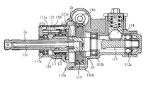
図3はトルクセンサ100を含む電動パワーステアリング装置の主要部を示す断面図であり、図4はトルクセンサ100の一部断面斜視図である。図3及び図4において、110a及び110bはハウジングであり、入力軸側110a及び出力軸側110bの2分割構造となっている。ハウジング110a及び110bの内部には、コラム軸2の入力軸2a、その内部に配置されたトーションバー111、トーションバー111を介して入力軸2aに連結された出力軸2bが、軸受112a、112b及び112cによって回転自在に支持されている。入力軸2a、トーションバー111及び出力軸2bは同軸に配置されており、入力軸2aとトーションバー111とはスプライン結合し、また、トーシヨンバー111と出力軸2bもスプライン結合している。また、出力軸2bにはピニオン軸113が一体的に形成されており、ピニオン軸113はラック114と噛合してラックアンドピニオン式ステアリング機構を構成している。
FIG. 3 is a cross-sectional view showing the main part of the electric power steering apparatus including the
なお、コラム式電動パワーステアリング装置においても、ピニオン軸113がコラム軸を呈しており、ほぼ同様な構造である。
In the column type electric power steering apparatus, the
出力軸2bには、これと同軸で且つ一体に回転するウォームホイール115が固着されており、モータ20で駆動されるウォーム116と噛合している。モータ20の回転力は、ウォーム116及びウォームホイール115を介して出力軸2bに伝達され、モータ20の回転方向を適宜切り換えることにより、出力軸2bに任意の方向の操舵補助トルクが付与される。
A
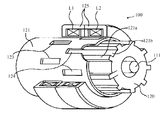
次に、トルクセンサ100のトルク検出部の構成を説明する。トルク検出部は入力軸2aのセンサシャフト部120と、ハウジング110aの内側に配置された1対の検出コイルL1,L2と、両者の間に配置された円筒部材121とから構成される。センサシャフト部120の表面には、軸方向に延びた複数の凸条121aが円周方向に沿って等間隔に形成されており、凸条121aの間にはその幅よりも幅広の溝部121bが形成されている。また、センサシャフト部120の外側には、導電性で且つ非磁性の材料で構成された円筒部材121が同軸に配置されており、円筒部材121の延長部121eは出力軸2bの端部2eの外側に固定されている。円筒部材121には、凸条121aに対向する位置に、円周方向に等間隔に配置された複数個の長方形の窓123から成る第1の窓列と、第1の窓列から軸方向にずれた位置に、円周方向の位相が異なる複数個の長方形の窓124から成る第2の窓列とが設けられている。
Next, the configuration of the torque detector of the
円筒部材121の外周は、検出コイルL1及びL2が捲回されたヨーク125で包囲されている。即ち、検出コイルL1及びL2は円筒部材121と同軸に配置され、検出コイルL1は第1の窓列部分を包囲し、検出コイルL2は第2の窓列部分を包囲する。ヨーク125はハウジング110aの内部に固定され、検出コイルL1及びL2のリード線は、ハウジング110aの内部に配置されたトルクセンサ回路(回路基板)150に接続される。
The outer periphery of the
操舵系が直進状態にあって操舵トルクThが零である場合はトーションバー111には捩れが発生せず、入力軸2aと出力軸2bとは相対回転しない。従って、入力軸2aの側にあるセンサシャフト部120の表面の凸条121aと、出力軸2bの側にある円筒部材121との間にも相対回転が生じない。一方、ハンドル1を操舵して入力軸2aに回転力が加わると、その回転力はトーションバー111を経て出力軸2bに伝達される。このとき、出力軸2bには舵輪と路面との間の摩擦力や出力軸2bに結合されているギアの噛み合い等の摩擦力が作用するから、入力軸2aと出力軸2bとの間を結合するトーションバー111に捩れが発生し、凸条121aと円筒部材121との間に相対回転が生ずる。
When the steering system is in the straight traveling state and the steering torque Th is zero, the torsion bar 111 is not twisted, and the
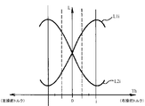
図5は、操舵トルクThの大きさと検出コイルL1のインダクタンスL1i及び検出コイルL2のインダクタンスL2iの変化例を示す特性図であり、互いに逆方向にインピーダンスが変化する。つまり、右操舵トルク発生時は、円筒部材121が時計方向に回転するから、操舵トルクThが増大するに従って検出コイルL1のインダクタンスL1iは増加し、検出コイルL2のインダクタンスL2iは減少する。また、左操舵トルク発生時は、円筒部材121が反時計方向に回転するから、操舵トルクThが増大するに従って検出コイルL1のインダクタンスL1iは減少し、検出コイルL2のインダクタンスL2iは増加する。
FIG. 5 is a characteristic diagram showing a change example of the magnitude of the steering torque Th, the inductance L1i of the detection coil L1, and the inductance L2i of the detection coil L2, and the impedances change in opposite directions. That is, when the right steering torque is generated, the
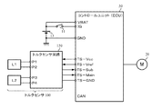
図6は、トルクセンサ100とコントロールユニット(ECU)30の電気的な接続関係を示しており、トルクセンサ100は1対の検出コイルL1,L2とトルクセンサ回路150とで構成され、検出コイルL1,L2とトルクセンサ回路150とはピンP1〜P4を介して接続されている。トルクセンサ回路150とコントロールユニット30とは接地部TS−GND(グランド)で共通接続されると共に、コントロールユニット30からトルクセンサ回路150へ回路用の電源電圧TS−Vcc、定電圧用の基準電圧TS−Vrefが供給され、トルクセンサ回路150からコントロールユニット30へ操舵トルクThを示すメイントルク信号TS−Mmain及びサブトルク信号TS−Subが入力される。
FIG. 6 shows an electrical connection relationship between the
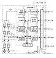
図7はトルクセンサ回路150の構成例を示しており、操舵トルクThを検出するブリッジ回路は、検出コイルL1及び抵抗Z1,Z2が直列に接続された第1アームと、検出コイルL2及び抵抗Z3,Z4が直列に接続された第2アームとから構成されている。発振部152は所定周波数の交流電圧を発振出力し、交流電圧は電流増幅部151で増幅され、増幅された交流電圧Voscが第1のアーム及び第2のアームに供給される。なお、トルクが作用していない状態で、ブリッジ回路の第1アーム及び第2アームに等しい電流が流れて検出コイルL1の端部(ピン)P1の電圧V3と、検出コイルL2の端部(ピン)P3の電圧V4とが等しくなるように、予め検出コイルL1及びL2の特性を揃え、また、抵抗Z1と抵抗Z2の接合点の電圧V3と抵抗Z3と抵抗Z4の接合点の電圧V4とが等しくなるように、抵抗Z1〜Z4を揃えておく。
FIG. 7 shows a configuration example of the
検出コイルL1の接合点P1の電圧V3と、検出コイルL2の接合点P3の電圧V4は、メイン増幅全波整流部153に入力され、その差分の電圧信号に変換されて増幅されると共に整流され、更にメイン平滑中立調整部155で出力波形が調整された後、ノイズフイルタ163を経てメイントルク信号TS−Mainとして出力される。また、抵抗Z1と抵抗Z2の接合点の電圧V1と、抵抗Z3と抵抗Z4の接合点の電圧V2は、サブ増幅全波整流部154に入力され、その差分の電圧信号に変換されて増幅されると共に整流され、更にサブ平滑中立調整部156で出力波形が調整された後、ノイズフイルタ163を経てサブトルク信号TS−Subとして出力される。
The voltage V3 at the junction point P1 of the detection coil L1 and the voltage V4 at the junction point P3 of the detection coil L2 are input to the main amplification full-
メイントルク信号TS−Main及びサブトルク信号TS−Subはコントロールユニット30に入力され、その差が零であるか零以外であるかを診断する。そして、零の場合はブリッジ回路を構成する回路要素は正常であると診断し、差が零以外の信号の場合は、ブリッジ回路を構成する回路要素が故障していると診断して、必要な処置、例えば警告表示をするほか、操舵トルクThを無効にするなどの処理をする。
The main torque signal TS-Main and the sub torque signal TS-Sub are input to the
上述した従来のトルクセンサ(特許文献1及び2)ではブリッジ回路を構成しているので、ピンP1とピンP3が短絡した場合には電圧V3及びV4が同一になってしまい、全体のインピーダンス変化が発生しても一定値となってしまう。このようなピン間が短絡したようなトルクセンサを搭載した電動パワーステアリング装置では、トルク入力が一定のアシスト制御になってしまい、運転者がハンドルを操舵してもアシストされず、マニュアルステアリングとなってしまい、運転者に不快感を与えてしまう。
Since the conventional torque sensor (
また、ピン間の短絡を検出するトクセンサとして、特開2000−111428号公報(特許文献3)に開示されたものがある。特許文献3のトルクセンサでは、コイル同士が短絡した異常(故障)を検出する手法を示しているが、コントロールユニット(ECU)の構成を大幅に変更しなくてはならない問題がある。つまり、特許文献3のトルクセンサでは、従来のコントロールユニット(ECU)をそのまま使用することができないので、コストアップにもなる。
Moreover, there exists a thing disclosed by Unexamined-Japanese-Patent No. 2000-111428 (patent document 3) as a value sensor which detects the short circuit between pins. The torque sensor disclosed in
本発明は上述のような事情よりなされたものであり、本発明の目的は、従来のトルクセンサ回路のASIC(Application Specific Integrated Circuit、カスタムIC)で構成された部分には一切手を加えず、コントロールユニット(ECU)のハードウェア構成、フェールセーフ構成を変えず、極めて簡易な構成(付加回路部)の付加により検出コイル同士の短絡を検出することができ、初期始動時に異常(故障)を判別することができるトルクセンサ及びそれを搭載した安全性の高い電動パワーステアリング装置を提供することにある。 The present invention has been made in the circumstances as described above, and the object of the present invention is to make no changes to the portion of the conventional torque sensor circuit configured by ASIC (Application Specific Integrated Circuit, custom IC), Without changing the hardware configuration and fail-safe configuration of the control unit (ECU), it is possible to detect a short circuit between detection coils by adding an extremely simple configuration (additional circuit section), and to detect abnormalities (failures) at the initial start It is an object of the present invention to provide a torque sensor that can be used and a highly safe electric power steering apparatus equipped with the torque sensor.
本発明は、回転軸に生じるトルクに応じて互いに逆方向にインピーダンスが変化する1対の検出コイルと、前記1対の検出コイルに直列接続されてブリッジ回路を形成する1対の抵抗を具備し、前記ブリッジ回路の電圧に基づいて前記トルクを検出するトルクセンサ回路とで構成され、前記トルクセンサ回路に回路用電源電圧及び定電圧用基準電圧が供給され、前記トルクセンサ回路が、前記1対の検出コイルを励磁する励磁部と、前記励磁の電圧波形及び前記ブリッジ回路の電圧波形を比較し、前記1対の検出コイルの異常を検出する監視部とを具備しているトルクセンサに関し、本発明の上記目的は、前記トルクセンサ回路に前記回路用電源電圧及び定電圧用基準電圧が入力されるタイミングで処理を行う付加回路部と、初期診断時に前記1対の検出コイルの間の短絡を検出する監視回路部とを備えることにより達成される。 The present invention includes a pair of detection coils whose impedances change in opposite directions according to the torque generated on the rotating shaft, and a pair of resistors connected in series to the pair of detection coils to form a bridge circuit. And a torque sensor circuit for detecting the torque based on the voltage of the bridge circuit, a circuit power supply voltage and a constant voltage reference voltage are supplied to the torque sensor circuit, and the torque sensor circuit is connected to the pair of torque sensors. The present invention relates to a torque sensor comprising: an excitation unit that excites the detection coil; and a monitoring unit that compares the excitation voltage waveform and the voltage waveform of the bridge circuit and detects an abnormality of the pair of detection coils. The above object of the invention is to provide an additional circuit section that performs processing at a timing when the circuit power supply voltage and the constant voltage reference voltage are input to the torque sensor circuit, It is achieved by providing a monitoring circuit for detecting a short circuit between the pair of detection coils.
本発明の上記目的は、前記付加回路部が、ワンショットパルスを発生するワンショットパルス発生部と、前記ワンショットパルスに基づいてON/OFF動作を行い、前記監視回路部に診断信号を入力するスイッチング部とで構成されていることにより、或いは前記トルクセンサ回路がメイン回路部及びサブ回路部で構成されており、前記監視回路部で前記短絡が検出されたときに、前記サブ回路部から短絡検出信号を出力することにより、或いは前記スイッチング部が、前記1対の検出コイルの間に接続され、前記ワンショットパルスを入力する1対のスイッチング素子と、前記1対のスイッチング素子の一方に接続された出力用スイッチング素子とで構成され、前記出力用スイッチング素子から前記診断信号を出力し、前記サブ回路部を介して前記短絡検出信号を生成するようになっていることにより、或いは前記スイッチング部が、前記1対の検出コイルの間に接続され、前記ワンショットパルスを入力する1対のスイッチング素子と、前記1対のスイッチング素子の一方に接続された出力用スイッチング素子と、前記出力用スイッチング素子の出力信号及び基準電圧を比較して前記診断信号を生成するコンパレータとで構成され、前記コンパレータからの前記診断信号に基づき、前記サブ回路部を介して前記短絡検出信号を生成するようになっていることにより、或いは前記1対のスイッチング素子及び前記出力用スイッチング素子がトランジスタであることにより、より効果的に達成される。 The above-described object of the present invention is to provide the one-shot pulse generating unit that generates the one-shot pulse and the ON / OFF operation based on the one-shot pulse, and the diagnostic circuit is input to the monitoring circuit unit. A short circuit from the sub circuit unit when the short circuit is detected by the monitoring circuit unit. By outputting a detection signal or when the switching unit is connected between the pair of detection coils and connected to one of the pair of switching elements for inputting the one-shot pulse and one of the pair of switching elements The output switching element, outputting the diagnostic signal from the output switching element, The short-circuit detection signal is generated, or the switching unit is connected between the pair of detection coils, and the pair of switching elements for inputting the one-shot pulse; An output switching element connected to one of the pair of switching elements, and a comparator that compares the output signal of the output switching element and a reference voltage to generate the diagnostic signal, and the diagnosis from the comparator Based on the signal, the short circuit detection signal is generated via the sub-circuit unit, or the pair of switching elements and the output switching element are transistors, thereby more effectively. Achieved.
また、上記トルクセンサを搭載することにより、安全性の高い電動パワーステアリング装置を達成できる。 In addition, by mounting the torque sensor, a highly safe electric power steering apparatus can be achieved.
本発明のトルクセンサによれば、従来のトルクセンサ回路のASICで構成された部分には一切手を加えず、コントロールユニット(ECU)のハードウェア構成、フェールセーフ構成を変えず、極めて簡易な構成(付加回路部)の付加により検出コイル同士の短絡を検出することができるので、フェールに入らない固着モード(操舵トルク入力が一定)から逸脱できると共に、コストアップを最小限に抑えることができる。 According to the torque sensor of the present invention, no changes are made to the portion of the conventional torque sensor circuit configured by the ASIC, and the hardware configuration and fail-safe configuration of the control unit (ECU) are not changed. By adding the (additional circuit unit), it is possible to detect a short circuit between the detection coils, so that it is possible to deviate from the fixing mode (the steering torque input is constant) that does not enter the failure, and the cost increase can be minimized.
また、本発明のトルクセンサを搭載した電動パワーステアリング装置によれば、初期始動時に異常(故障)を判別することができ、エンジン始動時の初期診断で検出し、車両のインジケータ等に表示して運転者へ通知し、EPSに故障(異常)、アシスト制御がONしていないことを報知できる安全性の高い電動パワーステアリング装置を得ることができる。 Further, according to the electric power steering apparatus equipped with the torque sensor of the present invention, an abnormality (failure) can be determined at the initial start, detected by the initial diagnosis at the engine start, and displayed on the vehicle indicator or the like. It is possible to obtain a highly safe electric power steering apparatus capable of notifying the driver and notifying the EPS of the failure (abnormality) and the fact that the assist control is not ON.
本発明のトルクセンサによれば、従来のトルクセンサ回路のASICで構成された部分には一切手を加えず、しかもコントロールユニット(ECU)のハードウェア構成、フェールセーフ構成を変えず、ワンショットパルスを発生するワンショット発生部と、数個のスイッチング素子(例えばトランジスタ)等のスイッチング部とで成る極めて簡易な構成の付加回路部の付加により、初期診断時に検出コイル同士の短絡を、監視回路部を介して検出することができる。 According to the torque sensor of the present invention, the one-shot pulse is not changed without changing any part of the conventional ASIC of the torque sensor circuit, and without changing the hardware configuration and fail-safe configuration of the control unit (ECU). By adding an additional circuit unit with a very simple configuration consisting of a one-shot generating unit that generates a switching element and switching units such as several switching elements (for example, transistors), the monitoring circuit unit Can be detected.
また、本発明のトルクセンサを搭載した電動パワーステアリング装置によれば、初期始動時に検出コイル同士の短絡といった重大な異常(故障)を検知することができるので、エンジン始動時の初期診断時に検出コイルのコイル短絡を検出し、車両のインジケータ等に表示することにより運転者へ通知できる。これにより、EPSに故障(異常)があったり、アシスト制御がONしていないことを運転者に報知できる安全性の高い電動パワーステアリング装置を得ることができる。 In addition, according to the electric power steering apparatus equipped with the torque sensor of the present invention, since it is possible to detect a serious abnormality (failure) such as a short circuit between the detection coils at the initial start, the detection coil at the initial diagnosis at the engine start The driver can be notified by detecting the short circuit of the coil and displaying it on the indicator of the vehicle. As a result, it is possible to obtain a highly safe electric power steering apparatus capable of notifying the driver that there is a failure (abnormality) in the EPS or that the assist control is not ON.
以下に、本発明の実施の形態を、図面を参照して詳細に説明する。 Embodiments of the present invention will be described below in detail with reference to the drawings.
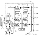
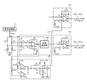
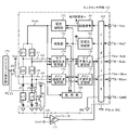
図8は本発明に係るトルクセンサの構成例を、従来の図7と対応させて示している。本発明では、ASICのトルクセンサ回路150に、回路用電源電圧(Vcc)及び定電圧用基準電圧(Vref)が入力されるタイミングで処理を行う付加回路部を付加している。付加回路部は、上記タイミングでワンショトパルスPLを発生するワンショット発生部(例えばモノマルチ)170と、ワンショットパルスPLに基づいてON/OFF動作を行い、診断信号V5を出力するスイッチング部とで構成されている。スイッチング部は、本実施形態では、スイッチング素子としての1対のトランジスタQ1及びQ2と、出力用スイッチング素子としての出力用トランジスタQ3とで構成されている。
FIG. 8 shows a configuration example of the torque sensor according to the present invention in correspondence with the conventional FIG. In the present invention, an additional circuit unit that performs processing at the timing when the circuit power supply voltage (Vcc) and the constant voltage reference voltage (Vref) are input is added to the
ワンショット発生部170からのワンショトパルスPLは、1対のトランジスタQ1及びQ2の各ベースに入力される。トランジスタQ1のコレクタは抵抗Z5を経て電源電圧Vccに接続され、エミッタはピンP1部分(検出コイルL1と抵抗Z2の接続点)に接続され、トランジスタQ2のコレクタはピンP2部分(検出コイルL2と抵抗Z4の接続点)に接続されている。また、トランジスタQ2のエミッタは出力用トランジスタQ3のベースに接続され、出力用トランジスタQ3のコレクタは抵抗Z6を経て電源電圧Vccに接続され、エミッタは接地されている。出力用トランジスタQ3のコレクタ出力V5が診断信号として監視部160に入力されている。
The one-shot pulse PL from the one-
また、本発明の監視部160はピンP1とピンP3との間の短絡が検出されたとき、短絡検出信号として、サブ平滑中立調整部156の出力であるサブ出力TSa−Subを論理「L」とするようになっている。なお、論理回路を逆とし、短絡が検出されたときに論理「H」とするように設計することも可能である。
Further, when a short circuit between the pin P1 and the pin P3 is detected, the
図9はトルクセンサ回路150の一部を詳細に示す回路図であり、監視部160内のCP1及びCP2は比較結果を論理「H」又は「L」で出力するコンパレータであり、メイン増幅全波整流部153内のOP1、メイン平滑中立調整部155内のOP2、サブ平滑中立調整部156内のOP3はいずれも演算増幅器であり、演算増幅器OP2からメイン出力TSa−Mainが出力され、演算増幅器OP3からサブ出力TSa−Subが出力される。
FIG. 9 is a circuit diagram showing a part of the
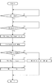
このような構成において、その動作例を図10のフローチャートに従って説明する。 In such a configuration, an example of the operation will be described with reference to the flowchart of FIG.
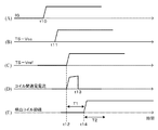
イグニションキー11がON(ステップS1)された初期状態(図11(A)の時点t10)においては、コントロールユニット30よりトルクセンサ回路150に回路用の電源電圧TS−Vcc、定電圧用の基準電圧TS−Vrefが入力されていないので、ワンショット発生部170からはワンショットパルスPLは発生されておらず、トランジスタQ1及びQ2はいずれもOFFとなっている。
In an initial state where the ignition key 11 is turned on (step S1) (time t10 in FIG. 11A), the
時点t10にイグニションキー11がONされ、初期診断が開始されると(ステップS2)、図11(B)に示す時点t11にコントロールユニット30より回路用の電源電圧TS−Vccが入力され、図11(C)に示す時点t11に定電圧用の基準電圧TS−Vrefが入力される(ステップS3)。基準電圧TS−Vrefが入力されると、図11(E)に示すように基準電圧TS−Vrefの入力時点t12から、検出コイルL1,L2の励磁開始時点t14までの間にワンショット発生部170よりワンショットパルスPLを発生し(ステップS4)、図11(D)に示すようにコイル間(ピンP1とピンP3の間)を通電電流させてコイル間短絡の有無をチェックする(ステップS5)。
When the ignition key 11 is turned on at time t10 and the initial diagnosis is started (step S2), the power supply voltage TS-Vcc for the circuit is input from the
コイル間の短絡チェックがOKであれば、図11(E)に示すように検出コイルL1、L2を時点t14以降励磁して診断を終了する(ステップS6)。つまり、時点t12から時点t14までの時間T1内にコイル間の短絡チェックを終了する。 If the short-circuit check between the coils is OK, as shown in FIG. 11E, the detection coils L1 and L2 are excited after time t14 and the diagnosis is terminated (step S6). That is, the short-circuit check between the coils is completed within a time T1 from time t12 to time t14.
上記ステップS5におけるコイル間の短絡チェックがOKでない場合、つまり検出コイル間(ピンP1とピンP3)の短絡がある場合には、出力用トランジスタQ3がONすることによってコレクタ出力V5が接地電位となり、監視部160を経てサブ信号TSa−Subが論理「L」となり(ステップS7)、コントロールユニット30側でこれを検知し、インジケータ等で表示する(ステップS8)。
If the short-circuit check between the coils in step S5 is not OK, that is, if there is a short-circuit between the detection coils (pins P1 and P3), the output transistor Q3 is turned ON, and the collector output V5 becomes the ground potential. The sub signal TSa-Sub becomes logic “L” through the monitoring unit 160 (step S7), and this is detected on the
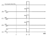
図12のタイミングチャートは、コイル間が短絡している場合のワンショットパルスPLと、トランジスタQ1〜Q3のON/OFFと、トランジスタQ3のコレクタ出力V5との関係を示している。 The timing chart of FIG. 12 shows the relationship among the one-shot pulse PL when the coils are short-circuited, ON / OFF of the transistors Q1 to Q3, and the collector output V5 of the transistor Q3.
ワンショットパルスPLが出力されていないとき、例えば時点t1においてはトランジスタQ1及びQ2はいずれもOFFとなっており、出力用トランジスタQ2のエミッタがトランジスタQ3のベースに接続されているので出力用トランジスタQ3はOFFであり、出力用トランジスタQ3のコレクタ出力は基準電圧Vccと同じ論理「H」となる。一方、時点t2にワンショットパルスPLが入力されるとトランジスタQ1及びQ2はいずれもONとなり、これにより出力用トランジスタQ3がONとなるので、トランジスタQ3のコレクタ出力V5が接地レベルの論理「L」となる。 When the one-shot pulse PL is not output, for example, at time t1, the transistors Q1 and Q2 are both OFF and the emitter of the output transistor Q2 is connected to the base of the transistor Q3, so that the output transistor Q3 Is OFF, and the collector output of the output transistor Q3 has the same logic “H” as the reference voltage Vcc. On the other hand, when the one-shot pulse PL is input at the time t2, both the transistors Q1 and Q2 are turned on, thereby turning on the output transistor Q3. Therefore, the collector output V5 of the transistor Q3 is at the logic level “L”. It becomes.
図13は本発明の他の実施形態を示しており、本実施形態では、付加回路部のスイッチング部が、1対のトランジスタQ1及びQ2と、出力用トランジスタQ3と、トランジスタQ3のコレクタに接続されたコンパレータ171とで構成されている。出力用トランジスタQ3のコレクタ出力V5をコンパレータ171の入力とし、コンパレータ171は基準電圧Vrefcと比較し、診断信号として論理「H」又は「L」のサブ信号TSa−Subを出力するようにしている。
FIG. 13 shows another embodiment of the present invention. In this embodiment, the switching section of the additional circuit section is connected to a pair of transistors Q1 and Q2, an output transistor Q3, and a collector of the transistor Q3. And a
本実施形態においては、短時間チェックを行う始動時はコントロールユニット(ECU)30側で、トルクメイン信号TS−Main及びサブトルク信号TS−Subを取り込んでいないため、ある程度の状態保持回路が必要である。そのため、出力用トランジスタQ3のベースと接地との間にキャパシタC1が接続され、ベース電位を保持するようになっている。また、本実施形態では検出コイルの励磁開始後に信号が出力されるタイミングでサブ信号TSa−Subを強制的に論理「L」としている。そのため、図11(E)に示す時間T2内に、つまり検出コイルの励磁後にコイル間短絡チェックを行う。 In the present embodiment, since the torque main signal TS-Main and the sub torque signal TS-Sub are not captured on the control unit (ECU) 30 side at the time of starting for a short time check, a certain state holding circuit is required. . Therefore, the capacitor C1 is connected between the base of the output transistor Q3 and the ground so as to hold the base potential. In this embodiment, the sub-signal TSa-Sub is forcibly set to logic “L” at the timing when a signal is output after the excitation of the detection coil is started. Therefore, a short circuit check between the coils is performed within a time T2 shown in FIG. 11E, that is, after excitation of the detection coil.
上述ではスイッチング素子としてトランジスタを用いているが、他の半導体素子を使用しても良い。また、上述の実施形態では半導体素子としてトランジスタをPNP型で説明しているが、NPN型で構成することも可能である。 In the above description, a transistor is used as a switching element, but other semiconductor elements may be used. In the above-described embodiment, the transistor is described as the PNP type as the semiconductor element, but may be configured as an NPN type.
1 ハンドル(ステアリングホイール)
2 コラム軸(ステアリングシャフト、ハンドル軸)
12 車速センサ
13 バッテリ
20 モータ
30 コントロールユニット(ECU)
31 電流指令値演算部
33 電流制限部
34 補償部
35 PI制御部
36 PWM制御部
37 インバータ回路
100 トルクセンサ
111 トーションバー
113 ピニオン軸
115 ウォームホイール
116 ウォーム
120 センサシャフト部
150 トルクセンサ回路(回路基板)
160 監視部
170 ワンショット発生部
171 コンパレータ
1 Handle (steering wheel)
2 Column shaft (steering shaft, handle shaft)
12
31 current command
Claims (7)
前記トルクセンサ回路に回路用電源電圧及び定電圧用基準電圧が供給され、前記トルクセンサ回路が、前記1対の検出コイルを励磁する励磁部と、前記励磁の電圧波形及び前記ブリッジ回路の電圧波形を比較し、前記1対の検出コイルの異常を検出する監視部とを具備しているトルクセンサにおいて、
前記トルクセンサ回路に前記回路用電源電圧及び定電圧用基準電圧が入力されるタイミングで処理を行う付加回路部と、初期診断時に前記1対の検出コイルの間の短絡を検出する監視回路部とを備えたことを特徴とするトルクセンサ。 A pair of detection coils whose impedances change in opposite directions according to torque generated on the rotation shaft, and a pair of resistors connected in series to the pair of detection coils to form a bridge circuit; And a torque sensor circuit that detects the torque based on the voltage of
A circuit power supply voltage and a constant voltage reference voltage are supplied to the torque sensor circuit, and the torque sensor circuit excites the pair of detection coils, a voltage waveform of the excitation, and a voltage waveform of the bridge circuit. And a torque sensor comprising a monitoring unit for detecting an abnormality of the pair of detection coils,
An additional circuit section that performs processing at the timing when the circuit power supply voltage and the constant voltage reference voltage are input to the torque sensor circuit; and a monitoring circuit section that detects a short circuit between the pair of detection coils during initial diagnosis. A torque sensor comprising:
Priority Applications (1)
| Application Number | Priority Date | Filing Date | Title |
|---|---|---|---|
| JP2013254006A JP6164073B2 (en) | 2013-12-09 | 2013-12-09 | Torque sensor and electric power steering apparatus equipped with the same |
Applications Claiming Priority (1)
| Application Number | Priority Date | Filing Date | Title |
|---|---|---|---|
| JP2013254006A JP6164073B2 (en) | 2013-12-09 | 2013-12-09 | Torque sensor and electric power steering apparatus equipped with the same |
Publications (2)
| Publication Number | Publication Date |
|---|---|
| JP2015114113A true JP2015114113A (en) | 2015-06-22 |
| JP6164073B2 JP6164073B2 (en) | 2017-07-19 |
Family
ID=53528059
Family Applications (1)
| Application Number | Title | Priority Date | Filing Date |
|---|---|---|---|
| JP2013254006A Expired - Fee Related JP6164073B2 (en) | 2013-12-09 | 2013-12-09 | Torque sensor and electric power steering apparatus equipped with the same |
Country Status (1)
| Country | Link |
|---|---|
| JP (1) | JP6164073B2 (en) |
Cited By (1)
| Publication number | Priority date | Publication date | Assignee | Title |
|---|---|---|---|---|
| JP2017103899A (en) * | 2015-12-01 | 2017-06-08 | 日本精工株式会社 | Motor control device and electric power steering device including the same |
Citations (3)
| Publication number | Priority date | Publication date | Assignee | Title |
|---|---|---|---|---|
| JP2000111428A (en) * | 1998-10-01 | 2000-04-21 | Nsk Ltd | Torque sensor |
| JP2010184669A (en) * | 2009-02-13 | 2010-08-26 | Nsk Ltd | Control device of electric power steering device |
| JP2012017026A (en) * | 2010-07-08 | 2012-01-26 | Nsk Ltd | Electric power steering device |
-
2013
- 2013-12-09 JP JP2013254006A patent/JP6164073B2/en not_active Expired - Fee Related
Patent Citations (4)
| Publication number | Priority date | Publication date | Assignee | Title |
|---|---|---|---|---|
| JP2000111428A (en) * | 1998-10-01 | 2000-04-21 | Nsk Ltd | Torque sensor |
| US6386052B1 (en) * | 1998-10-01 | 2002-05-14 | Nsk Ltd. | Torque sensor |
| JP2010184669A (en) * | 2009-02-13 | 2010-08-26 | Nsk Ltd | Control device of electric power steering device |
| JP2012017026A (en) * | 2010-07-08 | 2012-01-26 | Nsk Ltd | Electric power steering device |
Cited By (1)
| Publication number | Priority date | Publication date | Assignee | Title |
|---|---|---|---|---|
| JP2017103899A (en) * | 2015-12-01 | 2017-06-08 | 日本精工株式会社 | Motor control device and electric power steering device including the same |
Also Published As
| Publication number | Publication date |
|---|---|
| JP6164073B2 (en) | 2017-07-19 |
Similar Documents
| Publication | Publication Date | Title |
|---|---|---|
| US6386052B1 (en) | Torque sensor | |
| US11084523B2 (en) | Vehicle-mounted device actuator and power steering device | |
| JP6179646B2 (en) | Steering angle detection device for vehicle and electric power steering device equipped with the same | |
| CN103080715B (en) | Torque detection device | |
| US8204647B2 (en) | Electric power steering system | |
| JP6237565B2 (en) | Rotating electrical machine control device and electric power steering device using the same | |
| CN104136899A (en) | Relative angle detection device and electric power steering device | |
| US10530282B2 (en) | Current capability limiting of DC machines | |
| US9669812B2 (en) | Electric power steering system | |
| JP2009073446A (en) | Electric power steering device | |
| JP2010184669A (en) | Control device of electric power steering device | |
| JP6164073B2 (en) | Torque sensor and electric power steering apparatus equipped with the same | |
| JP2005147733A (en) | Abnormality detecting device, abnormality detection method and steering unit for vehicle | |
| JP2006267045A (en) | Torque sensor | |
| JP2012111335A (en) | Electric power steering system, failure detecting system and failure detecting method | |
| JP5455515B2 (en) | Electric power steering device, control method and program for electric power steering device | |
| JP5018577B2 (en) | Electric power steering device | |
| JP5265410B2 (en) | ELECTRIC POWER STEERING DEVICE, ITS CONTROL METHOD, AND PROGRAM | |
| JP5266913B2 (en) | Control device for electric power steering device | |
| JP2012112778A (en) | Failure detection device, failure detection method, and electric power steering device | |
| JP2857903B2 (en) | Electric power steering device | |
| JP2012017026A (en) | Electric power steering device | |
| JP6582935B2 (en) | Motor control device and electric power steering device provided with the same | |
| JP2012173009A (en) | Torque sensor and motor-driven power steering device with the same | |
| JP2014153097A (en) | Angle sensor, torque sensor, and power steering device |
Legal Events
| Date | Code | Title | Description |
|---|---|---|---|
| A621 | Written request for application examination |
Free format text: JAPANESE INTERMEDIATE CODE: A621 Effective date: 20160711 |
|
| A977 | Report on retrieval |
Free format text: JAPANESE INTERMEDIATE CODE: A971007 Effective date: 20170421 |
|
| A131 | Notification of reasons for refusal |
Free format text: JAPANESE INTERMEDIATE CODE: A131 Effective date: 20170509 |
|
| A521 | Request for written amendment filed |
Free format text: JAPANESE INTERMEDIATE CODE: A523 Effective date: 20170511 |
|
| TRDD | Decision of grant or rejection written | ||
| A01 | Written decision to grant a patent or to grant a registration (utility model) |
Free format text: JAPANESE INTERMEDIATE CODE: A01 Effective date: 20170523 |
|
| A61 | First payment of annual fees (during grant procedure) |
Free format text: JAPANESE INTERMEDIATE CODE: A61 Effective date: 20170605 |
|
| R150 | Certificate of patent or registration of utility model |
Ref document number: 6164073 Country of ref document: JP Free format text: JAPANESE INTERMEDIATE CODE: R150 |
|
| LAPS | Cancellation because of no payment of annual fees |