JP2015113100A - Information acquisition system and unmanned flight body controller - Google Patents
Information acquisition system and unmanned flight body controller Download PDFInfo
- Publication number
- JP2015113100A JP2015113100A JP2013259169A JP2013259169A JP2015113100A JP 2015113100 A JP2015113100 A JP 2015113100A JP 2013259169 A JP2013259169 A JP 2013259169A JP 2013259169 A JP2013259169 A JP 2013259169A JP 2015113100 A JP2015113100 A JP 2015113100A
- Authority
- JP
- Japan
- Prior art keywords
- flight
- air vehicle
- unmanned air
- information acquisition
- obstacle
- Prior art date
- Legal status (The legal status is an assumption and is not a legal conclusion. Google has not performed a legal analysis and makes no representation as to the accuracy of the status listed.)
- Granted
Links
- 238000004891 communication Methods 0.000 claims abstract description 34
- 238000003384 imaging method Methods 0.000 abstract description 112
- 238000005259 measurement Methods 0.000 abstract description 31
- 238000000034 method Methods 0.000 description 16
- 238000010586 diagram Methods 0.000 description 13
- 230000001133 acceleration Effects 0.000 description 5
- 238000012545 processing Methods 0.000 description 5
- 238000012937 correction Methods 0.000 description 3
- 238000001514 detection method Methods 0.000 description 2
- 235000015842 Hesperis Nutrition 0.000 description 1
- 235000012633 Iberis amara Nutrition 0.000 description 1
- 230000000694 effects Effects 0.000 description 1
- 230000001678 irradiating effect Effects 0.000 description 1
- 239000004973 liquid crystal related substance Substances 0.000 description 1
- 238000012986 modification Methods 0.000 description 1
- 230000004048 modification Effects 0.000 description 1
- 230000002093 peripheral effect Effects 0.000 description 1
Images


Abstract
Description
本発明は、無線通信によって無人飛行体を制御して飛行させ、無人飛行体によって目標物の情報を取得する技術に関する。 The present invention relates to a technique for controlling an unmanned air vehicle to fly by wireless communication and acquiring target information by the unmanned air vehicle.
特許文献1には、予め記憶させた飛行ルートに沿ってラジコンヘリコプタを飛行させる空中撮影システムが提案されている。
ところで、飛行する撮影現場の構造物の状況は、リアルタイムで変化する。
しかし、特許文献1のように、飛行する撮影現場のリアルタイムの状況とは関係なく予め記憶させた飛行ルートに沿ってラジコンヘリコプタを飛行させると、ラジコンヘリコプタが撮影現場の構造物に接触してしまう可能性がある。
By the way, the situation of the structure at the shooting site that flies changes in real time.
However, as in
本発明の目的は、ラジコンヘリコプタが飛行する現場のリアルタイムの状況に適合させてラジコンヘリコプタを飛行させることを可能にすることである。 An object of the present invention is to allow a radio controlled helicopter to fly in conformity with the real-time situation of the field where the radio controlled helicopter flies.
前記課題を解決するために、(1)本発明の一態様は、測量を行う測量装置と、情報を取得する対象となる情報取得目標物の情報を取得する無人飛行体と、前記無人飛行体との無線通信によって前記無人飛行体の飛行状態を制御して前記無人飛行体を前記情報取得目標物の情報を取得できる情報取得可能領域に飛行させる無人飛行体制御装置と、を有する情報取得システムであって、前記測量装置は、前記情報取得目標物の位置、前記無人飛行体の位置、及び前記情報取得可能領域に飛行する前記無人飛行体の飛行の障害になり得る飛行時障害物を測量し、前記無人飛行体制御装置は、前記測量装置の測量結果を基に、前記無人飛行体が前記飛行時障害物に接触することなく前記情報取得可能領域に飛行できる飛行経路を算出し、算出した飛行経路及び飛行中の前記無人飛行体の飛行状態を基に、前記無人飛行体との無線通信による前記無人飛行体の飛行状態の制御を行い前記無人飛行体を前記情報取得可能領域に飛行させることを特徴とする情報取得システムを提供する。 In order to solve the above-described problems, (1) one aspect of the present invention is a surveying device that performs surveying, an unmanned air vehicle that acquires information on an information acquisition target that is a target for acquiring information, and the unmanned air vehicle. An unmanned air vehicle control device that controls the flight state of the unmanned air vehicle by wireless communication with the unmanned air vehicle and causes the unmanned air vehicle to fly to an information obtainable area where the information of the information acquisition target can be obtained. The surveying device surveys a position of the information acquisition target, a position of the unmanned air vehicle, and an obstacle at the time of flight that may become an obstacle to the flight of the unmanned air vehicle flying in the information acquisition area. The unmanned aerial vehicle control device calculates a flight path on which the unmanned air vehicle can fly to the information acquirable area without contacting the obstacle during the flight, based on the survey result of the surveying device. Flying Based on the route and the flight state of the unmanned air vehicle in flight, the flight state of the unmanned air vehicle is controlled by wireless communication with the unmanned air vehicle, and the unmanned air vehicle is caused to fly to the information acquirable area. An information acquisition system characterized by the above is provided.
(2)本発明の一態様では、前記飛行時障害物の測量結果を基に、前記飛行時障害物を実際の大きさよりも大きく推定する推定部をさらに有し、前記無人飛行体制御装置は、前記推定部が推定した飛行時障害物を基に、前記飛行経路を算出することが好ましい。 (2) In an aspect of the present invention, the unmanned air vehicle control device further includes an estimation unit that estimates the flight obstacle larger than an actual size based on a survey result of the flight obstacle. Preferably, the flight path is calculated based on the flight obstacle estimated by the estimation unit.
(3)本発明の一態様では、前記測量装置は、飛行前の無人飛行体の位置を測量し、前記無人飛行体制御装置は、前記測量装置が測量した前記飛行前の無人飛行体の位置を基に、前記飛行前の無人飛行体の位置から前記情報取得可能領域までの前記飛行経路を算出することが好ましい。 (3) In one aspect of the present invention, the surveying device measures the position of the unmanned air vehicle before the flight, and the unmanned air vehicle control device measures the position of the unmanned air vehicle before the flight surveyed by the surveying device. It is preferable to calculate the flight path from the position of the unmanned air vehicle before the flight to the information acquirable area based on the above.
(4)本発明の一態様では、前記無人飛行体は、撮影部を有し、前記撮影部によって前記情報取得目標物の外観の情報を撮影画像として取得することが好ましい。 (4) In one aspect of the present invention, it is preferable that the unmanned air vehicle has a photographing unit, and the photographing unit acquires information on the appearance of the information acquisition target as a photographed image.
(5)本発明の一態様は、情報を取得する対象となる情報取得目標物の情報を取得する無人飛行体との無線通信によって前記無人飛行体の飛行状態を制御して前記無人飛行体を前記情報取得目標物の情報を取得できる情報取得可能領域に飛行させる無人飛行体制御装置であって、前記情報取得目標物の位置、前記無人飛行体の位置、及び前記情報取得可能領域に飛行する前記無人飛行体の飛行の障害になり得る飛行時障害物についての前記測量装置の測量結果を基に、前記無人飛行体が前記飛行時障害物に接触することなく前記情報取得可能領域に飛行できる飛行経路を算出する飛行経路算出部と、前記飛行経路算出部が算出した飛行経路及び飛行中の前記無人飛行体の飛行状態を基に、前記無人飛行体との無線通信による前記無人飛行体の飛行状態の制御を行い前記無人飛行体を前記情報取得可能領域に飛行させる制御部と、を有する無人飛行体制御装置を提供する。 (5) According to one aspect of the present invention, the unmanned air vehicle is controlled by controlling a flight state of the unmanned air vehicle by wireless communication with an unmanned air vehicle that acquires information of an information acquisition target that is a target for acquiring information. An unmanned aerial vehicle control apparatus that flies to an information acquisition possible area where information of the information acquisition target can be acquired, wherein the information acquisition target position, the position of the unmanned air vehicle, and the information acquisition possible area fly The unmanned air vehicle can fly to the information acquirable area without touching the flight obstacle based on the survey result of the surveying device on the flight obstacle that may be an obstacle to the flight of the unmanned air vehicle. Based on the flight path calculated by the flight path calculator and the flight state of the unmanned air vehicle in flight, the unmanned air vehicle is wirelessly communicated with the unmanned air vehicle. Providing unmanned air vehicle control device and a control unit for flying the unmanned air vehicle and controls the line status in the information acquisition area.
(6)本発明の一態様では、前記飛行時障害物の測量結果を基に、前記飛行時障害物を実際の大きさよりも大きく推定する推定部をさらに有し、前記飛行経路算出部は、前記推定部が推定した前記飛行時障害物を基に、前記飛行経路を算出することが好ましい。 (6) In an aspect of the present invention, the flight path calculation unit further includes an estimation unit that estimates the flight obstacle larger than an actual size based on a survey result of the flight obstacle. Preferably, the flight path is calculated based on the obstacle during flight estimated by the estimation unit.
(1)及び(5)の態様の発明によれば、無人飛行体制御装置は、現場に設置した測量装置によって取得した情報取得目標物の位置、無人飛行体の位置、及び飛行時障害物の測量結果を基に飛行経路を算出し、その算出した飛行経路に基づき無人飛行体を情報取得可能領域に飛行させることによって、無人飛行体が飛行する現場のリアルタイムの状況に適合させて当該無人飛行体を情報取得可能領域に飛行させることができる。 According to the inventions of the aspects of (1) and (5), the unmanned air vehicle control device includes the position of the information acquisition target acquired by the surveying device installed on the site, the position of the unmanned air vehicle, and the obstacle during flight. By calculating the flight path based on the survey results and flying the unmanned air vehicle to the information acquisition area based on the calculated flight path, the unmanned flight is adapted to the real-time situation of the site where the unmanned air vehicle flies. The body can fly to an information acquisition area.
また、(1)及び(5)の態様の発明によれば、無人飛行体制御装置は、測量装置の測量結果を基に飛行経路を算出することによって、高い精度で飛行経路を算出できる。 Further, according to the inventions of aspects (1) and (5), the unmanned air vehicle control device can calculate the flight route with high accuracy by calculating the flight route based on the survey result of the surveying device.
(2)及び(6)の態様の発明によれば、飛情報取得システムは、飛行時障害物を実際の大きさよりも大きく推定することによって、無人飛行体が情報取得目標物に向って飛行する際に飛行時障害物に接触してしまう可能性を低くすることができる。 According to the inventions of the aspects (2) and (6), the flight information acquisition system estimates the obstacle at the time of flight larger than the actual size, so that the unmanned air vehicle flies toward the information acquisition target. In such a case, the possibility of contact with an obstacle during flight can be reduced.
(3)の態様の発明によれば、情報取得システムは、飛行する無人飛行体を測量装置等によって追尾することを要することなく、無人飛行体を情報取得可能領域に飛行させることができる。 According to the invention of the aspect of (3), the information acquisition system can fly the unmanned aerial vehicle to the information acquirable area without having to track the flying unmanned aerial vehicle with a surveying device or the like.
(4)の態様の発明によれば、情報取得システムは、情報取得目標物の外観情報を取得できる。 According to the invention of the aspect of (4), the information acquisition system can acquire appearance information of the information acquisition target.
本発明の実施形態を図面を参照しつつ説明する。
本実施形態では、目標物付近にラジコンヘリコプタを飛行させて、目標物の情報を取得する情報取得システムを挙げている。具体的には、情報取得システムは、ラジコンヘリコプタを予め設定した飛行経路上を飛行させて、ラジコンヘリコプタに搭載したカメラで目標物の撮影を行う。
Embodiments of the present invention will be described with reference to the drawings.
In the present embodiment, an information acquisition system for acquiring information on a target by flying a radio controlled helicopter near the target is described. Specifically, the information acquisition system causes a radio controlled helicopter to fly on a preset flight path and captures a target with a camera mounted on the radio controlled helicopter.
(構成)
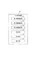
図1には、本実施形態に係る情報取得システム1の構成例を示す。
図1に示すように、情報取得システム1は、カメラ11を搭載したラジコンヘリコプタ(以下、RC撮影装置という。)10、RC撮影装置10の飛行状態を制御する制御装置(以下、RC制御装置という。)30、及び測量装置50を有している。
(Constitution)
FIG. 1 shows a configuration example of an
As shown in FIG. 1, the
図2には、RC撮影装置10の構成例を示す。
図2に示すように、RC撮影装置10は、慣性計測部20、カメラ11、記憶部12、無線通信部13、駆動部14及び駆動制御部15を有している。
慣性計測部20は、RC撮影装置10の飛行状態を計測する。図3には、慣性計測部20の構成例を示す。
In FIG. 2, the structural example of
As shown in FIG. 2, the
The
図3に示すように、慣性計測部20は、3軸ジャイロスコープ21、3軸加速度センサ22、3軸磁気センサ23、気圧センサ24、対地高度測定センサ25、及び水平速度センサ26を有している。ここで、3軸ジャイロスコープ21は、RC撮影装置10の3軸方向(x軸、y軸、z軸)についての角度や角速度を検出する。また、3軸加速度センサ22は、RC撮影装置10の3軸方向についての加速度を検出する。また、3軸磁気センサ23は、3軸方向の検出値を基に、RC撮影装置10の方位角を検出する。また、気圧センサ24は、気圧を検出する。また、対地高度測定センサ25は、RC撮影装置10の飛行高度を検出する。また、水平速度センサ26は、RC撮影装置10の水平方向の飛行速度を検出する。
As shown in FIG. 3, the
カメラ11は、撮影対象となる撮影目標物(情報取得目標物)を撮影する。記憶部12には、カメラ11によって撮影し取得した撮影画像データや慣性計測部20の計測結果が記憶される。
例えば、カメラ11は、地上にある対象物を撮影する場合、図1に示すように、ラジコンヘリコプタのキャビン10aの下部に配置される。このように、カメラ11は、撮影目標物に応じてラジコンヘリコプタへの配置が決定されている。例えば、撮影目標物は、ダム、橋梁等のコンクリート構造物等である。橋梁の裏側を撮影するのであれば、カメラ11は、上方を撮影できるように配置されている。
The
For example, when photographing an object on the ground, the
また、記憶部12は、ROMやRAM、HDD(Hard Disk Drive)等によって構成されている。この記憶部12には、各種プログラムや固定データ等が記憶される。
駆動部14は、メインロータやテールロータ等である。駆動制御部15は、この駆動部14の駆動を制御する。例えば、駆動制御部15は、無線通信部13が受信したRC制御装置30からの駆動制御信号を基に、駆動部14を制御する。この駆動制御部15による制御によって、RC撮影装置10は、予め設定されている飛行経路に沿って飛行する。
The
The
無線通信部13は、RC制御装置30との間で無線通信を行う。例えば、無線通信部13は、RC制御装置30から駆動制御信号を受信する。また、無線通信部13は、撮影画像データや慣性計測部20の計測結果(RC撮影装置10の傾き姿勢、飛行速度、飛行高度等)をRC制御装置30に送信する。
The
RC制御装置30は、RC撮影装置10の飛行を制御するように構成されている。このRC制御装置30は、RC撮影装置10の専用の装置でも良く、パーソナルコンピュータ等のRC撮影装置10を制御することが可能な装置でも良い。
図4には、RC制御装置30の構成例を示す。
The
FIG. 4 shows a configuration example of the
図4に示すように、RC制御装置30は、第1及び第2無線通信部31,32、飛行経路算出部33、演算部34、記憶部35、及び表示部36を有している。
第1無線通信部31は、RC撮影装置10との間で無線通信を行う。例えば、第1無線通信部31は、演算部34が算出した駆動制御信号をRC撮影装置10に送信する。また、第1無線通信部31は、RC撮影装置10からの慣性計測部20の計測結果や撮影画像データを受信する。
As illustrated in FIG. 4, the
The first
第2無線通信部32は、測量装置50との間で通信を行う。例えば、第2無線通信部32は、測量装置50からの測量結果を受信する。
飛行経路算出部33は、RC撮影装置10の飛行経路を算出する。具体的には、飛行経路算出部33は、第2無線通信部32が受信した測量装置50の測量結果を基に、飛行経路を算出する。この飛行経路の算出処理については、後で詳述する。
The second
The flight
演算部34は、各種の演算を行う。例えば、演算部34は、飛行経路算出部33が算出した飛行経路データ及び第1無線通信部31が受信した慣性計測部20の計測結果を基に、RC撮影装置10の飛行状態を制御するための駆動制御信号を算出する。例えば、演算部34は、飛行経路算出部33が算出した飛行経路データと第1無線通信部31が受信した慣性計測部20の計測結果とを比較し、その比較結果を基に、飛行経路上に沿ってRC撮影装置10が飛行する駆動制御信号を算出する。
The
記憶部35には、各種データが記憶される。この記憶部35は、例えば、ROMやRAM、HDD等によって構成されている。例えば、記憶部35には、飛行経路算出部33が算出した飛行経路データが記憶される。また、記憶部35には、第1無線通信部31によって受信したRC撮影装置10からの慣性計測部20の計測結果や撮影画像データが記憶される。
Various data are stored in the
表示部36は、各種表示を行う。例えば、表示部36には、撮影画像データを基に、撮影画像が表示される。
RC制御装置30は、以上のように構成される。
このようなRC制御装置30と通信可能とされている測量装置50は、測量対象物の測量を行う。本実施形態では、測量対象物は、RC撮影装置10や撮影目標物100等である。
The
The
The surveying
測量装置50は、例えば、直交する2つの軸を中心として望遠鏡が回転自在とされているトータルステーション(以下、TSという。)である。ここで、TSとして、手動で操作するマニュアル型TS(すなわちMTS)やモータ駆動によって自動的に動作するモータ駆動型TS(すなわちSTS)等が挙げられる。さらに、モータ駆動型TSには、望遠鏡の視野に入った測量目標物であるターゲット(例えば反射プリズム)を自動的に視準する機能を持つ自動視準TS、又は移動するターゲットを自動的に追尾する機能を有した自動追尾TS等がある。例えば、自動追尾TSでは、一人の作業者による測量を実現できる。
The surveying
図5には、測量装置50の構成例を示す。
図5に示すように、測量装置50は、測距部51、測角部60、水平回転駆動部52、上下回転駆動部53、表示部54、情報入力部55、駆動指令部56、無線通信部57、記憶部58、及び演算部70を有している。
In FIG. 5, the structural example of the surveying
As shown in FIG. 5, the surveying
測距部51は、不図示の望遠鏡を構成の一部として含み、測量対象物までの距離を計測する。
ここで、一般的に、測距方式としては、反射プリズム等の反射体をターゲットして利用したプリズム方式や反射プリズムを利用しないノンプリズム方式等がある。プリズム方式では、例えば、反射プリズムにレーザー光を照射し、その反射光を受光するまでの時間差から距離を計測する。また、ノンプリズム方式は、反射プリズムを利用せず、反射プリズムを設置する必要がないために、プリズム方式と比較して測量の自由度が高くなる。すなわち例えば、ノンプリズム方式では、現場に足を踏み入れることなく離れた場所から測量することが可能になる。例えば、本実施形態では、これら測距方式のうちの何れかを採用して測距部51が構成されている。
The
Here, generally, as a distance measuring method, there are a prism method using a reflector such as a reflecting prism and a non-prism method not using a reflecting prism. In the prism method, for example, the distance is measured from the time difference between irradiating the reflecting prism with laser light and receiving the reflected light. Further, since the non-prism method does not use a reflecting prism and it is not necessary to install a reflecting prism, the degree of freedom in surveying is higher than that of the prism method. That is, for example, in the non-prism method, it is possible to perform surveying from a remote place without entering the site. For example, in the present embodiment, the
測角部60は、水平角検出部61及び高度角検出部62を有している。ここで、水平角検出部61は、測量対象物(本実施形態では、RC撮影装置10や撮影目標物等)の水平角を検出する。また、高度角検出部62は、測量対象物の高度角を検出する。例えば、水平角検出部61は水平角エンコーダであり、高度角検出部62は高度角エンコーダである。
水平回転駆動部52は、望遠鏡を水平方向に回転させる駆動を行う。また、上下回転駆動部53は、望遠鏡を上下方向に回転させる駆動を行う。
The
The horizontal
情報入力部55は、使用者によって操作されて情報が入力される部分である。例えば、情報入力部55は、テンキー等の押しボタンスイッチ等によって構成されている。情報入力部55は、入力された情報を演算部70に出力する。
駆動指令部56には、水平回転及び上下回転それぞれの回転方向を指令するための駆動指令スイッチが設けられている。そして、駆動指令部56は、押下された駆動スイッチに対応した指令信号を演算部70に出力する。
The
The
無線通信部57は、外部機器との間でデータ通信を行うためのインターフェースである。ここで、外部機器として、RC制御装置30の他、パーソナルコンピュータやデータコレクタ(電子野帳)等が挙げられる。本実施形態では、無線通信部57は、RC制御装置30に測量結果を送信する。
The
記憶部58は、ROMやRAM、HDD等によって構成されている。この記憶部58には、各種プログラムや固定データ、演算部70が処理によって取得したデータ等が記憶される。
演算部70は、測量装置50について各種処理を行う。例えば、演算部70は、マイクロコンピュータ及びその周辺回路を備えている。具体的には、図5に示すように、演算部70は、測量制御部71、及び駆動制御部72を有している。
The
The
測量制御部71は、測距部51及び測角部60を制御する。また、測量制御部71は、測距部51及び測角部60の検出値を基に測量値を算出する。そして、測量制御部71は、算出した測量値を、液晶ディスプレイ等である表示部54に表示する。ここで、測量制御部71は、測量値である距離、高度角及び水平角に基づいて、視準した点(すなわちターゲット)の座標値を算出することができる。
The surveying
駆動制御部72には、駆動指令部56からの指令信号が入力される。そして、駆動制御部72は、その指令信号を基に、水平回転駆動部52及び上下回転駆動部53による望遠鏡等を回転させる駆動を制御する。
次に、飛行経路の算出処理について説明する。
A command signal from the
Next, the flight path calculation process will be described.
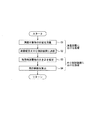
図6には、飛行経路の算出処理の一例のフローチャートを示す。
図6に示すように、先ず、ステップS1では、測量装置50は、測量対象物の位置を測量する。本実施形態では、撮影目標物の周囲に存在する建物等の飛行時障害物を考慮してRC撮影装置10の飛行経路を算出している。そのため、先ず、ステップS1では、測量装置50は、作業者に操作されて、RC撮影装置10の位置、撮影目標物の位置に加えて、飛行時障害物の測量を行う。
FIG. 6 shows a flowchart of an example of a flight path calculation process.
As shown in FIG. 6, first, in step S1, the surveying
図7は、飛行時障害物を測量する一例を説明するための図である。図7に示す例では、飛行時障害物は、道路201の脇のビル202や樹木203となる。なお、飛行時障害物は、本例のような道路脇のビル202や樹木203に限定されないことは言うまでもなく、例えば、道路201に駐車されている自動車等も含む。
FIG. 7 is a diagram for explaining an example of surveying obstacles during flight. In the example shown in FIG. 7, the obstacle during flight is a
このような飛行時障害物がある場合、作業者は、飛行時障害物の外観における予め決められた基準点Aを測量装置50によって測量する。ここで、予め決められた基準点とは、飛行時障害物(例えば、ビル202や樹木203)の大きさ(幅、奥行き、高さ等)を特定するために予め決められている飛行時障害物の外観上の位置である。
When such an obstacle at the time of flight exists, the operator measures the predetermined reference point A in the appearance of the obstacle at the time of flight by the surveying
次に、ステップS2では、測量装置50は、測量結果をRC制御装置30に送信する。ここで、測量結果には、RC撮影装置10の位置、撮影目標物の位置、及び飛行時障害物についての基準点の位置が含まれる。さらに、測量結果には、RC撮影装置10の位置、撮影目標物の位置、及び基準点の位置をそれぞれ判別できる付加情報が含まれる。さらに、測量結果には、基準点について、幅、奥行き、高さのどれを示すかを判別できる付加情報が含まれる。
Next, in step S <b> 2, the surveying
これに対して、ステップS3では、RC制御装置30の飛行経路算出部33は、飛行時障害物の幅、奥行き、及び高さを示す基準点の位置を基に、当該飛行時障害物を3次元の四角柱又は円柱の物体として推定する。さらに、このとき、飛行経路算出部33は、予め設定されている補正値を幅、奥行き、及び高さに加算することで、その3次元の四角柱又は円柱の物体を、本来の飛行時障害物よりも大きい物体として推定する。ここで、補正値は、実験的、経験的、又は理論的に予め設定されている値である。また、補正値は、使用者によって変更可能とされても良い。また、飛行経路算出部33は、高さを示す基準点の情報がない場合、物体の高さを予め設定されている高さに推定しても良い。
On the other hand, in step S3, the flight
ここで、図8には、飛行経路算出部33が推定した四角柱又は円柱の物体(図8に破線で示す物体)の一例を示す。図8に示すように、本実施形態では、ビル202を実際の大きさよりも大きい四角柱の物体202Aとして推定し、樹木203を実際の大きさよりも大きい円柱の物体203Aとして推定している。
Here, FIG. 8 shows an example of a quadrangular or cylindrical object (an object indicated by a broken line in FIG. 8) estimated by the flight
そして、ステップS4では、飛行経路算出部33は、測量装置50によって測量されたRC撮影装置10の最初の位置及び撮影目標物の位置、並びに前記ステップS3で推定した物体を基に、飛行経路を算出する。このとき、飛行経路算出部33は、RC撮影装置10が、前記ステップS3で推定した物体に接触することなく、RC撮影装置10の最初の位置から撮影目標物の上空(すなわち、撮影目標物の撮影可能領域)に当該RC撮影装置10が最短で到達する飛行経路を算出する。
In step S4, the flight
演算部34は、このように飛行経路算出部33が算出した飛行経路データ及び第1無線通信部31が受信した慣性計測部20の計測結果を基に、RC撮影装置10の飛行状態を制御する駆動制御信号を算出する。
The
(動作、作用等)
次に、情報取得システム1における動作、及びその作用等の一例について説明する。
図9には、測量装置50の動作例のフローチャートを示す。
図9に示すように、先ず、ステップS21では、測量装置50は、基準方向を設定する。
(Operation, action, etc.)
Next, an example of the operation in the
In FIG. 9, the flowchart of the operation example of the surveying
As shown in FIG. 9, first, in step S21, the surveying
ここで、図10及び図11には、測量装置50によって基準方向を設定するための測量作業の一例を示す。ここで、図10は、情報取得システム1の側面図である。また、図11は、既知点だけを示す平面図である。
図10に示すように、基準方向を設定するために、作業者は、一方の既知点(機械点)上に測量装置50を設置し、その後、当該測量装置50で他方の既知点を視準する。これによって、図11に示すように、測量装置50は、これら2つの既知点の座標値(x1,y1)、(x2,y2)を基に水平角の基準方向を算出する。
Here, in FIG.10 and FIG.11, an example of the surveying operation | work for setting a reference direction with the surveying
As shown in FIG. 10, in order to set the reference direction, the operator installs the surveying
なお、1つの既知点(機械点)だけしかない場合、測量装置50は、水平角の基準方向として真北に設定する。
次に、ステップS22では、測量装置50は、RC撮影装置10の基準位置(飛行前のRC撮影装置10が地上に置かれている位置)を測定する。
If there is only one known point (machine point), the surveying
Next, in step S22, the surveying
ここで、図12及び図13には、測量装置50によってRC撮影装置10の基準位置を測定するための測量作業の一例を示す。ここで、図12は、情報取得システム1の側面図である。また、図13は、RC撮影装置10の基準位置、及び既知点だけを示す平面図である。
Here, FIGS. 12 and 13 show an example of the surveying work for measuring the reference position of the
図12に示すように、RC撮影装置10の基準位置を測定するために、作業者は、測量装置50によって地上にあるRC撮影装置10を視準する。これによって、図12及び図13に示すように、測量装置50は、当該測量装置50から、地上にあるRC撮影装置10までの斜距離(測量装置50とRC撮影装置10との直線距離)L0、RC撮影装置10についての鉛直角θ0、RC撮影装置10についての水平角a0を算出する。このとき、測量装置50は、前記ステップS21で設定した基準方向を基に水平角a0を算出する。そして、測量装置50は、これら鉛直角θ0等の値を基に、RC撮影装置10の地上での基準位置の座標値(mx,my)を算出する。
As shown in FIG. 12, in order to measure the reference position of the
そして、ステップS23では、測量装置50は、前記ステップS22で算出したRC撮影装置10の基準位置座標値(mx,my)を測量結果としてRC制御装置30に送信する。
次に、ステップS24では、測量装置50は、撮影目標物100の位置を測定する。
In step S23, the surveying
Next, in step S <b> 24, the surveying
ここで、図14及び図15には、測量装置50によって撮影目標物100の位置を測定するための測量作業の一例を示す。ここで、図14は、情報取得システム1の側面図である。また、図15は、RC撮影装置10の基準位置、撮影目標物の位置、及び既知点だけを示す平面図である。
Here, FIGS. 14 and 15 show an example of a surveying work for measuring the position of the photographing
図14に示すように、撮影目標物100の位置を測定するために、作業者は、測量装置50によって、撮影目標物100を視準する。これによって、図15に示すように、測量装置50は、当該測量装置50から撮影目標物100までの斜距離(測量装置50と撮影目標物との直線距離)L1、撮影目標物についての鉛直角θ1、撮影目標物についての水平角a1を算出する。このとき、測量装置50は、前記ステップS21で設定した基準方向を基に水平角a1を算出する。そして、測量装置50は、これら鉛直角θ1等の値を基に、撮影目標物100の位置の座標値(px1,py1)を算出する。
As shown in FIG. 14, in order to measure the position of the
そして、ステップS25では、測量装置50は、前記ステップS24で算出した撮影目標物100の位置座標値(px1,py1)を測量結果としてRC制御装置30に送信する。
次に、ステップS26では、測量装置50は、飛行時障害物の基準点の位置を測定する(前記図7参照)。
In step S25, the surveying
Next, in step S26, the surveying
そして、ステップS27では、測量装置50は、前記ステップS26で算出した飛行時障害物の基準点位置座標値を測量結果としてRC制御装置30に送信する。
以上のように測量装置50が動作する。
図16には、RC制御装置30の動作例のフローチャートを示す。
In step S27, the surveying
The surveying
In FIG. 16, the flowchart of the operation example of
図16に示すように、先ず、ステップS41では、RC制御装置30は、飛行経路作成用の測量結果を測量装置50から全て受信したか否かを判定する。ここで、飛行経路作成用の測量結果とは、前記ステップS23、前記ステップS25、及び前記ステップS27の処理によって測量装置50から送信されてくるRC撮影装置10の基準位置座標値(mx,my)、撮影目標物100の位置座標値(px1,py1)、飛行時障害物の基準点位置座標値等である。
As shown in FIG. 16, first, in step S <b> 41, the
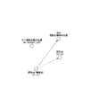
次に、ステップS42では、RC制御装置30は、測量装置50からの飛行経路作成用の測量結果(RC撮影装置10の基準位置座標値(mx,my)等)を基に、RC撮影装置10の飛行経路を算出する。ここで、RC制御装置30は、RC撮影装置10が飛行時障害物に接触することなく撮影可能領域まで飛行できる飛行経路を算出する。このとき、RC制御装置30は、例えば、図17に示すように、RC撮影装置10の基準位置座標値(mx,my)及び撮影目標物の位置座標値(px1,py1)を基に、RC撮影装置10が撮影目標物に移動すべき方位角vと距離Sとを決定する。
Next, in step S42, the
次に、ステップS43では、RC制御装置30は、前記ステップS42で算出した飛行経路を基にRC撮影装置10を制御する。具体的には、RC制御装置30は、飛行経路及び第1無線通信部31が受信したRC撮影装置10からの慣性計測部20の計測結果を基に、駆動制御信号を算出する。そして、RC制御装置30は、算出し駆動制御信号をRC撮影装置10に送信することによって、当該RC撮影装置10を飛行経路に沿って飛行させる。このとき、RC制御装置30は、慣性計測部20の計測結果を用いた慣性航法によって、RC撮影装置10を撮影目標物の上空に移動させる。
Next, in step S43, the
そして、RC制御装置30は、RC撮影装置10が撮影目標物の上空に到達したとき、当該RC撮影装置10をホバリングさせてカメラ11によって撮影目標物を撮影する。そして、RC撮影装置10は、カメラ11によって撮影して取得した撮影画像データを記憶部35に記憶するとともに、無線通信部13によってRC制御装置30にその撮影画像データを送信する。
Then, when the
ここで、慣性航法とは、航空機、船舶、ロケットなどの航法の一つである。この慣性航法は、例えば、ジャイロ、加速度センサ等で航空機等の移動中の加速度を測定し、その測定値の積分演算によって速度や飛行距離を算出して、航空機等が自己の位置を算出しながら所定の航路を航行する方法である。 Here, inertial navigation is one of navigation methods for aircraft, ships, rockets, and the like. In this inertial navigation, for example, the acceleration of a moving aircraft or the like is measured with a gyroscope, an acceleration sensor, etc., and the speed or flight distance is calculated by integrating the measured values, while the aircraft or the like calculates its position. This is a method of navigating a predetermined route.
以上のように、測量装置50は、撮影目標物の位置、RC撮影装置10の位置、及び撮影可能領域(情報取得可能領域)に飛行するRC撮影装置10の飛行の障害になり得る飛行時障害物を測量する。そして、RC制御装置30は、その測量装置50の測量結果を基に飛行経路を算出し、算出した飛行経路及び飛行中のRC撮影装置10の飛行状態を基に、RC撮影装置10の飛行状態を制御してRC撮影装置10を撮影得目標物の上空に飛行させている。
As described above, the surveying
なお、前述の実施形態の説明では、RC撮影装置10は、例えば、無人飛行体を構成する。また、RC制御装置30は、例えば、無人飛行体制御装置を構成する。また、飛行経路算出部33は、例えば、飛行経路算出部に加えて推定部を構成する。また、カメラ11は、例えば、撮影部を構成する。
In the description of the above-described embodiment, the
(本実施形態の変形例等)
本実施形態では、RC撮影装置10は、ラジコンヘリコプタに限らず、他の種類の無人飛行体、例えば気球であっても良い。
また、本実施形態では、情報取得システム1は、カメラ11に限らず、計測装置等の他の手段によって情報取得目標物の情報を取得しても良い。例えば、情報取得システム1は、情報取得目標物の音声を取得しても良い。
(Modifications of this embodiment, etc.)
In the present embodiment, the
In the present embodiment, the
また、本実施形態では、複数の撮影目標物について飛行経路を算出しても良い。この場合、測量装置50は、作業者に操作されて、複数の撮影目標物の位置を測量し、その測量結果をRC制御装置30に送信する。RC制御装置30(具体的には飛行経路算出部33)では、複数の撮影目標物の位置を基に、飛行経路を算出する。
In the present embodiment, the flight path may be calculated for a plurality of shooting targets. In this case, the surveying
この結果、RC撮影装置10は、1つの撮影目標物の撮影を完了すると、次の撮影目標物に向って飛行する。
図18には、次の撮影目標物にRC撮影装置10が飛行する際の処理の一例を示す。
図18に示すように、RC制御装置30は、RC撮影装置10が撮影目標物の撮影を終了すると、RC撮影装置10の位置座標値(mx,my)に当該撮影目標物の位置座標値(px1,py1)を代入し、その後、飛行経路に沿うようにしてRC撮影装置10を次の撮影目標物(座標値(px2,py2))に飛行させる。
As a result, the
FIG. 18 shows an example of processing when the
As illustrated in FIG. 18, when the
また、本実施形態では、RC制御装置30は、測量装置50と一体に構成されていても良い。
また、本実施形態では、飛行経路算出部33が飛行経路を算出する際に推定する飛行時障害物の形は、四角柱や円柱に限定されず、他の形状であっても良い。また、その形状は、使用者によってRC制御装置30等で選択可能とされても良い。例えば、RC制御装置30は、算出した飛行経路を飛行時障害物とともに表示部36に表示することができ、使用者は、表示部36に表示された推定された飛行時障害物の形を選択することができる。そして、RC制御装置30は、飛行時障害物の形が使用者によって選択された場合には、その選択された飛行時障害物の形を基に飛行経路を再度算出する。
In the present embodiment, the
In the present embodiment, the shape of the obstacle at the time of flight estimated when the flight
また、本発明の実施形態を具体的に説明したが、本発明の範囲は、図示され記載された例示的な実施形態に限定されるものではなく、本発明が目的とするものと均等な効果をもたらすすべての実施形態をも含む。さらに、本発明の範囲は、請求項1により画される発明の特徴の組み合わせに限定されるものではなく、すべての開示されたそれぞれの特徴のうち特定の特徴のあらゆる所望する組み合わせによって画されうる。
Further, although the embodiments of the present invention have been specifically described, the scope of the present invention is not limited to the illustrated and described exemplary embodiments, and effects equivalent to those intended by the present invention. All embodiments that provide are also included. Further, the scope of the present invention is not limited to the combination of features of the invention defined by
1 情報取得システム、10 RC撮影装置、11 カメラ、30 RC制御装置、33 飛行経路算出部、50 測量装置
DESCRIPTION OF
Claims (6)
前記測量装置は、前記情報取得目標物の位置、前記無人飛行体の位置、及び前記情報取得可能領域に飛行する前記無人飛行体の飛行の障害になり得る飛行時障害物を測量し、
前記無人飛行体制御装置は、前記測量装置の測量結果を基に、前記無人飛行体が前記飛行時障害物に接触することなく前記情報取得可能領域に飛行できる飛行経路を算出し、算出した飛行経路及び飛行中の前記無人飛行体の飛行状態を基に、前記無人飛行体との無線通信による前記無人飛行体の飛行状態の制御を行い前記無人飛行体を前記情報取得可能領域に飛行させること
を特徴とする情報取得システム。 A surveying device that performs surveying, an unmanned air vehicle that acquires information of an information acquisition target that is a target of information acquisition, and a wireless communication with the unmanned air vehicle to control the flight state of the unmanned air vehicle and thereby the unmanned vehicle An unmanned air vehicle control device for flying an air vehicle to an information acquisition possible region where information of the information acquisition target can be acquired, and an information acquisition system comprising:
The surveying device measures a position of the information acquisition target, a position of the unmanned air vehicle, and an obstacle at the time of flight that may become an obstacle to the flight of the unmanned air vehicle flying in the information acquisition area,
The unmanned aerial vehicle control device calculates a flight path on which the unmanned air vehicle can fly to the information acquisition area without touching the obstacle during the flight based on the survey result of the surveying device, and the calculated flight Based on the route and the flight state of the unmanned air vehicle in flight, the flight state of the unmanned air vehicle is controlled by wireless communication with the unmanned air vehicle, and the unmanned air vehicle is caused to fly to the information acquirable area. An information acquisition system characterized by
前記無人飛行体制御装置は、前記推定部が推定した飛行時障害物を基に、前記飛行経路を算出することを特徴とする請求項1に記載の情報取得システム。 Based on the survey result of the flight obstacle, further has an estimation unit for estimating the flight obstacle larger than the actual size,
The information acquisition system according to claim 1, wherein the unmanned air vehicle control device calculates the flight path based on an obstacle during flight estimated by the estimation unit.
前記無人飛行体制御装置は、前記測量装置が測量した前記飛行前の無人飛行体の位置を基に、前記飛行前の無人飛行体の位置から前記情報取得可能領域までの前記飛行経路を算出することを特徴とする請求項1又は2に記載の情報取得システム。 The surveying device measures the position of the unmanned air vehicle before the flight,
The unmanned air vehicle control device calculates the flight path from the position of the unmanned air vehicle before the flight to the information acquirable area based on the position of the unmanned air vehicle before the flight measured by the surveying device. The information acquisition system according to claim 1, wherein the information acquisition system is an information acquisition system.
前記情報取得目標物の位置、前記無人飛行体の位置、及び前記情報取得可能領域に飛行する前記無人飛行体の飛行の障害になり得る飛行時障害物についての前記測量装置の測量結果を基に、前記無人飛行体が前記飛行時障害物に接触することなく前記情報取得可能領域に飛行できる飛行経路を算出する飛行経路算出部と、
前記飛行経路算出部が算出した飛行経路及び飛行中の前記無人飛行体の飛行状態を基に、前記無人飛行体との無線通信による前記無人飛行体の飛行状態の制御を行い前記無人飛行体を前記情報取得可能領域に飛行させる制御部と、
を有する無人飛行体制御装置。 Information on the information acquisition target can be acquired from the unmanned air vehicle by controlling the flight state of the unmanned air vehicle by wireless communication with the unmanned air vehicle that acquires information on the information acquisition target that is the information acquisition target. An unmanned air vehicle control device for flying in an information acquisition area,
Based on the survey results of the surveying device on the position of the information acquisition target, the position of the unmanned air vehicle, and the flight obstacle that may be an obstacle to the flight of the unmanned air vehicle flying in the information acquisition area A flight path calculation unit that calculates a flight path through which the unmanned air vehicle can fly to the information acquisition area without touching the obstacle during flight;
Based on the flight path calculated by the flight path calculation unit and the flight state of the unmanned air vehicle in flight, the flight state of the unmanned air vehicle is controlled by wireless communication with the unmanned air vehicle. A control unit that flies to the information acquisition area;
An unmanned air vehicle control device.
前記飛行経路算出部は、前記推定部が推定した前記飛行時障害物を基に、前記飛行経路を算出することを特徴とする請求項5に記載の無人飛行体制御装置。 Based on the survey result of the flight obstacle, further has an estimation unit for estimating the flight obstacle larger than the actual size,
The unmanned air vehicle control apparatus according to claim 5, wherein the flight path calculation unit calculates the flight path based on the flight obstacle estimated by the estimation unit.
Priority Applications (1)
| Application Number | Priority Date | Filing Date | Title |
|---|---|---|---|
| JP2013259169A JP6302660B2 (en) | 2013-12-16 | 2013-12-16 | Information acquisition system, unmanned air vehicle control device |
Applications Claiming Priority (1)
| Application Number | Priority Date | Filing Date | Title |
|---|---|---|---|
| JP2013259169A JP6302660B2 (en) | 2013-12-16 | 2013-12-16 | Information acquisition system, unmanned air vehicle control device |
Publications (2)
| Publication Number | Publication Date |
|---|---|
| JP2015113100A true JP2015113100A (en) | 2015-06-22 |
| JP6302660B2 JP6302660B2 (en) | 2018-03-28 |
Family
ID=53527280
Family Applications (1)
| Application Number | Title | Priority Date | Filing Date |
|---|---|---|---|
| JP2013259169A Active JP6302660B2 (en) | 2013-12-16 | 2013-12-16 | Information acquisition system, unmanned air vehicle control device |
Country Status (1)
| Country | Link |
|---|---|
| JP (1) | JP6302660B2 (en) |
Cited By (11)
| Publication number | Priority date | Publication date | Assignee | Title |
|---|---|---|---|---|
| JP2017144986A (en) * | 2015-10-14 | 2017-08-24 | パナソニック インテレクチュアル プロパティ コーポレーション オブ アメリカPanasonic Intellectual Property Corporation of America | Unmanned air vehicle and flight control method |
| JP2017182454A (en) * | 2016-03-30 | 2017-10-05 | セコム株式会社 | Monitoring system and object detection device |
| JP2017182453A (en) * | 2016-03-30 | 2017-10-05 | セコム株式会社 | Monitoring system and object detection device |
| KR20190005079A (en) * | 2017-07-05 | 2019-01-15 | 이현주 | Apparatus for removing fog |
| JPWO2017170651A1 (en) * | 2016-03-31 | 2019-03-07 | 住友重機械工業株式会社 | Work management system for construction machine and construction machine |
| JP2019133704A (en) * | 2015-12-28 | 2019-08-08 | Kddi株式会社 | Flying object and flight permitted airspace setting device |
| US10558218B2 (en) | 2016-01-28 | 2020-02-11 | Fujitsu Ten Limited | Vehicle surroundings monitoring apparatus, monitoring system, remote monitoring apparatus, and monitoring method |
| WO2020071305A1 (en) * | 2018-10-03 | 2020-04-09 | 株式会社ナイルワークス | Driving route generating device, driving route generating method, driving route generating program, and drone |
| JP2021008269A (en) * | 2016-08-16 | 2021-01-28 | 本郷飛行機株式会社 | Information processing system |
| WO2023162953A1 (en) * | 2022-02-25 | 2023-08-31 | 株式会社Spiral | Control system for flying vehicle |
| WO2023238639A1 (en) * | 2022-06-10 | 2023-12-14 | ソニーグループ株式会社 | Information processing method, information processing device, and program |
Citations (6)
| Publication number | Priority date | Publication date | Assignee | Title |
|---|---|---|---|---|
| JP2002277544A (en) * | 2001-03-21 | 2002-09-25 | Toshiba Corp | Airport runway monitoring device |
| JP2008203097A (en) * | 2007-02-20 | 2008-09-04 | Toshiba Corp | Supporting device for aerial photography plan |
| JP2010095246A (en) * | 2008-10-20 | 2010-04-30 | Honeywell Internatl Inc | System for navigation of unmanned aerial vehicle and method used for the same |
| CA2833184A1 (en) * | 2011-04-14 | 2012-10-18 | Hexagon Technology Center Gmbh | Geodetic marking system for marking target points |
| CA2832956A1 (en) * | 2011-04-14 | 2012-10-18 | Hexagon Technology Center Gmbh | System and method for controlling an unmanned aerial vehicle |
| JP2015001450A (en) * | 2013-06-14 | 2015-01-05 | 株式会社トプコン | Air vehicle guidance system, and air vehicle guidance method |
-
2013
- 2013-12-16 JP JP2013259169A patent/JP6302660B2/en active Active
Patent Citations (6)
| Publication number | Priority date | Publication date | Assignee | Title |
|---|---|---|---|---|
| JP2002277544A (en) * | 2001-03-21 | 2002-09-25 | Toshiba Corp | Airport runway monitoring device |
| JP2008203097A (en) * | 2007-02-20 | 2008-09-04 | Toshiba Corp | Supporting device for aerial photography plan |
| JP2010095246A (en) * | 2008-10-20 | 2010-04-30 | Honeywell Internatl Inc | System for navigation of unmanned aerial vehicle and method used for the same |
| CA2833184A1 (en) * | 2011-04-14 | 2012-10-18 | Hexagon Technology Center Gmbh | Geodetic marking system for marking target points |
| CA2832956A1 (en) * | 2011-04-14 | 2012-10-18 | Hexagon Technology Center Gmbh | System and method for controlling an unmanned aerial vehicle |
| JP2015001450A (en) * | 2013-06-14 | 2015-01-05 | 株式会社トプコン | Air vehicle guidance system, and air vehicle guidance method |
Cited By (21)
| Publication number | Priority date | Publication date | Assignee | Title |
|---|---|---|---|---|
| JP2017144986A (en) * | 2015-10-14 | 2017-08-24 | パナソニック インテレクチュアル プロパティ コーポレーション オブ アメリカPanasonic Intellectual Property Corporation of America | Unmanned air vehicle and flight control method |
| US11373541B2 (en) | 2015-12-28 | 2022-06-28 | Kddi Corporation | Flight permitted airspace setting device and method |
| US10720067B2 (en) | 2015-12-28 | 2020-07-21 | Kddi Corporation | Unmanned flight vehicle having rotor, motor rotating the rotor and control device |
| JP2019133704A (en) * | 2015-12-28 | 2019-08-08 | Kddi株式会社 | Flying object and flight permitted airspace setting device |
| US10558218B2 (en) | 2016-01-28 | 2020-02-11 | Fujitsu Ten Limited | Vehicle surroundings monitoring apparatus, monitoring system, remote monitoring apparatus, and monitoring method |
| JP2017182453A (en) * | 2016-03-30 | 2017-10-05 | セコム株式会社 | Monitoring system and object detection device |
| JP2017182454A (en) * | 2016-03-30 | 2017-10-05 | セコム株式会社 | Monitoring system and object detection device |
| JP7032308B2 (en) | 2016-03-31 | 2022-03-08 | 住友重機械工業株式会社 | Work management system for construction machinery and construction machinery |
| US11092976B2 (en) | 2016-03-31 | 2021-08-17 | Sumitomo Heavy Industries, Ltd. | Construction machine work management system and construction machine |
| JPWO2017170651A1 (en) * | 2016-03-31 | 2019-03-07 | 住友重機械工業株式会社 | Work management system for construction machine and construction machine |
| JP7029195B2 (en) | 2016-08-16 | 2022-03-03 | 本郷飛行機株式会社 | Information processing system |
| JP2021008269A (en) * | 2016-08-16 | 2021-01-28 | 本郷飛行機株式会社 | Information processing system |
| US11671888B2 (en) | 2016-08-16 | 2023-06-06 | Hongo Aerospace Inc. | Information processing system |
| KR102120902B1 (en) * | 2017-07-05 | 2020-06-17 | 이현주 | Apparatus for removing fog |
| KR20190005079A (en) * | 2017-07-05 | 2019-01-15 | 이현주 | Apparatus for removing fog |
| WO2020071305A1 (en) * | 2018-10-03 | 2020-04-09 | 株式会社ナイルワークス | Driving route generating device, driving route generating method, driving route generating program, and drone |
| JPWO2020071305A1 (en) * | 2018-10-03 | 2021-09-24 | 株式会社ナイルワークス | Driving route generator, driving route generation method, driving route generation program, and drone |
| JP7270265B2 (en) | 2018-10-03 | 2023-05-10 | 株式会社ナイルワークス | Driving route generation device, driving route generation method, driving route generation program, and drone |
| WO2023162953A1 (en) * | 2022-02-25 | 2023-08-31 | 株式会社Spiral | Control system for flying vehicle |
| JP7399534B1 (en) | 2022-02-25 | 2023-12-18 | 株式会社Spiral | Aircraft control system |
| WO2023238639A1 (en) * | 2022-06-10 | 2023-12-14 | ソニーグループ株式会社 | Information processing method, information processing device, and program |
Also Published As
| Publication number | Publication date |
|---|---|
| JP6302660B2 (en) | 2018-03-28 |
Similar Documents
| Publication | Publication Date | Title |
|---|---|---|
| JP6302660B2 (en) | Information acquisition system, unmanned air vehicle control device | |
| JP5882951B2 (en) | Aircraft guidance system and aircraft guidance method | |
| JP6693765B2 (en) | Flight object tracking method and flight object guidance system | |
| JP7077013B2 (en) | 3D information processing unit, device equipped with 3D information processing unit, unmanned aerial vehicle, notification device, moving object control method using 3D information processing unit, and program for moving object control processing | |
| JP6326237B2 (en) | Measuring system | |
| JP6691721B2 (en) | Flight planning method and flight guidance system | |
| EP2869024B1 (en) | Three-dimensional measuring method and surveying system | |
| JP6671375B2 (en) | How to fly a drone | |
| US9158305B2 (en) | Remote control system | |
| JP5854348B2 (en) | Remote control method and remote control system | |
| JP6812667B2 (en) | Unmanned aerial vehicle control system, unmanned aerial vehicle control method and unmanned aerial vehicle | |
| JP6001914B2 (en) | Target position specifying device, target position specifying system, and target position specifying method | |
| US20210229810A1 (en) | Information processing device, flight control method, and flight control system | |
| JP2022057277A (en) | Surveying system | |
| JP6570344B2 (en) | Route generation method and system | |
| JP2020126663A (en) | Flight plan creation method and flying body guidance system | |
| JP7031997B2 (en) | Aircraft system, air vehicle, position measurement method, program | |
| JP2022147973A (en) | Attitude detection device and attitude control system of flying object | |
| JP2019219206A (en) | Measurement system | |
| JP2019168229A (en) | Gauge marking system using uav | |
| JP2023070120A (en) | Autonomous flight control method, autonomous flight control apparatus and autonomous flight control system | |
| JP2022067500A (en) | Survey system | |
| JP2022143314A (en) | Surveying system, method for surveying, and surveying program | |
| CA2852891A1 (en) | Flight system |
Legal Events
| Date | Code | Title | Description |
|---|---|---|---|
| A625 | Written request for application examination (by other person) |
Free format text: JAPANESE INTERMEDIATE CODE: A625 Effective date: 20161003 |
|
| A977 | Report on retrieval |
Free format text: JAPANESE INTERMEDIATE CODE: A971007 Effective date: 20170626 |
|
| A131 | Notification of reasons for refusal |
Free format text: JAPANESE INTERMEDIATE CODE: A131 Effective date: 20170801 |
|
| A521 | Request for written amendment filed |
Free format text: JAPANESE INTERMEDIATE CODE: A523 Effective date: 20170907 |
|
| TRDD | Decision of grant or rejection written | ||
| A01 | Written decision to grant a patent or to grant a registration (utility model) |
Free format text: JAPANESE INTERMEDIATE CODE: A01 Effective date: 20180206 |
|
| A61 | First payment of annual fees (during grant procedure) |
Free format text: JAPANESE INTERMEDIATE CODE: A61 Effective date: 20180305 |
|
| R150 | Certificate of patent or registration of utility model |
Ref document number: 6302660 Country of ref document: JP Free format text: JAPANESE INTERMEDIATE CODE: R150 |
|
| R250 | Receipt of annual fees |
Free format text: JAPANESE INTERMEDIATE CODE: R250 |
|
| R250 | Receipt of annual fees |
Free format text: JAPANESE INTERMEDIATE CODE: R250 |
|
| R250 | Receipt of annual fees |
Free format text: JAPANESE INTERMEDIATE CODE: R250 |
|
| R250 | Receipt of annual fees |
Free format text: JAPANESE INTERMEDIATE CODE: R250 |