JP2015110902A - Connection structure of backfilling agent supply pipe - Google Patents
Connection structure of backfilling agent supply pipe Download PDFInfo
- Publication number
- JP2015110902A JP2015110902A JP2015025003A JP2015025003A JP2015110902A JP 2015110902 A JP2015110902 A JP 2015110902A JP 2015025003 A JP2015025003 A JP 2015025003A JP 2015025003 A JP2015025003 A JP 2015025003A JP 2015110902 A JP2015110902 A JP 2015110902A
- Authority
- JP
- Japan
- Prior art keywords
- agent supply
- backfilling agent
- backfilling
- supply pipe
- pile
- Prior art date
- Legal status (The legal status is an assumption and is not a legal conclusion. Google has not performed a legal analysis and makes no representation as to the accuracy of the status listed.)
- Granted
Links
Images


Abstract
Description
本発明は、建築物を解体した後に地中に残った既設杭の引抜工程と、杭を引き抜いた後に流動性を備えた埋戻剤を充填する埋戻工程とを有する杭抜埋戻工法、及び当該杭抜埋戻工法に用いる埋戻剤供給管の接続構造に関する。 The present invention is a pile unloading method having a pulling process of an existing pile remaining in the ground after dismantling the building, and a refilling process of filling a backfilling agent having fluidity after pulling the pile, And a connection structure of a backfilling agent supply pipe used in the pile unfilling method.
従来、建築物を解体した後に地中に残った既設杭を引き抜いて埋め戻す作業を行う場合には、杭を引き抜く作業を行った後に、その土地質に合った埋戻剤を調製して、杭を引き抜いてできた穴に埋戻剤を充填する処理を行っている。 Conventionally, when performing the work of pulling out the existing piles remaining in the ground after dismantling the building and backfilling, after performing the work of pulling out the piles, prepare a backfilling agent suitable for the land quality, The hole filling the hole made by pulling out the pile is filled with backfilling agent.
しかし、杭を引き抜いてできた穴には周囲の土砂が崩れて溜まっていたり、掘削に用いた水や地下水が溜まっていたりするため、単に穴の開口上部から埋戻剤を投入しても穴の内部に十分に行き渡らないことが多い。このように、埋め戻した穴の内部に埋戻剤の充填むらや空隙ができてしまうと地盤変状を生ずることになる。この地盤変状が生じている場所に新たに杭打ちを行うと、掘削する杭打ち用の穴が斜行してしまったり、圧入する杭が斜行してしまうなどの不具合を生ずることになる。 However, since the surrounding earth and sand collapses and accumulates in the holes made by pulling out the piles, and the water and groundwater used for excavation are accumulated, even if a backfill agent is introduced from the upper part of the hole opening, Often does not reach the interior of the room. In this way, if uneven filling or voids of the backfilling agent are formed inside the backfilled hole, ground deformation will occur. If new pile driving is performed in a place where this ground deformation has occurred, the holes for drilling piles will be skewed or the piles to be pressed will be skewed. .
このような杭抜き後の地盤変状を防止するための鋼管杭の杭抜き工法が、特開2009−256999号公報(特許文献1)に開示されている。 Japanese Patent Application Laid-Open No. 2009-256999 (Patent Document 1) discloses a steel pipe pile pile removal method for preventing such ground deformation after pile removal.
特許文献1に記載されている鋼管杭の引き抜き工法では、先ず地中にある既設中空杭の杭内周部に詰め固められている土砂などの充填材を、スパイラルオーガ又は羽根付き掘削ロッドなどを用いて中堀り攪拌して揉み解す攪拌工程と、既設中空杭の外周面に沿って掘削機能を有するケーシングを挿入することで杭外周面を掘削するケーシング挿入工程と、既設中空杭内から排出された充填材を地中に開いた杭抜き孔内に充填しながら既設中空杭を地中から引き抜く杭抜き工程とを具備している。 In the steel pipe pile drawing method described in Patent Document 1, first, a filler such as earth and sand packed in the inner periphery of an existing hollow pile in the ground, a spiral auger or a bladed drilling rod, etc. Using the agitating process to squeeze and squeeze through the middle drilling, the casing insertion process to excavate the outer peripheral surface of the pile by inserting a casing having a drilling function along the outer peripheral surface of the existing hollow pile, and discharged from the existing hollow pile A pile removing step of drawing an existing hollow pile from the ground while filling the pile filling hole opened in the ground.
特許文献1に記載されている鋼管杭の引き抜き工法によれば、既設中空杭内から充填材を排出しながら既設中空杭を引き抜くので、充填材を排出したぶん杭重量を軽減して杭抜き作業を容易にすることができるとともに、杭抜き穴の充填処理を容易にして地盤変状を防止することができるとしている。 According to the steel pipe pile drawing method described in Patent Document 1, the existing hollow pile is pulled out while discharging the filler from the existing hollow pile, so that the pile weight is reduced by reducing the weight of the pile that has discharged the filler. In addition, it is possible to facilitate the filling process of the pile hole and to prevent ground deformation.
特許文献1に記載されている鋼管杭の引き抜き工法では、既設中空杭の外周面に沿ってケーシングを用いて掘削する際に、ケーシング先端からジェット水又は泥水を吐出させながら掘削する旨の記載(例えば、段落番号[0020])があり、この吐出したジェット水又は泥水により既設中空杭内の充填材も流動性を有している可能性がある。 In the steel pipe pile drawing method described in Patent Document 1, when excavating using a casing along the outer peripheral surface of an existing hollow pile, a description of excavating while discharging jet water or mud from the tip of the casing ( For example, there is a paragraph number [0020]), and the filler in the existing hollow pile may have fluidity due to the jet water or mud water discharged.
しかし、ジェット水又は泥水の吐出は、ケーシングの回転による掘削抵抗を減少させる目的で行っているものであり、流動化した充填材も周囲の地盤性状に合わせて調製したものではないので、埋め戻した後に地盤変状が生じている可能性が高い。したがって、この地盤変状が生じている場所に新たに杭打ちを行うと、杭が斜行してしまうなどの不具合を生ずることになる。 However, jet water or muddy water is discharged for the purpose of reducing excavation resistance due to rotation of the casing, and the fluidized filler is not prepared according to the surrounding ground properties. There is a high possibility that ground deformation has occurred. Therefore, when a pile is newly struck in a place where the ground deformation has occurred, problems such as the pile skewing occur.
また、特許文献1に記載されている鋼管杭の引き抜き工法は、鋼管杭などの中空杭の引抜きに限定して用いることができるものであり、他のPC杭(プレストコンクリート杭)、PHC杭(プレストレスト高強度コンクリート杭)、BT杭(ボックスタイプ杭)、摩擦杭などの既成の杭や、ED杭(アースドリル杭)、リバース杭、ペデスタル杭等の場所打ちした杭の引抜きに用いることができないという不具合がある。 Moreover, the drawing method of the steel pipe pile described in patent document 1 can be limited and used for drawing of hollow piles, such as a steel pipe pile, and other PC pile (pressed concrete pile), PHC pile ( Pre-stressed high-strength concrete piles), BT piles (box-type piles), friction piles, etc., and ED piles (earth drill piles), reverse piles, pedestal piles, etc. There is a problem that.
また、杭を抜いた後の杭抜き穴の底部には、掘削時に用いた潤滑用の水や泥、更に地下水や崩れた土砂等が溜まっている。この状態で杭抜き穴の地表部分から埋戻剤を投入しても、内部に溜まっている水や土砂と混ざった状態で固化してしまうため、地盤変状を生じてしまう可能性がある。杭抜き穴に埋戻剤を均一かつ確実に充填させるためには、埋戻剤を吐出する埋戻剤供給管の吐出口を杭抜き穴の底部付近まで到達させておき、埋戻剤供給管の吐出口から埋戻剤を吐出させて、埋め戻し穴の内部に溜まっている水や土砂を浮かせてゆきながら充填する必要がある。 In addition, lubrication water and mud used at the time of excavation, ground water, collapsed earth and sand, and the like are collected at the bottom of the pile hole after the pile is extracted. In this state, even if a backfilling agent is introduced from the ground surface portion of the pile hole, it is solidified in a state of being mixed with water or earth and sand accumulated in the inside, so that there is a possibility of causing ground deformation. In order to fill the pile removal hole uniformly and reliably, the discharge port of the backfilling agent supply pipe that discharges the backfilling agent is made to reach the bottom of the pile removal hole, and the backfilling agent supply pipe It is necessary to discharge the backfilling agent from the discharge port and fill the water and the earth and sand accumulated in the backfilling hole while floating.
既設杭の長さが数メートル以上である場合に、埋戻剤の吐出口を杭抜き穴の底部付近まで到達させておくためには、埋戻剤供給管を複数本接続する必要がある。しかし、埋戻剤供給管を掘削穴に挿入する際に、埋戻剤供給管の接続部が掘削穴の側壁と接触するなどして、埋戻剤供給管同士の接続が外れてしまう場合がある。特に、埋戻剤供給管を挿入する杭抜き穴が狭い場合や、杭抜き穴の深さが深い場合には、埋戻剤供給管同士の接続が外れてしまう可能性が高くなる。 In the case where the length of the existing pile is several meters or more, it is necessary to connect a plurality of backfilling agent supply pipes in order to make the discharge port of the backfilling agent reach the vicinity of the bottom of the pile removal hole. However, when the backfilling agent supply pipe is inserted into the excavation hole, the connecting part of the backfilling agent supply pipe may come into contact with the side wall of the excavation hole, and the connection between the backfilling agent supply pipes may be disconnected. is there. In particular, when the pile hole for inserting the backfill agent supply pipe is narrow or when the depth of the pile hole is deep, there is a high possibility that the connection between the backfill agent supply pipes is disconnected.
図24〜図27に、従来の埋戻剤供給管の接続構造及びその方法を示す。 24 to 27 show a conventional backfilling agent supply pipe connection structure and method.
図24は、長尺の第1埋戻剤供給管981及び第2埋戻剤供給管982における従来の接続部980の構造及び係合保持管990の形状を説明する図である。図25は、第1埋戻剤供給管981と第2埋戻剤供給管982とを接続部980にて接続して接続部980の外周部に係合保持管990を被せる前の状態を示す図である。図26は、第1埋戻剤供給管981と第2埋戻剤供給管982とを接続部980にて接続して接続部980の外周部に従来の係合保持管990を被せ、当該係合保持管990が第2埋戻剤供給管982の軸方向にずれないように針金992で固定した状態を示す図である。図27は、第1埋戻剤供給管981と第2埋戻剤供給管982とを接続部980にて接続して接続部980の外周部に従来の係合保持管990を被せ、当該係合保持管990が第2埋戻剤供給管982の軸方向にずれないようにガムテープ994で固定した状態を示す図である。
FIG. 24 is a view for explaining the structure of the conventional connecting
図24に示すように、長尺の第1埋戻剤供給管981の端部には、半円筒形状に切除して形成した半円筒部983と、当該半円筒部983の先端内筒面に係合用の内接円筒管985を取着した内接円筒管突出部986とを有する接続部980が形成されている。また、同様に、長尺の第2埋戻剤供給管982の端部には、半円筒形状に切除して形成した半円筒部983と、当該半円筒部983の先端内筒面に係合用の内接円筒管985を取着した内接円筒管突出部986とを有する接続部980が形成されている。
As shown in FIG. 24, the end portion of the long first backfilling
第1埋戻剤供給管981と第2埋戻剤供給管982とを接続する場合には、先ず第2埋戻剤供給管982に係合保持管990を通しておく。次に、第1埋戻剤供給管981及び第2埋戻剤供給管982の軸を平行にずらして、それぞれの埋戻剤供給管の接続部980を向かい合わせた状態から、第1埋戻剤供給管981の接続部980に形成した半円筒部983の内部に第2埋戻剤供給管982の接続部980の内接円筒管突出部986を嵌入すると同時に、第2埋戻剤供給管982の接続部980に形成した半円筒部983の内部に第1埋戻剤供給管981の接続部980の内接円筒管突出部を嵌入して第1埋戻剤供給管981及び第2埋戻剤供給管982の軸を一致させる(図25参照)。
When connecting the first backfilling
その後に、第1埋戻剤供給管981及び第2埋戻剤供給管982の接続部980の外周部に係合保持管990を移動させて被せることによって、第1埋戻剤供給管981と第2埋戻剤供給管982との係合状態を拘束しておくことができる。
Thereafter, the
しかし、接続部980の外周部に係合保持管990を被せた状態のまま、第1埋戻剤供給管981及び第2埋戻剤供給管982を掘削穴に挿入してゆくと、係合保持管990が掘削穴の側壁と接触するなどして係合保持管990が上方にずれて接続部980から外れてしまい、第1埋戻剤供給管981と第2埋戻剤供給管982との接続が外れて分離してしまう不具合が多発する。
However, if the first backfilling
そこで従来は、図26に示すように、係合保持管990が上方にずれて接続部980から外れてしまうことを防止するために、針金992を係合保持管990上方の第2埋戻剤供給管982に巻き付けたり、図27に示すようにガムテープ994を用いて係合保持管990と第2埋戻剤供給管982とを固定するように巻き付けていた。
Therefore, conventionally, as shown in FIG. 26, in order to prevent the
しかし、図26及び図27に示すようにして係合保持管990の固定を試みても、第1埋戻剤供給管981及び第2埋戻剤供給管982を杭抜き穴に挿入してゆく際に、係合保持管990が掘削穴の側壁と接触するなどして係合保持管990が上方にずれて接続部980から外れてしまい、第1埋戻剤供給管981と第2埋戻剤供給管982との接続が外れて分離してしまう不具合が発生していた。
However, even if the
本発明は、上記課題に鑑みなされたものであり、建築物を解体した後に地中に残った既設杭を引き抜いて埋め戻した後の地盤変状を減少させるとともに、工期を短縮することが可能な杭抜埋戻工法と、当該杭抜埋戻工法に用いる埋戻剤供給管の接続構造を提供することを目的としている。 The present invention has been made in view of the above problems, and it is possible to reduce ground deformation after pulling out an existing pile remaining in the ground after dismantling the building and backfilling it, and to shorten the construction period. An object of the present invention is to provide a connecting structure for a pile unfilling method and a backfilling agent supply pipe used for the pile unfilling method.
また、本発明は、埋戻剤供給管を杭抜き穴に挿入する際においても埋戻剤供給管同士がその接続部において外れにくい埋戻剤供給管の接続構造を提供することを目定としている。 Further, the present invention provides a connecting structure for backfilling agent supply pipes that is difficult for the backfilling agent supply pipes to come off at their connecting portions even when the backfilling agent supply pipe is inserted into the pile hole. Yes.
上記課題を解決するために、本発明に係る杭抜埋戻工法は、既設杭の外周面に沿って掘削用ケーシングを用いて掘削する外周掘削工程と、前記掘削した既設杭の外周部に、流動性を有する埋戻剤を供給する埋戻剤供給管を配設する埋戻剤供給管配設工程と、前記埋戻剤供給管を介して前記埋戻剤を供給しながら前記既設杭を引き上げることによって前記埋戻剤を杭抜き穴に充填する既設杭引上埋戻工程とを有することを特徴とする。 In order to solve the above-described problem, the pile refilling method according to the present invention includes an outer excavation step of excavating using an excavation casing along an outer peripheral surface of an existing pile, and an outer peripheral portion of the excavated existing pile. A backfill agent supply pipe disposing step of disposing a backfill agent supply pipe for supplying a backfill agent having fluidity; and supplying the backfill agent via the backfill agent supply pipe An existing pile pulling backfilling step of filling the pile punching hole with the backfilling agent by pulling up.
この発明によれば、引き抜く既設杭の外周部を掘削し、その掘削した既設杭の外周部に埋戻剤供給管を配設して、埋戻剤を供給しながら既設杭を引き上げることによって、杭抜き穴に空隙が生じることなく、杭抜き穴に直接埋戻剤を充填することができる。これにより、杭抜き穴に埋戻剤をより確実に充填することが可能となり、既設杭を引き抜いて埋め戻した後の地盤変状を減少させることができる。また本発明では、既設杭の引抜き作業と埋戻剤の充填作業とを同時に行うので、杭抜き埋戻し作業の工期を短縮することができる。 According to this invention, by excavating the outer peripheral portion of the existing pile to be pulled out, disposing the backfilling agent supply pipe on the outer peripheral portion of the excavated existing pile, and pulling up the existing pile while supplying the backfilling agent, The backfilling agent can be directly filled in the pile punching hole without generating a void in the pile punching hole. Thereby, it becomes possible to more reliably fill the pile punching hole with the backfilling agent, and the ground deformation after the existing pile is pulled out and backfilled can be reduced. Moreover, in this invention, since the extraction operation | work of an existing pile and the filling operation | work of a backfill agent are performed simultaneously, the construction period of a pile extraction backfilling operation | work can be shortened.
上記本発明に係る杭抜埋戻工法は、前記杭抜埋戻工法における既設杭の既設杭引上埋戻工程において、前記埋戻剤の供給及び前記既設杭の引き上げと併せて前記埋戻剤供給管を引き上げることを特徴とする。 The pile unfilling method according to the present invention is the above-mentioned backfilling agent in the existing pile pulling backfilling process of the existing pile in the pile unfilling method together with the supply of the backfilling agent and the lifting of the existing pile. It is characterized by pulling up the supply pipe.
この発明によれば、埋戻剤の供給及び前記既設杭の引き上げと併せて埋戻剤供給管を引き上げることによって、固化が速い埋戻剤を用いる場合や、既設杭が長いために引抜きに時間がかかる場合においても、埋戻剤の充填処理をより確実に行って、埋め戻した後の地盤変状を減少させることができる。 According to this invention, when the backfilling agent supply pipe is pulled up together with the supply of the backfilling agent and the backfilling agent supply pipe is pulled up, when the backfilling agent that is quickly solidified is used or when the existing pile is long, it takes time to pull out. Even in such a case, the filling process of the backfilling agent can be performed more reliably, and the ground deformation after the backfilling can be reduced.
上記課題を解決するために本発明に係る埋戻剤供給管の接続構造は、長尺管の端部を半円筒形状に切除して形成した半円筒部と当該半円筒部の先端内筒面に係合用の内接円筒管を取着した内接円筒管突出部とを有する接続部がそれぞれ形成された第1及び第2の埋戻剤供給管と、前記第1及び第2の埋戻剤供給管の軸を平行にずらして前記それぞれの接続部を向かい合わせた状態から、前記第1の埋戻剤供給管接続部に形成した半円筒部の内部に前記第2の埋戻剤供給管接続部の内接円筒管突出部を嵌入すると同時に、前記第2の埋戻剤供給管接続部に形成した半円筒部の内部に前記第1の埋戻剤供給管接続部の内接円筒管突出部を嵌入して前記第1及び第2の埋戻剤供給管の軸を一致させた後に、前記第1及び第2の埋戻剤供給管接続部の外周部に被せることによって前記第1及び第2の埋戻剤供給管の係合状態を拘束する係合保持管と、を備える埋戻剤供給管の接続構造において、
前記第1の埋戻剤供給管接続部における外周部の一部に突出させたロック凸部と、前記ロック凸部を通過させることが可能な、前記係合保持管に開設した溝であって、一端に前記ロック凸部の入出を可能にする導入部を有すると共に少なくとも当該係合保持管の円周方向に開設した溝を有する円周溝と、当該円周溝から当該係合保持管の軸方向に向けて開設した回動防止溝と、を備えることを特徴とする。
In order to solve the above-described problems, the connecting structure of the backfilling agent supply pipe according to the present invention includes a semi-cylindrical part formed by cutting an end part of a long pipe into a semi-cylindrical shape, and a tip inner cylindrical surface of the semi-cylindrical part First and second backfilling agent supply pipes each having a connecting portion having an inscribed cylindrical tube projection portion with an inscribed cylindrical tube attached thereto, and the first and second backfilling portions. Supply of the second backfilling agent into a semi-cylindrical portion formed in the first backfilling agent supply pipe connecting portion from a state in which the axes of the agent supply pipes are shifted in parallel and the respective connecting portions face each other. An inscribed cylinder of the first backfilling agent supply pipe connecting part is inserted into a semicylindrical part formed in the second backfilling agent supply pipe connecting part at the same time when the inscribed cylindrical pipe projecting part of the pipe connecting part is inserted. After inserting the pipe protrusion and aligning the axes of the first and second backfilling agent supply pipes, the first and second backfilling agent supply pipe connecting parts In the connection structure of refilling agent supply pipe and a engagement holding tube for restraining the engagement state of the first and second refilling agent feed pipe by covering the periphery,
A locking protrusion protruding from a part of the outer peripheral portion of the first backfilling agent supply pipe connecting portion, and a groove formed in the engagement holding pipe capable of passing the locking protrusion. A circumferential groove having an introduction portion that allows the lock protrusion to enter and exit at one end, and at least a groove opened in a circumferential direction of the engagement holding tube, and the engagement holding tube from the circumferential groove. And a rotation preventing groove that is opened in the axial direction.
この発明によれば、第1及び第2の埋戻剤供給管を接続部にて接続して第1及び第2の埋戻剤供給管の軸を一致させ、当該接続部の外周部に係合保持管を被せる工程において、先ずロック凸部を円周溝の導入部から円周溝を通過させ、当該円周溝から直交する軸方向に延びる回動防止溝に通しておくことによって、係合保持管を軸方向及び回動方向に対して位置決めすることが可能となる。係合保持管が軸方向に対して位置決めされることにより、例えば当該係合保持管を地中に挿入する際や地中から引き抜く際のように、当該係合保持管に対して軸方向に力が加わる場合であっても、係合保持管が接続部からずれてしまう不具合を減少することができる。なお、係合保持管が接続部からずれてしまうと、第1及び第2埋戻剤供給管の軸を一致させておく拘束力が働かなくなるので、第1及び第2埋戻剤供給管の接続部は容易に外れて分離してしまう。 According to the present invention, the first and second backfilling agent supply pipes are connected at the connection portion so that the axes of the first and second backfilling agent supply pipes coincide with each other and the outer periphery of the connection portion is engaged. In the step of covering the joint holding tube, first, the lock convex portion is passed through the circumferential groove from the introduction portion of the circumferential groove and passed through the rotation preventing groove extending in the axial direction orthogonal to the circumferential groove, thereby The combined holding tube can be positioned with respect to the axial direction and the rotation direction. By positioning the engagement holding tube in the axial direction, for example, when the engagement holding tube is inserted into the ground or pulled out from the ground, the engagement holding tube is moved in the axial direction. Even when force is applied, it is possible to reduce a problem that the engagement holding tube is displaced from the connection portion. If the engagement holding pipe is displaced from the connecting portion, the restraining force that causes the axes of the first and second backfilling agent supply pipes to coincide with each other does not work, so the first and second backfilling agent supply pipes The connecting part is easily detached and separated.
上記本発明に係る埋戻剤供給管の接続構造において、前記係合保持管の回動防止溝は、前記円周溝から当該係合保持管の軸と平行な双方向に向けて開設したことを特徴とする。 In the connecting structure of the backfilling agent supply pipe according to the present invention, the rotation prevention groove of the engagement holding pipe is opened from the circumferential groove in both directions parallel to the axis of the engagement holding pipe. It is characterized by.
この発明によれば、係合保持管の回動防止溝を、円周溝端から当該係合保持管の軸と平行な双方向に向けて開設したので、例えば当該係合保持管を地中に挿入する際や地中から引き抜く際のように、当該係合保持管に対して双方向から軸方向に力が加わる場合であっても、係合保持管が接続部からずれてしまう不具合を減少することができる。 According to the present invention, the rotation preventing groove of the engagement holding tube is opened from the circumferential groove end in both directions parallel to the axis of the engagement holding tube. Even when a force is applied in the axial direction from both directions to the engagement holding tube, such as when inserting or withdrawing from the ground, the problem that the engagement holding tube is displaced from the connection portion is reduced. can do.
本発明に係る杭抜埋戻工法によれば、既設杭の外周面に沿って掘削した部分に埋戻剤供給管を配設し、当該埋戻剤供給管を介して埋戻剤を供給しながら既設杭を引き上げることによって、杭抜き穴に直接埋戻剤を充填することができる。これにより、杭抜き穴に埋戻剤をより確実に充填することが可能となり、既設杭を引き抜いて埋め戻した後の地盤変状を減少させることができる。また、既設杭の引抜き作業と埋戻剤の充填作業とを同時に行うので、杭抜き埋戻し作業の工期を短縮することができる。 According to the pile unfilling method according to the present invention, the backfilling agent supply pipe is disposed in the portion excavated along the outer peripheral surface of the existing pile, and the backfilling agent is supplied through the backfilling agent supply pipe. However, by pulling up the existing pile, the backfilling agent can be filled directly into the pile hole. Thereby, it becomes possible to more reliably fill the pile punching hole with the backfilling agent, and the ground deformation after the existing pile is pulled out and backfilled can be reduced. Moreover, since the drawing work of the existing pile and the filling work of the backfilling agent are performed at the same time, the construction period of the pile drawing backfilling work can be shortened.
また、本発明によれば、係合保持管に開設した回動防止溝に第1埋戻剤供給管の外周部の一部に突出させたロック凸部を通しておくことによって、係合保持管を軸方向及び回動方向に対して位置決めすることが可能となる。したがって、第1及び第2の埋戻剤供給管を掘削穴に挿入してゆく際に、係合保持管が掘削穴の側壁と接触した場合であっても、係合保持管が軸方向にずれて第1及び第2埋戻剤供給管が接続部において外れて分離してしまう不具合を減少させることができる。 Further, according to the present invention, the engagement holding tube is inserted into the rotation preventing groove formed in the engagement holding tube by passing the lock convex portion protruding from a part of the outer peripheral portion of the first backfilling agent supply tube. Positioning can be performed with respect to the axial direction and the rotational direction. Therefore, when the first and second backfilling agent supply pipes are inserted into the excavation holes, even when the engagement holding pipes contact the side walls of the excavation holes, the engagement holding pipes are axially moved. It is possible to reduce a problem that the first and second backfilling agent supply pipes are displaced and separated at the connection portion.
(杭抜埋戻工法)
本発明の杭抜埋戻工法の各工程について図1〜図12を用いて説明する。
(Pile unfilling method)
Each step of the pile unfilling method according to the present invention will be described with reference to FIGS.
図1は、杭抜埋戻工法の各作業工程を説明するフローチャートである。図2は、杭頭出し掘削工程における既設杭付近の地面の断面図である。図3は、スタンドパイプセット工程における既設杭付近の地面の断面図である。図4は、外周掘削工程における既設杭付近の地面の断面図である。図5は、ケーシング引抜き工程における既設杭付近の地面の断面図である。図6は、玉掛けワイヤーセット工程における既設杭付近の地面の断面図である。図7は、玉掛けワイヤーセット工程にてケーシングを引き抜く際における既設杭付近の地面の断面図である。 FIG. 1 is a flowchart for explaining each work process of the pile unloading / refilling method. FIG. 2 is a cross-sectional view of the ground near an existing pile in a pile head excavation process. FIG. 3 is a cross-sectional view of the ground near the existing pile in the stand pipe setting process. FIG. 4 is a cross-sectional view of the ground near an existing pile in the outer periphery excavation process. FIG. 5 is a cross-sectional view of the ground in the vicinity of an existing pile in the casing drawing process. FIG. 6 is a cross-sectional view of the ground near an existing pile in the sling wire setting process. FIG. 7 is a cross-sectional view of the ground near the existing pile when the casing is pulled out in the sling wire setting process.
図8は、埋戻剤供給管挿入工程後の埋戻剤吐出工程における既設杭付近の地面の断面図である。図9は、既設杭引上工程における既設杭付近の地面の断面図である。図10は、既設杭引上工程における他の実施形態を説明する既設杭付近の地面の断面図である。図11は、スタンドパイプ除去工程における杭抜き穴付近の地面の断面図である。図12は、杭穴埋戻し工程における既設杭付近の地面の断面図である。 FIG. 8 is a cross-sectional view of the ground near the existing pile in the backfilling agent discharge step after the backfilling agent supply pipe insertion step. FIG. 9 is a cross-sectional view of the ground near the existing pile in the existing pile pulling process. FIG. 10 is a cross-sectional view of the ground in the vicinity of an existing pile for explaining another embodiment in the existing pile pulling process. FIG. 11 is a cross-sectional view of the ground near the pile hole in the standpipe removal process. FIG. 12 is a cross-sectional view of the ground in the vicinity of an existing pile in a pile hole backfilling step.
次に、図1に示すフローチャート及び図2〜図12に示す地面の断面図を用いて、本発明の杭抜埋戻工法の各工程について説明する。 Next, using the flowchart shown in FIG. 1 and the sectional views of the ground shown in FIGS.
先ず、図1に示すステップS12「杭頭出し掘削」工程にて、現場の図面等を参照して既設杭12が埋まっている位置を調査して、図2に示すようにバックホー等の掘削機14を使用して既設杭12の頭出しを行う。そして、既設杭12の上部近傍の土砂を取り除く作業を行う。
First, in the step S12 “pile head excavation” step shown in FIG. 1, the position where the existing
次に、図1に示すステップS14「スタンドパイプセット」工程にて、杭抜作業中に口元の周壁が崩れないように、既設杭12の頭部の周囲にスタンドパイプ16を埋設する作業を行う。そして、次のステップS16「スタンドパイプ周辺埋戻し」工程にて、図3に示すように、バックホー等の掘削機14を用いてスタンドパイプ16の外周を埋め戻して、杭抜埋戻し作業を行う際の地盤を整える。
Next, in the step S14 “stand pipe setting” step shown in FIG. 1, the work of embedding the
次に、図1に示すステップS20「撤去杭位置に機械セット」工程にて、既設杭12を引き抜く際に使用するクレーン(杭抜き機)18等を既設杭12の近くの地上に配置する。
Next, a crane (pile removal machine) 18 used when pulling out the existing
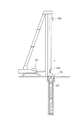
次に、図1に示すステップS22「外周掘削」工程にて、ケーシング20を用いて既設杭12の外周部に沿って掘削を行う。外周掘削工程では、図4に示すように、先端に掘削用のビットを取り付けた円筒形状のケーシング20をクレーン18を用いて吊るし、ケーシング20の内部に既設杭12が入るように位置決めしてから、ケーシング20を回転させながら下降させる。これにより、既設杭12の外周部に沿って掘削してゆくことができる。外周掘削工程では、掘削抵抗を減少させるために、ジェット水を噴出させながらケーシング20を下降させてもよい。なお、図4中、符号19Aはクレーンの主ワイヤフックであり、符号19Bはクレーンの副ワイヤフックである。
Next, excavation is performed along the outer periphery of the existing
次に、図1に示すステップS24「外周掘削完了?」にて、既存のケーシング20を用いて掘削することが可能な深さまで掘削したものの、未だ掘削深さが既設杭12の底部まで到達していないと判断した場合には、ステップS26「ケーシングジョイント」工程に分岐し、一端地上に出ている接続部でケーシング20を分離し、新たな延長ケーシングを間に継ぎ足して再びステップS22の外周掘削工程を実行する。
Next, in step S24 “External excavation completed?” Shown in FIG. 1, the excavation depth has reached the bottom of the existing
図1に示すステップS24「外周掘削完了?」にて、掘削深さが既設杭12の底部まで到達したと判断した場合には、次のステップS28「既設杭縁切り確認」工程に進み、既設杭12が地面から抜き取ることが可能な状態にあるか否かの確認作業を行う。
If it is determined in step S24 “Period excavation completed?” Shown in FIG. 1 that the excavation depth has reached the bottom of the existing
次に、図1に示すステップS30「ケーシング引抜き」工程にて、図5に示すようにクレーン18を用いて掘削に用いたケーシング20を地中から引き抜く作業を行う。
Next, in step S30 “casing extraction” step shown in FIG. 1, the
次に、図1に示すステップS32「玉掛けワイヤーセット」工程にて、図6に示すように、引き上げたケーシング20の先端に杭抜き用のワイヤー22の輪をからげる。そのワイヤーの他端は、クレーンの副ワイヤフック19Bに掛ける。そして、再びケーシング20を地中に戻して玉掛けワイヤー22の輪を既設杭12の上部(上端から概ね3m程度)に掛ける。この作業は、副ワイヤフック19Bを緩めてケーシング20の先端にからげたワイヤー22をその先端から外し、副ワイヤフック19Bを再度張ってワイヤー22を既設杭12に掛ける。玉掛けワイヤー22の輪が既設杭12に掛かったら、ワイヤー22が外れたケーシング20をクレーンにより引き上げ、図7に示すように再びケーシング20を引き抜く。
Next, in the step S32 “sling wire setting” step shown in FIG. 1, a ring of the
次に、ケーシング20を撤去して、図8に示すように、掘削機14(既設杭12が短い場合)又はクレーン18(既設杭12が長い場合)等を既設杭12近くの地上に配置して、副ワイヤフック19Bに掛かっていた玉掛けワイヤー22の上端を、図8に示すように、掘削機14又はクレーン18の主ワイヤフック19Bに掛け換えて既設杭12を引き抜く準備を行う。なお、このとき、ケーシング20作業時のクレーン18をそのまま用いてもよいし、別のクレーンを用いてもよい。
Next, the
そして、図1に示すステップS34「埋戻剤供給管配設」工程に進み、既設杭12の外周部に沿って掘削した穴に、埋戻剤供給管24を挿入してゆく。このとき、埋戻剤供給管24下端の埋戻剤30の吐出口が、杭抜き穴の底部付近に到達するように、例えば副ワイヤフック19Bを用いて配設する。杭抜き穴の深さが数メートル以上である場合には、後述の図14に示すように、複数の埋戻剤供給管24を接続して、埋戻剤30の吐出口を杭抜き穴の底部付近まで到達させておく必要がある。埋戻剤供給管24の全体構造、接続構造及び接続方法については、別途後段にて説明する。
And it progresses to step S34 "backfilling agent supply pipe arrangement | positioning" process shown in FIG. 1, and the backfilling agent supply pipe |
ケーシング20を用いて外周掘削を行った場合には、既設杭12の周囲に円筒形の掘削穴が開口している。一般に、ケーシング20を用いて外周掘削を行った後に開口する円筒形の掘削穴の内径と外径の差は、100〜200mm程である。したがって、この円筒形の掘削穴に挿入する埋戻剤供給管24は、外径80mm程度、又はそれ以下の太さの管を用いることが好ましい。なお、これらの寸法は任意の設計事項である。
When the outer periphery excavation is performed using the
既設杭12近くの地上部分には、埋戻剤30を供給するための埋戻剤供給プラント26を設置して、図8に示すように、埋戻剤供給管24の上部に埋戻剤供給用エルボ25Bと埋戻剤供給用ホース25Aを接続する。埋戻剤30は、例えば当該地盤性状や土地質に応じて調製したセメントミルクやモルタルに、圧送用の流動化剤を混合したものを用いる。
A backfilling
埋戻剤供給管24を複数接続し、配設が終了したら、図1に示すステップS36「埋戻剤吐出」工程に進み、図8に示すように埋戻剤供給プラント26から埋戻剤30を圧送し、埋戻剤供給管24の吐出口から埋戻剤30を吐出させて、埋戻剤30を掘削穴の底部に溜めておく。
When a plurality of backfilling
なお、掘削穴の内部に地下水や砂利、掘削に使用したジェット水等の不純物32が予め溜まっている場合には、埋戻剤供給管24の吐出口から埋戻剤30を吐出させることによって、これらの不純物32が浮き上がってくる。したがって、地中における埋戻剤30の充填むらを減少させることが可能となり、地盤変状を改善することができる。
In the case where
次に、図1に示すステップS38「既設杭引上埋戻」工程にて、図9に示すようにクレーン18を用いて玉掛けワイヤー22を引き上げて、既設杭12を上昇させる。玉掛けワイヤー22の引上げに伴って地上に現れた既設杭12の外周部分には、ケーシング20により掘削されなかった土や泥が付着しているので、既設杭12の引上げ時にはこれらの土や泥を水圧で落としながら行う。
Next, in step S38 “existing pile pulling back-filling” process shown in FIG. 1, the
既設杭12を引き上げる際には、この既設杭12の引抜きと同時に埋戻剤供給管24先端の吐出口から埋戻剤30を吐出させておく。このように、埋戻剤供給管24を介して埋戻剤30を供給しながら既設杭12を引き上げることによって、引き抜きつつある既設杭12の下方に空隙を作ることなく、より確実に杭抜き穴に埋戻剤30を充填することができる。これにより、地中における埋戻剤30の充填むらを減少させることが可能となり、地盤変状を改善することができる。また、既設杭12の引抜き作業と埋戻剤30の充填作業とを同時に行うので、杭抜き埋戻し作業の工期を短縮することができる。
When pulling up the existing
なお、既設杭12の長さが数メートルを超える長さを有する場合には、図9に示すように引き上げた既設杭12の上部を適宜切除し、且つ玉掛けワイヤー22を掛け換えながら引抜き作業を継続する。既設杭12を全て引抜いたら、配設した埋戻剤供給管24を引き上げる。複数の埋戻剤供給管24を接続している場合には、通常、後述する図15〜図17に示す係合保持管90を外し、個々の戻剤供給管24を外しながら引き上げる。
In addition, when the length of the existing
次に、図10を用いて、既設杭引上埋戻工程の他の実施形態について説明する。図9では、既設杭12のみを引き上げる実施形態について説明したが、図10に示す実施形態では、既設杭引上埋戻工程において、埋戻剤30の供給及び既設杭12の引き上げと併せて埋戻剤供給管24を引き上げている。このように、埋戻剤30の供給及び既設杭12の引き上げと併せて埋戻剤供給管24を引き上げることによって、固化が速い埋戻剤30を用いる場合や、既設杭12が長いために引抜き作業に時間がかかる場合においても、これらの条件に関わらず埋戻剤30の充填処理をより確実に行って、埋め戻した後の地盤変状を減少させることができる。
Next, another embodiment of the existing pile pulling backfilling step will be described with reference to FIG. In FIG. 9, the embodiment in which only the existing
なお、複数の埋戻剤供給管24を接続して使用している場合において、埋戻剤供給管24を引き上げてゆく場合には、引き上げにより地上に出た埋戻剤供給管24を順次接続部にて分離して外し、長さを詰めながら行う。長さを詰めた埋戻剤供給管24の上部には、埋戻剤供給用エルボ25Bと埋戻剤供給用ホース25Aを再接続し、埋戻剤30を供給する。
When a plurality of backfilling
既設杭12の引上げと埋戻剤供給管24の引上げが完了したら、クレーン18及び埋戻剤供給プラント26を撤去する。そして、既設杭引上埋戻工程を終了する。この工程終了後の態様を図11に示す。
When the lifting of the existing
次に、図1に示すステップS42「杭抜き穴埋戻し」工程では、図12に示すようにバックホー等の掘削機14を用いて、杭抜き穴に土砂を投入して埋め戻す作業を行う。そして、杭抜埋戻工法を終了する。以上のようにして、杭抜き作業と埋戻し作業とを並行して行うことができる。この埋め戻し作業において、不純物32は予め除去して埋め戻してもよいし、不純物32を残した状態で埋め戻してもよい。
Next, in step S42 “pile-out hole backfilling” step shown in FIG. 1, as shown in FIG. 12, the
次に、図1に示すステップS44「スタンドパイプ除去」工程にて、杭抜き穴上部に配置しておいたスタンドパイプ16を引き上げて、杭抜き穴からスタンドパイプ16を除去する。杭抜き穴上部からスタンドパイプ16を除去した後には、必要に応じて、除去後の隙間等を土砂で埋め戻してもよい。
Next, in step S44 “stand pipe removal” step shown in FIG. 1, the
なお、図1に示すステップS42の工程とステップS44の工程とは、逆にしても構わない。すなわち、ステップS38の既設杭引上埋戻工程の後に、「スタンドパイプ除去」工程、杭抜き穴埋戻し工程の順であってもよい。 Note that the step S42 shown in FIG. 1 and the step S44 may be reversed. That is, after the existing pile pulling backfilling step in step S38, the order of the “stand pipe removal” step and the pile punching hole backfilling step may be performed.
本発明に係る杭抜埋戻工法は、PC杭、PHC杭、BT杭、鋼管杭、松杭、摩擦杭などの既成の杭や、ED杭、リバース杭、ペデスタル杭等の場所打ちした既設杭等の引抜きに用いることができる。また、本発明に係る杭抜埋戻工法が対応可能な既設杭の太さはケーシング20の内径に依存する。現在では直径2m程度の杭まで対応することが可能である。他方、既設杭の長さ(深さ)は、現在では80m程度まで対応可能である。また、本発明は、斜めに埋まっている既設杭の杭抜埋戻工法にも適用することができる。
The pile unfilling method according to the present invention includes existing piles such as PC piles, PHC piles, BT piles, steel pipe piles, pine piles and friction piles, and existing piles such as ED piles, reverse piles and pedestal piles. It can be used for drawing out. In addition, the thickness of the existing pile that can be handled by the pile unfilling method according to the present invention depends on the inner diameter of the
次に、図13を用いて複数の既設杭の埋戻跡42と、次に埋設する新規杭44との位置関係について説明する。図13に示すように、既設杭の埋戻跡42と次に埋設する新規杭44の位置とが重なる場合には、既設杭の埋戻跡42とその他の地盤の土地質が一致していないと、新規杭44を埋設する際に鉛直に掘削や埋設ができなくなるという不具合が発生する。特に、新規杭44の深さが深い場合には、重大な問題となる。本発明に係る杭抜埋戻工法を用いることによって、杭抜き穴に埋戻剤をより確実に充填することが可能となり、既設杭を引き抜いて埋め戻した後の埋戻跡42における地盤変状を減少させることができる。
Next, the positional relationship between the reclaimed traces 42 of a plurality of existing piles and the
(埋戻剤供給管の接続構造)
次に、埋戻剤供給管の全体構造及びその接続構造について、図14〜図18を用いて説明する。
(Connection structure of backfilling agent supply pipe)
Next, the overall structure of the backfilling agent supply pipe and the connection structure thereof will be described with reference to FIGS.
図14は、埋戻剤供給管24の全体構造図である。本発明では、杭抜き穴の深さが数メートル以上である場合に、複数の埋戻剤供給管24を接続して、埋戻剤の吐出口を杭抜き穴の底部付近まで到達させる。その接続構造及び接続方法は以下のとおりである。
FIG. 14 is an overall structural view of the backfilling
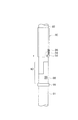
図15は、長尺の第1埋戻剤供給管81及び第2埋戻剤供給管82における接続部80の構造及び係合保持管90の形状を説明する図である。図16は、第1埋戻剤供給管81と第2埋戻剤供給管82とを接続部80にて接続して接続部80の外周部に係合保持管90を被せる前の状態を示す図である。図17は、第1埋戻剤供給管81と第2埋戻剤供給管82とを接続して接続部80の外周部に本発明に係る係合保持管90を被せ、第1埋戻剤供給管81の外周部の一部に突出させたロック凸部88を係合保持管90の導入溝92へ通して円周溝94に到達させた状態を示す図である。図18は、図17に示した状態から係合保持管90を左方向に回転させることにより、ロック凸部88を係合保持管90の円周溝94に沿って通してゆき、回動防止溝96に到達させて係合保持管90を下方に下げた状態を示す図である。
FIG. 15 is a view for explaining the structure of the connecting
図15に示すように、長尺の第1埋戻剤供給管81の端部には、半円筒形状に切除して形成した半円筒部83と、当該半円筒部83の先端内筒面に係合用の内接円筒管85を取着した内接円筒管突出部86とを有する接続部80が形成されている。また、同様に、長尺の第2埋戻剤供給管82の端部には、半円筒形状に切除して形成した半円筒部83と、当該半円筒部83の先端内筒面に係合用の内接円筒管85を取着した内接円筒管突出部86とを有する接続部80が形成されている。
As shown in FIG. 15, the end portion of the long first backfilling
第1埋戻剤供給管81の接続部80における外周部の一部には、ロック凸部88を突出させてある。ロック凸部88は、例えば一辺が2〜4cm程度の四角形の板材、又は直径が2〜4cm程度の円形の板材を、溶接、ロウ付け、又は螺合等により第1埋戻剤供給管81の外周部に取り付けて形成することができる。
A
また、図15に示すように、係合保持管90の管淵部には、当該係合保持管90の軸と平行に開設した導入溝92を開設してある。導入溝92上部の側部は、当該係合保持管90の円周方向に開設した溝を有する円周溝94に繋がる導入部93となっている。円周溝94の他端は、当該係合保持管90における管淵部から離間する軸方向(図15に示す実施形態では、図15の紙面の上方)に向けて開設した回動防止溝96を開設してある。
Further, as shown in FIG. 15, an
係合保持管90に形成した導入溝92は、当該係合保持管90を第1埋戻剤供給管81及び第2埋戻剤供給管82の外周に沿って下降させていった際に、ロック凸部88を円周溝94に案内するために通す溝である。
The
円周溝94は、ロック凸部88を回動防止溝96に案内するための溝であるとともに、係合保持管90が外力によって上下方向に摺動した場合であっても、回動防止溝96に案内したロック凸部88が導入溝92を通って係合保持管90の外部に出てしまわないようにするための緩衝部分である。
The
回動防止溝96は、係合保持管90が外力によって上下方向に摺動した場合であっても、ロック凸部88が直ちに円周溝94を通って係合保持管90の外部に出てしまわないようにするための溝である。
Even when the
第1埋戻剤供給管81と第2埋戻剤供給管82とを接続する場合には、先ず第2埋戻剤供給管82に係合保持管90を通しておく。次に、第1埋戻剤供給管81及び第2埋戻剤供給管82の軸を平行にずらして、それぞれの埋戻剤供給管の接続部80を向かい合わせた状態から、第1埋戻剤供給管81の接続部80に形成した半円筒部83の内部に第2埋戻剤供給管82の接続部80の内接円筒管突出部86を嵌入すると同時に、第2埋戻剤供給管82の接続部80に形成した半円筒部83の内部に第1埋戻剤供給管81の接続部80の内接円筒管突出部を嵌入して第1埋戻剤供給管81及び第2埋戻剤供給管82の軸を一致させる。この状態が図16に示す状態である。
When connecting the first backfilling
その後に、図17に示すように、第1埋戻剤供給管81及び第2埋戻剤供給管82の接続部80の外周部に係合保持管90を移動させて被せるとともに、第1埋戻剤供給管81の外周部の一部に突出させたロック凸部88を係合保持管90の導入溝92へ通して円周溝94に到達させる。
After that, as shown in FIG. 17, the
次に図18に示すように、図17に示した状態から係合保持管90を左方向に回転させて、ロック凸部88を係合保持管90の円周溝94に沿って通して、回動防止溝96に到達させる。一般的には、第1埋戻剤供給管81は掘削穴に挿入してあるので、第1埋戻剤供給管81及び第2埋戻剤供給管82の軸は鉛直に配置されている。したがって、ロック凸部88が回動防止溝96に到達すると、係合保持管90の自重により係合保持管90が下方に下がるので、ロック凸部88は回動防止溝96の上部にて停止した状態となる。
Next, as shown in FIG. 18, the
係合保持管90が、図18に示すように回動防止溝96の上部に停止した状態になると、例えば第1埋戻剤供給管81及び第2埋戻剤供給管82を掘削穴に挿入してゆく場合に係合保持管90が掘削穴の側壁と接触して係合保持管90が上方にずれた場合であっても、ロック凸部88が回動防止溝96の下端に当接するので、それ以上係合保持管90が上方に摺動することを防止することができる。したがって、より確実に係合保持管90を接続部80に保持しておくことができるので、第1埋戻剤供給管81と第2埋戻剤供給管82との係合状態を拘束しておくことができる。
When the
次に、図19〜図23を用いて、係合保持管における円周溝及び回動防止溝の他の実施形態について説明する。 Next, another embodiment of the circumferential groove and the rotation prevention groove in the engagement holding pipe will be described with reference to FIGS.
図19は、長さが異なる二種類の円周溝94及び円周溝94aを、一つの係合保持管90aに形成した実施形態を示す図である。なお、図15にて説明した部位と同一の機能を有する部位については、同一の符号を付してその説明を省略する。
FIG. 19 is a diagram showing an embodiment in which two types of
図19に示す係合保持管90aの下部に形成した円周溝94における平行部の長さはL1である。他方、図19に示す係合保持管90aの上部に形成した円周溝94aにおける平行部の長さは、L1よりも長いL2に設定してあり、現場の状況に応じて係合保持管90aの上下方向を入れ換えて使用することを可能にしている。
The length of the parallel part in the
例えば円周溝94aのように、平行部の長さが長い円周溝94aの方が、回動防止溝96に案内したロック凸部88が外れにくい。したがって、埋戻剤供給管を挿入する掘削穴が深い場合、又は掘削穴が狭いために、係合保持管90aが頻繁に掘削穴の側壁に接触することが予想される場合等においては、円周溝94aを形成した溝が下側になるように係合保持管90aを配置して、ロック凸部88を円周溝94aに通して回動防止溝96に入れて使用すると良い。
For example, like the
他方、円周溝94のように、平行部の長さが短い円周溝の方が、ロック凸部88を回動防止溝96まで案内する作業が容易である。したがって、埋戻剤供給管を挿入する掘削穴が浅い場合、又は掘削穴が広いために係合保持管90aが掘削穴の側壁にそれほど接触しないと予想される場合等においては、円周溝94を形成した溝が下側(図19に示す状態)になるように係合保持管90aを配置して、ロック凸部88を円周溝94に通して回動防止溝96に入れて使用すると良い。
On the other hand, a circumferential groove having a short parallel portion, such as the
次に、回動防止溝96の他の実施形態について、図20を用いて説明する。なお、図15にて説明した部位と同一の機能を有する部位については、同一の符号を付してその説明を省略する。
Next, another embodiment of the
図20は、図19に示した回動防止溝96に加えて、円周溝94の他端において、係合保持管90bの管淵部に向かう回動防止溝97を開設した実施形態を示す図である。係合保持管90bの管淵部に向かう回動防止溝97を開設しておくことによって、例えば第1埋戻剤供給管81及び第2埋戻剤供給管82を掘削穴に挿入してゆく場合に係合保持管90bが掘削穴の側壁と接触して係合保持管90bが上方にずれた場合であっても、ロック凸部88aが回動防止溝97に入り込むことになる。これにより、それ以上係合保持管90bが上方に摺動することを防止すると共に、係合保持管90bの回動動作を制限することができるので、ロック凸部88aが円周溝94に入り込んでしまうことを防止することができる。したがって、より確実に係合保持管90bを接続部80に保持しておくことができる。
20 shows an embodiment in which, in addition to the
なお、図20に示す実施形態では、ロック凸部88aの平面形状を円形に形成してある。ロック凸部の平面形状は、図15等に示すような四角形の平面形状のものを用いることもできるし、図20に示すような円形の平面形状のものを用いることもできる。
In the embodiment shown in FIG. 20, the planar shape of the
次に、円周溝94と、回動防止溝96及び回動防止溝97との間の接続形状の他の実施形態について、図21を用いて説明する。図21に示す係合保持管90cは、円周溝94から回動防止溝96及び回動防止溝97に繋がる部分に、傾斜面98を形成した実施形態を説明する図である。なお、図15、図19、及び図20にて説明した部位と同一の機能を有する部位については、同一の符号を付してその説明を省略する。
Next, another embodiment of the connection shape between the
図21に示すように、円周溝94から回動防止溝96及び回動防止溝97に繋がる部分に傾斜面98を形成することによって、係合保持管90cが上下方向及び回動方向にずれる動きを伴った場合であっても、ロック凸部88が回動防止溝96又は回動防止溝97に戻されるように係合保持管90cが回動するので、ロック凸部88が円周溝94に入り込んでしまう不具合を減少させることができる。したがって、より確実に係合保持管90cを接続部80に保持しておくことができる。
As shown in FIG. 21, by forming an
次に、円周溝が係合保持管の管淵部に開口している係合保持管の実施形態について、図22を用いて説明する。図22に示す係合保持管90dは、図19〜図21に示したような導入溝92を有しておらず、円周溝94が係合保持管90dの管淵部に開口している係合保持管90dの実施形態を示す図である。なお、図15及び図19〜図21にて説明した部位と同一の機能を有する部位については、同一の符号を付してその説明を省略する。
Next, an embodiment of the engagement holding tube in which the circumferential groove is opened in the tube flange portion of the engagement holding tube will be described with reference to FIG. The
図22に示すように、係合保持管90dにおける管淵部を半円筒形状に切除し、円周溝92の導入部93を係合保持管90dの切除した淵部に形成するように構成しても、本発明の目的を達成することができる。
As shown in FIG. 22, the tubular hook portion of the
次に、円周溝が係合保持管の管淵部に開口している係合保持管の他の実施形態について、図23を用いて説明する。図23に示す係合保持管90eも、図19〜図21に示したような導入溝92を有しておらず、斜めに開設した円周溝94が係合保持管90dの管淵部に開口している。なお、図15及び図19〜図22にて説明した部位と同一の機能を有する部位については、同一の符号を付してその説明を省略する。
Next, another embodiment of the engagement holding tube in which the circumferential groove is opened in the tube flange portion of the engagement holding tube will be described with reference to FIG. The
図23に示すように、管淵部から斜めに開設した円周溝92の導入部93を係合保持管90dの管淵部に形成しても、本発明の目的を達成することができる。
As shown in FIG. 23, the object of the present invention can be achieved even if the
12 既設杭
14 掘削機
16 スタンドパイプ
18 クレーン(杭抜き機)
19A 主ワイヤフック
19B 副ワイヤフック
20 ケーシング
22 ワイヤー
24 埋戻剤供給管
25A 埋戻剤供給用ホース
25B 埋戻剤供給用エルボ
26 埋戻剤供給プラント
30 埋戻剤
32 ジェット水等の不純物
42 埋戻跡
44 新規杭
80、980 接続部
81、981 第1埋戻剤供給管
82、982 第2埋戻剤供給管
83、983 半円筒部
85、985 内接円筒管
86、986 内接円筒管突出部
88、88a ロック凸部
90、90a、90b、90c、90d、90e、990 係合保持管
92 導入溝
93 導入部
94、94a 円周溝
96 回動防止溝
97 回動防止溝
98 傾斜面
992 針金
994 ガムテープ
12 Existing
19A
Claims (2)
前記第1及び第2の埋戻剤供給管の軸を平行にずらして前記それぞれの接続部を向かい合わせた状態から、前記第1の埋戻剤供給管接続部に形成した半円筒部の内部に前記第2の埋戻剤供給管接続部の内接円筒管突出部を嵌入すると同時に、前記第2の埋戻剤供給管接続部に形成した半円筒部の内部に前記第1の埋戻剤供給管接続部の内接円筒管突出部を嵌入して前記第1及び第2の埋戻剤供給管の軸を一致させた後に、前記第1及び第2の埋戻剤供給管接続部の外周部に被せることによって前記第1及び第2の埋戻剤供給管の係合状態を拘束する係合保持管と、を備える埋戻剤供給管の接続構造において、
前記第1の埋戻剤供給管接続部における外周部の一部に突出させたロック凸部と、
前記ロック凸部を通過させることが可能な、前記係合保持管に開設した溝であって、一端に前記ロック凸部の入出を可能にする導入部を有すると共に少なくとも当該係合保持管の円周方向に開設した溝を有する円周溝と、当該円周溝から当該係合保持管の軸方向に向けて開設した回動防止溝と、
を備えることを特徴とする埋戻剤供給管の接続構造。 A semi-cylindrical portion formed by cutting an end portion of the long tube into a semi-cylindrical shape, and an inscribed cylindrical tube protruding portion in which an inscribed cylindrical tube for engagement is attached to the inner cylindrical surface of the tip of the semi-cylindrical portion First and second backfilling agent supply pipes each formed with a connecting portion;
The inside of the semi-cylindrical part formed in the first backfilling agent supply pipe connecting part from the state where the respective connecting parts face each other with the axes of the first and second backfilling agent supply pipes being shifted in parallel. The projecting portion of the inscribed cylindrical tube of the second backfilling agent supply pipe connecting portion is inserted into the semi-cylindrical portion formed in the second backfilling agent supply tube connecting portion. The first and second backfilling agent supply pipe connecting portions are inserted after fitting the inscribed cylindrical tube projecting portion of the agent supply pipe connecting portion to align the axes of the first and second backfilling agent supply pipes. In the connecting structure of the backfilling agent supply pipe, comprising an engagement holding pipe that restrains the engagement state of the first and second backfilling agent supply pipes by covering the outer periphery of the backfilling agent supply pipe,
A lock protrusion protruding from a part of the outer peripheral portion of the first backfilling agent supply pipe connecting portion;
A groove formed in the engagement holding tube through which the lock projection can be passed, and has an introduction portion that allows the lock projection to enter and exit at one end and at least a circle of the engagement holding tube. A circumferential groove having a groove opened in the circumferential direction, and a rotation preventing groove opened from the circumferential groove toward the axial direction of the engagement holding tube,
A connection structure for a backfilling agent supply pipe.
前記係合保持管の回動防止溝は、前記円周溝から当該係合保持管の軸と平行な双方向に向けて開設したことを特徴とする埋戻剤供給管の接続構造。
In the connection structure of the backfilling agent supply pipe according to claim 1,
The connecting structure of the backfilling agent supply pipe, wherein the rotation prevention groove of the engagement holding pipe is opened from the circumferential groove in both directions parallel to the axis of the engagement holding pipe.
Priority Applications (1)
| Application Number | Priority Date | Filing Date | Title |
|---|---|---|---|
| JP2015025003A JP5996688B2 (en) | 2015-02-12 | 2015-02-12 | Connection structure of backfilling agent supply pipe |
Applications Claiming Priority (1)
| Application Number | Priority Date | Filing Date | Title |
|---|---|---|---|
| JP2015025003A JP5996688B2 (en) | 2015-02-12 | 2015-02-12 | Connection structure of backfilling agent supply pipe |
Related Parent Applications (1)
| Application Number | Title | Priority Date | Filing Date |
|---|---|---|---|
| JP2010260870A Division JP5890606B2 (en) | 2010-11-24 | 2010-11-24 | Pile unfilling method |
Publications (2)
| Publication Number | Publication Date |
|---|---|
| JP2015110902A true JP2015110902A (en) | 2015-06-18 |
| JP5996688B2 JP5996688B2 (en) | 2016-09-21 |
Family
ID=53525899
Family Applications (1)
| Application Number | Title | Priority Date | Filing Date |
|---|---|---|---|
| JP2015025003A Active JP5996688B2 (en) | 2015-02-12 | 2015-02-12 | Connection structure of backfilling agent supply pipe |
Country Status (1)
| Country | Link |
|---|---|
| JP (1) | JP5996688B2 (en) |
Cited By (5)
| Publication number | Priority date | Publication date | Assignee | Title |
|---|---|---|---|---|
| JP2017066721A (en) * | 2015-09-30 | 2017-04-06 | 株式会社大林組 | Removal method of existing pile |
| JP2017166160A (en) * | 2016-03-15 | 2017-09-21 | 株式会社江機 | Connection structure between bucket and connection casing, and excavated hole backfill method |
| JP6284255B1 (en) * | 2017-11-15 | 2018-02-28 | 株式会社徳永組 | Pile cap and pile drawing method |
| JP6284253B1 (en) * | 2017-06-15 | 2018-02-28 | 株式会社徳永組 | Pile catcher and pile removal method using pile catcher |
| JP2019094742A (en) * | 2017-11-28 | 2019-06-20 | 鹿島建設株式会社 | Pile removal method |
Citations (7)
| Publication number | Priority date | Publication date | Assignee | Title |
|---|---|---|---|---|
| US2863685A (en) * | 1956-01-20 | 1958-12-09 | Chance Vought Aircraft Inc | High-strength light-weight quick-disconnect coupling for a linkage system |
| US3220757A (en) * | 1962-03-22 | 1965-11-30 | David M Potter | Quick-disconnect coupling |
| JPH0294503U (en) * | 1989-01-17 | 1990-07-27 | ||
| JPH0684094U (en) * | 1993-05-14 | 1994-12-02 | マックス株式会社 | Quick fitting |
| US5407292A (en) * | 1993-06-08 | 1995-04-18 | Halliburton Company | Connector assembly for connecting two cylindrical members |
| JPH10331158A (en) * | 1997-06-02 | 1998-12-15 | Kinuta Yoko:Kk | Device for rotating and press-inserting steel pipe pile |
| JPH11190021A (en) * | 1997-10-24 | 1999-07-13 | Housing Tamura:Kk | Joint construction for pile |
-
2015
- 2015-02-12 JP JP2015025003A patent/JP5996688B2/en active Active
Patent Citations (7)
| Publication number | Priority date | Publication date | Assignee | Title |
|---|---|---|---|---|
| US2863685A (en) * | 1956-01-20 | 1958-12-09 | Chance Vought Aircraft Inc | High-strength light-weight quick-disconnect coupling for a linkage system |
| US3220757A (en) * | 1962-03-22 | 1965-11-30 | David M Potter | Quick-disconnect coupling |
| JPH0294503U (en) * | 1989-01-17 | 1990-07-27 | ||
| JPH0684094U (en) * | 1993-05-14 | 1994-12-02 | マックス株式会社 | Quick fitting |
| US5407292A (en) * | 1993-06-08 | 1995-04-18 | Halliburton Company | Connector assembly for connecting two cylindrical members |
| JPH10331158A (en) * | 1997-06-02 | 1998-12-15 | Kinuta Yoko:Kk | Device for rotating and press-inserting steel pipe pile |
| JPH11190021A (en) * | 1997-10-24 | 1999-07-13 | Housing Tamura:Kk | Joint construction for pile |
Cited By (7)
| Publication number | Priority date | Publication date | Assignee | Title |
|---|---|---|---|---|
| JP2017066721A (en) * | 2015-09-30 | 2017-04-06 | 株式会社大林組 | Removal method of existing pile |
| JP2017166160A (en) * | 2016-03-15 | 2017-09-21 | 株式会社江機 | Connection structure between bucket and connection casing, and excavated hole backfill method |
| JP6284253B1 (en) * | 2017-06-15 | 2018-02-28 | 株式会社徳永組 | Pile catcher and pile removal method using pile catcher |
| JP2019002195A (en) * | 2017-06-15 | 2019-01-10 | 株式会社徳永組 | Pile catcher and pile extraction method using the same |
| JP6284255B1 (en) * | 2017-11-15 | 2018-02-28 | 株式会社徳永組 | Pile cap and pile drawing method |
| JP2019002265A (en) * | 2017-11-15 | 2019-01-10 | 株式会社徳永組 | Pile cap, and method for pulling out pile |
| JP2019094742A (en) * | 2017-11-28 | 2019-06-20 | 鹿島建設株式会社 | Pile removal method |
Also Published As
| Publication number | Publication date |
|---|---|
| JP5996688B2 (en) | 2016-09-21 |
Similar Documents
| Publication | Publication Date | Title |
|---|---|---|
| JP5890606B2 (en) | Pile unfilling method | |
| JP5996688B2 (en) | Connection structure of backfilling agent supply pipe | |
| JP5199166B2 (en) | Foundation pile structure by site construction and construction method of foundation pile | |
| JP6343445B2 (en) | Construction method of earth retaining wall | |
| JP2008175012A (en) | Cast-in-place pile construction method and construction apparatus | |
| JP5502538B2 (en) | Pile construction method and pile construction device | |
| EP1857597A2 (en) | Method and pile-driving device for inserting foundation piles into the ground | |
| JP5078511B2 (en) | Embedded pile method using earth drill machine | |
| JP2013002039A (en) | Air hammer device for drilling | |
| JP2008014000A (en) | Construction method of cast-in-place concrete pile | |
| KR101241382B1 (en) | Micro pile capable of withdrawing upper cassing and method for constructing foundation using the same | |
| JP2007332559A (en) | Removal method for existing underground pile | |
| JP5698316B2 (en) | Construction method of foundation pile | |
| CN110273413A (en) | A kind of efficient construction method of prefabricated pile | |
| ITTO20110913A1 (en) | PROCEDURE FOR THE CONSTRUCTION OF LARGE DIAMETER POLES AND EXCAVATION TOOL | |
| JP6260931B2 (en) | Steel pipe pile and its embedding method | |
| JP4341029B2 (en) | Pile foundation method | |
| KR20190035350A (en) | Pile removal apparatus | |
| JP2012140787A (en) | Construction method of pile body and casing pipe used for the same, and foundation structure constructed thereby | |
| JP2004131923A (en) | Extracting method for existing underground structure | |
| JP6636362B2 (en) | Connection structure between bucket and connection casing and backfill method of excavation hole | |
| JP4400700B2 (en) | Cutting and drawing method and equipment for existing piles | |
| JP6735138B2 (en) | Construction method of retaining wall structure and retaining wall structure | |
| JP2020169455A (en) | Construction method of soil cement continuous wall | |
| JP2019094742A (en) | Pile removal method |
Legal Events
| Date | Code | Title | Description |
|---|---|---|---|
| A977 | Report on retrieval |
Free format text: JAPANESE INTERMEDIATE CODE: A971007 Effective date: 20151120 |
|
| A131 | Notification of reasons for refusal |
Free format text: JAPANESE INTERMEDIATE CODE: A131 Effective date: 20151201 |
|
| A521 | Request for written amendment filed |
Free format text: JAPANESE INTERMEDIATE CODE: A523 Effective date: 20160118 |
|
| A131 | Notification of reasons for refusal |
Free format text: JAPANESE INTERMEDIATE CODE: A131 Effective date: 20160621 |
|
| A521 | Request for written amendment filed |
Free format text: JAPANESE INTERMEDIATE CODE: A523 Effective date: 20160627 |
|
| TRDD | Decision of grant or rejection written | ||
| A01 | Written decision to grant a patent or to grant a registration (utility model) |
Free format text: JAPANESE INTERMEDIATE CODE: A01 Effective date: 20160802 |
|
| A61 | First payment of annual fees (during grant procedure) |
Free format text: JAPANESE INTERMEDIATE CODE: A61 Effective date: 20160824 |
|
| R150 | Certificate of patent or registration of utility model |
Ref document number: 5996688 Country of ref document: JP Free format text: JAPANESE INTERMEDIATE CODE: R150 |
|
| R250 | Receipt of annual fees |
Free format text: JAPANESE INTERMEDIATE CODE: R250 |
|
| R250 | Receipt of annual fees |
Free format text: JAPANESE INTERMEDIATE CODE: R250 |
|
| R250 | Receipt of annual fees |
Free format text: JAPANESE INTERMEDIATE CODE: R250 |
|
| R250 | Receipt of annual fees |
Free format text: JAPANESE INTERMEDIATE CODE: R250 |
|
| R250 | Receipt of annual fees |
Free format text: JAPANESE INTERMEDIATE CODE: R250 |