JP2015106975A - Motor control device - Google Patents
Motor control device Download PDFInfo
- Publication number
- JP2015106975A JP2015106975A JP2013247521A JP2013247521A JP2015106975A JP 2015106975 A JP2015106975 A JP 2015106975A JP 2013247521 A JP2013247521 A JP 2013247521A JP 2013247521 A JP2013247521 A JP 2013247521A JP 2015106975 A JP2015106975 A JP 2015106975A
- Authority
- JP
- Japan
- Prior art keywords
- command
- motor
- drive
- control means
- estimated
- Prior art date
- Legal status (The legal status is an assumption and is not a legal conclusion. Google has not performed a legal analysis and makes no representation as to the accuracy of the status listed.)
- Pending
Links
Images


Landscapes
- Hybrid Electric Vehicles (AREA)
- Electric Propulsion And Braking For Vehicles (AREA)
- Control Of Electric Motors In General (AREA)
Abstract
Description
この発明は、ハイブリッド自動車や電気自動車等の車両に搭載されたモータ制御装置に関する。 The present invention relates to a motor control device mounted on a vehicle such as a hybrid vehicle or an electric vehicle.
近年は、ハイブリッド自動車、電気自動車、燃料電池車等の環境に配慮した車両が注目されている。これらの車両は、駆動源である走行用のモータをモータ制御装置によって駆動制御している。ハイブリッド自動車や電気自動車に搭載されるモータ制御装置においては、モータの駆動制御が破綻することなどにより、モータのトルク異常が生じると、モータの構成部品の摩耗や損傷の不具合が発生する可能性がある。 In recent years, environmentally friendly vehicles such as hybrid vehicles, electric vehicles, and fuel cell vehicles have attracted attention. In these vehicles, a driving motor as a driving source is driven and controlled by a motor control device. In a motor control device mounted on a hybrid vehicle or an electric vehicle, if a motor torque abnormality occurs due to a failure of motor drive control, there is a possibility that a malfunction or damage of motor components may occur. is there.
このようなモータのトルク異常を抑制するために、モータの駆動トルクが通常よりも大きい状態を検知すると、モータヘの電力供給を遮断し車両を停止させる制御がある。特開2006−230051号公報には、内燃機関及び発電用及び走行用のモータを備えたハイブリッド自動車において、モータが想定外の駆動トルクを発生しているときには、バッテリからモータヘの電力の供給を遮断することで、内燃機関及びモータの過回転を防止した装置が開示されている。 In order to suppress such torque abnormality of the motor, there is a control for stopping the vehicle by cutting off the power supply to the motor when detecting a state where the driving torque of the motor is larger than usual. Japanese Patent Laid-Open No. 2006-230051 discloses that in a hybrid vehicle equipped with an internal combustion engine and a motor for power generation and traveling, power supply from the battery to the motor is cut off when the motor generates an unexpected driving torque. Thus, a device that prevents over-rotation of the internal combustion engine and the motor is disclosed.
ところで、モータの不具合としては、たとえば、運転者が変速機を前進シフト(あるいは、後進シフト)することによって要求される進行方向とは異なる方向に車両が走行するといったような、走行方向に係る不具合も懸念される。 By the way, as a malfunction of the motor, for example, a malfunction related to the traveling direction such that the vehicle travels in a direction different from the traveling direction required when the driver shifts the transmission forward (or reverse shift). Is also a concern.
この発明は、上記問題点を解決するためのもので、走行方向に係る異常が発生したら、モータの駆動を停止することにより、運転者の要求する進行方向とは異なる方向へ車両が走行するのを未然に防止することを目的とする。 The present invention is for solving the above-described problem. When an abnormality relating to the traveling direction occurs, the vehicle travels in a direction different from the traveling direction requested by the driver by stopping the driving of the motor. The purpose is to prevent in advance.
この発明は、指令信号に基づいてモータの駆動を制御する駆動制御手段と、シフトポジションセンサから受信した信号に基づいて推定される推定駆動方向と前記指令信号に含まれる指令駆動方向との比較を行う監視手段とを有し、前記監視手段は、前記比較において前記指令駆動方向と前記推定駆動方向とが互いに異なる場合、前記駆動制御手段によってモータの駆動を停止することを特徴とする。 The present invention compares the drive control means for controlling the drive of the motor based on the command signal, the estimated drive direction estimated based on the signal received from the shift position sensor, and the command drive direction included in the command signal. Monitoring means for performing, when the command drive direction and the estimated drive direction are different from each other in the comparison, the drive control means stops driving of the motor.
この発明は、運転者が要求する進行方向とは異なる方向へ車両が走行するのを防止できる。 The present invention can prevent the vehicle from traveling in a direction different from the traveling direction requested by the driver.
以下、図面に基づいてこの発明の実施例を説明する。 Embodiments of the present invention will be described below with reference to the drawings.
図1〜図6は、この発明の実施例を示すものである。図1において、モータ制御装置1は、ハイブリッド自動車、電気自動車、燃料電池車等の電気エネルギーによって走行可能な車両に搭載され、走行用のモータ2を有し、モータ2を駆動する電力を蓄えるバッテリ3を有している。バッテリ3は、プラス側電路4とマイナス側電路5とによって駆動制御手段6に接続している。
プラス側電路4には、電路を開閉するプラス側コンタクタ7を備えている。マイナス側電路5には、電路を開閉するマイナス側コンタクタ8を備えている。プラス側コンタクタ7とマイナス側コンタクタ8とは、電力供給制御手段9により開閉制御され、バッテリ3の電力をモータ2へ供給・遮断する。駆動制御手段6は、三相電路10によってモータ2に接続している。駆動制御手段6は、バッテリ3からモータ2に供給する電力を制御し、モータ2を駆動・停止する。
駆動制御手段6と電力供給制御手段9とには、指令信号線11の分岐した各一端側をそれぞれ接続している。指令信号線11の他端側は、指令手段12に接続している。指令手段12には、アクセルペダルの操作状態を検出するアクセルペダルセンサ13と、変速機のシフト状態を検出するシフトポジションセンサ14とを接続している。
指令手段12は、アクセルペダルセンサ13から受信した信号と、シフトポジションセンサ14から受信した信号とに基づいて、モータ2の指令駆動力と指令駆動方向とを計算する。指令手段12は、計算した指令駆動力と指令駆動方向とを含む指令信号を指令信号線11によって駆動制御手段6に送信する。駆動制御手段6は、受信した指令信号に基づいてバッテリ3からモータ2に供給する電力を制御し、モータ2を駆動したり、停止したりする。
指令手段12は、たとえば、イグニッションスイッチ(図示しない)のオン制御やオフ制御、車両の状態に基づき、電力供給を許可または遮断するための指令信号を指令信号線11によって電力供給制御手段9に送信する。電力供給制御手段9は、受信した指令信号に基づいて、プラス側コンタクタ7とマイナス側コンタクタ8とを開閉し、モータ2へのバッテリ3の電力の供給および遮断を制御する。
1 to 6 show an embodiment of the present invention. In FIG. 1, a
The plus-side
The drive control means 6 and the power supply control means 9 are connected to each branched one end side of the
The command means 12 calculates the command drive force and the command drive direction of the
The command means 12 transmits a command signal for permitting or shutting off power supply to the power supply control means 9 through the
モータ制御装置1は、指令手段12の指令信号を監視する監視手段15を有している。監視手段15は、アクセルペダルセンサ13と、シフトポジションセンサ14とを接続している。監視手段15は、信号入力線16によって指令手段12を接続している。監視手段15は、信号入力線16によって指令手段12から指令信号を受信する。監視手段15は、信号出力線17の一端側を接続している。信号出力線17の他端側は、分岐して駆動制御手段6と電力供給制御手段9とにそれぞれ接続している。監視手段15は、信号出力線17によって駆動制御手段6と電力供給制御手段9とに各種信号を送信する。
監視手段15は、アクセルペダルセンサ13から受信した信号に基づいてモータ2の駆動力を推定し、シフトポジションセンサ14から受信した信号に基づいてモータ2の駆動方向を推定する。監視手段15は、推定した推定駆動力と指令手段12から受信した指令信号に含まれる指令駆動力との比較を行い、推定した推定駆動方向と指令手段12から受信した指令信号に含まれる指令駆動方向との比較を行う。
監視手段15は、比較において、指令駆動力と推定駆動力との差が所定値以上の場合、または指令駆動方向と推定駆動方向とが一致しない場合の、少なくともいずれか一方が成立すると、指令手段12に異常が発生したと判定する。監視手段15は、指令手段12に異常が発生したと判定した場合、駆動制御手段6と電力供給制御手段9とに停止信号を送信する。
駆動制御手段6は、監視手段15から停止信号を受信すると、指令手段12の指令信号を無効にし、モータ2の駆動を停止する。電力供給制御手段9は、監視手段15から停止信号を受信すると、指令手段12の指令信号を無効にし、プラス側コンタクタ7とマイナス側コンタクタ8とを開放制御し、モータ2へのバッテリ3の電力供給を遮断する。
The
The
When the difference between the command driving force and the estimated driving force is equal to or greater than a predetermined value or at least one of the command driving direction and the estimated driving direction does not match in the comparison, the
When receiving the stop signal from the
次に作用を説明する。
モータ制御装置1は、図2に示すように、監視手段15により異常判定を行う。
図2において、監視手段15は、異常判定のプログラムがスタートすると(101)、指令手段12から指令駆動力及び指令駆動方向を含む指令信号を受信し(102)、アクセルペダルセンサ13、シフトポジションセンサ14の信号から推定駆動力、推定駆動方向を計算し(103)、指令駆動力と推定駆動力との差が所定値以上であるかを判断する(104)。
この判断(104)がYESの場合は、指令手段12を異常と判定し(105)、駆動制御手段6と電力供給制御手段9とに停止信号を送信し(106)、プログラムをエンドにする(107)。
前記判断(104)がNOの場合は、アクセルペダルの操作状態がプラス(踏み込み)方向であるかを判断する(108)。
この判断(108)がYESの場合は、指令駆動方向と推定駆動方向とが一致しないかを判断する(109)。
この判断(109)がYESの場合は、指令手段12を異常と判定し(105)、駆動制御手段6と電力供給制御手段9とに停止信号を送信し(106)、プログラムをエンドにする(107)。
一方、前記判断(108)がNOの場合、また、前記判断(109)がNOの場合は、指令信号の受信(102)に戻る。
Next, the operation will be described.
As shown in FIG. 2, the
In FIG. 2, when the abnormality determination program starts (101), the monitoring means 15 receives a command signal including a command driving force and a command driving direction from the command means 12 (102), and an
If this determination (104) is YES, it is determined that the command means 12 is abnormal (105), a stop signal is transmitted to the drive control means 6 and the power supply control means 9 (106), and the program ends ( 107).
If the determination (104) is NO, it is determined whether the operating state of the accelerator pedal is in the plus (depression) direction (108).
If this determination (108) is YES, it is determined whether or not the command drive direction and the estimated drive direction match (109).
If this determination (109) is YES, it is determined that the command means 12 is abnormal (105), a stop signal is transmitted to the drive control means 6 and the power supply control means 9 (106), and the program ends ( 107).
On the other hand, if the determination (108) is NO, and if the determination (109) is NO, the process returns to receiving the command signal (102).
モータ制御装置1は、図3に示すように、駆動制御手段6によりモータ制御を行う。
図3において、駆動制御手段6は、モータ制御のプログラムがスタートすると(201)、指令手段12から指令駆動力及び指令駆動方向を含む指令信号を受信したかを判断する(202)。
この判断(202)がNOの場合は、プログラムをエンドにする(205)。この判断(202)がYESの場合は、監視手段15から停止信号を受信したかを判断する(203)。
この判断(203)がYESの場合は、指令手段12の指令信号を無効にしてモータ2の駆動トルクをゼロにして停止し(204)、プログラムをエンドにする(205)。
前記判断(203)がNOの場合は、指令信号に基づいてバッテリ3からモータ2に供給する電力を制御し、モータ2の駆動を制御して(206)、判断(202)に戻る。
As shown in FIG. 3, the
In FIG. 3, when the motor control program starts (201), the drive control means 6 determines whether or not a command signal including a command drive force and a command drive direction has been received from the command means 12 (202).
If this determination (202) is NO, the program is ended (205). If this determination (202) is YES, it is determined whether a stop signal has been received from the monitoring means 15 (203).
If this determination (203) is YES, the command signal of the command means 12 is invalidated, the drive torque of the
When the determination (203) is NO, the power supplied from the
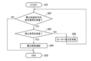
モータ制御装置1は、図4に示すように、電力供給制御手段9により電力制御を行う。
図4において、電力供給制御手段9は、電力制御のプログラムがスタートすると(301)、指令手段12から電力供給許可の指令信号を受信したかを判断する(302)。
この判断(302)がNOの場合は、プログラムをエンドにする(305)。この判断(302)がYESの場合は、監視手段15から停止信号を受信したかを判断する(303)。
この判断(303)がYESの場合は、指令手段12の指令信号を無効にしてプラス側コンタクタ7とマイナス側コンタクタ8と開放制御し、モータ2へのバッテリ3の電力供給を遮断し(304)、プログラムをエンドにする(305)。
前記判断(303)がNOの場合は、電力供給許可の指令信号に基づいてプラス側コンタクタ7とマイナス側コンタクタ8とを閉鎖し、モータ2にバッテリ3の電力を供給して(306)、判断(302)に戻る。
As shown in FIG. 4, the
In FIG. 4, when the power control program starts (301), the power supply control means 9 determines whether a power supply permission command signal is received from the command means 12 (302).
If this determination (302) is NO, the program is ended (305). If this determination (302) is YES, it is determined whether a stop signal has been received from the monitoring means 15 (303).
If this determination (303) is YES, the command signal of the command means 12 is invalidated and the
If the determination (303) is NO, the plus-
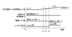
モータ制御装置1は、指令駆動力の異常判定時に、図5に示すよう動作する。
監視手段15は、指令手段12から受信した指令信号に含まれる指令駆動力と、アクセルペダルセンサ13から受信した信号に基づいて計算した推定駆動力との差Yを、監視している。
図5において、監視手段15は、T1にて指令駆動力と推定駆動力との差Yが所定値Z以上になり、差Yが所定値Z以上の状態がT2まで継続されると、指令手段12を異常と判定し、駆動制御手段6と電力供給制御手段9とに停止信号を送信する。
停止信号を受信した駆動制御手段6は、T3にてモータ2の駆動トルクをゼロとして停止する。停止信号を受信した電力供給制御手段9は、T3にてプラス側コンタクタ7とマイナス側コンタクタ8とを開放し、モータ2へのバッテリ3の電力供給を遮断する。
The
The
In FIG. 5, when the difference Y between the command driving force and the estimated driving force becomes equal to or larger than a predetermined value Z at T1, and the state where the difference Y is equal to or larger than the predetermined value Z is continued until T2, the monitoring means 15 12 is determined to be abnormal, and a stop signal is transmitted to the drive control means 6 and the power supply control means 9.
The drive control means 6 that has received the stop signal stops the drive torque of the
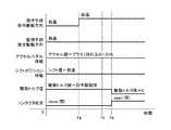
モータ制御装置1は、指令駆動方向の異常判定時に、図6に示すように動作する。
監視手段15は、指令手段12から受信した指令信号に含まれる指令駆動方向と、アクセルペダルセンサ13とシフトポジションセンサ14とから受信した信号に基づいて計算した推定駆動方向とを、監視している。
図6において、監視手段15は、T4にて指令駆動方向(後進)と推定駆動方向(前進)とが互いに異なる不一致が発生し、かつアクセルペダルの操作状態がプラス(踏み込み)方向を継続している状態がT5まで継続されると、指令手段12を異常と判定し、駆動制御手段6と電力供給制御手段9とに停止信号を送信する。
停止信号を受信した駆動制御手段6は、T6にてモータ2の駆動トルクをゼロとして停止する。停止信号を受信した電力供給制御手段9は、T6にてプラス側コンタクタ7とマイナス側コンタクタ8とを開放し、モータ2へのバッテリ3の電力供給を遮断する。
The
The
In FIG. 6, the monitoring means 15 maintains that the command drive direction (reverse) and the estimated drive direction (forward) are different from each other at T4, and the operation state of the accelerator pedal continues in the plus (depression) direction. When the current state continues until T5, the command unit 12 is determined to be abnormal, and a stop signal is transmitted to the
The drive control means 6 that has received the stop signal stops the drive torque of the
このように、モータ制御装置1は、シフトポジションセンサ14の信号に基づいて推定される推定駆動方向とモータ2の駆動を制御する指令信号に含まれる指令駆動方向とを比較し、指令駆動方向と推定駆動方向とが互いに異なる場合、モータ2の駆動を停止するので、運転者が要求する進行方向とは異なる方向へ車両が走行するのを防止できる。
モータ制御装置1は、指令駆動方向と推定駆動方向とが互いに異なる場合、指令手段12に異常が発生したと判定するので、指令手段12の異常を検出でき、かつ、電力供給制御手段9によってモータ2ヘの電力の供給を遮断するので、モータ2の駆動をより確実に停止できる。
モータ制御装置1は、指令駆動方向と推定駆動方向とが互いに異なる場合、モータ2の駆動停止ならびにモータ2ヘの電力供給の遮断を行うための停止信号を駆動制御手段6および電力供給制御手段9へ送信し、停止信号を受信した駆動制御手段6および電力供給制御手段9が指令信号に基づく指令を無効にするので、例えば指令信号が誤送信されるような状況であったとしても、モータ2の駆動を確実に停止できる。
モータ制御装置1は、推定駆動力と指令信号に含まれる指令駆動力との比較において、指令駆動力と推定駆動力との差が所定値以上の場合、もしくは、推定駆動方向と指令信号に含まれる指令駆動方向とが互いに異なる場合の少なくともいずれか一方が成立すると、駆動制御手段6によってモータ2の駆動を停止し、電力供給制御手段9によってモータ2ヘの電力の供給を遮断するので、モータ2のトルクの異常を詳細に判定でき、モータ2の駆動をより的確に停止できる。
Thus, the
When the command drive direction and the estimated drive direction are different from each other, the
When the command drive direction and the estimated drive direction are different from each other, the
When the difference between the command driving force and the estimated driving force is a predetermined value or more in the comparison between the estimated driving force and the command driving force included in the command signal, the
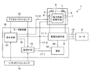
上述実施例のモータ制御装置1は、駆動制御手段6と指令手段12と監視手段15とを別体に構成したが、図7に示す変形例のモータ制御装置1のように駆動制御手段6と指令手段12と監視手段15とを一体とすることができる。
図7において、変形例のモータ制御装置1は、モータ2を駆動する電力を蓄えるバッテリ3を備え、バッテリ3の電力をモータ2に供給するプラス側電路4とマイナス側電路5とにそれぞれプラス側コンタクタ7とマイナス側コンタクタ8とを備え、プラス側コンタクタ7とマイナス側コンタクタ8とを開閉制御する電力供給制御手段9を備えている。
モータ制御装置1は、モータ2を制御するモータ制御部18を備えている。モータ制御部18は、駆動制御手段6と指令手段12と監視手段15とを一体化し、駆動制御手段6を差動するための電源19を備えている。
バッテリ3は、プラス側電路4とマイナス側電路5とを駆動制御手段6に接続している。駆動制御手段6は、三相電路10によってモータ2に接続し、モータ2の駆動を制御する。駆動制御手段6は、第1指令信号線11−1により指令手段12に接続している。電力供給制御手段9は、第2指令信号線11−2により指令手段12に接続している。指令手段12には、アクセルペダルセンサ13と、シフトポジションセンサ14とを接続している。
指令手段12は、アクセルペダルセンサ13から受信した信号とシフトポジションセンサ14から受信した信号とに基づいてモータ2の指令駆動力と指令駆動方向とを計算し、指令駆動力と指令駆動方向とを含む指令信号を第1指令信号線11−1によって駆動制御手段6に送信する。駆動制御手段6は、指令信号に基づいてモータ2の駆動を制御する。
また、指令手段12は、たとえば、イグニッションスイッチ(図示しない)のオン制御やオフ制御、車両の状態に基づき、電力供給を許可または停止するための指令信号を第2指令信号線11−2によって電力供給制御手段9に送信する。電力供給制御手段9は、指令信号に基づいてモータ2へのバッテリ3の電力の供給および遮断を制御する。
In the
In FIG. 7, the modified
The
The
The command means 12 calculates the command drive force and the command drive direction of the
Further, the command means 12 uses a second command signal line 11-2 to send a command signal for permitting or stopping power supply based on, for example, on / off control of an ignition switch (not shown) and the state of the vehicle. This is transmitted to the supply control means 9. The power supply control means 9 controls supply and interruption of the power of the
監視手段15は、アクセルペダルセンサ13と、シフトポジションセンサ14とを接続している。監視手段15は、信号入力線16によって指令手段12に接続し、指令手段12から指令信号を受信する。監視手段15は、第1信号出力線17−1によって電源19に接続し、第2信号出力線17−2によって電力供給制御手段9に接続している。電源19は、電源線20により駆動制御手段6に接続している。監視手段15は、第1信号出力線17−1と第2信号出力線17−2とによって電源20と電力供給制御手段9とに各種信号を送信する。
監視手段15は、アクセルペダルセンサ13から受信した信号に基づいてモータ2の駆動力を推定し、ポジションセンサ14から受信した信号に基づいてモータ2の駆動方向を推定する。監視手段15は、推定駆動力と指令駆動力との比較を行い、推定駆動方向と指令駆動方向との比較を行う。
監視手段15は、比較において、指令駆動力と推定駆動力との差が所定値以上の場合、または指令駆動方向と推定駆動方向とが一致しない場合の、少なくともいずれか一方が成立すると、指令手段12に異常が発生したと判定する。監視手段15は、指令手段12に異常が発生したと判定した場合、電源19と電力供給制御手段9とに停止信号を送信する。
電源19は、監視手段15から停止信号を受信すると、駆動制御回路6への電源の供給を遮断する。これにより、モータ2の駆動が停止される。また、電力供給制御手段9は、監視手段15から停止信号を受信すると、指令手段12の指令信号を無効にし、プラス側コンタクタ7とマイナス側コンタクタ8とを開放制御し、モータ2へのバッテリ3の電力供給を遮断する。
The monitoring means 15 connects the
The
When the difference between the command driving force and the estimated driving force is equal to or greater than a predetermined value or at least one of the command driving direction and the estimated driving direction does not match in the comparison, the
When the
変形例のモータ制御装置1は、駆動制御手段6と指令手段12と監視手段15とをモータ制御部18として一体化したことで構造を簡素化でき、コストダウンを果たすことができる。また、変形例のモータ制御装置1は、監視手段15からの停止信号で、駆動制御回路6への電源の供給を遮断して駆動制御回路6の作動を停止するので、モータ2の駆動を確実に停止することができる。
The
この発明は、運転者の要求する進行方向とは異なる方向へ車両が走行するのを未然に防止することができるものであり、モータによって走行可能な車両であれば、四輪車にかぎらず、二輪車や三輪車にも適用することが可能である。すなわち、この発明が適用可能な車両は、車輪の数や車輪の有無に限定されない。 This invention can prevent the vehicle from traveling in a direction different from the traveling direction requested by the driver, and is not limited to a four-wheeled vehicle, as long as the vehicle can travel by a motor. It can also be applied to motorcycles and tricycles. That is, the vehicle to which the present invention is applicable is not limited to the number of wheels or the presence or absence of wheels.
1 モータ制御装置
2 モータ
3 バッテリ
6 駆動制御手段
7 プラス側コンタクタ
8 マイナス側コンタクタ
9 電力供給制御手段
12 指令手段
13 アクセルペダルセンサ
14 シフトポジションセンサ
15 監視手段
DESCRIPTION OF
Claims (5)
Priority Applications (1)
| Application Number | Priority Date | Filing Date | Title |
|---|---|---|---|
| JP2013247521A JP2015106975A (en) | 2013-11-29 | 2013-11-29 | Motor control device |
Applications Claiming Priority (1)
| Application Number | Priority Date | Filing Date | Title |
|---|---|---|---|
| JP2013247521A JP2015106975A (en) | 2013-11-29 | 2013-11-29 | Motor control device |
Publications (1)
| Publication Number | Publication Date |
|---|---|
| JP2015106975A true JP2015106975A (en) | 2015-06-08 |
Family
ID=53436816
Family Applications (1)
| Application Number | Title | Priority Date | Filing Date |
|---|---|---|---|
| JP2013247521A Pending JP2015106975A (en) | 2013-11-29 | 2013-11-29 | Motor control device |
Country Status (1)
| Country | Link |
|---|---|
| JP (1) | JP2015106975A (en) |
Cited By (1)
| Publication number | Priority date | Publication date | Assignee | Title |
|---|---|---|---|---|
| CN111971893A (en) * | 2018-05-10 | 2020-11-20 | 欧姆龙株式会社 | Motor control device and programming device |
-
2013
- 2013-11-29 JP JP2013247521A patent/JP2015106975A/en active Pending
Cited By (1)
| Publication number | Priority date | Publication date | Assignee | Title |
|---|---|---|---|---|
| CN111971893A (en) * | 2018-05-10 | 2020-11-20 | 欧姆龙株式会社 | Motor control device and programming device |
Similar Documents
| Publication | Publication Date | Title |
|---|---|---|
| CN107482761B (en) | Power Systems | |
| JP5348662B2 (en) | Method for correcting clutch characteristics of hybrid vehicle | |
| JP2017206162A (en) | Vehicle control system | |
| JP5010288B2 (en) | Control device for hybrid vehicle | |
| JP2011110943A (en) | Controller for vehicle drive system | |
| US9457688B2 (en) | Electric driving wheel type work vehicle | |
| JP2015000718A (en) | Fail-safe control device and method for hybrid vehicle | |
| KR101348898B1 (en) | Control method for fail safety of hybrid vehicle | |
| KR20140081697A (en) | Traveling mode switching controller of hybrid electric vehicle | |
| JP2014113947A (en) | Control unit for hybrid vehicle | |
| CN102186691A (en) | Ways to Improve the Availability of Hybrid Electric Vehicles | |
| US12311773B2 (en) | Methods and systems for ensuring compliance of an electric vehicle | |
| JP5767265B2 (en) | High voltage system control device for vehicle | |
| JP2008302754A (en) | Control device for hybrid vehicle | |
| CN104192142B (en) | Start and stop control method and system for hybrid vehicle engine | |
| JP2007238009A (en) | Control device for hybrid electric vehicle | |
| WO2017145829A1 (en) | Vehicle control system | |
| KR102388275B1 (en) | In-wheel system with autonomous emergency braking utility and control method thereof | |
| JP2015106975A (en) | Motor control device | |
| WO2015146773A1 (en) | Hybrid vehicle, and control method therefor | |
| JP2016199197A (en) | Control device and control method for hybrid vehicle | |
| JP6634772B2 (en) | Stop lamp failure detection device | |
| JP5206324B2 (en) | Control device and control method for hybrid vehicle | |
| JP2016078662A (en) | Electric car | |
| JP2014155402A (en) | Motor control system of electric vehicle |