JP2015102472A - Triaxial test device and triaxial test method - Google Patents
Triaxial test device and triaxial test method Download PDFInfo
- Publication number
- JP2015102472A JP2015102472A JP2013244449A JP2013244449A JP2015102472A JP 2015102472 A JP2015102472 A JP 2015102472A JP 2013244449 A JP2013244449 A JP 2013244449A JP 2013244449 A JP2013244449 A JP 2013244449A JP 2015102472 A JP2015102472 A JP 2015102472A
- Authority
- JP
- Japan
- Prior art keywords
- load
- displacement
- cap
- pedestal
- specimen
- Prior art date
- Legal status (The legal status is an assumption and is not a legal conclusion. Google has not performed a legal analysis and makes no representation as to the accuracy of the status listed.)
- Granted
Links
- 238000012360 testing method Methods 0.000 title claims abstract description 112
- 238000010998 test method Methods 0.000 title claims description 24
- 238000006073 displacement reaction Methods 0.000 claims abstract description 157
- 230000007246 mechanism Effects 0.000 claims abstract description 126
- 238000005259 measurement Methods 0.000 claims abstract description 95
- 238000001514 detection method Methods 0.000 claims abstract description 12
- NJPPVKZQTLUDBO-UHFFFAOYSA-N novaluron Chemical compound C1=C(Cl)C(OC(F)(F)C(OC(F)(F)F)F)=CC=C1NC(=O)NC(=O)C1=C(F)C=CC=C1F NJPPVKZQTLUDBO-UHFFFAOYSA-N 0.000 claims description 82
- 230000006835 compression Effects 0.000 claims description 7
- 238000007906 compression Methods 0.000 claims description 7
- 238000005056 compaction Methods 0.000 claims description 4
- 239000000463 material Substances 0.000 abstract description 24
- 230000000007 visual effect Effects 0.000 abstract description 9
- 238000000034 method Methods 0.000 description 25
- 239000011435 rock Substances 0.000 description 17
- 238000007596 consolidation process Methods 0.000 description 11
- 230000014509 gene expression Effects 0.000 description 8
- XLYOFNOQVPJJNP-UHFFFAOYSA-N water Substances O XLYOFNOQVPJJNP-UHFFFAOYSA-N 0.000 description 8
- 230000008859 change Effects 0.000 description 6
- 238000010586 diagram Methods 0.000 description 5
- 239000011159 matrix material Substances 0.000 description 5
- 239000002689 soil Substances 0.000 description 5
- 238000011835 investigation Methods 0.000 description 4
- 239000000758 substrate Substances 0.000 description 4
- 239000000853 adhesive Substances 0.000 description 3
- 230000001070 adhesive effect Effects 0.000 description 3
- 239000002184 metal Substances 0.000 description 3
- 229910052751 metal Inorganic materials 0.000 description 3
- 239000011148 porous material Substances 0.000 description 3
- 230000008569 process Effects 0.000 description 3
- 238000005096 rolling process Methods 0.000 description 3
- 238000005070 sampling Methods 0.000 description 3
- 238000011161 development Methods 0.000 description 2
- 229920001971 elastomer Polymers 0.000 description 2
- 229910052602 gypsum Inorganic materials 0.000 description 2
- 239000010440 gypsum Substances 0.000 description 2
- 230000002093 peripheral effect Effects 0.000 description 2
- 239000004033 plastic Substances 0.000 description 2
- 238000003860 storage Methods 0.000 description 2
- 230000009466 transformation Effects 0.000 description 2
- 229910000906 Bronze Inorganic materials 0.000 description 1
- OAICVXFJPJFONN-UHFFFAOYSA-N Phosphorus Chemical compound [P] OAICVXFJPJFONN-UHFFFAOYSA-N 0.000 description 1
- 241000923606 Schistes Species 0.000 description 1
- 239000010974 bronze Substances 0.000 description 1
- 238000012790 confirmation Methods 0.000 description 1
- 238000010276 construction Methods 0.000 description 1
- KUNSUQLRTQLHQQ-UHFFFAOYSA-N copper tin Chemical compound [Cu].[Sn] KUNSUQLRTQLHQQ-UHFFFAOYSA-N 0.000 description 1
- 230000008021 deposition Effects 0.000 description 1
- 238000013461 design Methods 0.000 description 1
- 230000000694 effects Effects 0.000 description 1
- 238000011156 evaluation Methods 0.000 description 1
- 229910052500 inorganic mineral Inorganic materials 0.000 description 1
- 238000009434 installation Methods 0.000 description 1
- 238000000691 measurement method Methods 0.000 description 1
- 239000011707 mineral Substances 0.000 description 1
- 238000012986 modification Methods 0.000 description 1
- 230000004048 modification Effects 0.000 description 1
- 239000012188 paraffin wax Substances 0.000 description 1
- 239000002245 particle Substances 0.000 description 1
- 238000012545 processing Methods 0.000 description 1
- 238000011160 research Methods 0.000 description 1
- 229920002379 silicone rubber Polymers 0.000 description 1
- 238000004088 simulation Methods 0.000 description 1
- 229910001220 stainless steel Inorganic materials 0.000 description 1
- 239000010935 stainless steel Substances 0.000 description 1
Images


Abstract
Description
本発明は、三軸試験装置及び三軸試験方法に関するものであり、より詳細には、土又は岩等からなる地盤から採取した柱状供試体を三軸セル内のペデスタル及びキャップの間に介挿し、載荷装置の載荷シャフトによって供試体に軸荷重を負荷して供試体を圧密及び軸圧縮する三軸試験装置及び三軸試験方法に関するものである。 The present invention relates to a triaxial test apparatus and a triaxial test method, and more specifically, a columnar specimen collected from the ground made of soil or rock is inserted between a pedestal and a cap in a triaxial cell. The present invention relates to a triaxial test apparatus and a triaxial test method in which an axial load is applied to a specimen by a loading shaft of the loading apparatus to compact and axially compress the specimen.
地盤の変形特性や強度特性を調べるための試験装置として、原位置から採取した円柱状供試体に側圧を負荷した状態で供試体に軸荷重を負荷する三軸試験装置が知られている(例えば、特許文献1及び2)。従来の三軸試験装置の構成が図7に概略的に示されている。
As a test apparatus for examining the deformation characteristics and strength characteristics of the ground, there is known a triaxial test apparatus that applies an axial load to the specimen in a state where a side pressure is applied to the cylindrical specimen taken from the original position (for example,
図7に示す如く、三軸試験装置100は、供試体Sを収容可能な三軸セル(三軸圧力室)101を有する。三軸セル101は、底盤102、圧力円筒103及び上盤104によって形成される。供試体Sは、ペデスタル105及びキャップ106の間に配置される。供試体Sの外周面は、ゴムスリーブ107によって被覆される。載荷装置の載荷シャフト108が、上盤104を貫通し、供試体Sに軸力を負荷する。軸荷重Qを計測するための荷重計109が、載荷シャフト108に介装される。載荷シャフト108は、軸変位計120の検出部に関連した軸変位検出用ロッド121を備える。セル圧供給路111が底盤110を貫通し、底盤110の上面に開口する。セル圧供給路115が上盤104を貫通し、上盤104の下面に開口する。多孔質板(ポーラスストーン)114、115が供試体Sの上面及び下面に配置され、管路112、113を介して二重管ピューレット122、間隙水圧系123等に接続される。三軸試験装置100は更に、セル圧供給装置、載荷枠、載荷装置等(図示せず)を備えるとともに、計測データを処理する記録装置、記憶装置、表示装置等の外部制御装置又は外部制御系(図示せず)を備える。
As shown in FIG. 7, the
このような三軸試験装置を用いて地盤材料の変形特性の異方性を調べる三軸試験においては、図8に示す如く、異なるサンプリング方向のコアKを地盤Jから採取し、各コアKを供試体Sとしてペデスタル105及びキャップ106の間に配置し、各供試体Sに生じる歪みを多方向計測しながら三軸試験する試験方法が採用されてきた(非特許文献1)。
In the triaxial test for examining the anisotropy of the deformation characteristics of the ground material using such a triaxial testing apparatus, as shown in FIG. 8, the cores K in different sampling directions are sampled from the ground J, and each core K is obtained. A test method has been adopted in which the specimen S is arranged between the
また、面内等方性を仮定した線形弾性体に関する異方性の調査においては、異なるサンプリング方向で採取された3個以上の角柱供試体を三軸試験装置にセットし、歪みを多方向計測しながら各供試体を三軸試験することにより、5つの弾性パラメータを特定する手法が提案されている(非特許文献2)。更に、同様の手法で円柱供試体を用いた場合の歪み計測方法が提案されている(非特許文献3)。 In addition, in the investigation of anisotropy for linear elastic bodies assuming in-plane isotropic properties, three or more prismatic specimens collected in different sampling directions are set in a triaxial test apparatus, and strain is measured in multiple directions. However, a method of specifying five elastic parameters by performing a triaxial test on each specimen is proposed (Non-Patent Document 2). Furthermore, a strain measurement method using a cylindrical specimen by a similar method has been proposed (Non-Patent Document 3).
しかしながら、地盤材料の力学特性に関する異方性を、三軸試験装置を用いて調査する従来の調査方法には、以下の如き課題が内在する。 However, the following problems are inherent in the conventional investigation method for examining the anisotropy related to the mechanical properties of the ground material using a triaxial testing apparatus.
(1)三軸載荷時に発生する異方性材料特有の変形及び応力を考慮し又は特定することができない。
図9(A)は、等方性材料からなる供試体Sの三軸載荷時の圧密変形態様を概略的に示す斜視図であり、図9(B)は、異方性材料(面内等方性材料)からなる供試体Sの三軸載荷時の圧密変形態様を示す概略斜視図である。
(1) The deformation and stress peculiar to anisotropic materials generated at the time of triaxial loading cannot be considered or specified.
FIG. 9 (A) is a perspective view schematically showing a consolidation deformation mode at the time of triaxial loading of the specimen S made of an isotropic material, and FIG. 9 (B) shows an anisotropic material (in-plane etc. It is a schematic perspective view which shows the compaction deformation mode at the time of triaxial loading of the test body S which consists of an anisotropic material).
図9(A)に示す等方性材料の供試体Sを載荷試験する場合、軸対称条件が満たされ、従って、主応力方向と主歪み方向とが一致するので、供試体Sは、軸方向に均等に圧縮する。これに対し、異方性材料の供試体Sを載荷する場合、軸対称条件が必ずしも満たされず、従って、主応力方向と主歪み方向が一致しない。このため、異方性材料の供試体Sの載荷試験において、供試体Sの変形を拘束しない条件で載荷すると、図9(B)に示す如く、剛性の等方な面の傾斜方向に剪断変形が発生する。例えば、面内等方弾性体として軟岩を想定した本発明者等のシミュレーションによれば、材料の異方性に起因した供試体Sの挙動が発生すると考えられる。 When the specimen S of the isotropic material shown in FIG. 9A is subjected to a loading test, the axial symmetry condition is satisfied, and therefore the principal stress direction and the principal strain direction coincide with each other. Compress evenly. On the other hand, when the specimen S of anisotropic material is loaded, the axial symmetry condition is not always satisfied, and therefore the main stress direction and the main strain direction do not match. For this reason, in the loading test of the specimen S of anisotropic material, when loading is performed under the condition that does not restrain the deformation of the specimen S, as shown in FIG. Will occur. For example, according to the simulation of the present inventors assuming soft rock as the in-plane isotropic elastic body, it is considered that the behavior of the specimen S due to the material anisotropy occurs.
このような供試体Sの変形又は挙動は、異方性材料特有の挙動であり、試料の異方性を特定する上で重要な要素である。しかしながら、従来の載荷試験においては、このような変形を計測して材料の異方性を特定することは行われていない。 Such deformation or behavior of the specimen S is a behavior peculiar to anisotropic materials, and is an important factor in specifying the anisotropy of the sample. However, in the conventional loading test, it is not performed to specify the anisotropy of the material by measuring such deformation.
また、従来の三軸試験においては、供試体Sを拘束するキャップが軸方向にのみ変位し得るにすぎず、異方性を有する面内等方性材料の供試体Sの載荷試験であっても、供試体Sは、軸方向にのみ圧密変形し得るにすぎない。即ち、従来の三軸試験装置においては、軸力方向と交差又は直交する方向(側方向)に生じ得る供試体Sの変位が禁止又は拘束されるので、剛性が等方な面の傾斜方向に剪断応力が作用する。この種の剪断応力は材料の異方性に起因する異方性材料特有の応力であり、材料の異方性を特定する上で重要な要素であるが、従来の載荷試験においては、このような剪断応力を計測することは、試みられていない。 Moreover, in the conventional triaxial test, the cap that restrains the specimen S can only be displaced in the axial direction, and is a loading test of the specimen S of in-plane isotropic material having anisotropy. However, the specimen S can only be deformed only in the axial direction. That is, in the conventional triaxial test apparatus, the displacement of the specimen S that can occur in the direction (side direction) intersecting or orthogonal to the axial force direction is prohibited or restrained. Shear stress acts. This kind of shear stress is a stress peculiar to anisotropic materials due to the material anisotropy, and is an important factor in specifying the material anisotropy. No attempt has been made to measure the shear stress.
(2)異方性の方向を特定することができない。
変形特性の異方性を調べる従来の調査手法においては、岩石コア等を目視観察して異方性の方向を推定した上で載荷試験が実施される。このような調査手法によれば、異方性の方向は、堆積面や節理の方向、或いは、鉱物粒子が配向する方向等に基づいて仮定されるが、例えば、複数の方向に卓越する節理を有する岩石等については、目視観察によって異方性の方向を特定することはできない。
(2) The direction of anisotropy cannot be specified.
In the conventional investigation method for examining the anisotropy of deformation characteristics, a loading test is performed after the direction of anisotropy is estimated by visually observing a rock core or the like. According to such a survey method, the direction of anisotropy is assumed based on the deposition surface, the direction of joints, the direction in which mineral particles are oriented, etc. About the rock etc. which have, the direction of anisotropy cannot be specified by visual observation.
(3)多数回の載荷試験を要する。
最も簡易な変形特性の異方性である面内等方性を仮定した調査においても、少なくとも3方向にサンプリングしたコアを用いた試験が必要とされる。試験結果のばらつきを考慮すると、更に試験回数を増大する必要があり、この結果、比較的高額の試験費用や、長い試験時間を要する。
(3) Many loading tests are required.
Even in the study assuming in-plane isotropic, which is the simplest anisotropy of deformation characteristics, a test using a core sampled in at least three directions is required. Considering variation in test results, it is necessary to further increase the number of tests. As a result, a relatively high test cost and a long test time are required.
本発明は、このような事情に鑑みてなされたものであり、その目的とするところは、土や岩等からなる地盤から採取した柱状供試体を用いた単一回又は少数回の三軸試験によって、異方性に起因した供試体の変形又は応力を測定又は計測し、これにより、地盤材料の変形特性の異方性を特定するとともに、目視観察に依存せずに異方性の方向を特定することができる三軸試験装置及び三軸試験方法を提供することにある。 The present invention has been made in view of such circumstances, and its purpose is to perform a single or a small number of triaxial tests using a columnar specimen collected from the ground made of soil or rock. To measure or measure the deformation or stress of the specimen due to anisotropy, thereby identifying the anisotropy of the deformation characteristics of the ground material and determining the direction of anisotropy without depending on visual observation. An object of the present invention is to provide a triaxial test apparatus and a triaxial test method that can be specified.
上記目的を達成すべく、本発明は、地盤から採取した柱状供試体を収容する三軸セルを備え、ペデスタル及びキャップによって拘束された三軸セル内の前記供試体に対し、載荷装置の載荷シャフトによって軸荷重を負荷して該供試体を圧密及び軸圧縮する三軸試験装置において、
前記キャップは、前記載荷シャフトと、前記供試体の頂部に配置されたキャップ本体との間に介装した変位計測式キャップ機構及び/又は荷重計測式キャップ機構を有し、
前記変位計測式キャップ機構は、軸荷重の載荷時に前記キャップ本体の側方変位又は水平変位を許容する可動手段を有し、
前記荷重計測式キャップ機構は、前記軸荷重の載荷時に前記キャップ本体の側方変位又は水平変位を禁止し又は拘束するとともに、該軸荷重により前記キャップに作用し且つ前記軸荷重の軸力方向と交差又は直交する方向に作用する剪断応力を検出する応力検出手段を有することを特徴とする三軸試験装置を提供する。
In order to achieve the above object, the present invention includes a triaxial cell that accommodates a columnar specimen collected from the ground, and the loading shaft of the loading apparatus with respect to the specimen in the triaxial cell constrained by a pedestal and a cap. In a three-axis test apparatus for applying a shaft load to compress the specimen and compress the shaft,
The cap has a displacement measurement type cap mechanism and / or a load measurement type cap mechanism interposed between the load shaft described above and a cap main body disposed on the top of the specimen,
The displacement measuring type cap mechanism has movable means for allowing lateral displacement or horizontal displacement of the cap body when an axial load is loaded,
The load-measuring cap mechanism prohibits or restrains lateral displacement or horizontal displacement of the cap body when the axial load is loaded, and acts on the cap by the axial load and the axial force direction of the axial load. There is provided a triaxial test apparatus having stress detection means for detecting a shear stress acting in a crossing or orthogonal direction.
本発明は又、地盤から採取した柱状供試体を収容する三軸セルを備え、ペデスタル及びキャップによって拘束された三軸セル内の前記供試体に対し、載荷装置の載荷シャフトによって軸荷重を負荷して該供試体を圧密及び軸圧縮する三軸試験装置において、
前記ペデスタルは、変位計測式ペデスタル機構及び/又は荷重計測式ペデスタル機構を有し、
前記変位計測式ペデスタル機構は、軸荷重の載荷時に前記ペデスタル本体の側方変位又は水平変位を許容する可動手段を有し、
前記荷重計測式ペデスタル機構は、前記軸荷重の載荷時に前記ペデスタル本体の側方変位又は水平変位を禁止し又は拘束するとともに、該軸荷重により前記ペデスタルに作用し且つ前記軸荷重の軸力方向と交差又は直交する方向に作用する剪断応力を検出する応力検出手段を有することを特徴とする三軸試験装置を提供する。
The present invention also includes a triaxial cell that accommodates a columnar specimen collected from the ground, and an axial load is applied to the specimen in the triaxial cell constrained by a pedestal and a cap by a loading shaft of a loading device. In a triaxial testing apparatus for compacting and axially compressing the specimen,
The pedestal has a displacement measurement type pedestal mechanism and / or a load measurement type pedestal mechanism,
The displacement measuring pedestal mechanism has movable means that allows lateral displacement or horizontal displacement of the pedestal body when an axial load is loaded,
The load measurement type pedestal mechanism prohibits or restrains a lateral displacement or a horizontal displacement of the pedestal body when the axial load is loaded, and acts on the pedestal by the axial load and an axial force direction of the axial load. There is provided a triaxial test apparatus having stress detection means for detecting a shear stress acting in a crossing or orthogonal direction.
他の観点より、本発明は、地盤から採取した柱状供試体を三軸セル内に収容して、ペデスタル及びキャップによって拘束し、載荷装置の載荷シャフトによって前記供試体に軸荷重を負荷して該供試体を圧密及び軸圧縮する三軸試験方法において、
前記供試体の頂部に配置されたキャップ本体と載荷シャフトとの間に変位計測式キャップ機構又は荷重計測式キャップ機構を介装し、
軸荷重の載荷時に前記キャップ本体の側方変位又は水平変位を前記変位計測式キャップ機構により許容して、前記載荷シャフトに対する前記キャップ本体の側方変位又は水平変位を検出し、或いは、軸荷重の載荷時に前記キャップ本体の側方変位又は水平変位を禁止又は拘束した状態で該軸荷重により前記キャップに作用し且つ前記軸荷重の軸力方向と交差又は直交する方向に作用する剪断応力を前記荷重計測式キャップ機構によって検出することを特徴とする三軸試験方法を提供する。
From another point of view, the present invention includes a columnar specimen collected from the ground in a triaxial cell, restrained by a pedestal and a cap, and applies an axial load to the specimen by a loading shaft of a loading device. In the triaxial test method in which the specimen is compacted and axially compressed,
A displacement measurement type cap mechanism or a load measurement type cap mechanism is interposed between the cap body and the loading shaft arranged at the top of the specimen,
The lateral displacement or horizontal displacement of the cap body is allowed by the displacement measuring type cap mechanism when the axial load is loaded, and the lateral displacement or horizontal displacement of the cap body with respect to the load shaft described above is detected, or the axial load is detected. A shear stress acting on the cap by the axial load and acting in a direction intersecting or orthogonal to the axial force direction of the axial load in a state where lateral displacement or horizontal displacement of the cap body is prohibited or restrained at the time of loading is applied to the load. A triaxial test method characterized by detecting by a measuring cap mechanism.
本発明は更に、地盤から採取した柱状供試体を三軸セル内に収容して、ペデスタル及びキャップによって拘束し、載荷装置の載荷シャフトによって前記供試体に軸荷重を負荷して該供試体を圧密及び軸圧縮する三軸試験方法において、
前記供試体の底部に配置されたペデスタルに変位計測式ペデスタル機構又は荷重計測式ペデスタル機構を配設し又は組込み、
軸荷重の載荷時にペデスタル本体の側方変位又は水平変位を前記変位計測式ペデスタル機構により許容して、前記載荷シャフトに対する前記ペデスタル本体の側方変位又は水平変位を検出し、或いは、軸荷重の載荷時に前記ペデスタル本体の側方変位又は水平変位を禁止又は拘束した状態で該軸荷重により前記ペデスタルに作用し且つ前記軸荷重の軸力方向と交差又は直交する方向に作用する剪断応力を前記荷重計測式ペデスタル機構によって検出することを特徴とする三軸試験方法を提供する。
The present invention further includes accommodating a columnar specimen taken from the ground in a triaxial cell, constraining it by a pedestal and a cap, and applying an axial load to the specimen by a loading shaft of a loading device to consolidate the specimen. And in the triaxial test method for axial compression,
Displacement measurement type pedestal mechanism or load measurement type pedestal mechanism is installed in or built into the pedestal arranged at the bottom of the specimen,
When the axial load is loaded, the lateral displacement or horizontal displacement of the pedestal body is allowed by the displacement measurement type pedestal mechanism, and the lateral displacement or horizontal displacement of the pedestal body with respect to the load shaft described above is detected, or the loading of the axial load is performed. Measurement of the shear stress acting on the pedestal by the axial load and in the direction intersecting or orthogonal to the axial force direction of the axial load with the lateral or horizontal displacement of the pedestal body prohibited or constrained. A triaxial test method characterized by detecting by a pedestal mechanism.
本発明の上記構成によれば、変位計測式キャップ機構及び荷重計測式キャップ機構の少なくとも一方が載荷試験装置内のキャップに設けられ、或いは、変位計測式ペデスタル機構及び荷重計測式ペデスタル機構の少なくとも一方が載荷試験装置内のペデスタルに設けられる。変位計測式キャップ機構又は変位計測式ペデスタル機構を用いた三軸試験においては、軸荷重の載荷時にキャップ本体又はペデスタル本体の側方変位又は水平変位が許容されるので、異方性に起因した供試体固有の変形が発生する。供試体の変形は、載荷シャフトとキャップ本体との相対的な側方変位又は水平変位、或いは、底盤とペデスタル本体との相対的な側方変位又は水平変位として顕れる。また、荷重計測式キャップ機構又は荷重計測式ペデスタル機構を用いた三軸試験においては、キャップ本体又はペデスタル本体の側方変位又は水平変位が禁止又は拘束され、従って、供試体端面の側方への移動も禁止又は拘束されるので、異方性材料固有の剪断応力が軸荷重の軸力方向と交差又は直交する方向に供試体端面とキャップ又はペデスタルとに作用する。 According to the above configuration of the present invention, at least one of the displacement measurement type cap mechanism and the load measurement type cap mechanism is provided on the cap in the loading test apparatus, or at least one of the displacement measurement type pedestal mechanism and the load measurement type pedestal mechanism. Is provided on the pedestal in the loading test apparatus. In a triaxial test using a displacement measurement type cap mechanism or displacement measurement type pedestal mechanism, lateral displacement or horizontal displacement of the cap body or pedestal body is allowed when an axial load is loaded. Deformation specific to the specimen occurs. The deformation of the specimen appears as relative lateral displacement or horizontal displacement between the loading shaft and the cap body, or relative lateral displacement or horizontal displacement between the bottom plate and the pedestal body. Further, in the triaxial test using the load measuring type cap mechanism or the load measuring type pedestal mechanism, lateral displacement or horizontal displacement of the cap body or pedestal body is prohibited or restrained. Since the movement is also prohibited or constrained, the shear stress inherent in the anisotropic material acts on the specimen end face and the cap or pedestal in a direction crossing or perpendicular to the axial force direction of the axial load.
従って、上記構成の三軸試験装置及び三軸試験方法によれば、載荷シャフトに対するキャップ本体又はペデスタル本体の相対的な側方変位又は水平変位を計測又は測定し、或いは、キャップ又はペデスタルに作用する剪断応力を計測又は測定することにより、異方性に起因した供試体の変形及び応力を知得又は把握し、目視観察に依存せずに供試体の異方性の方向を特定することができる。 Therefore, according to the three-axis test apparatus and the three-axis test method configured as described above, the relative lateral displacement or horizontal displacement of the cap body or pedestal body with respect to the loading shaft is measured or measured, or acts on the cap or pedestal. By measuring or measuring the shear stress, the deformation and stress of the specimen due to anisotropy can be known or grasped, and the anisotropy direction of the specimen can be specified without depending on visual observation. .
また、上記構成の三軸試験装置及び三軸試験方法によれば、多数の供試体を用いて三軸試験を反復実施することなく、単一又は少数の供試体を用いた単一回又は少数回の三軸試験により、異方性に起因した供試体の変形及び応力を知得又は把握し、これにより、変形特性の異方性を調べることができる。 Further, according to the triaxial test apparatus and the triaxial test method having the above-described configuration, a single or a small number of specimens can be used once or a small number of times without repeating the triaxial test using a large number of specimens. Through the three-axis test, the deformation and stress of the specimen caused by anisotropy can be known or grasped, and thereby the anisotropy of deformation characteristics can be examined.
好ましくは、変位計測式キャップ機構又は変位計測式ペデスタル機構は、載荷シャフトと一体化した第1部材と、キャップ本体又はペデスタル本体と一体化した第2部材と、第1及び第2部材の間に介装され、第1及び第2部材を相対変位させる上記可動手段とを有する。更に好ましくは、変位計測式キャップ機構又は変位計測式ペデスタル機構は、第1及び第2部材の間に介装した第3部材を更に有し、可動手段は、第1部材及び第3部材の間に介装されるともに、第2部材と第3部材との間に介装される。第3部材の可動方向と、第3部材に対する第2部材の可動方向とは、載荷シャフトの中心軸線廻りに所定の角度間隔を隔てており、キャップ本体又はペデスタル本体は、載荷シャフトの中心軸線廻りの任意の角度方向に変位する。 Preferably, the displacement measurement type cap mechanism or the displacement measurement type pedestal mechanism includes a first member integrated with the loading shaft, a second member integrated with the cap body or the pedestal body, and the first and second members. And the above-mentioned movable means for interposing and relatively displacing the first and second members. More preferably, the displacement measurement type cap mechanism or the displacement measurement type pedestal mechanism further includes a third member interposed between the first and second members, and the movable means is between the first member and the third member. And is interposed between the second member and the third member. The movable direction of the third member and the movable direction of the second member relative to the third member are separated from each other by a predetermined angular interval around the central axis of the loading shaft, and the cap body or the pedestal body is around the central axis of the loading shaft. Displace in any angular direction.
本発明の好適な実施形態において、上記可動手段は、転動要素、滑動要素又は摺動要素を有する支承装置を有する。好ましくは、可動手段は、多数の転動要素を有するローラ式又はボール式ベアリング装置からなる。 In a preferred embodiment of the present invention, the movable means has a bearing device having a rolling element, a sliding element or a sliding element. Preferably, the movable means comprises a roller or ball bearing device having a number of rolling elements.
好適には、変位計測式キャップ機構又は変位計測式ペデスタル機構は、軸荷重の載荷時に生じる供試体端面(上端面又は下端面)の変位をキャップ本体又はペデスタル本体の側方変位又は水平変位と同一であると仮定して、キャップ本体又はペデスタル本体の側方変位又は水平変位を検出する変位検出手段を有する。また、荷重計測式キャップ機構又は荷重計測式ペデスタル機構は、供試体端面に作用する剪断応力を検出する2方向ロードセルを有する。2方向ロードセルは、方向が異なる少なくとも二方向に作用する剪断応力を検出する。2方向ロードセルとして、平行平板型ロードセルを好ましく使用し得る。供試体の異方性は、供試体の端面ないしキャップ又はペデスタルの側方変位又は水平変位の変位量、或いは、供試体の端面に作用する剪断応力に基づいて特定される。 Preferably, the displacement measuring type cap mechanism or the displacement measuring type pedestal mechanism is such that the displacement of the end face (upper end face or lower end face) of the specimen that occurs when the axial load is loaded is the same as the lateral displacement or horizontal displacement of the cap body or pedestal body. It is assumed that the displacement detection means for detecting a lateral displacement or a horizontal displacement of the cap body or the pedestal body is provided. Further, the load measurement type cap mechanism or the load measurement type pedestal mechanism has a two-way load cell that detects a shear stress acting on the end face of the specimen. A bi-directional load cell detects shear stress acting in at least two different directions. As the two-way load cell, a parallel plate type load cell can be preferably used. The anisotropy of the specimen is specified based on the amount of lateral displacement or horizontal displacement of the end face or cap or pedestal of the specimen, or the shear stress acting on the end face of the specimen.
本発明の三軸試験装置及び三軸試験方法によれば、土や岩等からなる地盤から採取した柱状供試体を用いた単一回又は少数回の三軸試験によって、異方性に起因した供試体の変形又は応力を測定又は計測し、これにより、地盤材料の変形特性の異方性を特定するとともに、目視観察に依存せずに異方性の方向を特定することができる。 According to the triaxial test apparatus and the triaxial test method of the present invention, the single axis or a small number of triaxial tests using columnar specimens collected from the ground made of soil, rock, etc. caused the anisotropy. The deformation or stress of the specimen is measured or measured, whereby the anisotropy of the deformation characteristics of the ground material can be specified, and the anisotropy direction can be specified without depending on visual observation.
以下、添付図面を参照して、本発明の好適な実施例について詳細に説明する。 Hereinafter, preferred embodiments of the present invention will be described in detail with reference to the accompanying drawings.
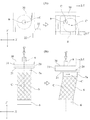
図1及び図2は、本発明に係る三軸試験装置の構造を概略的に示す縦断面図である。 1 and 2 are longitudinal sectional views schematically showing the structure of a triaxial test apparatus according to the present invention.
三軸試験装置1は、供試体Sを収容可能な三軸セル(三軸圧力室)2を有する。三軸セル2は、底盤3、圧力円筒4及び上盤5によって形成される。供試体Sは、ペデスタル6及びキャップ7の間に配置される。供試体Sの外周面は、ゴムスリーブ8によって被覆される。供試体Sに軸荷重Qを負荷する載荷シャフト(又は載荷ロッド)9が上盤5の軸受部5aを貫通する。載荷シャフト9は、油圧シリンダ装置等からなる載荷装置の駆動源に連結される。
The
軸荷重Qを計測するための荷重計(ロードセル)10が、載荷シャフト9に介装される。セル圧供給装置を構成するセル圧供給路11が底盤3を貫通し、底盤3の上面に開口する。セル圧供給路12が上盤5を貫通し、上盤5の下面に開口する。セル圧供給路12は、セル圧供給装置を構成するコンプレッサ等の圧力源に接続される。所定水位のセル水Wが三軸セル2内に貯留される。空気供給路12を介して供給されるセル圧供給装置のセル圧がセル水Wの水圧に変換される。
A load cell (load cell) 10 for measuring the axial load Q is interposed in the
多孔質板(ポーラスストーン)13、14が供試体Sの上面及び下面に配置される。多孔質板13、14は、管路15、16を介して排水条件制御回路及び背圧供給装置(図示せず)に接続される。三軸試験装置1は更に、管路16に接続された体積変化測定用の間隙水圧計62及び二重管ピューレット63等を備える。
Porous plates (porous stones) 13 and 14 are disposed on the upper and lower surfaces of the specimen S, respectively. The
三軸試験においては、載荷装置の出力が軸荷重Qとして載荷シャフト9に作用し、載荷シャフト9は、キャップ7を介して軸荷重Qを供試体Sに付与する。軸荷重Qは荷重計10によって計測される。載荷シャフト9は、軸変位計60の検出部に関連した軸変位検出用ロッド61を備える。供試体Sの軸方向変位及び体積変化が軸変位計60、間隙水圧計62及び二重管ピューレット63によって計測又は測定される。各計測装置の計測データは、制御信号線(図示せず)を介して記録装置、記憶装置、表示装置等を含む外部制御装置又は外部制御系(図示せず)に入力される。また、供試体Sの外側面には、複数の歪みゲージGを取付けることができる。各歪みゲージGは、制御信号線(図示せず)を介して外部制御装置又は外部制御系に接続される。
In the triaxial test, the output of the loading device acts on the
本発明に係る三軸試験装置1においては、地盤材料の変形特性の異方性を特定するための以下の2つの方式のキャップ機構のいずれか一方が三軸セル2に配設される。即ち、第1方式のキャップ機構は、キャップ7を側方変位可能に構成し、異方性に起因する変形の計測を可能にする変位計測式キャップ機構であり、第2方式のキャップ機構は、異方性に起因する剪断応力の計測又は測定を可能にする荷重計測式キャップ機構である。なお、荷重計測式キャップ機構を備えたキャップ7の変位条件は、通常の三軸試験と同等の変位条件(即ち、側方変位を許容せず、載荷シャフト9の軸線方向の変位のみを許容する変位条件)と同一である。
In the
変位計測式キャップ機構は、供試体Sの異方性に起因するキャップ7の側方変位又は水平変位を計測するためのものであり、荷重計測式キャップ機構は、供試体Sの異方性に起因してキャップ7に作用する剪断応力を計測又は測定するためのものである。いずれの機構によっても、単一(1回)の三軸試験によって供試体Sの異方性を調査することが可能となる。
The displacement measurement type cap mechanism is for measuring the lateral displacement or horizontal displacement of the
図1に示す三軸試験装置1においては、変位計測式キャップ機構17を備えたキャップ7が三軸セル2に配設される。他方、図2に示す三軸試験装置1においては、荷重計測式キャップ機構18を備えたキャップ7が三軸セル2に配設される。図1に示す三軸試験装置1を第1実施例(実施例1)として以下に説明し、図2に示す三軸試験装置1を第2実施例(実施例2)として以下に説明する。
In the
図1に示す三軸試験装置1において、キャップ7の変位計測式キャップ機構17は、キャップ7のキャップ本体7aと載荷シャフト9の下端部との間に介装される。
In the
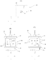
図3は、変位計測式キャップ機構17の構造を示す平面図、正面図及び側面図である。
FIG. 3 is a plan view, a front view, and a side view showing the structure of the displacement measuring
変位計測式キャップ機構17は、載荷シャフト9の中心軸線方向(Z軸方向)と直交する側方向(X軸方向)に変位可能な第1キャリッジ20と、Z軸及びX軸と直交する側方向(Y軸方向)に変位可能な第2キャリッジ30と、キャップ本体7aの上面に固定され且つ第1キャリッジ20をX軸方向に変位可能に支承する第1レール21と、第1キャリッジ20の上面に固定され且つ第2キャリッジ30をY軸方向に変位可能に支承する第2レール31とから構成される。第2キャリッジ30の上面中心部には、載荷シャフト9の下端部が固定される。キャリッジ20、30及びレール21、31は夫々、一体的に成形された高剛性の金属製部材、例えば、ステンレススチール製部材からなる。
The displacement measurement
キャリッジ20、30は、レール21、31を部分的に収容可能な下面開放形の凹所20a、30aを有する。キャリッジ20、30とレール21、31との間には、多数の金属ローラ又は金属ボールを配列してなるローラ式又はボール式ベアリング装置23、33が介装される。ベアリング装置23は、キャップ本体7aに対して第1キャリッジ20をX軸方向に相対変位させ、ベアリング装置33は、第1キャリッジ20に対してキャリッジ30をY軸方向に相対変位させる。従って、載荷シャフト9の下端部とキャップ本体7aとは、図3(A)に示すXY平面上で任意の方向に相対変位することができる。キャリッジ20、30、レール21、31及びベアリング装置23、33として、例えば、日本精工株式会社製のNSKリニアガイド(登録商標)等の機構を好適に使用し得る。
The
図4は、異方性を有する供試体Sの三軸試験において生じる変位計測式キャップ機構17の挙動を例示する平面図及び側面図である。
FIG. 4 is a plan view and a side view illustrating the behavior of the displacement measurement
図4に示す如く、載荷シャフト9によって軸荷重Qを供試体Sに載荷すると、キャップ本体7aは、供試体Sの圧密変形に相応して降下するとともに、異方性に起因した供試体Sの変形に相応してX軸方向及びY軸方向に変位する。X軸方向におけるキャップ本体7aの変位は、第1キャリッジ20に対する第1レール21の相対変位により発生する。Y軸方向におけるキャップ本体7aの変位は、第2キャリッジ30に対する第2レール31の相対変位により発生する。即ち、変位計測式キャップ機構17は、供試体Sの剪断変形に追従してキャップ本体7aをXY平面の面内方向に変位させるので、キャップ本体7aの中心軸線Cは、X軸方向及びY軸方向に変位し、位置C'に移動する。
As shown in FIG. 4, when the axial load Q is loaded on the specimen S by the
キャリッジ20、30とレール21、31との間に発生する摩擦は、ベアリング装置23、33の存在により実質的に無視し得るので、三軸試験装置1は、供試体Sに剪断応力が発生しない条件で供試体Sの端面に載荷し、供試体Sを剪断変形させることができる。なお、キャップ本体7aが供試体Sの剪断変形に確実に追随すべく、好ましくは、相互接触する供試体Sの端面、キャップ本体7aの表面及びペデスタル6の表面が粗の摩擦条件に設定され、或いは、これらの部分が石膏、接着剤等によって互いに固定される。
Since the friction generated between the
図4に概念的に示す如く、変位計測式キャップ機構17は、キャリッジ20、30の水平変位量ΔX、ΔYを検出する第1変位計22及び第2変位計32を備える。第1変位計22は、第1レール21に対する第1キャリッジ20のY方向変位を検出し、第2変位計32は、第2レール31に対する第2キャリッジ30のX方向変位を検出する。変位計22、32の検出結果は、制御信号線(図示せず)を介して前述の外部制御装置又は外部制御系に入力される。なお、渦電流式又は接触式の変位計等が変位計22、32として用いられ、変位計22、32の検知部は、レール21、31の変位(即ち、供試体Sの異方性に起因する変形)を計測するようにセル三軸セル2の適所に配置される。
As conceptually shown in FIG. 4, the displacement measurement
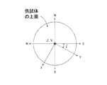
図5は、歪みゲージGの配置を示す平面図及び展開図である。 FIG. 5 is a plan view and a development view showing the arrangement of the strain gauges G.
歪みゲージGは、試験を実施する現場において、地理座標系(E、W、S、N)に対して、供試体Sの外側面に図5に示す如く配置される。各歪みゲージGは、接着剤等によって供試体Sの外側面に接着される。パラフィン又はシリコンゴム等で各歪みゲージGのプレート表面を止水することが望ましい。図5に示す番号1〜6の歪みゲージGに関し、i番目の歪みゲージ42によって計測される歪みをxiとすると、地理座標系の歪みテンソル成分は下記の数式1で計算することができる.

なお、γijは工学歪みであり、工学歪みγijとテンソル歪みεijとの間には、γij=εij (i≠j) (i、j=S、E、V)の関係がある。 Γ ij is an engineering strain, and there is a relationship of γ ij = ε ij (i ≠ j) (i, j = S, E, V) between the engineering strain γ ij and the tensor strain ε ij .
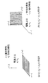
次に、荷重計測式キャップ機構18をキャップ7に備えた三軸試験装置1の実施例に関し、図2及び図6を参照して説明する。
Next, an embodiment of the
キャップ7の荷重計測式キャップ機構18は、キャップ7のキャップ本体7aと載荷シャフト9の下端部との間に介装される。荷重計測式キャップ機構18は、供試体Sの中心軸線方向(Z軸方向)に直交する2方向(X軸方向及びY軸方向)の剪断応力を計測する平行平板型の2方向ロードセル50を有する。本例においては、供試体Sの剪断変形を禁止又は拘束すべく、供試体Sとキャップ本体7aとの間の滑りを防止する必要があるので、供試体Sの上端面と相互接触する供試体Sの端面、キャップ本体7aの表面及びペデスタル6の表面が粗の摩擦条件に設定され、或いは、これらの部分が石膏、接着剤等によって互いに固定される。
The load measuring
図6は、荷重計測式キャップ機構18の構造を示す平面図、正面図及び側面図である。
FIG. 6 is a plan view, a front view, and a side view showing the structure of the load measuring
荷重計測式キャップ機構18は、キャップ本体7aの上面に固定された基板40と、基板40に固定された2方向ロードセル50と、2方向ロードセル50の上面に固定された頂板43とから構成される。頂板43の上面には、載荷シャフト9の下端部が固定される。基板40、2方向ロードセル50及び頂板43は、載荷シャフト9の中心軸線に対して同心状に整列配置される。
The load measuring
2方向ロードセル50は、Y軸方向及びX軸方向に延びる方形断面の開口部51、52を有する。開口部51の下側及び上側に位置する平板53、54は、X軸方向の応力を測定するための平行平板を構成し、開口部52の下側及び上側に位置する平板54、55は、Y軸方向の応力を測定するための平行平板を構成する。基板40、2方向ロードセル50及び頂板43は、例えば、弾性が卓越するりん青銅からなり、互いに剛接される。
The two-
2方向ロードセル50の外側面には、X軸方向に延びる複数の歪みゲージ57と、Y方向に延びる複数の歪みゲージ58とが所定位置に取付けられる。各歪みゲージ57、58は、制御信号線(図示せず)を介して前述の外部制御装置又は外部制御系(図示せず)に接続される。載荷シャフト9によって軸荷重Qを供試体Sに載荷すると、外部制御装置又は外部制御系は、歪みゲージ57、58の電気抵抗の変化に基づいてX軸方向及びY軸方向の剪断荷重を計測することができる。なお、供試体Sの端面に作用する剪断応力の平均値は、計測された剪断荷重を供試体端面の面積で除した値として求められる。
A plurality of
載荷試験は、供試体Sの剪断変形が発生しない条件で実施されるので、一般的な三軸試験における載荷条件と同等である。しかしながら、三軸試験装置1は、異方性に起因する剪断応力を荷重計測式キャップ機構18により計測することができるので、供試体Sの変形特性の異方性を特定することが可能となる。なお、軸荷重Qは、荷重計10によって計測される。所望により、セル外に配置した外部荷重計(ロードセル)によって軸荷重Qを計測することも可能であるが、上盤5の軸受部5aにおいて載荷シャフト9が摩擦力を受ける場合があるので、事前のキャリブレーションにより外部荷重計の計測値を補正することが望ましい。また、供試体Sの歪みは、図5に示す如く供試体Sの外面に取付けた歪みゲージGによって計測される。
Since the loading test is performed under the condition that shear deformation of the specimen S does not occur, it is equivalent to the loading condition in a general triaxial test. However, since the
以上、変位計測式キャップ機構17を備えた三軸試験装置1を実施例1として説明し、荷重計測式キャップ機構18を備えた三軸試験装置1を実施例2として説明したが、いずれかの機構を備えた三軸試験装置1は、不連続面等を含み且つ軸対称条件を満たさないと想定される性状の供試体Sの三軸試験に有効に用いられる。このような機構17、18を備えた三軸試験装置1によれば、これらの機構を備えない三軸試験装置に比べ、以下の効果が得られる。
As described above, the
(1)供試体Sの異方性に起因する変形又は剪断応力の計測
変位計測式キャップ機構17を用いた三軸試験においては、供試体Sに剪断応力を発生させない試験条件の下で、異方性に起因する側方向の剪断変形を計測することが可能になる。荷重計測式キャップ機構18を用いた三軸試験においては、通常の三軸試験と同等の条件、即ち、供試体Sに側方向の剪断変形又は供試体端面の側方向の変位を発生させない試験条件の下で、異方性に起因して供試体Sに作用する剪断応力を計測することができる。このような剪断変形又は剪断応力の計測は、等方で均質な供試体を対象としてきた従来の三軸試験においては考慮されていなかった技術的事項である。
(1) Measurement of deformation or shear stress due to the anisotropy of the specimen S In the triaxial test using the displacement measuring
(2)異方性の方向を特定する力学的根拠
変位計測式キャップ機構17又は荷重計測式キャップ機構18を備えた三軸試験装置1によれば、異方性に起因する剪断変形又は剪断応力を計測し得るので、主歪み又は主応力の方向を特定することができ、これにより、主歪み及び応力の方向と共軸な異方性の方向を力学的な根拠をもって特定することが可能となる。
(2) Mechanical basis for specifying the direction of anisotropy According to the
(3)単一回又は少数回の三軸試験による変形異方性の特定
複数の方向の歪み又は応力を計測し、解析することにより、一回又は少数回の三軸試験により供試体Sの変形異方性を知得又は把握することができる。
(3) Identification of deformation anisotropy by single or small number of triaxial tests By measuring and analyzing strain or stress in a plurality of directions, the specimen S can be analyzed by one or a few triaxial tests. The deformation anisotropy can be obtained or grasped.
次に、変位計測式キャップ機構17及び荷重計測式キャップ機構18を用いた三軸試験により、面内等方性を仮定した変形特性の異方性を特定する方法について説明する。
Next, a method for specifying the anisotropy of the deformation characteristics assuming in-plane isotropic properties by a triaxial test using the displacement measuring
[変位計測式キャップ機構を用いた異方性の特定方法]
面内等方弾性体とは、剛性が等方な面の弾性定数と、弾性主軸の方向(剛性が等方な面に直交する方向)の弾性パラメータとが異なる弾性体であり、不連続面の弾性的な挙動と等価な等価連続体として用いられた例(Goodman R.E.:Introduction to Rock Mechanics. J. Wiley、 New York、 1989)や、堆積岩の構成関係として用いられた例(Oka F.、 Kimoto S.、 Kobayashi H.、 Adachi T.: Anisotropic behavior of soft sedimentary rock. Soils and Foundations、 Vol.42、 No.5、 pp.59-70、 2002)、或いは、片理をもつ片岩のモデル化に用いられた例(Akai K.、 Yamamoto K.、 Arioka M.:Experimental research on the structural anisotropy of crystalline schist. J. JSCE、 Vol.170、 pp.23-36、 1969)が知られている。
[Method of identifying anisotropy using displacement measurement type cap mechanism]
An in-plane isotropic elastic body is an elastic body in which the elastic constant of an isotropic surface is different from the elastic parameter in the direction of the elastic main axis (direction orthogonal to the isotropic surface), and is a discontinuous surface. Used as an equivalent continuum equivalent to the elastic behavior of the rock (Goodman RE: Introduction to Rock Mechanics. J. Wiley, New York, 1989), and as a constitutive relationship of sedimentary rocks (Oka F., Kimoto S., Kobayashi H., Adachi T .: Anisotropic behavior of soft sedimentary rock. Soils and Foundations, Vol.42, No.5, pp.59-70, 2002) (Akai K., Yamamoto K., Arioka M .: Experimental research on the structural anisotropy of crystalline schist. J. JSCE, Vol. 170, pp. 23-36, 1969) is known.
図10は、地理座標系に対する剛性が等方な面(不連続面)の傾斜ξ、剛性が等方な面の走行x'、傾斜方位y'および法線方向z'を示す概念図である。本例では、x'方向及びy'方向の弾性パラメータ(ヤング率、ポアソン比、せん断剛性率)は、(Ex', νx', Gx'(=Ex'/2(1+νx'))で表され,z'方向の弾性パラメータは、(Ez', νz', Gz')で表される。 FIG. 10 is a conceptual diagram showing an inclination ξ of an isotropic surface (discontinuous surface) with respect to a geographic coordinate system, a traveling x ′, an inclination direction y ′, and a normal direction z ′ of the isotropic surface. . In this example, the elastic parameters (Young's modulus, Poisson's ratio, shear stiffness) in the x 'and y' directions are (E x ' , ν x' , G x ' (= E x' / 2 (1 + ν x ′ )), and the elastic parameters in the z ′ direction are represented by (E z ′ , ν z ′ , G z ′ ).
図11は、変位計測式キャップ機構17を用いて,面内等方性を仮定した地盤の変形特性の異方性を求める手順を示すフロー図である。なお、図11に括弧書きで示す手順は、荷重計測式キャップ機構18を用いて地盤の変形特性の異方性を求める際に採用される手順であり、これについては、後述する。
FIG. 11 is a flow chart showing a procedure for obtaining the anisotropy of the deformation characteristics of the ground assuming in-plane isotropic using the displacement measurement
供試体Sの目視観察により、剛性が等方と推定される面の傾斜方位y'がE軸となす角度ζ及び傾斜ξの推定が行なわれるとともに(Step 1)、地理座標系と供試体Sとの位置関係が確認され、歪みゲージG等の計測機器類が供試体Sの適所に配設される(Step 2)。歪みゲージGは、図5に示す如く、地理座標系に対して供試体Sの所定位置に配置される。 By visual observation of the specimen S, the angle ζ and the inclination ξ formed by the inclination direction y ′ of the surface whose rigidity is estimated to be isotropic and the E axis are estimated (Step 1), and the geographic coordinate system and the specimen S are estimated. The measuring instrument such as the strain gauge G is disposed at a proper position of the specimen S (Step 2). As shown in FIG. 5, the strain gauge G is disposed at a predetermined position of the specimen S with respect to the geographic coordinate system.
次いで、等方圧密(Step 3)及び軸圧縮(Step 4)が実施され、供試体Sの応力及び歪みが計測される。好ましくは、歪みレベルを弾性域(10-5以下)に設定した載荷が実施される。載荷工程において、段階的に載荷する応力を上げ下げして塑性変形の有無の判定を行ったり、塑性変形に伴う剛性の変化を計測することも可能である。 Next, isotropic consolidation (Step 3) and axial compression (Step 4) are performed, and the stress and strain of the specimen S are measured. Preferably, loading is performed with the strain level set in the elastic range (10 −5 or less). In the loading process, it is possible to determine the presence or absence of plastic deformation by raising or lowering the stress to be loaded in stages, or to measure the change in rigidity accompanying plastic deformation.
次に、等方圧密時の歪みの計測値を用いて、図10に示す地理座標系における異方性の方向(x'、y'、z')の傾斜角度(ξ、ζ)が特定され、座標軸が設定される(Step 5)。地理座標における等方圧密時の歪み増分テンソルΔε'は、下式2で表される。数式2により得られたΔε'に基づいて、下式3により、主歪みが求められる。
数式3の歪みテンソルの対角化においては、Jacobi法等が用いられ、下式4で表される主歪みの単位方向ベクトルeが求められる.等方圧密時においては、異方性の方向(x'、 y'、z')と主歪み方向(1、 2、 3)が共軸となるので、上記ξ及びζによってベクトルeが構成され、例えば、下式5に基づき、ξ及びζは特定されるが、ベクトルe12よりζの値を求め、ベクトルe23よりξの値を求めても良く、また、値のばらつきを評価するために、複数求めたξ、ζの値を平均値化しても良い。
ここで、ζの値を用いて、図12に示す如く、E軸から時計廻り方向(右ねじの方向)の角度ζの位置にY軸が位置するように、直交座標系(X、Y、Z)が設定される。この操作により、X軸とx'軸とは共軸になる。また、この座標系(X、Y、Z)座標系に適合するように円筒座標系(R、Θ、Z)を設定し、角度ξの計測結果を併せると、図13に示すような供試体S及び座標軸の関係が得られる。前述の目視観察(図11のStep 1)で得られた上記ξ及びζの整合がこの時点で確認される。更に、後述する試験結果の整理のため、数式2の地理座標系の等方圧密時の増分テンソルが、下式6によって直交座標系(X、Y、Z)に座標変換される。
上記のように、理論的には、[x'y'面の剛性<z'面の剛性]の場合には、最大主歪み方向1と、中間主歪み方向2で形成される面x'y'面、最小主歪み3方向=z'方向、最大主歪みε1=中間主歪みε2となり、[z'面の剛性<x'y'面の剛性]の場合には、2方向と3方向で形成される面=x'y'面、1方向=z'方向、ε2=最小主歪みε3となることが予測されるが、仮に、ε1≠ε2≠ε3となる場合には、図14に示される如く、異方性の方向が設定される。
As described above, theoretically, when [the rigidity of the x′y ′ plane <the rigidity of the z ′ plane], the plane x′y formed in the maximum
次に、計測された応力及び歪み(図11のStep 3及びStep 4)に基づいて、弾性パラメータが定められる(図11のStep6)。弾性論に基づく等方圧密時の直応力及び剪断応力の理論解は、下式7で表される。歪みテンソルの成分として、上記数式6で得られた値が用いられ、Δσcとして、載荷軸方向のロードセル(荷重計10)、或いは、セル圧計で計測された値が用いられる。なお,Dijkl,(i,j,k,l =1, 2, 3)はコンプライアンス・テンソルであり、面内等方弾性体のコンプライアンス・テンソルの成分は、(D1111,D1122,D1133,D3333,D2323)の5つで表現される。コンプライアンス・テンソル成分と弾性パラメータとの関係については、後述する。
同様に、軸圧縮時の歪みテンソル成分の理論解は、下式8で表される。軸圧縮時の歪みが計測され、前述の数式1により、EWSN系に座標変換され、しかる後、前述の数式6により、これを直交座標系に変換した値が用いられる。Δσaとして、載荷軸方向のロードセル(荷重計10)で計測した値が用いられる。
次に、計測した応力のデータから、下式9で表す最小二乗法(例えば、川崎晴久著「C&FORTRANによる数値解析の基礎」(共立出版、1993))を用いて、弾性定数が特定される。
![]()
![]()
k及びAは前述の数式7、8により算出される係数行列であり、計測値行列及びξにより表現される。Cは、コンプライアンス・テンソルの成分で構成されたコンプライアンス・マトリックスである。k、A、Cは、下式10、11で表される。
数式9により求められたCの値に基づき、下式12により、コンプライアンス・テンソルの成分を用いて、以下のとおり面内等方弾性体を仮定した地盤の弾性パラメータが決定される。
[荷重計測式キャップ機構を用いた異方性の特定方法]
荷重計測式キャップ機構18を用いて、面内等方性を仮定した地盤の変形異方性を求める手順について以下に説明する。
[Method of identifying anisotropy using load measurement type cap mechanism]
The procedure for obtaining the deformation anisotropy of the ground assuming in-plane isotropic using the load measuring
荷重計測式キャップ機構18を用いた場合においても、供試体Sの目視観察による上記ξ及びζの推定(Step 1)、地理座標系と供試体Sの位置関係の確認、歪みゲージG等の計測機器類の設置(Step 2)が、変位計測式キャップ機構17を用いた手順と同じく、実施される。但し、歪みゲージGの設置に関しては、載荷軸方向の歪みのみを計測するように供試体Sに設置すれば良い。
Even when the load measuring
次いで、変位計測式キャップ機構17を用いた手順と同じく、等方圧密(Step 3)及び軸圧縮(Step 4)が実施される。等方圧密時の応力の計測値を用いて、図10に示す地理座標系からの異方性の方向の傾斜(ξ、ζ)が特定され、座標軸が設定される(Step 5)。地理座標系における等方圧密時の応力増分テンソルΔσ'は、下式13で表される。Δσ'に基づいて、下式14により主応力が求められる。直応力の増分(ΔσS,ΔσE,ΔσV)としては、軸圧Δσaあるいはセル圧Δσcが入力され、(ΔσSV, ΔσEV)としては、キャップ7の2方向ロードセル50の検出値により、求められる。なお、ΔσSE=0MPaである.
主応力の単位方向ベクトルe式(数式4)より、数式5を用いて、(ξ、ζ)の値が求められる。座標軸の設定のプロセスは、前述のとおりであるので、説明を省略する。後述する試験結果の整理のため、数式13における地理座標系の応力増分テンソルは、下式15により、直交座標系(X, Y, Z)に座標変換される。
数式11、12、13の評価に関しても、荷重計測式キャップ機構18を用いた工程に関して説明したものと実質的に同じであるので、説明を省略する。
Since the evaluations of the
次に、Step3及びStep4で計測された応力及び歪みの値を用いて、弾性パラメータが定められる(Step6)。弾性論により求められた等方圧密時の直応力及び剪断応力の理論解は、下式16で表される。応力テンソルの成分として、前述の数式6で得たられた値が用いられ、Δεc として、載荷軸方向の歪みゲージ軸変位計で計測した値が用いられる。なお、Dijkl,(i, j, k, l = 1, 2, 3)は、剛性テンソルであり、面内等方弾性体の剛性テンソルの成分は、(D1111, D1122, D1133, D3333, D2323)の5つの値で表現される。剛性テンソル成分と弾性パラメータの関係については、後述する。
同様に、三軸載荷時の理論解は、下式17で表される。三軸載荷時の応力が計測され、上記数式15で直交座標系に変換され、下式17に代入される。Δεaについては、載荷軸方向の歪みゲージで計測した値が用いられる。
なお、数式15により座標変換を行うEWSN系における三軸載荷時の応力テンソルは、次式により得られる。等方圧載荷時と同様、(ΔσSV, ΔσEV)は、キャップ7内の2方向ロードセル50の検出値により求められる。
次に、計測した応力のデータに基づき、以下の数式16で表す最小二乗法により、弾性パラメータが特定される。
なお、k'とA'は、上記数式16、17により算出される計測値行列と、ξで構成される係数行列とより、また、Dは、剛性テンソルの成分で構成される剛性マトリックスにより、下式20のとおり表される。
上記数式19により求められたDを用いて、下式21に基づき、剛性テンソルの成分より、面内等方弾性体を仮定した岩盤の弾性パラメータが決定される。
以上、本発明の好適な実施例について詳細に説明したが、本発明は上記実施例に限定されるものではなく、特許請求の範囲に記載された本発明の範囲内で種々の変形又は変更が可能である。 The preferred embodiments of the present invention have been described in detail above, but the present invention is not limited to the above-described embodiments, and various modifications or changes can be made within the scope of the present invention described in the claims. Is possible.
例えば、上記実施例においては、供試体上部に配置されたキャップに変位計測式又は荷重計測式キャップ機構を配設した構成について説明したが、変位計測式又は荷重計測式キャップ機構と同等の機構を、図1及び図2に一点鎖線で示す如く、変位計測式ペデスタル機構17'又は荷重計測式ペデスタル機構18'としてペデスタル6に配設し又は組込むことができる。これらの機構17'、18'をペデスタル6に配設する場合には、例えば、図1及び図2に管路16'として示す如く、管路16をペデスタル本体6'において迂回させ、適当な可撓管又は可撓継手等(図示せず)を管路16'に介装するといった設計変更が適宜採用される。
For example, in the above embodiment, the configuration in which the displacement measurement type or load measurement type cap mechanism is arranged on the cap arranged on the upper part of the specimen has been described. 1 and 2, it can be arranged or incorporated in the
また、変位計測式キャップ機構を備えた三軸試験装置を第1実施例として説明し、荷重計測式キャップ機構を備えた三軸試験装置を第2実施例として説明したが、選択的に使用し得る変位計測式キャップ機構及び荷重計測式キャップ機構の双方を同一の三軸試験装置に配設することも可能である。 In addition, the triaxial test apparatus provided with the displacement measurement type cap mechanism has been described as the first embodiment, and the triaxial test apparatus provided with the load measurement type cap mechanism has been described as the second embodiment. It is also possible to dispose both the displacement measurement type cap mechanism and the load measurement type cap mechanism obtained in the same triaxial test apparatus.
更に、上記実施例に係る変位計測式キャップ機構は、転動要素(ローラ又はボール)を備えたベアリング装置を可動手段として備えるが、他の構造の可動手段、例えば、滑動要素又は摺動要素を有する支承装置を可動手段として使用しても良い。 Further, the displacement measuring type cap mechanism according to the above embodiment includes a bearing device including a rolling element (roller or ball) as a movable unit. You may use the support apparatus which has as a movable means.
また、上記実施例においては、円柱状供試体の載荷試験について説明したが、角柱状供試体等の他の断面形態を有する供試体の載荷試験において本発明を適用しても良い。 Moreover, in the said Example, although the loading test of the columnar specimen was demonstrated, you may apply this invention in the loading test of the specimen which has other cross-sectional forms, such as a prismatic specimen.
加えて、上記三軸試験装置は、変位測定装置及び体積変化測定装置等の測定装置や、計測データの記録等を行なう外部制御装置又は外部制御系を備えるが、これらの装置系については、従来の装置構成を適宜採用することができる。 In addition, the triaxial test apparatus includes a measurement apparatus such as a displacement measurement apparatus and a volume change measurement apparatus, and an external control apparatus or an external control system for recording measurement data. The apparatus configuration can be appropriately adopted.
本発明は、力学的な異方性を有する地盤の変形特性及び強度特性を調べ又は特定する三軸試験装置及び三軸試験方法に好ましく適用される。具体的には、本発明の試験方法及び試験方法は、地盤構造物の建設等のための地盤調査等に好ましく使用し得る。地盤構造物として、岩盤上に立地するダム、長大な橋梁、原子力発電所等の大型構造物の基礎や、岩盤斜面又は岩盤中に立地する地下空洞、山岳トンネル等の周辺岩盤などが挙げられる。 The present invention is preferably applied to a triaxial test apparatus and a triaxial test method for examining or specifying the deformation characteristics and strength characteristics of ground having mechanical anisotropy. Specifically, the test method and the test method of the present invention can be preferably used for ground investigation for construction of a ground structure or the like. Examples of ground structures include dams located on rocks, long bridges, foundations of large structures such as nuclear power plants, underground slopes located in rock slopes or rocks, and surrounding rocks such as mountain tunnels.
本発明の三軸試験装置及び三軸試験方法によれば、土や岩等からなる地盤から採取した柱状供試体を用いた単一回又は少数回の三軸試験によって、異方性に起因した供試体の変形及び応力を測定又は計測し、これにより、地盤材料の変形特性の異方性を特定するとともに、目視観察に依存せずに異方性の方向を特定することができるので、その実用的価値は顕著である。 According to the triaxial test apparatus and the triaxial test method of the present invention, the single axis or a small number of triaxial tests using columnar specimens collected from the ground made of soil, rock, etc. caused the anisotropy. Measure or measure the deformation and stress of the specimen, thereby identifying the anisotropy of the deformation characteristics of the ground material and the direction of the anisotropy without depending on visual observation. The practical value is remarkable.
1 三軸試験装置
2 三軸セル室(三軸圧力室)
3 底盤
4 圧力円筒
5 上盤
6 ペデスタル
7 キャップ
7a キャップ本体
9 載荷シャフト(載荷ロッド)
10 荷重計(ロードセル)
17 変位計測式キャップ機構
17' 変位計測式ペデスタル機構
18 荷重計測式キャップ機構
18' 荷重計測式ペデスタル機構
20、30 第1及び第2キャリッジ
21、32 第1及び第2レール
23、33 ローラ式又はボール式ベアリング装置
50 2方向ロードセル
S 供試体
Q 軸荷重
W セル水
G 歪みゲージ
1
3
10 Load cell (load cell)
17 Displacement measurement type cap mechanism 17 'Displacement measurement
Claims (15)
前記キャップは、前記載荷シャフトと、前記供試体の頂部に配置されたキャップ本体との間に介装した変位計測式キャップ機構及び/又は荷重計測式キャップ機構を有し、
前記変位計測式キャップ機構は、軸荷重の載荷時に前記キャップ本体の側方変位又は水平変位を許容する可動手段を有し、
前記荷重計測式キャップ機構は、前記軸荷重の載荷時に前記キャップ本体の側方変位又は水平変位を禁止し又は拘束するとともに、該軸荷重により前記キャップに作用し且つ前記軸荷重の軸力方向と交差又は直交する方向に作用する剪断応力を検出する応力検出手段を有することを特徴とする三軸試験装置。 A triaxial cell containing a columnar specimen collected from the ground is provided. The specimen in the triaxial cell constrained by a pedestal and a cap is subjected to an axial load by a loading shaft of a loading device, and the specimen is mounted. In a triaxial testing device that performs compaction and axial compression,
The cap has a displacement measurement type cap mechanism and / or a load measurement type cap mechanism interposed between the load shaft described above and a cap main body disposed on the top of the specimen,
The displacement measuring type cap mechanism has movable means for allowing lateral displacement or horizontal displacement of the cap body when an axial load is loaded,
The load-measuring cap mechanism prohibits or restrains lateral displacement or horizontal displacement of the cap body when the axial load is loaded, and acts on the cap by the axial load and the axial force direction of the axial load. A triaxial test apparatus comprising stress detection means for detecting a shear stress acting in an intersecting or orthogonal direction.
前記ペデスタルは、変位計測式ペデスタル機構及び/又は荷重計測式ペデスタル機構を有し、
前記変位計測式ペデスタル機構は、軸荷重の載荷時に前記ペデスタル本体の側方変位又は水平変位を許容する可動手段を有し、
前記荷重計測式ペデスタル機構は、前記軸荷重の載荷時に前記ペデスタル本体の側方変位又は水平変位を禁止し又は拘束するとともに、該軸荷重により前記ペデスタルに作用し且つ前記軸荷重の軸力方向と交差又は直交する方向に作用する剪断応力を検出する応力検出手段を有することを特徴とする三軸試験装置。 A triaxial cell containing a columnar specimen collected from the ground is provided. The specimen in the triaxial cell constrained by a pedestal and a cap is subjected to an axial load by a loading shaft of a loading device, and the specimen is mounted. In a triaxial testing device that performs compaction and axial compression,
The pedestal has a displacement measurement type pedestal mechanism and / or a load measurement type pedestal mechanism,
The displacement measuring pedestal mechanism has movable means that allows lateral displacement or horizontal displacement of the pedestal body when an axial load is loaded,
The load measurement type pedestal mechanism prohibits or restrains a lateral displacement or a horizontal displacement of the pedestal body when the axial load is loaded, and acts on the pedestal by the axial load and an axial force direction of the axial load. A triaxial test apparatus comprising stress detection means for detecting a shear stress acting in an intersecting or orthogonal direction.
前記供試体の頂部に配置されたキャップ本体と載荷シャフトとの間に変位計測式キャップ機構又は荷重計測式キャップ機構を介装し、
軸荷重の載荷時に前記キャップ本体の側方変位又は水平変位を前記変位計測式キャップ機構により許容して、前記載荷シャフトに対する前記キャップ本体の側方変位又は水平変位を検出し、或いは、軸荷重の載荷時に前記キャップ本体の側方変位又は水平変位を禁止又は拘束した状態で該軸荷重により前記キャップに作用し且つ前記軸荷重の軸力方向と交差又は直交する方向に作用する剪断応力を前記荷重計測式キャップ機構によって検出することを特徴とする三軸試験方法。 A columnar specimen collected from the ground is accommodated in a triaxial cell, restrained by a pedestal and a cap, and an axial load is applied to the specimen by a loading shaft of a loading device to compress and axially compress the specimen. In the axial test method,
A displacement measurement type cap mechanism or a load measurement type cap mechanism is interposed between the cap body and the loading shaft arranged at the top of the specimen,
The lateral displacement or horizontal displacement of the cap body is allowed by the displacement measuring type cap mechanism when the axial load is loaded, and the lateral displacement or horizontal displacement of the cap body with respect to the load shaft described above is detected, or the axial load is detected. A shear stress acting on the cap by the axial load and acting in a direction intersecting or orthogonal to the axial force direction of the axial load in a state where lateral displacement or horizontal displacement of the cap body is prohibited or restrained at the time of loading is applied to the load. A triaxial test method characterized by detecting by a measuring cap mechanism.
前記供試体の底部に配置されたペデスタルに変位計測式ペデスタル機構又は荷重計測式ペデスタル機構を配設し又は組込み、
軸荷重の載荷時にペデスタル本体の側方変位又は水平変位を前記変位計測式ペデスタル機構により許容して、前記載荷シャフトに対する前記ペデスタル本体の側方変位又は水平変位を検出し、或いは、軸荷重の載荷時に前記ペデスタル本体の側方変位又は水平変位を禁止又は拘束した状態で該軸荷重により前記ペデスタルに作用し且つ前記軸荷重の軸力方向と交差又は直交する方向に作用する剪断応力を前記荷重計測式ペデスタル機構によって検出することを特徴とする三軸試験方法。 A columnar specimen collected from the ground is accommodated in a triaxial cell, restrained by a pedestal and a cap, and an axial load is applied to the specimen by a loading shaft of a loading device to compress and axially compress the specimen. In the axial test method,
Displacement measurement type pedestal mechanism or load measurement type pedestal mechanism is installed in or built into the pedestal arranged at the bottom of the specimen,
When the axial load is loaded, the lateral displacement or horizontal displacement of the pedestal body is allowed by the displacement measurement type pedestal mechanism, and the lateral displacement or horizontal displacement of the pedestal body with respect to the load shaft described above is detected, or the loading of the axial load is performed. Measurement of the shear stress acting on the pedestal by the axial load and in the direction intersecting or orthogonal to the axial force direction of the axial load with the lateral or horizontal displacement of the pedestal body prohibited or constrained. A triaxial test method characterized by detecting by a pedestal mechanism.
Priority Applications (1)
| Application Number | Priority Date | Filing Date | Title |
|---|---|---|---|
| JP2013244449A JP6222659B2 (en) | 2013-11-27 | 2013-11-27 | Triaxial test apparatus and triaxial test method |
Applications Claiming Priority (1)
| Application Number | Priority Date | Filing Date | Title |
|---|---|---|---|
| JP2013244449A JP6222659B2 (en) | 2013-11-27 | 2013-11-27 | Triaxial test apparatus and triaxial test method |
Publications (2)
| Publication Number | Publication Date |
|---|---|
| JP2015102472A true JP2015102472A (en) | 2015-06-04 |
| JP6222659B2 JP6222659B2 (en) | 2017-11-01 |
Family
ID=53378270
Family Applications (1)
| Application Number | Title | Priority Date | Filing Date |
|---|---|---|---|
| JP2013244449A Active JP6222659B2 (en) | 2013-11-27 | 2013-11-27 | Triaxial test apparatus and triaxial test method |
Country Status (1)
| Country | Link |
|---|---|
| JP (1) | JP6222659B2 (en) |
Cited By (18)
| Publication number | Priority date | Publication date | Assignee | Title |
|---|---|---|---|---|
| CN106680092A (en) * | 2017-01-22 | 2017-05-17 | 中国电建集团华东勘测设计研究院有限公司 | Vacuum negative pressure-based device for measuring strength and deformation characteristics of coarse-grained soil |
| CN106932284A (en) * | 2017-05-16 | 2017-07-07 | 清华大学 | Seepage flow test device and its application method are sheared in a kind of contact surface large deformation |
| CN107063882A (en) * | 2017-05-15 | 2017-08-18 | 四川大学 | A kind of Rock Mechanics Test system for simulating deep ground environment |
| KR101814020B1 (en) | 2017-08-31 | 2018-01-02 | 한국건설기술연구원 | Current Hydraulic Fracturing System for Applying Differential Stress |
| CN107632139A (en) * | 2017-10-17 | 2018-01-26 | 中交第公路勘察设计研究院有限公司 | Consider each salt marsh earth salt expansive force test device and usage to confined pressure |
| KR101814018B1 (en) | 2017-08-31 | 2018-01-30 | 한국건설기술연구원 | Current Hydraulic Fracturing System for Applying Differential Stress |
| CN109342194A (en) * | 2018-12-20 | 2019-02-15 | 东北大学 | A kind of rock sample transversely deforming measuring device |
| CN109520843A (en) * | 2019-01-17 | 2019-03-26 | 湖南科技大学 | A kind of device and application method measuring different depth rock crusher degree |
| CN110046438A (en) * | 2019-04-20 | 2019-07-23 | 石家庄铁道大学 | The analysis system of buried non-circular tunnel orthotropy surrouding rock stress and displacement |
| CN111678754A (en) * | 2020-07-03 | 2020-09-18 | 江苏开放大学(江苏城市职业学院) | Static pressure and hammering combined sample preparation method and triaxial test device |
| CN112525702A (en) * | 2020-11-24 | 2021-03-19 | 水利部交通运输部国家能源局南京水利科学研究院 | Geomembrane non-isometric ballooning test bidirectional unequal stress measurement device and method |
| CN113654888A (en) * | 2021-08-09 | 2021-11-16 | 长沙学院 | Method for rapidly predicting permanent deformation of carbonaceous mudstone |
| CN113819867A (en) * | 2021-08-20 | 2021-12-21 | 北京工业大学 | Axial compression column displacement measuring device and method based on spring support |
| JP2022518977A (en) * | 2019-06-27 | 2022-03-17 | 浙江大学 | In-situ stress field and infiltration field supergravity simulation system for deep geological engineering |
| CN114411821A (en) * | 2021-12-10 | 2022-04-29 | 上海市浦东新区建设(集团)有限公司 | Out-of-situ test method for triaxial cement mixing pile |
| CN114813371A (en) * | 2022-04-15 | 2022-07-29 | 安徽理工大学 | Overburden rock damage zoning and height determining method based on permeability-damage relation |
| WO2022228537A1 (en) * | 2021-04-29 | 2022-11-03 | 中国科学院武汉岩土力学研究所 | Medium strain rate testing device capable of controlling and loading axial pressure and confining pressure, and method |
| JP7340187B2 (en) | 2020-01-20 | 2023-09-07 | 国立大学法人埼玉大学 | How to determine the orthotropic elasticity of rocks |
Citations (8)
| Publication number | Priority date | Publication date | Assignee | Title |
|---|---|---|---|---|
| JPS57200837A (en) * | 1981-06-05 | 1982-12-09 | Oyo Chishitsu Kk | Ko consolidation test method and consolidation ring for use with said method |
| JPH0821789A (en) * | 1994-07-08 | 1996-01-23 | Fujita Corp | Apparatus for testing shearing of one face |
| US5698789A (en) * | 1993-10-26 | 1997-12-16 | Ilmari Paakkinen | Method and device for measuring the properties of granular earth materials |
| JPH10206303A (en) * | 1997-01-23 | 1998-08-07 | Fujita Corp | Triaxial testing device and its method |
| JP2000081378A (en) * | 1998-09-07 | 2000-03-21 | Central Res Inst Of Electric Power Ind | Three-axis cell, three-axis testing device, and three-axis testing method |
| JP2007225405A (en) * | 2006-02-23 | 2007-09-06 | Univ Chuo | Triaxial testing machine and program therefor |
| JP2008542699A (en) * | 2005-05-24 | 2008-11-27 | ユニベルシテ デ シアンス エ テクノロジー ドゥ リール | Color for measuring the lateral deformation of the specimen during the compression test |
| JP2011196845A (en) * | 2010-03-19 | 2011-10-06 | Kjs Engineering Kk | Load measuring apparatus |
-
2013
- 2013-11-27 JP JP2013244449A patent/JP6222659B2/en active Active
Patent Citations (8)
| Publication number | Priority date | Publication date | Assignee | Title |
|---|---|---|---|---|
| JPS57200837A (en) * | 1981-06-05 | 1982-12-09 | Oyo Chishitsu Kk | Ko consolidation test method and consolidation ring for use with said method |
| US5698789A (en) * | 1993-10-26 | 1997-12-16 | Ilmari Paakkinen | Method and device for measuring the properties of granular earth materials |
| JPH0821789A (en) * | 1994-07-08 | 1996-01-23 | Fujita Corp | Apparatus for testing shearing of one face |
| JPH10206303A (en) * | 1997-01-23 | 1998-08-07 | Fujita Corp | Triaxial testing device and its method |
| JP2000081378A (en) * | 1998-09-07 | 2000-03-21 | Central Res Inst Of Electric Power Ind | Three-axis cell, three-axis testing device, and three-axis testing method |
| JP2008542699A (en) * | 2005-05-24 | 2008-11-27 | ユニベルシテ デ シアンス エ テクノロジー ドゥ リール | Color for measuring the lateral deformation of the specimen during the compression test |
| JP2007225405A (en) * | 2006-02-23 | 2007-09-06 | Univ Chuo | Triaxial testing machine and program therefor |
| JP2011196845A (en) * | 2010-03-19 | 2011-10-06 | Kjs Engineering Kk | Load measuring apparatus |
Cited By (27)
| Publication number | Priority date | Publication date | Assignee | Title |
|---|---|---|---|---|
| CN106680092A (en) * | 2017-01-22 | 2017-05-17 | 中国电建集团华东勘测设计研究院有限公司 | Vacuum negative pressure-based device for measuring strength and deformation characteristics of coarse-grained soil |
| CN106680092B (en) * | 2017-01-22 | 2023-06-13 | 中国电建集团华东勘测设计研究院有限公司 | Coarse-grained soil strength and deformation characteristic measuring device based on vacuum negative pressure |
| CN107063882A (en) * | 2017-05-15 | 2017-08-18 | 四川大学 | A kind of Rock Mechanics Test system for simulating deep ground environment |
| CN107063882B (en) * | 2017-05-15 | 2023-03-03 | 四川大学 | Rock mechanics experimental system for simulating deep ground environment |
| CN106932284B (en) * | 2017-05-16 | 2023-09-26 | 清华大学 | Contact surface large deformation shear seepage test device and use method thereof |
| CN106932284A (en) * | 2017-05-16 | 2017-07-07 | 清华大学 | Seepage flow test device and its application method are sheared in a kind of contact surface large deformation |
| KR101814020B1 (en) | 2017-08-31 | 2018-01-02 | 한국건설기술연구원 | Current Hydraulic Fracturing System for Applying Differential Stress |
| KR101814018B1 (en) | 2017-08-31 | 2018-01-30 | 한국건설기술연구원 | Current Hydraulic Fracturing System for Applying Differential Stress |
| CN107632139A (en) * | 2017-10-17 | 2018-01-26 | 中交第公路勘察设计研究院有限公司 | Consider each salt marsh earth salt expansive force test device and usage to confined pressure |
| CN109342194A (en) * | 2018-12-20 | 2019-02-15 | 东北大学 | A kind of rock sample transversely deforming measuring device |
| CN109342194B (en) * | 2018-12-20 | 2024-02-13 | 东北大学 | Rock sample transverse deformation measuring device |
| CN109520843B (en) * | 2019-01-17 | 2024-03-08 | 湖南科技大学 | Device for measuring surrounding rock crushing degrees with different depths and use method |
| CN109520843A (en) * | 2019-01-17 | 2019-03-26 | 湖南科技大学 | A kind of device and application method measuring different depth rock crusher degree |
| CN110046438A (en) * | 2019-04-20 | 2019-07-23 | 石家庄铁道大学 | The analysis system of buried non-circular tunnel orthotropy surrouding rock stress and displacement |
| CN110046438B (en) * | 2019-04-20 | 2022-11-04 | 石家庄铁道大学 | Analysis system for stress and displacement of orthotropic surrounding rock of deep-buried non-circular tunnel |
| JP7169605B2 (en) | 2019-06-27 | 2022-11-11 | 浙江大学 | Supergravity simulation system for in situ stress field and seepage field for deep geological engineering |
| JP2022518977A (en) * | 2019-06-27 | 2022-03-17 | 浙江大学 | In-situ stress field and infiltration field supergravity simulation system for deep geological engineering |
| JP7340187B2 (en) | 2020-01-20 | 2023-09-07 | 国立大学法人埼玉大学 | How to determine the orthotropic elasticity of rocks |
| CN111678754B (en) * | 2020-07-03 | 2023-07-04 | 江苏开放大学(江苏城市职业学院) | Static pressure and hammering combined sample preparation method and triaxial test device |
| CN111678754A (en) * | 2020-07-03 | 2020-09-18 | 江苏开放大学(江苏城市职业学院) | Static pressure and hammering combined sample preparation method and triaxial test device |
| CN112525702A (en) * | 2020-11-24 | 2021-03-19 | 水利部交通运输部国家能源局南京水利科学研究院 | Geomembrane non-isometric ballooning test bidirectional unequal stress measurement device and method |
| WO2022228537A1 (en) * | 2021-04-29 | 2022-11-03 | 中国科学院武汉岩土力学研究所 | Medium strain rate testing device capable of controlling and loading axial pressure and confining pressure, and method |
| CN113654888A (en) * | 2021-08-09 | 2021-11-16 | 长沙学院 | Method for rapidly predicting permanent deformation of carbonaceous mudstone |
| CN113819867A (en) * | 2021-08-20 | 2021-12-21 | 北京工业大学 | Axial compression column displacement measuring device and method based on spring support |
| CN113819867B (en) * | 2021-08-20 | 2024-04-05 | 北京工业大学 | Device and method for measuring displacement of axial compression column based on spring support |
| CN114411821A (en) * | 2021-12-10 | 2022-04-29 | 上海市浦东新区建设(集团)有限公司 | Out-of-situ test method for triaxial cement mixing pile |
| CN114813371A (en) * | 2022-04-15 | 2022-07-29 | 安徽理工大学 | Overburden rock damage zoning and height determining method based on permeability-damage relation |
Also Published As
| Publication number | Publication date |
|---|---|
| JP6222659B2 (en) | 2017-11-01 |
Similar Documents
| Publication | Publication Date | Title |
|---|---|---|
| JP6222659B2 (en) | Triaxial test apparatus and triaxial test method | |
| Lin et al. | Interaction between laterally loaded pile and surrounding soil | |
| JP6112663B2 (en) | In-situ rock test method and test equipment | |
| CN102518106B (en) | Method for determining the lateral earth pressure based on the multi-functional piezocone penetration test probe | |
| Togashi et al. | Detection of deformation anisotropy of tuff by a single triaxial test on a single specimen | |
| Chidichimo et al. | 1-g experimental investigation of bi-layer soil response and kinematic pile bending | |
| Alnuaim et al. | Performance of micropiled raft in clay subjected to vertical concentrated load: Centrifuge modeling | |
| Biglari et al. | Shear modulus and damping ratio of unsaturated kaolin measured by new suction-controlled cyclic triaxial device | |
| Abbas et al. | Structural response of RC wide beams under low-rate and impact loading | |
| Sahadewa et al. | Field testing method for evaluating the small-strain shear modulus and shear modulus nonlinearity of solid waste | |
| Tehrani et al. | Laboratory study of the effect of pile surface roughness on the response of soil and non-displacement piles | |
| CN202430702U (en) | Probe based on multifunctional piezocone penetration test | |
| Mokhtari et al. | Design and fabrication of a large-scale oedometer | |
| Manandhar et al. | Response of tapered piles in cohesionless soil based on model tests | |
| Yoon et al. | Microcones configured with full-bridge circuits | |
| Kong | Behaviour of pile groups subjected to torsion | |
| Bechtum | Automation and further development of the borehole shear test | |
| Bhaumik et al. | Volumetric strain in non-plastic silty sand subject to multidirectional cyclic loading | |
| Bandyopadhyay et al. | Dynamic response of the mechanically stabilized earth walls with different reinforcement and backfill conditions | |
| Liu et al. | A micropenetrometer for detecting structural strength inside soft soils | |
| Xu et al. | Laboratory tests for subgrade reaction coefficient in seismic design of underground engineering domain | |
| Hou et al. | Tomographic imaging of crack damage in cementitious structural components | |
| Nazer | Modelling viscous behaviour of clayey geomaterials using single mechanical-analogue model | |
| Bentil et al. | Cross-anisotropic stiffness characteristics of a compacted lateritic clay from very small to large strains | |
| Suzuki | Study of the failure and deformability of jointed rock masses using large rock block specimens |
Legal Events
| Date | Code | Title | Description |
|---|---|---|---|
| A621 | Written request for application examination |
Free format text: JAPANESE INTERMEDIATE CODE: A621 Effective date: 20160602 |
|
| A521 | Request for written amendment filed |
Free format text: JAPANESE INTERMEDIATE CODE: A523 Effective date: 20160613 |
|
| A977 | Report on retrieval |
Free format text: JAPANESE INTERMEDIATE CODE: A971007 Effective date: 20170310 |
|
| A131 | Notification of reasons for refusal |
Free format text: JAPANESE INTERMEDIATE CODE: A131 Effective date: 20170328 |
|
| A521 | Request for written amendment filed |
Free format text: JAPANESE INTERMEDIATE CODE: A523 Effective date: 20170512 |
|
| TRDD | Decision of grant or rejection written | ||
| A01 | Written decision to grant a patent or to grant a registration (utility model) |
Free format text: JAPANESE INTERMEDIATE CODE: A01 Effective date: 20170915 |
|
| A61 | First payment of annual fees (during grant procedure) |
Free format text: JAPANESE INTERMEDIATE CODE: A61 Effective date: 20170926 |
|
| R150 | Certificate of patent or registration of utility model |
Ref document number: 6222659 Country of ref document: JP Free format text: JAPANESE INTERMEDIATE CODE: R150 |
|
| R250 | Receipt of annual fees |
Free format text: JAPANESE INTERMEDIATE CODE: R250 |