JP2015102116A - Sealing device - Google Patents
Sealing device Download PDFInfo
- Publication number
- JP2015102116A JP2015102116A JP2013241572A JP2013241572A JP2015102116A JP 2015102116 A JP2015102116 A JP 2015102116A JP 2013241572 A JP2013241572 A JP 2013241572A JP 2013241572 A JP2013241572 A JP 2013241572A JP 2015102116 A JP2015102116 A JP 2015102116A
- Authority
- JP
- Japan
- Prior art keywords
- piston seal
- annular
- cancel plate
- cylindrical portion
- inner peripheral
- Prior art date
- Legal status (The legal status is an assumption and is not a legal conclusion. Google has not performed a legal analysis and makes no representation as to the accuracy of the status listed.)
- Granted
Links
- 238000007789 sealing Methods 0.000 title claims abstract description 23
- 230000002093 peripheral effect Effects 0.000 claims abstract description 51
- 239000012530 fluid Substances 0.000 claims abstract description 8
- 230000005540 biological transmission Effects 0.000 claims description 21
- 230000005489 elastic deformation Effects 0.000 claims description 14
- 238000003825 pressing Methods 0.000 claims description 8
- 239000013013 elastic material Substances 0.000 claims description 2
- 239000003921 oil Substances 0.000 description 11
- 239000010720 hydraulic oil Substances 0.000 description 9
- 230000007246 mechanism Effects 0.000 description 6
- 239000013585 weight reducing agent Substances 0.000 description 4
- 239000002184 metal Substances 0.000 description 3
- 238000000034 method Methods 0.000 description 3
- 229920003051 synthetic elastomer Polymers 0.000 description 3
- 239000005061 synthetic rubber Substances 0.000 description 3
- 229910000746 Structural steel Inorganic materials 0.000 description 2
- 238000005520 cutting process Methods 0.000 description 2
- 229920001971 elastomer Polymers 0.000 description 2
- 238000005242 forging Methods 0.000 description 2
- 238000012986 modification Methods 0.000 description 2
- 230000004048 modification Effects 0.000 description 2
- 239000005060 rubber Substances 0.000 description 2
- 229920001875 Ebonite Polymers 0.000 description 1
- 229910000831 Steel Inorganic materials 0.000 description 1
- 230000002159 abnormal effect Effects 0.000 description 1
- 230000008901 benefit Effects 0.000 description 1
- 239000000470 constituent Substances 0.000 description 1
- 230000008878 coupling Effects 0.000 description 1
- 238000010168 coupling process Methods 0.000 description 1
- 238000005859 coupling reaction Methods 0.000 description 1
- 239000000463 material Substances 0.000 description 1
- 238000000465 moulding Methods 0.000 description 1
- 230000010355 oscillation Effects 0.000 description 1
- 238000004080 punching Methods 0.000 description 1
- 239000010959 steel Substances 0.000 description 1
Images
Classifications
-
- F—MECHANICAL ENGINEERING; LIGHTING; HEATING; WEAPONS; BLASTING
- F16—ENGINEERING ELEMENTS AND UNITS; GENERAL MEASURES FOR PRODUCING AND MAINTAINING EFFECTIVE FUNCTIONING OF MACHINES OR INSTALLATIONS; THERMAL INSULATION IN GENERAL
- F16D—COUPLINGS FOR TRANSMITTING ROTATION; CLUTCHES; BRAKES
- F16D25/00—Fluid-actuated clutches
- F16D25/06—Fluid-actuated clutches in which the fluid actuates a piston incorporated in, i.e. rotating with the clutch
- F16D25/062—Fluid-actuated clutches in which the fluid actuates a piston incorporated in, i.e. rotating with the clutch the clutch having friction surfaces
- F16D25/063—Fluid-actuated clutches in which the fluid actuates a piston incorporated in, i.e. rotating with the clutch the clutch having friction surfaces with clutch members exclusively moving axially
- F16D25/0635—Fluid-actuated clutches in which the fluid actuates a piston incorporated in, i.e. rotating with the clutch the clutch having friction surfaces with clutch members exclusively moving axially with flat friction surfaces, e.g. discs
- F16D25/0638—Fluid-actuated clutches in which the fluid actuates a piston incorporated in, i.e. rotating with the clutch the clutch having friction surfaces with clutch members exclusively moving axially with flat friction surfaces, e.g. discs with more than two discs, e.g. multiple lamellae
-
- F—MECHANICAL ENGINEERING; LIGHTING; HEATING; WEAPONS; BLASTING
- F16—ENGINEERING ELEMENTS AND UNITS; GENERAL MEASURES FOR PRODUCING AND MAINTAINING EFFECTIVE FUNCTIONING OF MACHINES OR INSTALLATIONS; THERMAL INSULATION IN GENERAL
- F16D—COUPLINGS FOR TRANSMITTING ROTATION; CLUTCHES; BRAKES
- F16D25/00—Fluid-actuated clutches
- F16D25/12—Details not specific to one of the before-mentioned types
-
- F—MECHANICAL ENGINEERING; LIGHTING; HEATING; WEAPONS; BLASTING
- F16—ENGINEERING ELEMENTS AND UNITS; GENERAL MEASURES FOR PRODUCING AND MAINTAINING EFFECTIVE FUNCTIONING OF MACHINES OR INSTALLATIONS; THERMAL INSULATION IN GENERAL
- F16D—COUPLINGS FOR TRANSMITTING ROTATION; CLUTCHES; BRAKES
- F16D2300/00—Special features for couplings or clutches
- F16D2300/08—Details or arrangements of sealings not provided for in group F16D3/84
Landscapes
- Engineering & Computer Science (AREA)
- General Engineering & Computer Science (AREA)
- Mechanical Engineering (AREA)
- Hydraulic Clutches, Magnetic Clutches, Fluid Clutches, And Fluid Joints (AREA)
Abstract
Description
本発明は、例えば、自動車等の自動変速機用のクラッチピストンとして用いられる密封装置に関する。 The present invention relates to a sealing device used as a clutch piston for an automatic transmission such as an automobile.
自動車等の自動変速機は、変速比を決定するための複数の遊星ギヤセットごとに、ディスククラッチを備えた動力断続機構を有しており、この動力断続機構それぞれには、当該ディスククラッチを作動させるためのクラッチピストンの機能を備えた密封装置が組み込まれている(例えば、特許文献1参照)。 An automatic transmission such as an automobile has a power interrupting mechanism including a disk clutch for each of a plurality of planetary gear sets for determining a gear ratio, and each of the power interrupting mechanisms activates the disk clutch. A sealing device having a function of a clutch piston is incorporated (for example, see Patent Document 1).
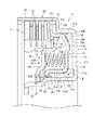
図2は、前記密封装置41の従来の一例を示し、前記動力接続部に設けられた環状のハウジング42の内部に配置されている。図2では、ハウジング42は、環状の密封装置41が挿入されたシリンダ部43と、このシリンダ部43における外周壁43aの軸方向一方側の端部から延びてディスククラッチ44を収納している外側円筒部45とを備えている。
密封装置41は、ハウジング42との間で油圧室46を構成しかつ油圧によりハウジング42内を軸方向一方側へ移動してディスククラッチ44のディスク44aを押圧することによりディスククラッチ44を動力伝達モードとする環状のボンデッドピストンシール47と、このボンデッドピストンシール47に対向させた状態で軸方向一方側に配置された環状のキャンセルプレート48と、ボンデッドピストンシール47及び前記キャンセルプレート48との間に介装され両者を軸方向に離間する方向に付勢するリターンスプリング49と、を備えている。
FIG. 2 shows a conventional example of the
The
ボンデッドピストンシール47は、断面凹型とされて、軽量化のため、薄くされている。ボンデッドピストンシール47は、シリンダ部43の底壁43bに対向している環状部47aと、環状部47aの内周縁からシリンダ部43の内周壁43cに沿って軸方向一方側に延びる内円筒部47bと、環状部47aの外周縁からシリンダ部43の外周壁43aに沿って軸方向一方側に延びる外円筒部47cとを備えている。図2の断面図で示すように、環状部47aと内円筒部47bとの接続部分は、湾曲状に屈曲した断面を有する内側屈曲部47dとされている。又、環状部47aと外円筒部47cとの接続部分は、屈曲した断面を有する外側屈曲部47eとされている。ボンデッドピストンシール47は、各屈曲部47d,47eで、断面形状が変化している。内円筒部47bの先端部には、径方向内方に突出する内向き折曲部47fが形成されている。この内向き折曲部47fは、軸方向に関して、シール部材50の基部50a、及び外円筒部47cが軸方向一方側のストロークエンド(最終押圧位置)に到達した状態でもキャンセルプレート48の内周部と当接しないような大きな隙間51を介して、キャンセルプレート48の内周部と対向している。外円筒部47cの先端部には、径方向外方に突出する外向き折曲部47gが形成されている。
The bonded
ディスククラッチ44による動力伝達時には、油圧室46内に作動油を供給し、ボンデッドピストンシール47を軸方向一方側に移動させて、その外周部の外向き折曲部47gでディスククラッチ44のディスク44aを押圧して、ディスククラッチ44を動力伝達モードとする。この際、ボンデッドピストンシール47には、作動油の油圧により、ボンデッドピストンシール47を外向き折曲部47gを中心として軸方向一方側に押圧するモーメントM1が作用する。
ところで、前記のように、従来では、ボンデッドピストンシール47の内向き折曲部47fとキャンセルプレート48の内周部との間には、軸方向に関して、外円筒部47cが軸方向一方側のストロークエンドに到達した状態でも内向き折曲部47fがキャンセルプレート48の内周部と当接しないような大きな隙間51が形成されているので、ボンデッドピストンシール47の大きな弾性変形が許容されていた。そのため、上記モーメントM1により、軽量化のため厚みが薄くされているボンデッドピストンシール47には、その内周部の内向き折曲部47fがキャンセルプレート48の内周部に向かって軸方向に移動する弾性変形が生じる。又、これと共に、ボンデッドピストンシール47内部には応力が発生するが、ボンデッドピストンシール47における、断面形状の変化部である各屈曲部47d,47eでは、局所的に応力が増大する応力集中が起きる。
When power is transmitted by the
By the way, as described above, conventionally, between the inwardly
しかし、ボンデッドピストンシール47の弾性変形が大きくなると、ボンデッドピストンシール47における、応力集中が起きている各屈曲部47d,47eに生じる応力が増大し、その結果、上記弾性変形の繰り返しにより、各屈曲部47d,47eにクラックが発生し易くなっていた。又、ボンデッドピストンシール47の前記の大きな弾性変形は、外側屈曲部47eを中心(支点)とする内周部側の揺動(移動)による弾性変形を含んでいるので、外側屈曲部47eに生じる応力は大きく、外側屈曲部47eに特にクラックが発生し易くなっていた。そして、前記クラックがボンデッドピストンシール47の破損(疲労破壊)の原因となっていた。
本発明はこのような事情に鑑みてなされたものであり、ピストンシールの破損に繋がる弾性変形を防止することができる密封装置を提供することを目的とする。
However, when the elastic deformation of the
This invention is made | formed in view of such a situation, and it aims at providing the sealing device which can prevent the elastic deformation which leads to the failure | damage of a piston seal.
上記目的を達成するための本発明は、流体圧力により軸方向一方側へ移動してディスククラッチのディスクを押圧することにより、前記ディスククラッチを動力伝達モードとする環状のピストンシールと、このピストンシールに対向させた状態で当該ピストンシールの軸方向一方側に配置された環状のキャンセルプレートとを備える密封装置であって、前記ピストンシールが、径方向に延びる環状部と、この環状部の外周側から軸方向一方側に延びて前記ディスクを押圧する外円筒部と、前記環状部の内周側から軸方向一方側に延びる内円筒部とを有し、前記キャンセルプレートの内周側の側面と前記内円筒部の先端部との間に、前記外円筒部が軸方向一方側のストロークエンドに到達した状態で前記キャンセルプレートの内周側の側面と前記内円筒部の先端部とによって挟み込んで当該内円筒部が軸方向一方側へ移動するのを前記流体圧力に抗して停止させることにより、前記ピストンシールの過度の弾性変形を防止するストッパ部材を備えることを特徴としている。 In order to achieve the above object, the present invention provides an annular piston seal that moves the disk clutch in one axial direction by fluid pressure and presses the disk of the disk clutch to make the disk clutch a power transmission mode, and this piston seal. An annular cancel plate disposed on one side in the axial direction of the piston seal in a state of being opposed to the piston seal, wherein the piston seal includes an annular portion extending in the radial direction and an outer peripheral side of the annular portion An outer cylindrical portion that extends to one side in the axial direction and presses the disk, and an inner cylindrical portion that extends from the inner peripheral side of the annular portion to the one axial side, and a side surface on the inner peripheral side of the cancel plate; Between the tip of the inner cylindrical portion, the outer cylindrical portion reaches the stroke end on one axial side, and the side surface on the inner peripheral side of the cancel plate and the front A stopper member for preventing excessive elastic deformation of the piston seal by stopping the movement of the inner cylindrical portion against one end in the axial direction against the fluid pressure. It is characterized by providing.
この構成によれば、流体圧力により、ピストンシールを軸方向一方側へ移動させ、ピストンシールの外円筒部により、ディスククラッチのディスクを押圧して、ディスククラッチを動力伝達モードとした状態で、ピストンシールの上記移動に伴って、ストッパ部材がキャンセルプレートの内周側の側面と内円筒部の先端部とによって挟み込まれ、これにより、内円筒部の先端部の軸方向一方側への移動が流体圧力に抗して停止させられる。
このように、ストッパ部材により、ピストンシールの内円筒部の先端部の移動が抑制されるので、前記モーメントに起因するピストンシールの破損に繋がる過度の(大きな)弾性変形が防止される。
According to this configuration, the piston seal is moved to one side in the axial direction by the fluid pressure, the disk of the disk clutch is pressed by the outer cylindrical portion of the piston seal, and the disk clutch is set in the power transmission mode. Along with the movement of the seal, the stopper member is sandwiched between the inner peripheral side surface of the cancel plate and the distal end portion of the inner cylindrical portion, so that the movement of the distal end portion of the inner cylindrical portion to one axial side is fluid. Stopped against pressure.
As described above, since the movement of the tip of the inner cylindrical portion of the piston seal is suppressed by the stopper member, excessive (large) elastic deformation that leads to breakage of the piston seal due to the moment is prevented.
尚、前記ストッパが弾性材料により形成されることもある。
この構成によれば、ピストンシールがストッパに当接した際の衝撃は、ストッパの弾性変形により、緩和乃至は吸収され、上記衝撃による異音の発生を抑制できる。
The stopper may be formed of an elastic material.
According to this configuration, the impact when the piston seal comes into contact with the stopper is alleviated or absorbed by the elastic deformation of the stopper, and the generation of abnormal noise due to the impact can be suppressed.
本発明によれば、ピストンシールの破損に繋がる弾性変形を防止することができる密封装置を提供できる。 ADVANTAGE OF THE INVENTION According to this invention, the sealing device which can prevent the elastic deformation which leads to the failure | damage of a piston seal can be provided.
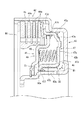
次に、本発明の好ましい実施形態について添付図面を参照しながら説明する。図1は、本発明にかかる密封装置が用いられている自動車用自動変速機の動力断続機構を示す断面図である。
図1中、動力伝達機構1は、遊星ギヤセット(図示せず)に対する動力の伝達を断続するためのディスククラッチCと、このディスククラッチCを作動させるためのクラッチピストンの機能を備えた密封装置10と、これらを内部に収納しているハウジング20とを備えている。
ハウジング20は、例えば、熱間圧延鋼板等を用いて板金プレス成型等によって軸方向一方側に開口する断面凹型に形成された環状の部材であり、内部に環状の密封装置10が挿入、配置されたシリンダ部21と、このシリンダ部21における外周壁21aの軸方向一方側の端部から延びてディスククラッチCを収納している外側円筒部22とを備えている。
Next, preferred embodiments of the present invention will be described with reference to the accompanying drawings. FIG. 1 is a cross-sectional view showing a power interrupting mechanism of an automatic transmission for an automobile in which a sealing device according to the present invention is used.
In FIG. 1, a
The
密封装置10は、シリンダ部21の内部に挿入されかつシリンダ部21との間で第1油室R1を画定している環状のボンデッドピストンシール11と、このボンデッドピストンシール11に対向させた状態で軸方向一方側に配置された環状のキャンセルプレート(バランサー)12と、ボンデッドピストンシール11及びキャンセルプレート12の間に当接介在しているリターンスプリング13とを備えている。
The
ボンデッドピストンシール11は、例えば、機械構造用鋼を用いて熱間型鍛造加工及び切削加工により形成された断面凹型の環状の部材であり、軽量化のため、厚みが薄くされている。ボンデッドピストンシール11は、シリンダ部21の底壁21bに対向して径方向に延びる環状部11aと、環状部11aの内周縁からシリンダ部21の内周壁21cに沿って軸方向一方側に延びる内円筒部11bと、環状部11aの外周縁からシリンダ部21の外周壁21aに沿って軸方向一方側に延びる外円筒部11cとを備えている。図1の断面図で示すように、環状部11aと内円筒部11bとの接続部分は、湾曲状に屈曲した断面を有する内側屈曲部11dとされている。又、環状部11aと外円筒部11cとの接続部分は、屈曲した断面を有する外側屈曲部11eとされている。ボンデッドピストンシール11は、各屈曲部11d,11eで、断面形状が変化している。環状部11aのキャンセルプレート12側の面には、深さが0.5mm程度である3〜6個の凹部11fが周方向等間隔に配設されている。環状部11aの第1油室R1側の面には、凹部11fと対応しかつ0.5mm程度突出する突出部11gが周方向等間隔に配設されている。内円筒部11bの先端部には、径方向内方に突出する内向き折曲部11hが形成されている。
The bonded
ボンデッドピストンシール11には、当該ボンデッドピストンシール11とシリンダ部21との間を密封する環状の第1・第2シール部材14,31が固着されている。第1・第2シール部材14,31は、合成ゴム等の弾性部材から形成されている。第1シール部材14は、環状部11aの外周部及び外側屈曲部11eの第1油室R1側の側面に加硫接着されており、環状部11a等に接着された基部14aと、外側屈曲部11eから外周側へ延びることで外周壁21aの内周面に摺接するシールリップ14bとを有している。第2シール部材31は、内円筒部11bの内周部の第1油室R1側の側面及び内向き折曲部11hに加硫接着されており、内円筒部11b等に接着された基部31aと、内向き折曲部11hの内周部から内周側へ延びることで内周壁21cの外周面に摺接するシールリップ31bを有している。基部31aの軸方向一方側の端部は内向き折曲部11hに外嵌されている。
第1・第2シール部材14,31は、ボンデッドピストンシール11とシリンダ部21との間を密封することで、第1油室R1を密封している。
To the bonded
The first and
シリンダ部21の内周壁21cには、第1油室R1に作動油を供給するための供給口21c1が設けられている。ボンデッドピストンシール11は、この供給口21c1から第1油室R1に供給される作動油の油圧を制御することによって、シリンダ部21内を軸方向に往復移動させることができる。作動油の油圧は、1.4〜2MPaである。
The inner
ボンデッドピストンシール11の外円筒部11cの先端部には、径方向外方に突出しかつディスククラッチCを押圧するための外向き折曲部11iが形成されている。ボンデッドピストンシール11は、作動油の油圧によりシリンダ部21内を軸方向に往復移動することで、外向き折曲部11iの押圧面11jでディスククラッチCを押圧、もしくはその押圧を解除し、当該ディスククラッチCを動力伝達モードと動力伝達切断モードとに切り替える。
An outwardly
キャンセルプレート12は、ボンデッドピストンシール11と同様、機械構造用鋼を用いて型鍛造加工及び切削加工により形成された環状の部材であり、ボンデッドピストンシール11及びハウジング20との間で第2油室R2を画定している。キャンセルプレート12は、ボンデッドピストンシール11の内周側に位置する大径環状部12aと、大径環状部12aよりも軸方向一端側に位置する中間環状部12bと、これらを軸方向に繋ぐ円筒部12cと、中間環状部12bよりも軸方向一端側に位置する小径環状部12dと、中間環状部12bと小径環状部12dとを軸方向に繋ぐ環状の連結部12eとを備えている。
Similar to the bonded
小径環状部12dは、その内周端がハウジング20の内側円筒部23に外嵌されており、さらに、内側円筒部23に固定されたストッパ15によって、軸方向一方側への移動が規制されている。
大径環状部12aの外周端部には、キャンセルプレート12と、ボンデッドピストンシール11との間を密封する環状の第3シール部材16が固着されている。第3シール部材16は、合成ゴム等の弾性部材を用いて大径環状部12aの外周端部に加硫接着されており、外周側へ延びることでボンデッドピストンシール11の外円筒部11cの内周面に摺接するシールリップ16aを有している。
第3シール部材16は、キャンセルプレート12とボンデッドピストンシール11との間を密封することで、第2油室R2を密封している。
The inner peripheral end of the small-diameter
An annular
The
キャンセルプレート12の小径環状部12dの外周部と連結部12eの第2油室R2側の面には、金属製の環状ストッパ部材32が固着されている。ストッパ部材32は、ディスククラッチCの動力伝達切断モード時に、軸方向に関して、隙間33を介して、ボンデッドピストンシール11の内向き折曲部11hと対向すると共に、ディスククラッチCの動力伝達モード時に、内向き折曲部11hと当接する。隙間33の大きさは、0.3〜0.5mm程度とされている。尚、ストッパ部材32は環状でなくてもよく、キャンセルプレート12の内周部に周方向等間隔(等間隔でなくてもよい)に複数配設してもよい。
A metal
リターンスプリング13は、ボンデッドピストンシール11の環状部11aとキャンセルプレート12の中間環状部12bとに当接することで、ボンデッドピストンシール11及びキャンセルプレート12の間に介在しており、両者を軸方向に離間する方向に付勢している。リターンスプリング13は、ボンデッドピストンシール11が軸方向一方側へ移動してディスククラッチCを押圧している状態から押圧を解除する際に、その付勢力によって、ボンデッドピストンシール11を軸方向他方側へ速やかに移動させる。
The
ディスククラッチCは、多数のディスクC1を重ね合わせて構成されており、ボンデッドピストンシール11によって押圧されることで、これらディスクC1が圧着されて、ディスククラッチCが動力伝達モードとなり、前記遊星ギヤセットに対して動力を伝達する。一方、押圧が解除されると、ディスククラッチCが動力伝達切断モードとなり、動力伝達を切断する。すなわち、密封装置10は、ボンデッドピストンシール11の軸方向への往復移動によって、ディスククラッチCを作動させ当該ディスククラッチCによる動力の伝達を断続することができ、動力伝達機構1におけるクラッチピストンとしての機能を有している。
The disk clutch C is configured by superimposing a large number of disks C1. When the disk clutch C is pressed by the bonded
上記構成例によれば、ディスククラッチCの動力伝達切断モード時には、図1に示すように、ボンデッドピストンシール11の内向き折曲部11hは、軸方向に関して、第2シール部材31の基部31a及び隙間33を介して、キャンセルプレート12の内周部に備えられたストッパ部材32と対向している。
ディスククラッチCにより、動力伝達を行う際には、第1油室R1に作動油を供給し、ボンデッドピストンシール11を軸方向一方側へ移動させて、その外周部の外向き折曲部11iによりディスククラッチCのディスクC1を押圧して、ディスククラッチCを動力伝達モードとする。
According to the above configuration example, when the disc clutch C is in the power transmission cut mode, as shown in FIG. 1, the inwardly
When power is transmitted by the disk clutch C, hydraulic oil is supplied to the first oil chamber R1, the bonded
この際、ボンデッドピストンシール11の軸方向一方側への移動に伴って、ボンデッドピストンシール11の内向き折曲部11hがストッパ部材32と当接し、内向き折曲部11hの軸方向一方側への移動が、作動油の油圧に抗して停止させられる。
この停止より前に、ボンデッドピストンシール11の外向き折曲部11iが、そのディスククラッチCの押圧ストロークで、ストロークエンド(最終押圧位置)に到達するようであれば、この到達から上記停止までの間に、ボンデッドピストンシール11には、作動油の油圧により、ボンデッドピストンシール11を外向き折曲部11iを中心として軸方向一方側に押圧するモーメントMが作用する。
At this time, as the bonded
If the outward
これにより、軽量化のため厚みが薄くされているボンデッドピストンシール11には、その内周部の内向き折曲部11hがキャンセルプレート12の内周部に向かって軸方向に移動する弾性変形が生じる。又、これと共に、ボンデッドピストンシール11内部には応力が発生するが、ボンデッドピストンシール11における、断面形状の変化部である各屈曲部11d,11eでは、局所的に応力が増大する応力集中が起きる。
Accordingly, the bonded
この場合において、本例では、上記のように、ストッパ部材32により、ボンデッドピストンシール11の内向き折曲部11hの移動が停止されるので、ボンデッドピストンシール11の過度の(大きな)弾性変形が防止される。
その結果、ボンデッドピストンシール11における、応力集中が起きている各屈曲部11d,11eに生じる応力が従来のように増大せず、これにより、上記弾性変形の繰り返しによって屈曲部11d,11eにクラックが発生することを抑制できて、ボンデッドピストンシール11の破損(疲労破壊)を防止できる。
In this case, in this example, since the movement of the inwardly
As a result, the stress generated in each of the
なお、上記実施の形態では、ストッパ部材32を金属製としたが、合成ゴム等の弾性部材から形成することもある。この場合、ストッパ部材32の厚みは、外向き折曲部11iのストロークエンドでストッパ部材32が軸方向一方側に弾性収縮した状態で内向き折曲部11hの移動を停止させる厚みに設定される。このようにすれば、ボンデッドピストンシール11がストッパ部材32に当接した際の衝撃は、ストッパ部材32の弾性変形により、緩和乃至は吸収され、上記衝撃による異音の発生を抑制できる。ストッパ部材32の構成材料として、ゴムを使用する場合には、例えば、ゴム硬度80A以上の硬いゴムが使用される。
In the above embodiment, the
上記の場合のストッパ部材32のキャンセルプレート12への固着方法としては、(1)ストッパ部材32をキャンセルプレート12に加硫接着する方法、(2)キャンセルプレート12及びストッパ部材32の一方に、他方側に突出する凸部を形成し、他方に、対応する凹部を形成して、ストッパ部材32を弾性変形させながら、前記凸部を前記凹部に嵌め込む(嵌合する)方法等がある。前記凸部及び前記凹部は、全周にわたって形成される場合と、周方向等間隔(等間隔でなくてもよい。)に複数形成される場合とがある。キャンセルプレート12に前記凸部又は前記凹部を形成する場合には、プレス及び打ち出し(叩き出し)等により、形成する。
The fixing method of the
なお、前記の実施の形態においては、ストッパ部材をキャンセルプレートに備えたが、ストッパ部材をボンデッドピストンシールやそれ以外の部材に備えてもよい。又、前記の実施の形態においては、本発明を密封装置が用いられている自動車用自動変速機の動力断続機構に適用した例について記載した。しかし、本発明はそのような構成に限定されない。 In the above-described embodiment, the stopper member is provided in the cancel plate. However, the stopper member may be provided in a bonded piston seal or other members. In the above-described embodiment, an example in which the present invention is applied to a power interrupt mechanism of an automatic transmission for an automobile in which a sealing device is used has been described. However, the present invention is not limited to such a configuration.
その他、別紙の特許請求の範囲内での種々の設計変更及び修正を加え得ることは勿論である。すなわち、本明細書で開示した実施の形態は単に例示であって、本発明が前述した実施の形態のみに限定されるわけではない。本発明の範囲は、本明細書の記載内容を参酌した上で、別紙の特許請求の範囲によって示され、そこに記載された文言と均等の意味及び範囲内での全ての変更を含む。 It goes without saying that various design changes and modifications can be made within the scope of the appended claims. That is, the embodiment disclosed in this specification is merely an example, and the present invention is not limited to the embodiment described above. The scope of the present invention is indicated by the appended claims after taking into account the description of the present specification, and includes all modifications within the meaning and scope equivalent to the words described therein.
10:密封装置、11:ボンデッドピストンシール、11a:環状部、11b:内円筒部、11c:外円筒部、12:キャンセルプレート、20:ハウジング、32:ストッパ部材、33:隙間、C:ディスククラッチ、C1:ディスク 10: sealing device, 11: bonded piston seal, 11a: annular portion, 11b: inner cylindrical portion, 11c: outer cylindrical portion, 12: cancel plate, 20: housing, 32: stopper member, 33: gap, C: disc Clutch, C1: disc
Claims (2)
前記ピストンシールが、径方向に延びる環状部と、この環状部の外周側から軸方向一方側に延びて前記ディスクを押圧する外円筒部と、前記環状部の内周側から軸方向一方側に延びる内円筒部とを有し、
前記キャンセルプレートの内周側の側面と前記内円筒部の先端部との間に、前記外円筒部が軸方向一方側のストロークエンドに到達した状態で前記キャンセルプレートの内周側の側面と前記内円筒部の先端部とによって挟み込んで当該内円筒部が軸方向一方側へ移動するのを前記流体圧力に抗して停止させることにより、前記ピストンシールの過度の弾性変形を防止するストッパ部材を備えることを特徴とする密封装置。 An annular piston seal that makes the disk clutch a power transmission mode by moving to one side in the axial direction by fluid pressure and pressing the disk of the disk clutch, and a shaft of the piston seal in a state of being opposed to the piston seal A sealing device comprising an annular cancel plate arranged on one side of the direction,
The piston seal includes an annular portion extending in the radial direction, an outer cylindrical portion that extends from the outer peripheral side of the annular portion to the one axial side, and presses the disk, and from the inner peripheral side of the annular portion to the one axial side. An inner cylindrical portion extending,
Between the side surface on the inner peripheral side of the cancel plate and the tip end portion of the inner cylindrical portion, the side surface on the inner peripheral side of the cancel plate and the outer cylindrical portion reach the stroke end on one axial side. A stopper member for preventing excessive elastic deformation of the piston seal by stopping the movement of the inner cylindrical portion against one end in the axial direction against the fluid pressure. A sealing device comprising:
The sealing device according to claim 1, wherein the stopper is made of an elastic material.
Priority Applications (1)
| Application Number | Priority Date | Filing Date | Title |
|---|---|---|---|
| JP2013241572A JP6279293B2 (en) | 2013-11-22 | 2013-11-22 | Sealing device |
Applications Claiming Priority (1)
| Application Number | Priority Date | Filing Date | Title |
|---|---|---|---|
| JP2013241572A JP6279293B2 (en) | 2013-11-22 | 2013-11-22 | Sealing device |
Publications (2)
| Publication Number | Publication Date |
|---|---|
| JP2015102116A true JP2015102116A (en) | 2015-06-04 |
| JP6279293B2 JP6279293B2 (en) | 2018-02-14 |
Family
ID=53377995
Family Applications (1)
| Application Number | Title | Priority Date | Filing Date |
|---|---|---|---|
| JP2013241572A Active JP6279293B2 (en) | 2013-11-22 | 2013-11-22 | Sealing device |
Country Status (1)
| Country | Link |
|---|---|
| JP (1) | JP6279293B2 (en) |
Cited By (1)
| Publication number | Priority date | Publication date | Assignee | Title |
|---|---|---|---|---|
| CN115443386A (en) * | 2020-05-01 | 2022-12-06 | Nok株式会社 | Structure for identifying constituent element of clutch piston mechanism and method for identifying constituent element of clutch piston mechanism |
Citations (4)
| Publication number | Priority date | Publication date | Assignee | Title |
|---|---|---|---|---|
| JPH09303423A (en) * | 1996-05-09 | 1997-11-25 | Nok Corp | Sealing device |
| JP2007024167A (en) * | 2005-07-15 | 2007-02-01 | Mazda Motor Corp | Clutch structure of transmission |
| JP2008256057A (en) * | 2007-04-04 | 2008-10-23 | Nok Corp | Piston for automatic transmission |
| JP2010270833A (en) * | 2009-05-21 | 2010-12-02 | Koyo Sealing Techno Co Ltd | Sealing device |
-
2013
- 2013-11-22 JP JP2013241572A patent/JP6279293B2/en active Active
Patent Citations (4)
| Publication number | Priority date | Publication date | Assignee | Title |
|---|---|---|---|---|
| JPH09303423A (en) * | 1996-05-09 | 1997-11-25 | Nok Corp | Sealing device |
| JP2007024167A (en) * | 2005-07-15 | 2007-02-01 | Mazda Motor Corp | Clutch structure of transmission |
| JP2008256057A (en) * | 2007-04-04 | 2008-10-23 | Nok Corp | Piston for automatic transmission |
| JP2010270833A (en) * | 2009-05-21 | 2010-12-02 | Koyo Sealing Techno Co Ltd | Sealing device |
Cited By (1)
| Publication number | Priority date | Publication date | Assignee | Title |
|---|---|---|---|---|
| CN115443386A (en) * | 2020-05-01 | 2022-12-06 | Nok株式会社 | Structure for identifying constituent element of clutch piston mechanism and method for identifying constituent element of clutch piston mechanism |
Also Published As
| Publication number | Publication date |
|---|---|
| JP6279293B2 (en) | 2018-02-14 |
Similar Documents
| Publication | Publication Date | Title |
|---|---|---|
| JP6117000B2 (en) | Piston integrated seal | |
| JP7141208B2 (en) | sealing device | |
| JP6279293B2 (en) | Sealing device | |
| JP6193074B2 (en) | Clutch piston and manufacturing method thereof | |
| JP2011163438A (en) | Sealing ring for reciprocating motion | |
| JP4843405B2 (en) | Sealing device | |
| JP6576745B2 (en) | SEALING DEVICE AND CANCEL PLATE MANUFACTURING METHOD USED FOR THE SAME | |
| EP2405153A2 (en) | Clutch release bearing device | |
| JP5394131B2 (en) | Manufacturing method of sealing device | |
| JP2010190391A (en) | Piston seal for automatic transmission | |
| US20070295576A1 (en) | Clutch Piston | |
| JP2007303493A (en) | Sealing device | |
| JP2023003650A (en) | sealing device | |
| JP2005265073A (en) | Piston device | |
| JP4972515B2 (en) | Clutch piston for fluid transmission | |
| JP2011017376A (en) | Seal structure for fluid machine | |
| JP2007225046A (en) | Seal integrated piston | |
| JP2008256057A (en) | Piston for automatic transmission | |
| WO2020230466A1 (en) | Hydraulic actuator sealing device | |
| JP2006144901A (en) | Reciprocation seal | |
| JP7458240B2 (en) | sealing device | |
| JP2008256056A (en) | Piston for automatic transmission | |
| JP2005325995A (en) | Piston | |
| JP2009058053A (en) | Piston for automatic transmission | |
| JP2008020030A (en) | Automatic transmission piston |
Legal Events
| Date | Code | Title | Description |
|---|---|---|---|
| A621 | Written request for application examination |
Free format text: JAPANESE INTERMEDIATE CODE: A621 Effective date: 20160815 |
|
| A977 | Report on retrieval |
Free format text: JAPANESE INTERMEDIATE CODE: A971007 Effective date: 20170412 |
|
| A131 | Notification of reasons for refusal |
Free format text: JAPANESE INTERMEDIATE CODE: A131 Effective date: 20170530 |
|
| A521 | Request for written amendment filed |
Free format text: JAPANESE INTERMEDIATE CODE: A523 Effective date: 20170713 |
|
| TRDD | Decision of grant or rejection written | ||
| A01 | Written decision to grant a patent or to grant a registration (utility model) |
Free format text: JAPANESE INTERMEDIATE CODE: A01 Effective date: 20180109 |
|
| A61 | First payment of annual fees (during grant procedure) |
Free format text: JAPANESE INTERMEDIATE CODE: A61 Effective date: 20180117 |
|
| R150 | Certificate of patent or registration of utility model |
Ref document number: 6279293 Country of ref document: JP Free format text: JAPANESE INTERMEDIATE CODE: R150 |
|
| R250 | Receipt of annual fees |
Free format text: JAPANESE INTERMEDIATE CODE: R250 |
|
| R250 | Receipt of annual fees |
Free format text: JAPANESE INTERMEDIATE CODE: R250 |