JP2015085701A5 - - Google Patents
Download PDFInfo
- Publication number
- JP2015085701A5 JP2015085701A5 JP2013222981A JP2013222981A JP2015085701A5 JP 2015085701 A5 JP2015085701 A5 JP 2015085701A5 JP 2013222981 A JP2013222981 A JP 2013222981A JP 2013222981 A JP2013222981 A JP 2013222981A JP 2015085701 A5 JP2015085701 A5 JP 2015085701A5
- Authority
- JP
- Japan
- Prior art keywords
- gear
- steering
- detection
- rotation
- angle
- Prior art date
- Legal status (The legal status is an assumption and is not a legal conclusion. Google has not performed a legal analysis and makes no representation as to the accuracy of the status listed.)
- Granted
Links
- 238000001514 detection method Methods 0.000 claims description 51
- 239000003638 reducing agent Substances 0.000 claims description 16
- 239000000758 substrate Substances 0.000 claims description 13
- 239000004519 grease Substances 0.000 claims description 9
- 239000011347 resin Substances 0.000 claims description 2
- 229920005989 resin Polymers 0.000 claims description 2
- 238000005096 rolling process Methods 0.000 claims description 2
- 239000000314 lubricant Substances 0.000 description 8
- 238000005192 partition Methods 0.000 description 3
- 230000005540 biological transmission Effects 0.000 description 2
- 238000000034 method Methods 0.000 description 2
- 210000001503 Joints Anatomy 0.000 description 1
- 230000000875 corresponding Effects 0.000 description 1
- 238000005516 engineering process Methods 0.000 description 1
- 230000004907 flux Effects 0.000 description 1
- 238000005461 lubrication Methods 0.000 description 1
- 230000002093 peripheral Effects 0.000 description 1
Images
Description
従来の電動パワーステアリング装置では、ステアリングホイールに印加された操舵トルクに応じて電動モータから補助操舵トルクを発生し、これを動力伝達機構(ウォーム減速機)により減速して操舵機構の出力軸に伝達している。ここで、電動パワーステアリング装置の構成を、図1を基に説明する。電動パワーステアリング装置は、所定軸周りに回転するステアリングシャフト2の回転角度を取得するアングルセンサユニット30を備えている。ステアリングシャフト2は、ウォーム減速機11、ユニバーサルジョイント4・6、ラックアンドピニオン機構6を介してタイロッド9に連結されている。ステアリングシャフト2には、ステアリングホイール1に印加された操舵トルクTを検出するトルクセンサユニット14が設けられており、操舵トルクTによって図示しないトーションバーが捩れると、トルクセンサユニット14は操舵トルクTに応じた電気信号を出力する。ステアリングシャフト2には、操舵トルクTを補助する電動モータ12がウォーム減速機11を介して連結されている。アングルセンサユニット30及びトルクセンサユニット14から出力された各信号は、図2に示すEPSコントロールユニット15に伝達され、前記各信号に基づき、EPSコントロールユニット15は電動モータ12の制御を行う。
このような電動パワーステアリング装置に搭載するアングルセンサユニット30として、例えば特許文献1に記載の技術が知られている。この技術は、ステアリングシャフトと一体に回転する環状駆動ギヤとマグネットが固定された従動ギヤが噛合し、従動ギヤに固定されたマグネットの磁束方向を磁気変化検出素子(センサ)で検知して、ステアリングシャフト2の回転角を検出するものである。このとき、従動ギヤはユニットハウジングの従動ギヤ収容孔に納められ、磁気変化検出素子が実装された基板が近接して配置される。
In the conventional electric power steering device, auxiliary steering torque is generated from the electric motor in accordance with the steering torque applied to the steering wheel, and this is decelerated by the power transmission mechanism (worm reducer) and transmitted to the output shaft of the steering mechanism. doing. Here, the configuration of the electric power steering apparatus will be described with reference to FIG. The electric power steering equipment is provided with an angle sensor unit 30 to obtain the rotational angle of the steering shaft 2 that rotates around a predetermined axis. The steering shaft 2 is connected to a tie rod 9 via a worm speed reducer 11 , universal joints 4 and 6 , and a rack and pinion mechanism 6. The steering shaft 2, the torque sensor unit 14 for detecting the steering torque T applied to the steering wheel 1 is provided, the twists the torsion bar (not shown) by the steering torque T, the torque sensor unit 14 is a steering torque An electric signal corresponding to T is output. An electric motor 12 that assists the steering torque T is connected to the steering shaft 2 via a worm reducer 11 . Signals output from the angle sensor unit 30 and the torque sensor unit 14 are transmitted to the EPS control unit 15 shown in FIG. 2, and the EPS control unit 15 controls the electric motor 12 based on the signals.
As an angle sensor unit 30 mounted on such an electric power steering device, for example, a technique described in Patent Document 1 is known. In this technology, an annular drive gear that rotates integrally with a steering shaft meshes with a driven gear to which a magnet is fixed, and a magnetic change detecting element (sensor) detects the magnetic flux direction of the magnet fixed to the driven gear, thereby steering. The rotation angle of the shaft 2 is detected. At this time, the driven gear is housed in the driven gear receiving hole of the unit housing, and the substrate on which the magnetic change detecting element is mounted is disposed close to the driven gear.
ここで、ステアリングシャフトの舵角情報は、操舵系の下流(タイヤに近い側)でセンシングするのが理想であり、例えば図1において、図示しないトーションバーによる捩れの影響を受けない、ウォーム減速機11から下流側にアングルセンサユニット30を配置することが望ましい。さらに、近年、電動パワーステアリング装置のコンパクト化が求められており、構成部品や配線を少なくするために、アングルセンサユニット30及びトルクセンサユニット14と、電動モータ12及びウォーム減速機11、EPSコントロールユニット15とを、近接させて配置する必要がある。特に、ウォーム減速機11のステアリングシャフト側の歯車にアングルセンサユニット30を近接させることが考えられる。
しかしながら、ウォーム減速機11を納めるハウジング内には潤滑の為にグリース等の潤滑剤が封入されており、ウォーム減速機11のハウジング内に特許文献1に記載の技術からなる舵角センサを配置した場合、潤滑剤や、潤滑剤から離油した油分が飛散し、舵角センサの磁気変化検出素子に接触して磁気変化検出素子の動作不良を誘引する虞がある。
Here, the steering angle information of the steering shaft is ideally sensed downstream of the steering system (on the side closer to the tire). For example, in FIG. 1, a worm speed reducer that is not affected by torsion by a torsion bar ( not shown) . It is desirable to dispose the angle sensor unit 30 downstream from 11 . Furthermore, in recent years, there has been a demand for downsizing of the electric power steering apparatus. In order to reduce the number of components and wiring, the angle sensor unit 30 and the torque sensor unit 14 , the electric motor 12, the worm reducer 11 , and the EPS control unit. 15 need to be placed close to each other. In particular, it is conceivable to bring the angle sensor unit 30 close to the gear on the steering shaft side of the worm reducer 11 .
However, in the housing to pay worm reduction gear 11 are lubricant sealed such as grease for lubrication was arranged steering angle sensor comprising a technique described in Patent Document 1 in the housing of the worm reduction gear 11 In this case, there is a possibility that the lubricant or the oil separated from the lubricant scatters and contacts the magnetic change detection element of the rudder angle sensor to induce a malfunction of the magnetic change detection element.
そこで、本発明は、ステアリングシャフトの回転角を伝達する歯車に近接したセンサ素子や基板にグリース等の潤滑剤及び潤滑剤の油分が飛散するのを防止した舵角検出部を備える電動パワーステアリング装置を提供することを課題としている。 Accordingly, the present invention provides an electric power steering apparatus including a steering angle detection unit that prevents a lubricant such as grease and oil components of the lubricant from being scattered on a sensor element and a substrate close to a gear that transmits a rotation angle of a steering shaft. It is an issue to provide.
上記課題を解決する為に、本発明に係る電動パワーステアリング装置の一態様は、ステアリングホイールから伝達される操舵トルクを検出するトルク検出部と、前記トルク検出部で検出した操舵トルクに応じた操舵補助トルクを発生する電動モータと、前記電動モータが発生した操舵補助トルクを減速して車両のステアリング機構の出力軸に伝達するウォーム減速機と、前記ウォーム減速機を収容するギヤボックスハウジングに組付可能に構成され、操舵軸の回転角を検出する舵角検出部と、を備え、前記ウォーム減速機を構成するウォームホイールの軸方向端面にフェースギヤが形成されており、前記舵角検出部は、前記フェースギヤと噛み合う中間歯車と、径方向に着磁された磁石が固着され、前記中間歯車と噛み合う回転検出用歯車と、前記中間歯車及び前記回転検出用歯車を回転可能に支持する歯車支持部と、前記回転検出用歯車の磁石と対向する位置に磁気検出素子を配置した角度検出用基板と、少なくとも前記中間歯車、前記回転検出用歯車及び前記歯車支持部を収容すると共に、これらを収容した状態で前記中間歯車の一部が露出する開口部を有するセンサハウジングと、を備え、前記センサハウジングは、前記回転検出用歯車の収容空間と、前記角度検出用基板の収容空間との間を空間的に隔離していることを特徴とする。
また、この発明の電動パワーステアリングにおいて、前記センサハウジングは、樹脂で形成されていることが好ましい。
また、上記電動パワーステアリング装置において、前記フェースギヤおよび、前記中間歯車、前記回転検出用歯車の各歯面がグリース潤滑されていることが好ましい。
また、上記電動パワーステアリング装置において、前記回転検出用歯車に使用されるグリースは、前記ウォーム減速機に使用されるグリースと同じものであることが好ましい。
In order to solve the above-described problem, an aspect of the electric power steering apparatus according to the present invention includes a torque detection unit that detects a steering torque transmitted from a steering wheel, and steering in accordance with the steering torque detected by the torque detection unit. An electric motor that generates auxiliary torque, a worm reducer that decelerates and transmits the steering auxiliary torque generated by the electric motor to the output shaft of the steering mechanism of the vehicle, and a gear box housing that houses the worm reducer A steering angle detector configured to detect a rotation angle of the steering shaft, and a face gear is formed on an axial end surface of the worm wheel that constitutes the worm speed reducer. an intermediate gear meshing with the face gear, is fixed is magnetized magnets in a radial direction and the intermediate gear and intermesh bypass rolling detection gear Wherein the intermediate gear及beauty before Symbol rotation detection gear supporting portion for rotatably supporting the gears, an angle detection substrate disposing the magnetic sensing element magnet and pair direction position of the rotation detection gear, at least the An intermediate gear, a rotation detecting gear, and a gear support, and a sensor housing having an opening through which a part of the intermediate gear is exposed in a state in which the intermediate gear is accommodated. The space for accommodating the rotation detecting gear and the space for accommodating the angle detecting substrate are spatially separated from each other.
In the electric power steering according to the present invention, it is preferable that the sensor housing is made of resin.
In the electric power steering apparatus, it is preferable that the tooth gears of the face gear, the intermediate gear, and the rotation detecting gear are grease-lubricated.
In the electric power steering apparatus, the grease used for the rotation detecting gear is preferably the same as the grease used for the worm reducer.
このように、回転検出用歯車の収容空間と、角度検出用基板の収容部との間に隔壁を設けることで、回転検出用歯車等に塗布されたグリース等の潤滑剤及び、潤滑剤から離油した油分が飛散しても磁気検出素子や角度検出用基板に付着するのを防止することができる。 In this way, by providing a partition wall between the rotation detection gear housing space and the angle detection board housing portion, lubricant such as grease applied to the rotation detection gear and the lubricant can be separated from the lubricant. Even if the oiled oil is scattered, it can be prevented from adhering to the magnetic detection element and the angle detection substrate.
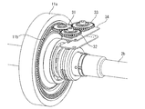
また、アングルセンサユニット30の搭載位置は、このウォームホイール11aに設けられたフェースギヤ11bのピッチ円周上であれば、任意に設定可能である。但し、周辺部品との関係や、配線取回し等を考慮してレイアウトすることが望ましい。
アングルセンサユニット30は、図3に示すように、中間歯車31、第一検出用歯車(第一の回転検出用歯車)32、第二検出用歯車(第二の回転検出用歯車)33、及び角度検出用基板34を少なくとも備える。中間歯車31は、角度検出機能を有しない回転伝達用歯車であり、フェースギヤ11bに噛合している。この中間歯車31には、第一検出用歯車32と第二検出用歯車33とが噛合している。これにより、操舵軸(出力軸2b)の回転が中間歯車31を介して検出用歯車32及び33に伝達される。
アングルセンサユニット30の、中間歯車31、第一検出用歯車32、第二検出用歯車の歯面にはグリースが塗布され、潤滑される。中間歯車31は直接フェースギヤ11bと直接噛合しており、ウォーム減速機11側のグリースがアングルセンサユニット30側に飛散、流動するため、使用するグリースはウォーム減速機11で使用されるグリースと同じものを使用することが好ましい。
The mounting position of the angle sensor unit 30 can be arbitrarily set as long as it is on the pitch circumference of the
As shown in FIG. 3, the angle sensor unit 30 includes an
Grease is applied to the tooth surfaces of the
図4は、アングルセンサユニット30の具体的構成を示す分解斜視図である。
アングルセンサユニット30は、中間歯車31、第一検出用歯車32、第二検出用歯車33、角度検出用基板34、アングルセンサハウジング38、及びアングルセンサカバー39を備える。
アングルセンサハウジング38には、歯車支持部38aと信号コネクタ38bとが一体成型されており、ここに中間歯車31及び検出用歯車32,33が組み込まれる。また、アングルセンサハウジング38の裏側(歯車支持部38aが成型された面とは反対側)には、角度検出用基板34が組み込まれる。このとき、中間歯車31と検出用歯車32,33とを、歯車支持部38aによって支持し、角度検出用基板34を信号コネクタ38bに接続する。そして、アングルセンサハウジング38に、中間歯車31及び検出用歯車32,33を配置した側からアングルセンサカバー39を取り付けることで、アングルセンサユニット30を構成する。
FIG. 4 is an exploded perspective view showing a specific configuration of the angle sensor unit 30.
The angle sensor unit 30 includes an
A gear support portion 38a and a signal connector 38b are integrally formed in the angle sensor housing 38, and an
検出用歯車32,33と、歯車支持部38a,38aとの係合部は、図5に示すような構成となっている。検出用歯車32,33の歯車支持部38a,38aとの係合部には、検出用歯車32,33にそれぞれに埋設された磁石32a,33aの周囲を取り囲む様に円環状の突起32b,33bが設けられている。この突起32b,33bにより検出用歯車32,33は、歯車支持部38a,38aと係合し、アングルセンサハウジング38に対して回転可能に支持される。
And the
歯車支持部38a,38aの内側は隔壁38c,38cによって、検出用歯車32,33及び磁石32a,33aと、角度検出用基板34上と磁気検出素子との間を所定の間隔で近接可能に隔離している。また、アングルセンサハウジング38は、検出用歯車32,33と、角度検出用基板34との間に貫通穴を形成せず、空間的に隔離する構造となっている。
Gear support portions 38a, 38a of the inner partition wall 38c, by 38c, the
SM…ステアリング機構
1…ステアリングホイール
2…ステアリングシャフト
3…ステアリングコラム
4,6…ユニバーサルジョイント
5…中間シャフト
8…ステアリングギヤ
10…操舵補助機構
11…ウォーム減速機
11a…ウォームホイール
11b…フェースギヤ
12…電動モータ
13…ギヤボックスハウジング
13a…ギヤボックスカバー
14…トルクセンサユニット
15…EPSコントロールユニット(ECU)
30…アングルセンサユニット
31…中間歯車
32…第一検出用歯車(第一の回転検出用歯車)
32a…磁石
32b…突起
33…第二検出用歯車(第二の回転検出用歯車)
33a…磁石
33b…突起
34…角度検出用基板
38…アングルセンサハウジング
38a…歯車支持部
38c…隔壁
39…アングルセンサカバー
SM ... steering mechanism 1 ... steering wheel 2 ... steering shaft 3 ... steering column 4, 6 ... universal joint 5 ... intermediate shaft 8 ... steering gear 10 ... steering assist mechanism 11 ...
30 ...
32a ... magnet
33a ... magnets
Claims (4)
前記トルク検出部で検出した操舵トルクに応じた操舵補助トルクを発生する電動モータと、
前記電動モータが発生した操舵補助トルクを減速して車両のステアリング機構の出力軸に伝達するウォーム減速機と、
前記ウォーム減速機を収容するギヤボックスハウジングに組付可能に構成され、操舵軸の回転角を検出する舵角検出部と、を備え、
前記ウォーム減速機を構成するウォームホイールの軸方向端面にフェースギヤが形成されており、
前記舵角検出部は、前記フェースギヤと噛み合う中間歯車と、径方向に着磁された磁石が固着され、前記中間歯車と噛み合う回転検出用歯車と、前記中間歯車及び前記回転検出用歯車を回転可能に支持する歯車支持部と、前記回転検出用歯車の磁石と対向する位置に磁気検出素子を配置した角度検出用基板と、少なくとも前記中間歯車、前記回転検出用歯車及び前記歯車支持部を収容すると共に、これらを収容した状態で前記中間歯車の一部が露出する開口部を有するセンサハウジングと、を備え、
前記センサハウジングは、前記回転検出用歯車の収容空間と、前記角度検出用基板の収容空間との間を隔離していることを特徴とする電動パワーステアリング装置。 A torque detector for detecting a steering torque transmitted from the steering wheel;
An electric motor that generates a steering assist torque according to the steering torque detected by the torque detector;
A worm reducer that decelerates the steering assist torque generated by the electric motor and transmits it to the output shaft of the steering mechanism of the vehicle;
A steering angle detector configured to be assembled to a gear box housing that houses the worm reducer, and detecting a rotation angle of a steering shaft;
A face gear is formed on the axial end surface of the worm wheel constituting the worm reducer,
The steering angle detecting section, and an intermediate gear that meshes with the face gear, magnetized magnet is fixed in the radial direction, and if bypass rolling detection gear meshing with the intermediate gear, the intermediate gear及beauty before Symbol Rotation a gear supporting portion for rotatably supporting the detection gear, the the angle detection substrate disposing the magnetic sensing element magnet and pair toward the position of the rotation detection gear, at least the intermediate gear, the rotation detection gear And a sensor housing having an opening through which a part of the intermediate gear is exposed in a state in which the gear support is accommodated and the gear support is accommodated.
The electric power steering apparatus according to claim 1, wherein the sensor housing separates a space for accommodating the rotation detecting gear and a space for accommodating the angle detecting substrate.
Priority Applications (1)
| Application Number | Priority Date | Filing Date | Title |
|---|---|---|---|
| JP2013222981A JP6183151B2 (en) | 2013-10-28 | 2013-10-28 | Electric power steering device |
Applications Claiming Priority (1)
| Application Number | Priority Date | Filing Date | Title |
|---|---|---|---|
| JP2013222981A JP6183151B2 (en) | 2013-10-28 | 2013-10-28 | Electric power steering device |
Publications (3)
| Publication Number | Publication Date |
|---|---|
| JP2015085701A JP2015085701A (en) | 2015-05-07 |
| JP2015085701A5 true JP2015085701A5 (en) | 2016-11-10 |
| JP6183151B2 JP6183151B2 (en) | 2017-08-23 |
Family
ID=53048987
Family Applications (1)
| Application Number | Title | Priority Date | Filing Date |
|---|---|---|---|
| JP2013222981A Expired - Fee Related JP6183151B2 (en) | 2013-10-28 | 2013-10-28 | Electric power steering device |
Country Status (1)
| Country | Link |
|---|---|
| JP (1) | JP6183151B2 (en) |
Families Citing this family (1)
| Publication number | Priority date | Publication date | Assignee | Title |
|---|---|---|---|---|
| CN109781834B (en) * | 2019-03-07 | 2022-08-02 | 宁波市劳动安全技术服务公司 | Storage tank bottom plate corrodes magnetic leakage detection device |
Family Cites Families (6)
| Publication number | Priority date | Publication date | Assignee | Title |
|---|---|---|---|---|
| JPS57163869A (en) * | 1982-03-03 | 1982-10-08 | Canon Inc | Motorcar |
| JP4200425B2 (en) * | 2002-10-23 | 2008-12-24 | 株式会社ジェイテクト | Reducer and electric power steering apparatus including the same |
| JP4093022B2 (en) * | 2002-11-14 | 2008-05-28 | 日本精工株式会社 | Electric power steering device |
| JP2008308119A (en) * | 2007-06-18 | 2008-12-25 | Jtekt Corp | Electric power steering device |
| JP2010271180A (en) * | 2009-05-21 | 2010-12-02 | Alps Electric Co Ltd | Multiple rotation angle detector |
| JP6164037B2 (en) * | 2013-10-15 | 2017-07-19 | 日本精工株式会社 | Electric power steering device |
-
2013
- 2013-10-28 JP JP2013222981A patent/JP6183151B2/en not_active Expired - Fee Related
Similar Documents
| Publication | Publication Date | Title |
|---|---|---|
| EP2664906B1 (en) | Torque angle sensor | |
| KR101128608B1 (en) | The Torque Angle Sensor and The Electronic Power Steering Apparatus Having The Same | |
| US9097559B2 (en) | Non-contact multi-turn absolute position magnetic sensor comprising a through-shaft | |
| US20090224500A1 (en) | Device for determining an angle of rotation | |
| JP6209912B2 (en) | Electric power steering device | |
| KR101882550B1 (en) | Torque sensor unit | |
| JP2008241564A (en) | Steering angle detecting device and steering apparatus | |
| JP2015085701A5 (en) | ||
| JP7268510B2 (en) | sensor device | |
| JP2005257364A (en) | Rotating angle/torque detector | |
| JP6183151B2 (en) | Electric power steering device | |
| KR101859768B1 (en) | Torque Index Sub Angle Sensor | |
| KR101584612B1 (en) | Torque Angle Sensor Module of Electronic Power Steering Apparatus | |
| JP5397654B2 (en) | Vehicle steering system | |
| JP2009078792A (en) | Steering apparatus for vehicle | |
| JP6164037B2 (en) | Electric power steering device | |
| US11338854B2 (en) | Steering assist device | |
| JP2015071356A (en) | Electric power steering device | |
| JP2016121882A (en) | Steering column for electrically-driven power steering device | |
| JP2016007984A (en) | Electric power steering device | |
| JP5863246B2 (en) | Vehicle steering system | |
| KR101611458B1 (en) | Torque sensor of steering system | |
| JP2009262848A (en) | Electric power steering device | |
| JP2009202613A (en) | Electric power steering device | |
| JP2007290462A (en) | Electric power steering device |