JP2015062013A - Gas sensor - Google Patents
Gas sensor Download PDFInfo
- Publication number
- JP2015062013A JP2015062013A JP2014168428A JP2014168428A JP2015062013A JP 2015062013 A JP2015062013 A JP 2015062013A JP 2014168428 A JP2014168428 A JP 2014168428A JP 2014168428 A JP2014168428 A JP 2014168428A JP 2015062013 A JP2015062013 A JP 2015062013A
- Authority
- JP
- Japan
- Prior art keywords
- electrode
- gas
- sensor
- solid electrolyte
- cell
- Prior art date
- Legal status (The legal status is an assumption and is not a legal conclusion. Google has not performed a legal analysis and makes no representation as to the accuracy of the status listed.)
- Granted
Links
Images


Classifications
-
- G—PHYSICS
- G01—MEASURING; TESTING
- G01N—INVESTIGATING OR ANALYSING MATERIALS BY DETERMINING THEIR CHEMICAL OR PHYSICAL PROPERTIES
- G01N27/00—Investigating or analysing materials by the use of electric, electrochemical, or magnetic means
- G01N27/26—Investigating or analysing materials by the use of electric, electrochemical, or magnetic means by investigating electrochemical variables; by using electrolysis or electrophoresis
- G01N27/416—Systems
- G01N27/417—Systems using cells, i.e. more than one cell and probes with solid electrolytes
- G01N27/419—Measuring voltages or currents with a combination of oxygen pumping cells and oxygen concentration cells
-
- G—PHYSICS
- G01—MEASURING; TESTING
- G01N—INVESTIGATING OR ANALYSING MATERIALS BY DETERMINING THEIR CHEMICAL OR PHYSICAL PROPERTIES
- G01N27/00—Investigating or analysing materials by the use of electric, electrochemical, or magnetic means
- G01N27/26—Investigating or analysing materials by the use of electric, electrochemical, or magnetic means by investigating electrochemical variables; by using electrolysis or electrophoresis
- G01N27/403—Cells and electrode assemblies
- G01N27/406—Cells and probes with solid electrolytes
- G01N27/407—Cells and probes with solid electrolytes for investigating or analysing gases
- G01N27/4071—Cells and probes with solid electrolytes for investigating or analysing gases using sensor elements of laminated structure
-
- G—PHYSICS
- G01—MEASURING; TESTING
- G01N—INVESTIGATING OR ANALYSING MATERIALS BY DETERMINING THEIR CHEMICAL OR PHYSICAL PROPERTIES
- G01N27/00—Investigating or analysing materials by the use of electric, electrochemical, or magnetic means
- G01N27/26—Investigating or analysing materials by the use of electric, electrochemical, or magnetic means by investigating electrochemical variables; by using electrolysis or electrophoresis
- G01N27/403—Cells and electrode assemblies
- G01N27/406—Cells and probes with solid electrolytes
- G01N27/407—Cells and probes with solid electrolytes for investigating or analysing gases
- G01N27/409—Oxygen concentration cells
-
- G—PHYSICS
- G01—MEASURING; TESTING
- G01N—INVESTIGATING OR ANALYSING MATERIALS BY DETERMINING THEIR CHEMICAL OR PHYSICAL PROPERTIES
- G01N27/00—Investigating or analysing materials by the use of electric, electrochemical, or magnetic means
- G01N27/26—Investigating or analysing materials by the use of electric, electrochemical, or magnetic means by investigating electrochemical variables; by using electrolysis or electrophoresis
- G01N27/403—Cells and electrode assemblies
- G01N27/406—Cells and probes with solid electrolytes
- G01N27/407—Cells and probes with solid electrolytes for investigating or analysing gases
- G01N27/41—Oxygen pumping cells
Landscapes
- Chemical & Material Sciences (AREA)
- Life Sciences & Earth Sciences (AREA)
- Health & Medical Sciences (AREA)
- Physics & Mathematics (AREA)
- Chemical Kinetics & Catalysis (AREA)
- Electrochemistry (AREA)
- Molecular Biology (AREA)
- Analytical Chemistry (AREA)
- Biochemistry (AREA)
- General Health & Medical Sciences (AREA)
- General Physics & Mathematics (AREA)
- Immunology (AREA)
- Pathology (AREA)
- Measuring Oxygen Concentration In Cells (AREA)
Abstract
Description
本発明は、酸素を含むガスに含まれる所定のガス成分の濃度を測定するガスセンサに関する。 The present invention relates to a gas sensor that measures the concentration of a predetermined gas component contained in a gas containing oxygen.
例えば、下記特許文献1には、酸素イオン伝導性を有する2つの固体電解質体を備えた、自動車の排気ガスに含まれるNOxの濃度を測定するガスセンサが開示されている。2つの固体電解質体は、それぞれシート状となっており、その厚さ方向に対向している。2枚の固体電解質体の間には、空間が存在し、この空間は、ガス(排気ガス)が導入されるガス室となっている。固体電解質体の各々は、ガスに曝される表面と、これとは反対側の大気等の基準ガスに曝される表面を有する。
For example,
固体電解質体の各々は、その両面に電極が形成されている。2つの固体電解質体のうち一方(以下、第1固体電解質体とも言う)と、その両面に形成した電極とによって、ポンプセルを形成する。また、他方の固体電解質体(以下、第2固体電解質体とも言う)と、その両面に形成した電極とによって、モニタセルとセンサセルとを形成する。これらポンプセルと、モニタセルと、センサセルとは、その機能が互いに異なる。これら3つのセルを用いて、ガスに含まれるNOx等の所定のガス成分の濃度が測定される。 Each of the solid electrolyte bodies has electrodes formed on both sides thereof. A pump cell is formed by one of the two solid electrolyte bodies (hereinafter also referred to as a first solid electrolyte body) and electrodes formed on both surfaces thereof. Moreover, a monitor cell and a sensor cell are formed by the other solid electrolyte body (hereinafter also referred to as a second solid electrolyte body) and electrodes formed on both surfaces thereof. These pump cells, monitor cells, and sensor cells have different functions. Using these three cells, the concentration of a predetermined gas component such as NOx contained in the gas is measured.
また、前記ガスセンサは、前記第1固体電解質体と第2固体電解質体とをそれぞれ活性温度まで加熱するヒータを備える。このヒータは、第1固体電解質体の第2固体電解質体に対向する面とは反対の面に対向するように配置されている。ヒータと第1固体電解質体との間には空間が存在し、この空間は、前記基準ガスが導入される基準ガス室となっている。 The gas sensor includes a heater that heats the first solid electrolyte body and the second solid electrolyte body to an activation temperature. The heater is disposed so as to face a surface of the first solid electrolyte body opposite to the surface facing the second solid electrolyte body. A space exists between the heater and the first solid electrolyte body, and this space serves as a reference gas chamber into which the reference gas is introduced.
しかしながら、前記ガスセンサは、ヒータから第2固体電解質体までの間に、前記基準ガス室と、第1固体電解質体と、前記ガス室とが存在するため、ヒータから第2固体電解質体までの距離が長くなる。そのため、ガスセンサが大型化しやすいという問題がある。 However, since the gas sensor includes the reference gas chamber, the first solid electrolyte body, and the gas chamber between the heater and the second solid electrolyte body, the distance from the heater to the second solid electrolyte body. Becomes longer. Therefore, there exists a problem that a gas sensor is easy to enlarge.
また、前記ガスセンサは、ヒータから第2固体電解質体までの距離が長いため、第2固体電解質体の温度を一定に保ちにくい。すなわち、第2固体電解質体の温度にばらつきが生じる。そのため、第2固体電解質体によって構成されるモニタセルやセンサセルの温度のばらつきが大きくなり、所定のガス成分の濃度の所望の測定精度が得られない場合がある。また、ヒータと第2固体電解質体までの距離があるため、第2固体電解質体を所望の温度まで加熱するためのヒータの消費電力が大きいという問題もある。 Further, since the gas sensor has a long distance from the heater to the second solid electrolyte body, it is difficult to keep the temperature of the second solid electrolyte body constant. That is, the temperature of the second solid electrolyte body varies. For this reason, the variation in temperature of the monitor cell or sensor cell constituted by the second solid electrolyte body becomes large, and the desired measurement accuracy of the concentration of the predetermined gas component may not be obtained. In addition, since there is a distance between the heater and the second solid electrolyte body, there is also a problem that power consumption of the heater for heating the second solid electrolyte body to a desired temperature is large.
本発明は、前記問題に鑑みてなされたもので、複数のセルそれぞれの温度ばらつきを小さくし、ヒータの消費電力を低減できると共に、小型化が可能なガスセンサを提供する。 The present invention has been made in view of the above problems, and provides a gas sensor that can reduce the temperature variation of each of the plurality of cells, reduce the power consumption of the heater, and can be miniaturized.
本発明の一態様は、酸素を含むガスに含まれる所定のガス成分の濃度を測定するガスセンサであって、
前記ガスが導入されるガス室と、
基準ガスが導入される基準ガス室と、
酸素イオン伝導性を有し、前記ガス室と前記基準ガス室との間に配置され、前記ガス室に面する第1主面と、前記基準ガス室に面する第2主面とを有する一つの板状の固体電解質体と、
前記固体電解質体の前記第1主面に形成された複数の電極と、
前記固体電解質体の前記第2主面に形成された基準電極と、
前記固体電解質体の前記第1主面に形成された前記電極の一つであり、前記基準電極と前記固体電解質体の一部とともに、前記ガス中の酸素濃度を調整するポンプセルを構成するポンプ電極と、
前記固体電解質体の前記第1主面に形成された前記電極の一つであり、前記基準電極と前記固体電解質体の一部とともに、前記ポンプセルによって酸素の濃度を調整した後における前記ガス中の所定ガス成分の濃度に応じた信号を出力するセンサセルを構成するセンサ電極と、
前記ガス室又は前記基準ガス室を介して前記固体電解質体に対向配置されており、前記固体電解質体を加熱する所定の厚みを有する板状のヒータと、を有し、
前記ポンプ電極と前記センサ電極との最短距離の、前記固体電解質体の厚みに対する比率が3以上であることを特徴とするガスセンサである。
One aspect of the present invention is a gas sensor that measures the concentration of a predetermined gas component contained in a gas containing oxygen,
A gas chamber into which the gas is introduced;
A reference gas chamber into which the reference gas is introduced;
One having oxygen ion conductivity, having a first main surface facing the gas chamber, and a second main surface facing the reference gas chamber, disposed between the gas chamber and the reference gas chamber. Two plate-shaped solid electrolyte bodies;
A plurality of electrodes formed on the first main surface of the solid electrolyte body;
A reference electrode formed on the second main surface of the solid electrolyte body;
A pump electrode that is one of the electrodes formed on the first main surface of the solid electrolyte body, and that constitutes a pump cell that adjusts the oxygen concentration in the gas together with the reference electrode and a part of the solid electrolyte body When,
One of the electrodes formed on the first main surface of the solid electrolyte body, together with the reference electrode and a part of the solid electrolyte body, in the gas after adjusting the oxygen concentration by the pump cell A sensor electrode constituting a sensor cell that outputs a signal corresponding to the concentration of a predetermined gas component;
A plate-like heater that is disposed opposite to the solid electrolyte body via the gas chamber or the reference gas chamber and has a predetermined thickness for heating the solid electrolyte body,
The ratio of the shortest distance between the pump electrode and the sensor electrode to the thickness of the solid electrolyte body is 3 or more.
すなわち、ポンプ電極とセンサ電極との最短距離を固体電解質体の厚みに対して大きくすることにより比率を3以上という条件が満足される。これによりポンプ電極とセンサ電極との間の抵抗が大きくなり、ポンプ電極からセンサ電極への電流のリークが低減される。これにより、ポンプセルにおいて必要な電流の流れが確保される。また、固体電解質体の厚みをポンプ電極とセンサ電極との最短距離に対して小さくすることにより比率を3以上という条件が満足される。これにより、ポンプ電極と、ポンプセルを構成する基準電極との間の抵抗が小さくなり、ポンプ電極からセンサ電極への電流のリークが低減され、センサセルへのリーク電流の流入を抑制できる。したがって、所定ガス成分の濃度の測定の精度が向上する。
このように前記ポンプ電極と前記センサ電極との最短距離の、前記固体電解質体の厚みに対する比率を3以上とすることで、1つの固体電解質体のみで、この固体電解質体の第1主面に形成された複数の電極と、固体電解質体の第2主面に形成された基準電極により、ガス中の酸素濃度を調整するポンプセルと、このポンプセルによって酸素の濃度を調整した後における前記ガス中の所定ガス成分の濃度に応じた信号を出力するセンサセルを形成することができる。
これにより、固体電解質体とヒータとの間には、ガス室と基準ガス室とのいずれか一方のみが介在することになる。したがって、ポンプセル及びセンサセルとヒータとの距離を狭めることができ、ヒータによってポンプセル及びセンサセルを加熱しやすくなる。また、ガスセンサ全体の厚みを小さくすることができ、ガスセンサを小型化することができる。
That is, the condition that the ratio is 3 or more is satisfied by increasing the shortest distance between the pump electrode and the sensor electrode with respect to the thickness of the solid electrolyte body. As a result, the resistance between the pump electrode and the sensor electrode is increased, and current leakage from the pump electrode to the sensor electrode is reduced. This ensures the necessary current flow in the pump cell. Further, the condition that the ratio is 3 or more is satisfied by reducing the thickness of the solid electrolyte body with respect to the shortest distance between the pump electrode and the sensor electrode. As a result, the resistance between the pump electrode and the reference electrode constituting the pump cell is reduced, current leakage from the pump electrode to the sensor electrode is reduced, and inflow of leakage current to the sensor cell can be suppressed. Therefore, the accuracy of measuring the concentration of the predetermined gas component is improved.
Thus, by setting the ratio of the shortest distance between the pump electrode and the sensor electrode to the thickness of the solid electrolyte body to be 3 or more, only one solid electrolyte body is provided on the first main surface of the solid electrolyte body. A pump cell that adjusts the oxygen concentration in the gas using the plurality of electrodes formed and a reference electrode formed on the second main surface of the solid electrolyte body, and the oxygen concentration in the gas after adjusting the oxygen concentration by the pump cell A sensor cell that outputs a signal corresponding to the concentration of a predetermined gas component can be formed.
Thus, only one of the gas chamber and the reference gas chamber is interposed between the solid electrolyte body and the heater. Therefore, the distance between the pump cell and sensor cell and the heater can be reduced, and the pump cell and sensor cell can be easily heated by the heater. Moreover, the thickness of the whole gas sensor can be made small and a gas sensor can be reduced in size.
以上のごとく、本開示によれば、所定ガス成分の濃度測定の精度が高いガスセンサが提供される。 As described above, according to the present disclosure, a gas sensor with high accuracy of concentration measurement of a predetermined gas component is provided.
上述した内燃機関用点火コイルにおける好ましい実施の形態について説明する。ガスセンサにおいて、ポンプ電極とモニタ電極とセンサ電極および基準電極とは、それぞれ同一の固体電解質体に形成されている。この場合、一つの固体電解質体と各電極によりポンプセル及びセンサセルを形成できる。よって、固体電解質体とヒータとの間には、ガス室と基準ガス室とのいずれか一方のみが介在することになる。したがって、ポンプセル及びセンサセルとヒータとの距離を狭めることができ、ヒータによってポンプセル及びセンサセルを加熱しやすくなる。また、ガスセンサ全体の厚みを小さくすることができ、ガスセンサを小型化することができる。 A preferred embodiment of the above-described ignition coil for an internal combustion engine will be described. In the gas sensor, the pump electrode, the monitor electrode, the sensor electrode, and the reference electrode are respectively formed on the same solid electrolyte body. In this case, a pump cell and a sensor cell can be formed by one solid electrolyte body and each electrode. Therefore, only one of the gas chamber and the reference gas chamber is interposed between the solid electrolyte body and the heater. Therefore, the distance between the pump cell and sensor cell and the heater can be reduced, and the pump cell and sensor cell can be easily heated by the heater. Moreover, the thickness of the whole gas sensor can be made small and a gas sensor can be reduced in size.
(実施例1)
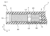
実施例1のガスセンサ1について、図1〜図4を用いて説明する。ガスセンサ1は、酸素を含むガスgに含まれる所定のガス成分の濃度を測定するために用いられる。図1に示すごとく、ガスセンサ1は、ガス室7と、基準ガス室8と、板状の固体電解質体2(2p,2m,2s)と、ポンプ電極30と、モニタ電極40と、センサ電極50と、基準電極80と、所定の厚みを有する板状のヒータ6とを備える。ガス室7には酸素を含むガスgが導入され、基準ガス室8には基準ガスが導入される。
Example 1
The
固体電解質体2は、ガス室7と基準ガス室8との間に設けられている。固体電解質体2は、ジルコニアやセリア等の、酸素イオン伝導性を有する材料からなる板状体である。
図1に示すごとく、固体電解質体2は所定の厚みdを有し、この厚みdを介して互いに対向する第1主面21と第2主面22を有する。ポンプ電極30とモニタ電極40とセンサ電極50とは、固体電解質体2におけるガス室7に曝される第1主面21に形成されている。また、基準電極80は、固体電解質体2における基準ガス室8に曝される第2主面22に形成されている。
ここで、固体電解質体2の厚みdとは、固体電解質体2の長手方向に5箇所の厚みを測定した際の平均値である。
ヒータ6は、ポンプ電極30とモニタ電極40とセンサ電極50および固体電解質体2に加えて基準電極80も加熱して、固体電解質体2の活性に必要な所定の温度まで上昇させる。なお、固体電解質体2の活性とは、固体電解質体2が酸素やNOxの濃度の測定に必要な温度に達したことを示し、NOx濃度の測定にはNOxを酸素イオンと窒素イオンとに分解する作用を有することを表している。
The
As shown in FIG. 1, the
Here, the thickness d of the
The
固体電解質体2とポンプ電極30と基準電極80とによって、ガスg中の酸素濃度を調整するポンプセル3を形成してある。また、図3に示すごとく、固体電解質体2とモニタ電極40と基準電極80とによって、ポンプセル3を使って酸素濃度を調整した後におけるガスg中の酸素濃度を検出するモニタセル4を形成してある。さらに、図1、図3に示すごとく、固体電解質体2とセンサ電極50と基準電極80とによって、ポンプセル3を使って酸素濃度を調整した後におけるガスg中の所定のガス成分の濃度を検出するセンサセル5を形成してある。具体的には、センサセル5は、所定のガス成分の濃度を示す信号を出力する。
The
ヒータ6は、基準ガス室8を挟んで固体電解質体2に対向配置されている。
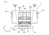
ヒータ6の厚さ方向(Z方向)において、固体電解質体2のうちポンプセル3を構成する部位2pからヒータ6までの距離D1と、固体電解質体2のうちモニタセル4を構成する部位2mからヒータ6までの距離D2と、固体電解質体2のうちセンサセル5を構成する部位2sからヒータ6までの距離D3とが、互いに等しくなっている。すなわち、ヒータ6は、セラミック製のヒータシート62と、該ヒータシート62の表面に形成され通電により発熱するヒータパターン63と、該ヒータパターン63を被覆する絶縁層61とからなる。距離D1は、固体電解質体2の主面22の一部であってポンプセル3を構成する部位2pの領域と、この主面22に対面する絶縁層61の主面90との間の最短距離であり、距離D2は、図3に示すように、固体電解質体2の主面22の一部であってモニタセル4を構成する部位2mの領域と絶縁層61の主面90の間の最短距離であり、距離D3は、固体電解質体2の主面22の一部であってセンサセル5を構成する部位2sの領域と絶縁層61の主面90の間の最短距離である。
The
In the thickness direction (Z direction) of the
本例のガスセンサ1は、自動車の排気ガスに含まれるNOx濃度を測定するための、NOxセンサとして機能する。すなわち、本例におけるガスgは内燃機関を有する自動車の排気ガスであり、所定のガス成分はNOxである。NOxの濃度を測定する際には、ガスセンサ1の全体を、図示しない筒状のケース内に収容し、これを自動車の排気管に取り付ける。この際、ガスセンサ1の先端部100を排気管内に差し込み、後端部を、基準ガスである大気に露出させる。
The
図1、図4に示すごとく、ガスセンサ1は、セラミック等からなる絶縁板10と、ガス室7を形成するためのシート状の第1スペーサ11と、固体電解質体2と、基準ガス室8を形成するためのシート状の第2スペーサ12と、ポンプセル3、モニタセル4及びセンサセル5を加熱するためのヒータ6とを、Z方向に積層している。
As shown in FIGS. 1 and 4, the
ガス室7は、自動車の排気管から排気ガス(ガスg)が導入される空間である。ガスgは、図1、図2に示すようにガス室7内を矢印250で示すような方向に流れる。図4に示すごとく、第1スペーサ11には切欠部79を形成してあり、この切欠部79がガス室7となる。また、第1スペーサ11には、拡散抵抗層13を設けてある。この拡散抵抗層13を通して、排気管からガス室7へガスgが導入される。拡散抵抗層13によって、ガスgの流入速度を制限している。
The
基準ガス室8は、酸素濃度が一定である基準ガスとしての大気が導入される空間で、前記第2スペーサ12に設けた貫通穴89により形成される。この貫通穴89は、ガスgの流れ方向X(すなわち、図1、図2に示すガス室7内を流れる方向250)に延びる溝からなる通路部121を介して、大気が存在するガスセンサ1の外部空間に連通している。この通路部121を通して、基準ガス室8に大気が導入される。なお、第1スペーサ11及び第2スペーサ12は、アルミナ等の絶縁材料よりなる。
The
ポンプ電極30とモニタ電極40とは、NOxに対する分解活性が低い金属材料から構成されている。具体的には、ポンプ電極30、モニタ電極40は、主成分として金Auと白金Ptとを含有する多孔質サーメット電極からなる。また、センサ電極50は、NOxに対する分解活性が高い金属材料から構成されている。具体的には、センサ電極50は、主成分として白金PtとロジウムRhとを含有する多孔質サーメット電極からなる。
The
図4に示すごとく、ポンプ電極30、モニタ電極40、センサ電極50、基準電極80は、電流の経路となるリード16を有している。また、第1スペーサ11、絶縁板10には、Z方向に貫通したスルーホール17が形成されており、このスルーホール17によって、ポンプ電極30、モニタ電極40、センサ電極50は絶縁板10の表面まで電気的に導通している。また、絶縁板10の表面には、外部機器と電気接続するためのリード接続電極15を複数個設けてある。
As shown in FIG. 4, the
ヒータ6は、セラミック製のヒータシート62と、該ヒータシート62の表面に形成され通電により発熱するヒータパターン63と、ヒータパターン63を被覆する絶縁層61とからなる。ヒータ6は、ヒータパターン63を外部からの給電により発熱させ、前記ポンプセル3、モニタセル4及びセンサセル5をそれぞれ活性化温度まで加熱するものである。また、ヒータシート62にはスルーホール17とパッド18とが形成されており、スルーホール17を通じて、ヒータパターン63とパッド18とが電気的に接続している。また、基準電極80も、スルーホール17を通じて、ヒータ62の表面に形成したリード接続電極180に電気接続されている。
The
また、ポンプセル3を使って多量の酸素を排出するために、ヒータパターン63の発熱中心が、ポンプセル3側に偏っている。すなわち、ポンプセル3の方が、モニタセル4やセンサセル5よりも高温になるように、ヒータパターン63を使って、ポンプセル3、モニタセル4、センサセル5を加熱している。
ここで、図1〜図3に示したように、固体電解質体2は厚みdを有する。また、ポンプ電極30とセンサ電極50とは、最短距離L2だけ離間している。本実施例では、前記最短距離L2と固体電解質体2の厚みdとの比率(L2/d)は3以上となるようにガスセンサ1は構成されている。
上述したように、固体電解質体2の厚みdは、板状の固体電解質体2の長手方向に5箇所の厚みを測定した際の平均値である。また、ポンプ電極30とセンサ電極50との最短距離L2は、ポンプ電極30とセンサ電極50とが形成された固体電解質体2のガスセンサ1の長手方向、すなわち、ガスgの流れ方向250に沿ったポンプ電極30とセンサ電極50との間隔である。
言い換えれば、ポンプ電極30とセンサ電極50との最短距離L2を固体電解質体2の厚みdに対して大きくすることにより比率3以上という条件が満足される。これによりポンプ電極30とセンサ電極50との間の抵抗が大きくなり、ポンプ電極30からセンサ電極50への電流のリークが低減される。これにより、ポンプセル3において必要な電流の流れが確保される。
また、固体電解質体2の厚みdをポンプ電極30とセンサ電極50との距離L2対して小さくすることにより比率3以上という条件が満足される。これにより、ポンプ電極30と、ポンプセル3を構成する基準電極80(すなわち基準電極80p)との間の抵抗が小さくなる。これにより、ポンプ電極30からセンサ電極50への電流のリークが低減され、センサセル5へのリーク電流の流入を抑制できる。したがって、所定ガス成分の濃度の測定の精度が向上する。
このようにポンプ電極30とセンサ電極50との最短距離L2の、固体電解質体2の厚みdに対する比率を3以上としたことで、ガスセンサ1は、1つの固体電解質体2のみで構成とすることができる。そして、この固体電解質体2に、ポンプ電極30、モニタ電極40、センサ電極50、及び基準電極80を形成することで、ポンプセル3、モニタセル4、センサセル5の3種類のセルを構成することができる。
また、ガスセンサ1の小型化の点から、前記最短距離L2は0.3mm〜0.7mmが好ましく、固体電解質体2の厚みdは0.1mm〜0.3mmが好ましい。さらに、前記最短距離L2と厚みdの比率(L2/d)は、7以下となるように構成することが好ましい。
各数値範囲は、固体電解質体2の強度、前記ポンプセル3、モニタセル4、センサセル5の機能上の観点から規定する。
前記したように、酸素を有するガスgの所定のガス成分(NOx)の濃度の測定は、ポンプセル3で酸素濃度が調整された後のガスgの残留酸素濃度をモニタセル4で測定し、所定のガス成分(NOx)の濃度と残留酸素濃度の合計に相当する酸素濃度をセンサセル5で測定し、センサセル5の出力とモニタセル4の出力の差分をとることにより、センサセル5の出力から残留酸素濃度に相当する成分を排除することにより行われる。
Further, since the
Here, as shown in FIGS. 1 to 3, the
As described above, the thickness d of the
In other words, by increasing the shortest distance L2 between the
Further, by reducing the thickness d of the
As described above, the ratio of the shortest distance L2 between the
Further, from the viewpoint of miniaturization of the
Each numerical range is defined from the viewpoint of the strength of the
As described above, the concentration of the predetermined gas component (NOx) of the gas g having oxygen is measured by measuring the residual oxygen concentration of the gas g after the oxygen concentration is adjusted by the
図1、図2に示すごとく、本実施例では、ガス室7は、第1スペーサ11、絶縁板10、固体電解質体2により形成される単一の空間からなっている。したがって、ガス室7内でのガスgの流れが円滑にでき、所定ガス成分の濃度を示すセンサセル5の出力の変動を高い応答性で検出することができる。
また、ガス室7は、ヒータ6の厚み方向(すなわちZ方向)に沿った所定の厚みと、所定の幅を有する単一の空間により形成さる。このガス室7の厚みは、少なくとも、固体電解質体2の主面21のポンプ電極30が形成された部分から主面21のモニタ電極40およびセンサ電極50が形成された部分まで一定となっている。ガス室7の幅は、ガス室7内でのガスの流れ方向250と厚み方向に直交する方向、すなわち、図2のY方向に沿った第1スペーサ11の内側壁間の間隔であり、すくなくとも、主面21のポンプ電極30が形成された部分から主面21のモニタ電極40およびセンサ電極50が形成された部分まで一定となっている。すなわち、ガス室7内における、ポンプ電極30からモニタ電極40及びセンサ電極50までの間には、絞り部や隔壁のように、ガス室7のZ方向寸法またはY方向寸法を狭くする物が存在しない。これにより、ガス室7内において、ガスgが、ポンプ電極30から、モニタ電極40及びセンサ電極50へ拡散律速することなく流れるようになる。
As shown in FIGS. 1 and 2, in this embodiment, the
The
また、図2に示すごとく、X方向(すなわちガスgが流れる方向250)における、ポンプ電極30からモニタ電極40までの距離L1と、ポンプ電極30からセンサ電極50までの距離L2とが互いに等しい。
2, the distance L1 from the
また、本例では図1、図4に示すごとく、基準電極80は、ポンプセル3とモニタセル4とセンサセル5において共用されている。すなわち、基準電極80は、ポンプセル3を構成する基準電極80pと、モニタセル4を構成する基準電極80mと、センサセル5を構成する基準電極80sとを一体的に有する単一の導体からなる。
In this example, as shown in FIGS. 1 and 4, the
次に、ガスセンサ1の所定ガスの濃度検出の動作原理について説明する。図1に示すごとく、ガスgは、拡散抵抗層13を通って、ガス室7に導入される。導入されたガスgには酸素分子が含まれるため、ポンプセル3を使って、酸素分子を排出する。すなわち、基準電極80とポンプ電極30との間に、基準電極80が高電位となるように直流電圧を加える。このようにすると、ポンプ電極30において酸素分子が還元されて酸素イオンとなり、ポンピング作用により基準ガス室8へ排出される。ポンプセル3に加える直流電圧の大きさを調整することにより、ガス室7内の酸素濃度を制御している。
Next, the operation principle of the
酸素濃度が低減したガスgは、モニタセル4とセンサセル5へ導入される。ガスgには、ポンプセル3において排出しきれなかった酸素分子が含まれているため、この酸素分子の濃度をモニタセル4によって測定する。図3に示すごとく、モニタセル4では、基準電極80とモニタ電極40との間に、基準電極80が高電位となるように直流電圧を加える。このようにすると、ガスgに含まれる酸素分子が還元されて酸素イオンとなり、ポンピング作用により基準ガス室8へ排出される。モニタ電極40は、NOxの分解に不活性なPt−Auサーメット電極であるため、モニタセル4に流れる酸素イオン電流は、ガスgに含まれる酸素分子の濃度のみに依存し、NOxの濃度には依存しない。したがって、電流計14を使って酸素イオン電流値を測定すれば、ガスgに含まれる酸素分子の濃度を測定できる。
The gas g having a reduced oxygen concentration is introduced into the
また、センサセル5においても、基準電極80とセンサ電極50との間に、基準電極80が高電位となるように直流電圧を加える。センサ電極50は、NOxの分解に活性なPt−Rhサーメット電極であるため、センサ電極50上において酸素分子とNOx分子とがそれぞれ還元されて酸素イオンとなり、ポンピング作用によって基準ガス室8へ排出される。したがって、電流計14を使って酸素イオン電流値を測定すれば、ガスgに含まれる酸素分子とNOx分子との合計の濃度を算出することができる。
Also in the
このように、モニタセル4を用いて、ガスgに含まれる酸素分子の濃度Aを測定し、センサセル5を用いて、酸素分子とNOx分子との合計の濃度Bを測定する。そして、前記濃度Bから前記濃度Aを減算することにより、ガスg中のNOxの濃度が算出される。
As described above, the concentration A of oxygen molecules contained in the gas g is measured using the
なお、本例では、ポンプセル3を使ってガスgから酸素を排出しているが、加える電圧の向きを逆にして、基準ガス室8からガスgへ酸素を導入してもよい。
In this example, oxygen is discharged from the gas g using the
本例の作用効果について説明する。
図1に示したように、固体電解質体2は厚みdを有する。また、ポンプ電極30とセンサ電極50とは、最短距離L2だけ離間している。
そして、最短距離L2と固体電解質体2の厚みdとの比率(L2/d)は3以上となるようにガスセンサ1は構成されている。言い換えれば、ポンプ電極30とセンサ電極50との距離L2を固体電解質体2の厚みdに対して大きくすることにより比率3以上という条件が満足される。これによりポンプ電極30とセンサ電極50との間の抵抗が大きくなり、ポンプ電極30からセンサ電極50への電流のリークが低減される。これにより、ポンプセル3において必要な電流の流れが確保される。また、固体電解質体2の厚みdをポンプ電極30とセンサ電極50との距離L2対して小さくすることにより比率3以上という条件が満足される。これにより、ポンプ電極30と、ポンプセル3を構成する基準電極80(すなわち基準電極80p)との間の抵抗が小さくなり、ポンプ電極30からセンサ電極50への電流のリークが低減され、ポンプセル3において必要な電流の流れが確保される。よって、所定ガス成分の濃度測定の精度が向上する。
これにより、1つの固体電解質体2を介してポンプセル3と、モニタセル4と、センサセル5を形成することが可能となる。そのため、固体電解質体2とヒータ6との間には、ガス室7と基準ガス室8とのいずれか一方のみが介在することになり、ヒータ7とポンプセル3と、モニタセル4と、センサセル5とヒータ6との距離を狭めることができ、ヒータ6によってポンプセル3、センサセル5及びモニタセル4を加熱しやすくなる。さらに、Z方向におけるガスセンサ1の厚みを小さくし、ガスセンサ1を小型化することができる。
また、図1、図3に示すごとく、ガスセンサ1においては、ヒータ6と固体電解質体2との間に、基準ガス室8が介在している。また、前記距離D1、D2、D3を互いに等しくしてある。
そのため、ポンプセル3と、モニタセル4と、センサセル5との3つのセルを、それぞれヒータ6に接近させることができる。すなわち、本例では、固体電解質体2とヒータ6との間に、基準ガス室8のみが介在するため、ポンプセル3、モニタセル4及びセンサセル5とヒータ6との間隔を狭めることができる。
また、ポンプセル3と、モニタセル4と、センサセル5を全てヒータ6から均等な距離に配置することで、ヒータ6からポンプセル3と、モニタセル4と、センサセル5へ伝達される熱エネルギーが均等となり、ポンプセル3と、モニタセル4と、センサセル5の温度ばらつきを小さくすることができる。また、ヒータ6によるポンプセル3と、モニタセル4と、センサセル5の加熱を必要最小限の消費電力で行うことができる。
The effect of this example will be described.
As shown in FIG. 1, the
The
As a result, the
As shown in FIGS. 1 and 3, in the
Therefore, the three cells of the
Further, by disposing the
また、本例のガスセンサ1は、1つの固体電解質体2とポンプ電極30、モニタ電極40、センサ電極50でそれぞれポンプセル3とモニタセル4とセンサセル5とを構成する。そのため、ガスセンサ1の製造コストを低減できる。
Moreover, the
図1、図2に示すごとく、ガス室7は、ヒータ6の厚み方向(すなわちZ方向)に沿った所定の厚みと、所定の幅を有する単一の空間により形成さる。このガス室7の厚みは、少なくとも、固体電解質体2の主面21のポンプ電極30が形成された部分から主面21のモニタ電極40およびセンサ電極50が形成された部分まで一定となっている。ガス室7の幅は、ガス室7内でのガスの流れ方向250と厚み方向に直交する方向、すなわち、図2のY方向に沿った第1スペーサ11の内側壁間の間隔であり、すくなくとも、主面21のポンプ電極30が形成された部分から主面21のモニタ電極40およびセンサ電極50が形成された部分まで一定となっている。すなわち、ガス室7内における、ポンプ電極30からモニタ電極40及びセンサ電極50までの間には、絞り部や隔壁のように、ガス室7のZ方向寸法またはY方向寸法を狭くする物が存在しない。これにより、ガス室7内において、ガスgが、ポンプ電極30から、モニタ電極40及びセンサ電極50へ拡散律速することなく流れるようになる。したがって、ガスg中の所定のガス成分(NOx)の濃度が変化したときに、その変化を短時間で検出することができる。すなわち、ガスセンサ1の出力の応答性を向上することができる。
As shown in FIGS. 1 and 2, the
また、本例のガスセンサ1は、ポンプセル3を構成する基準電極80pと、モニタセル4を構成する基準電極80mと、センサセル5を構成する基準電極80sとが単一の導体により形成されている。
そのため、図4に示すごとく、基準電極80から延びるリード16bをセル毎に設ける必要がなくなり、1本にして共通化することができる。そのため、ガスセンサ1の構成を簡素にすることが可能になる。また、ガスセンサ1をハウジングに組み込んでガスセンサアッセンブリを構成する場合、リード16bに通電部材を接続することになるが、前記構成にすると、リード16bを1本にできるため、前記通電部材も1本にすることができ、ガスセンサの構成を簡素にすることができる。
In the
Therefore, as shown in FIG. 4, it is not necessary to provide the lead 16b extending from the
また、本例では図2に示すごとく、X方向(すなわち、ガスgの流れ方向250)における、ポンプ電極30からモニタ電極40までの距離L1と、ポンプ電極30からセンサ電極50までの距離L2とが互いに等しい。そのため、ポンプセル3によって酸素濃度を低減されたガスgが、モニタ電極40とセンサ電極50とに略同時に到達する。したがって、モニタ電極40上におけるガスgの酸素濃度と、センサ電極50上におけるガスgの酸素濃度とが殆ど同一になる。そのため、上述したように濃度の減算(濃度B−濃度A)を行ったときに、酸素濃度を正確にキャンセルできるようになる。これにより、所定のガス成分の濃度を正確に測定することが可能になる。
また、ガス室7は、その中においてガスgが所定の方向250に流れるように構成されている。ポンプ電極30は、この所定の方向250の上流に位置する一方、モニタ電極40およびセンサ電極50は、この所定方向250の下流に位置する。また、モニタ電極40およびセンサ電極50は、所定方向250において並列的に配置されている、これにより、酸素を有するガスgの所定のガス成分(NOx)の濃度の測定は、ポンプセル3で酸素濃度が調整された後のガスgの残留酸素濃度を示すモニタセル4の出力と、所定のガス成分(NOx)の濃度と残留酸素濃度の合計に相当する酸素濃度を示すセンサセル5出力の差分における誤差を最小限にすることができ、所定ガス成分(NOx)濃度の測定精度を向上することができる。
In this example, as shown in FIG. 2, the distance L1 from the
The
なお、ポンプセル3は、モニタセル4やセンサセル5よりも流れる酸素イオンの量が多いため、ポンプセル3は、モニタセル4やセンサセル5よりも温度を高くすることが望ましい。そのため本例では、図4に示すようにヒータ6の最も高温となる位置をポンプセル3に近い位置にしている。これにより、ポンプセル3の温度を、モニタセル4やセンサセル5の温度よりも若干高くしている。
Since the
以上のごとく、本例によれば、所定ガス成分の濃度を示すセンサセル5の出力の変動を高い応答性で検出することができる。また、ポンプセル3、モニタセル4、センサセル5の温度ばらつきを小さくすることができ、ヒータ6の消費電力を低減できると共に、小型化が可能なガスセンサ1を提供することができる。
As described above, according to this example, it is possible to detect the fluctuation in the output of the
(実施例2)
図5に、実施例2にかかるガスセンサ1を示す。ガスセンサ1は、固体電解質体2を絶縁部材29を介して2つの固体電解質体2a、2bに分割している。一方の固体電解質体2aを用いてポンプセル3を構成し、他方の固体電解質体2bを用いてモニタセル4及びセンサセル5を構成する。Z方向における、一方の固体電解質体2aとヒータ6との距離Daと、他方の固体電解質体2bとヒータ6との距離Dbとは、互いに等しい。正確には、距離Daは、固体電解質体2aの主面22aと、この主面22aに対面する絶縁層61の主面90との間の最短距離であり、距離Dbは、固体電解質体2bの主面22bと、絶縁層61の主面90の間の最短距離である。
(Example 2)
FIG. 5 shows a
固体電解質体2a、2bの間には、絶縁部材29が介在している。本実施例のガスセンサ1は、流れる電流が相対的に大きいポンプセル3と、流れる電流が相対的に小さいモニタセル4及びセンサセル5とを独立した固体電解質体2aと固体電解質体2bとで構成している。そのため、ポンプセル3に流れた電流の一部がノイズ電流となって、モニタセル4及びセンサセル5に流れる不具合が最小限にされる。これにより、所定のガス成分の濃度測定の精度が向上する。本実施例では固体電解質体2を分割体として備えるが、この固体電解質体2の両主面に面してガス室7と基準ガス室8が形成され、固体電解質体2とヒータ7との間には基準ガス室8のみが介在することになり、ポンプセル3、モニタセル4、センサセル5とヒータ7との距離を小さくすることができ、ヒータ7によってこれらポンプセル3、モニタセル4、センサセルを加熱しやすくなる。
An insulating
その他の構成は、実施例1と同様である。また、図5に用いた符号のうち、実施例1において用いた符号と同一のものは、特に示さない限り、実施例1と同様の構成要素等を表す。 Other configurations are the same as those of the first embodiment. Further, among the symbols used in FIG. 5, the same symbols as those used in the first embodiment represent the same components as those in the first embodiment unless otherwise specified.
(実施例3)
図6に、実施例3にかかるガスセンサ1を示す。ガスセンサ1は、ヒータ6の位置において実施例1と異なる。すなわち、ヒータ6と固体電解質体2との間に、ガス室7が設けられている。そして、ヒータ6は、ガス室7を介して固体電解質体2に対向する。
(Example 3)
FIG. 6 shows a
その他の構成は、実施例1と同様である。また、図6に用いた符号のうち、実施例1において用いた符号と同一のものは、特に示さない限り、実施例1と同様の構成要素等を表す。
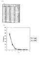
(実験例1)
ここで、図1〜3に示す実施例1のガスセンサを用いて、固体電解質体2の厚みdと、ポンプ電極30とセンサ電極50との最短距離L2とを種々変更して、この最短距離L2と厚みdとの比率(L2/d)の値とガスセンサのNOxガスの濃度検出精度の関係を調べた。
実験は、NOx濃度100ppm、O2濃度20%のガス環境下において、NOx濃度100ppmに相当するセンサセル5に流れる電流を基準(100%)と定義した時に、各寸法試料のセンサセル5に流れる電流との変化率を出力誤差とし、以下の式で定義した。
出力誤差(%)=((各寸法試料のセンサセル電流/基準としたセンサセル電流)−1)×100
図7(a)、(b)に実験結果を示すように、固体電解質体2の厚みdとポンプ電極30とセンサ電極50との最短距離L2の比率(L2/d)を3以上とすることで、出力誤差を2.5%以下に大きく低減することが可能であることがわかる。また、比率(L2/d)は3以上であれば出力誤差はより小さくできるが、上述のように、固体電解質体2の強度、前記ポンプセル3、モニタセル4、センサセル5の機能上の観点から7以下とすることが好ましい。
Other configurations are the same as those of the first embodiment. 6, the same reference numerals as those used in the first embodiment denote the same components as those in the first embodiment unless otherwise specified.
(Experimental example 1)
Here, by using the gas sensor of Example 1 shown in FIGS. 1 to 3, the thickness d of the
In the experiment, when a current flowing through the
Output error (%) = ((sensor cell current of each dimension sample / reference sensor cell current) −1) × 100
As shown in the experimental results in FIGS. 7A and 7B, the ratio (L2 / d) of the shortest distance L2 between the thickness d of the
1 ガスセンサ
2 固体電解質体
3 ポンプセル
30 ポンプ電極
4 モニタセル
40 モニタ電極
5 センサセル
50 センサ電極
6 ヒータ
7 ガス室
8 基準ガス室
80 基準電極
100 ガスセンサ先端部
g ガス
DESCRIPTION OF
Claims (6)
前記ガスが導入されるガス室(7)と、
基準ガスが導入される基準ガス室(8)と、
酸素イオン伝導性を有し、前記ガス室(7)と前記基準ガス室(8)との間に配置され、前記ガス室(7)に面する第1主面と、前記基準ガス室(8)に面する第2主面とを有する一つの板状の固体電解質体(2)と、
前記固体電解質体(2)の前記第1主面に形成された複数の電極(30、50)と、
前記固体電解質体(2)の前記第2主面に形成された基準電極(80)と、
前記固体電解質体(2)の前記第1主面に形成された前記電極の一つであり、前記基準電極(80)と前記固体電解質体(2)の一部(2p)とともに、前記ガス中の酸素濃度を調整するポンプセル(3)を構成するポンプ電極(30)と、
前記固体電解質体(2)の前記第1主面に形成された前記電極の一つであり、前記基準電極(80)と前記固体電解質体(2)の一部(2s)とともに、前記ポンプセル(3)によって酸素の濃度を調整した後における前記ガス中の所定ガス成分の濃度に応じた信号を出力するセンサセル(5)を構成するセンサ電極(50)と、
前記ガス室(7)又は前記基準ガス室(8)を介して前記固体電解質体(2)に対向配置されており、前記固体電解質体(2)を加熱する所定の厚みを有する板状のヒータ(6)と、を有し、
前記ポンプ電極(30)と前記センサ電極(50)との最短距離(L2)と、前記固体電解質体(2)の厚み(d)との比率(L2/d)が3以上であることを特徴とするガスセンサ。 A gas sensor (1) for measuring a concentration of a predetermined gas component of a gas containing oxygen,
A gas chamber (7) into which the gas is introduced;
A reference gas chamber (8) into which the reference gas is introduced;
A first main surface having oxygen ion conductivity, disposed between the gas chamber (7) and the reference gas chamber (8) and facing the gas chamber (7), and the reference gas chamber (8 A plate-like solid electrolyte body (2) having a second major surface facing
A plurality of electrodes (30, 50) formed on the first main surface of the solid electrolyte body (2);
A reference electrode (80) formed on the second main surface of the solid electrolyte body (2);
One of the electrodes formed on the first main surface of the solid electrolyte body (2), together with the reference electrode (80) and a part (2p) of the solid electrolyte body (2), in the gas A pump electrode (30) constituting a pump cell (3) for adjusting the oxygen concentration of
One of the electrodes formed on the first main surface of the solid electrolyte body (2), together with the reference electrode (80) and a part (2s) of the solid electrolyte body (2), the pump cell ( A sensor electrode (50) constituting a sensor cell (5) for outputting a signal corresponding to the concentration of a predetermined gas component in the gas after the oxygen concentration is adjusted by 3);
A plate-like heater having a predetermined thickness that is disposed to face the solid electrolyte body (2) via the gas chamber (7) or the reference gas chamber (8) and that heats the solid electrolyte body (2). (6)
The ratio (L2 / d) between the shortest distance (L2) between the pump electrode (30) and the sensor electrode (50) and the thickness (d) of the solid electrolyte body (2) is 3 or more. Gas sensor.
Priority Applications (1)
| Application Number | Priority Date | Filing Date | Title |
|---|---|---|---|
| JP2014168428A JP6203687B2 (en) | 2013-08-21 | 2014-08-21 | Gas sensor |
Applications Claiming Priority (3)
| Application Number | Priority Date | Filing Date | Title |
|---|---|---|---|
| JP2013171109 | 2013-08-21 | ||
| JP2013171109 | 2013-08-21 | ||
| JP2014168428A JP6203687B2 (en) | 2013-08-21 | 2014-08-21 | Gas sensor |
Related Child Applications (1)
| Application Number | Title | Priority Date | Filing Date |
|---|---|---|---|
| JP2016197201A Division JP6393722B2 (en) | 2013-08-21 | 2016-10-05 | Gas sensor |
Publications (3)
| Publication Number | Publication Date |
|---|---|
| JP2015062013A true JP2015062013A (en) | 2015-04-02 |
| JP2015062013A5 JP2015062013A5 (en) | 2016-01-21 |
| JP6203687B2 JP6203687B2 (en) | 2017-09-27 |
Family
ID=52483695
Family Applications (2)
| Application Number | Title | Priority Date | Filing Date |
|---|---|---|---|
| JP2014168428A Active JP6203687B2 (en) | 2013-08-21 | 2014-08-21 | Gas sensor |
| JP2016197201A Active JP6393722B2 (en) | 2013-08-21 | 2016-10-05 | Gas sensor |
Family Applications After (1)
| Application Number | Title | Priority Date | Filing Date |
|---|---|---|---|
| JP2016197201A Active JP6393722B2 (en) | 2013-08-21 | 2016-10-05 | Gas sensor |
Country Status (5)
| Country | Link |
|---|---|
| US (1) | US10036724B2 (en) |
| JP (2) | JP6203687B2 (en) |
| CN (1) | CN105474008B (en) |
| DE (1) | DE112014003820T5 (en) |
| WO (1) | WO2015025924A1 (en) |
Cited By (7)
| Publication number | Priority date | Publication date | Assignee | Title |
|---|---|---|---|---|
| US9523655B2 (en) | 2013-09-24 | 2016-12-20 | Denso Corporation | Gas concentration detector |
| WO2017104499A1 (en) * | 2015-12-17 | 2017-06-22 | 株式会社デンソー | Gas sensor |
| WO2017110553A1 (en) * | 2015-12-22 | 2017-06-29 | 株式会社デンソー | Internal-combustion engine gas concentration detecting device |
| JP2018100938A (en) * | 2016-12-21 | 2018-06-28 | 株式会社デンソー | Gas sensor element and gas sensor unit |
| JP2020003471A (en) * | 2018-06-26 | 2020-01-09 | 株式会社Soken | Gas sensor |
| US10921283B2 (en) | 2013-12-16 | 2021-02-16 | Denso Corporation | Gas sensor for detecting concentration of specific gas component |
| JP7299852B2 (en) | 2019-03-27 | 2023-06-28 | 日本碍子株式会社 | Sensor element and gas sensor |
Families Citing this family (20)
| Publication number | Priority date | Publication date | Assignee | Title |
|---|---|---|---|---|
| DE112014003820T5 (en) * | 2013-08-21 | 2016-05-04 | Denso Corporation | gas sensor |
| JP6169763B2 (en) * | 2013-12-16 | 2017-07-26 | 株式会社Soken | Gas sensor |
| JP6350359B2 (en) * | 2014-06-16 | 2018-07-04 | 株式会社デンソー | Gas sensor |
| JP6561719B2 (en) * | 2014-10-30 | 2019-08-21 | 株式会社デンソー | Gas sensor |
| JP6485364B2 (en) | 2015-02-12 | 2019-03-20 | 株式会社デンソー | Gas sensor |
| JP6382162B2 (en) | 2015-07-08 | 2018-08-29 | 株式会社Soken | Gas sensor pump electrode and reference electrode |
| JP6369496B2 (en) | 2015-09-17 | 2018-08-08 | 株式会社デンソー | Gas sensor |
| JP6731283B2 (en) * | 2016-05-11 | 2020-07-29 | 株式会社Soken | Gas sensor |
| CN109451749B (en) * | 2016-06-23 | 2021-05-14 | 日本碍子株式会社 | Gas sensor and method for measuring concentration of plurality of target components in gas to be measured |
| JP6849685B2 (en) | 2016-08-09 | 2021-03-24 | 日本碍子株式会社 | Gas sensor |
| JP6669616B2 (en) * | 2016-09-09 | 2020-03-18 | 日本碍子株式会社 | Gas sensor |
| JP6693405B2 (en) | 2016-12-20 | 2020-05-13 | 株式会社デンソー | Gas sensor element and gas sensor unit |
| JP6720851B2 (en) | 2016-12-21 | 2020-07-08 | 株式会社デンソー | Gas sensor element and gas sensor unit |
| JP6761369B2 (en) * | 2017-03-30 | 2020-09-23 | 日本碍子株式会社 | Gas sensor element |
| JP6998802B2 (en) * | 2018-03-12 | 2022-02-04 | 日本碍子株式会社 | Gas sensor |
| JP7006629B2 (en) * | 2019-01-31 | 2022-01-24 | 株式会社デンソー | Gas sensor |
| JP7010250B2 (en) * | 2019-01-31 | 2022-01-26 | 株式会社デンソー | Gas sensor |
| JP7118918B2 (en) | 2019-03-28 | 2022-08-16 | 株式会社Soken | gas sensor |
| CN113075278B (en) * | 2021-05-20 | 2022-08-02 | 中国科学技术大学先进技术研究院 | Nitrogen oxide sensor |
| CN113075277B (en) * | 2021-05-20 | 2022-08-02 | 中国科学技术大学先进技术研究院 | Nitrogen oxide sensor |
Citations (11)
| Publication number | Priority date | Publication date | Assignee | Title |
|---|---|---|---|---|
| JPH09105737A (en) * | 1994-10-24 | 1997-04-22 | Nippon Soken Inc | Air-fuel ratio detecting device |
| JP2000321238A (en) * | 1996-09-17 | 2000-11-24 | Riken Corp | Gas sensor |
| JP2003149199A (en) * | 2001-11-16 | 2003-05-21 | Nissan Motor Co Ltd | Gas sensor |
| JP2004125534A (en) * | 2002-09-30 | 2004-04-22 | Ngk Spark Plug Co Ltd | Gas sensor element and gas sensor using it |
| JP2004132840A (en) * | 2002-10-10 | 2004-04-30 | Denso Corp | Gas concentration detection device |
| US20040089054A1 (en) * | 2000-11-23 | 2004-05-13 | Berndt Cramer | Sensor element of a gas sensor |
| JP2005249718A (en) * | 2004-03-08 | 2005-09-15 | Okutekku:Kk | Nox concentration detecting sensor |
| JP2009150719A (en) * | 2007-12-19 | 2009-07-09 | Toyota Motor Corp | Nox sensor |
| JP2010048647A (en) * | 2008-08-21 | 2010-03-04 | Denso Corp | Nox sensor element |
| JP2012052901A (en) * | 2010-09-01 | 2012-03-15 | Nippon Soken Inc | Gas sensor and calibration method for the same |
| JP2013088119A (en) * | 2011-10-13 | 2013-05-13 | Nippon Soken Inc | Gas sensor element and gas sensor for internal combustion engine |
Family Cites Families (15)
| Publication number | Priority date | Publication date | Assignee | Title |
|---|---|---|---|---|
| JPS6036949A (en) | 1983-08-09 | 1985-02-26 | Ngk Insulators Ltd | Oxygen sensor element |
| US5360528A (en) * | 1992-07-20 | 1994-11-01 | General Motors Corporation | Wide range oxygen sensor |
| DE19539357B4 (en) | 1994-10-24 | 2011-09-15 | Denso Corporation | Air-fuel ratio detecting means |
| JP3544437B2 (en) * | 1996-09-19 | 2004-07-21 | 日本碍子株式会社 | Gas sensor |
| JP2001153840A (en) | 1999-11-24 | 2001-06-08 | Nippon Soken Inc | Gas sensor and detecting method for flammable gas constituent concentration |
| JP3501125B2 (en) | 2000-03-17 | 2004-03-02 | セイコーエプソン株式会社 | Electro-optical device |
| TWI301915B (en) | 2000-03-17 | 2008-10-11 | Seiko Epson Corp | |
| JP3973900B2 (en) | 2001-02-08 | 2007-09-12 | 株式会社日本自動車部品総合研究所 | Gas sensor element |
| JP2003083936A (en) | 2001-06-25 | 2003-03-19 | Denso Corp | Gas sensor element |
| JP4178885B2 (en) | 2002-08-30 | 2008-11-12 | 株式会社デンソー | Gas concentration detector |
| JP3979240B2 (en) | 2002-09-13 | 2007-09-19 | 株式会社デンソー | Gas concentration detector |
| JP2004125482A (en) | 2002-09-30 | 2004-04-22 | Denso Corp | Gas concentration detector |
| JP4931074B2 (en) | 2007-08-01 | 2012-05-16 | 日本特殊陶業株式会社 | Gas sensor and NOx sensor |
| JP4874282B2 (en) | 2008-03-20 | 2012-02-15 | 株式会社デンソー | Gas sensor control device |
| DE112014003820T5 (en) * | 2013-08-21 | 2016-05-04 | Denso Corporation | gas sensor |
-
2014
- 2014-08-21 DE DE112014003820.2T patent/DE112014003820T5/en active Pending
- 2014-08-21 CN CN201480045958.0A patent/CN105474008B/en active Active
- 2014-08-21 JP JP2014168428A patent/JP6203687B2/en active Active
- 2014-08-21 US US14/912,989 patent/US10036724B2/en active Active
- 2014-08-21 WO PCT/JP2014/071897 patent/WO2015025924A1/en active Application Filing
-
2016
- 2016-10-05 JP JP2016197201A patent/JP6393722B2/en active Active
Patent Citations (11)
| Publication number | Priority date | Publication date | Assignee | Title |
|---|---|---|---|---|
| JPH09105737A (en) * | 1994-10-24 | 1997-04-22 | Nippon Soken Inc | Air-fuel ratio detecting device |
| JP2000321238A (en) * | 1996-09-17 | 2000-11-24 | Riken Corp | Gas sensor |
| US20040089054A1 (en) * | 2000-11-23 | 2004-05-13 | Berndt Cramer | Sensor element of a gas sensor |
| JP2003149199A (en) * | 2001-11-16 | 2003-05-21 | Nissan Motor Co Ltd | Gas sensor |
| JP2004125534A (en) * | 2002-09-30 | 2004-04-22 | Ngk Spark Plug Co Ltd | Gas sensor element and gas sensor using it |
| JP2004132840A (en) * | 2002-10-10 | 2004-04-30 | Denso Corp | Gas concentration detection device |
| JP2005249718A (en) * | 2004-03-08 | 2005-09-15 | Okutekku:Kk | Nox concentration detecting sensor |
| JP2009150719A (en) * | 2007-12-19 | 2009-07-09 | Toyota Motor Corp | Nox sensor |
| JP2010048647A (en) * | 2008-08-21 | 2010-03-04 | Denso Corp | Nox sensor element |
| JP2012052901A (en) * | 2010-09-01 | 2012-03-15 | Nippon Soken Inc | Gas sensor and calibration method for the same |
| JP2013088119A (en) * | 2011-10-13 | 2013-05-13 | Nippon Soken Inc | Gas sensor element and gas sensor for internal combustion engine |
Cited By (9)
| Publication number | Priority date | Publication date | Assignee | Title |
|---|---|---|---|---|
| US9523655B2 (en) | 2013-09-24 | 2016-12-20 | Denso Corporation | Gas concentration detector |
| US10921283B2 (en) | 2013-12-16 | 2021-02-16 | Denso Corporation | Gas sensor for detecting concentration of specific gas component |
| WO2017104499A1 (en) * | 2015-12-17 | 2017-06-22 | 株式会社デンソー | Gas sensor |
| DE112016005780T5 (en) | 2015-12-17 | 2018-10-11 | Denso Corporation | gas sensor |
| WO2017110553A1 (en) * | 2015-12-22 | 2017-06-29 | 株式会社デンソー | Internal-combustion engine gas concentration detecting device |
| JP2018100938A (en) * | 2016-12-21 | 2018-06-28 | 株式会社デンソー | Gas sensor element and gas sensor unit |
| JP2020003471A (en) * | 2018-06-26 | 2020-01-09 | 株式会社Soken | Gas sensor |
| JP7138055B2 (en) | 2018-06-26 | 2022-09-15 | 株式会社Soken | gas sensor |
| JP7299852B2 (en) | 2019-03-27 | 2023-06-28 | 日本碍子株式会社 | Sensor element and gas sensor |
Also Published As
| Publication number | Publication date |
|---|---|
| US10036724B2 (en) | 2018-07-31 |
| CN105474008A (en) | 2016-04-06 |
| CN105474008B (en) | 2018-11-16 |
| JP6203687B2 (en) | 2017-09-27 |
| WO2015025924A1 (en) | 2015-02-26 |
| US20160209354A1 (en) | 2016-07-21 |
| JP2017040660A (en) | 2017-02-23 |
| DE112014003820T5 (en) | 2016-05-04 |
| JP6393722B2 (en) | 2018-09-19 |
Similar Documents
| Publication | Publication Date | Title |
|---|---|---|
| JP6393722B2 (en) | Gas sensor | |
| JP5253165B2 (en) | Gas sensor and nitrogen oxide sensor | |
| JP5367044B2 (en) | Gas sensor element and gas sensor for internal combustion engine | |
| WO2015030165A1 (en) | Gas concentration detection device | |
| JP3973900B2 (en) | Gas sensor element | |
| JP6352215B2 (en) | Gas sensor element | |
| WO2015029842A1 (en) | Gas concentration detection device | |
| JP2015230220A (en) | Gas sensor element | |
| JP3771569B2 (en) | NOx sensor | |
| JP2004151018A (en) | Laminated gas sensing element | |
| JP3973851B2 (en) | Gas sensor element | |
| JP2004132960A (en) | Gas sensor element | |
| WO2017195556A1 (en) | Gas sensor | |
| JP7379243B2 (en) | Gas sensor inspection device, gas sensor inspection method, and reference sensor | |
| US20180259478A1 (en) | Gas sensor | |
| JP4781950B2 (en) | Composite sensor element | |
| JP2004151017A (en) | Multilayer gas sensing element | |
| JP4563606B2 (en) | Multilayer sensor element | |
| JP2017133940A (en) | Gas sensor unit | |
| JP2002328112A (en) | Gas sensor element | |
| US9823220B2 (en) | NOx concentration detection apparatus and NOx concentration detection method | |
| JP6382178B2 (en) | Gas sensor | |
| JP6511405B2 (en) | Gas sensor | |
| JP3520217B2 (en) | Gas sensor | |
| JP2003149202A (en) | Composite sensor element |
Legal Events
| Date | Code | Title | Description |
|---|---|---|---|
| A621 | Written request for application examination |
Free format text: JAPANESE INTERMEDIATE CODE: A621 Effective date: 20150608 |
|
| A521 | Request for written amendment filed |
Free format text: JAPANESE INTERMEDIATE CODE: A523 Effective date: 20151130 |
|
| A977 | Report on retrieval |
Free format text: JAPANESE INTERMEDIATE CODE: A971007 Effective date: 20160303 |
|
| A131 | Notification of reasons for refusal |
Free format text: JAPANESE INTERMEDIATE CODE: A131 Effective date: 20160315 |
|
| A521 | Request for written amendment filed |
Free format text: JAPANESE INTERMEDIATE CODE: A523 Effective date: 20160513 |
|
| A02 | Decision of refusal |
Free format text: JAPANESE INTERMEDIATE CODE: A02 Effective date: 20160705 |
|
| A521 | Request for written amendment filed |
Free format text: JAPANESE INTERMEDIATE CODE: A523 Effective date: 20161005 |
|
| A911 | Transfer to examiner for re-examination before appeal (zenchi) |
Free format text: JAPANESE INTERMEDIATE CODE: A911 Effective date: 20161014 |
|
| RD03 | Notification of appointment of power of attorney |
Free format text: JAPANESE INTERMEDIATE CODE: A7423 Effective date: 20161221 |
|
| A131 | Notification of reasons for refusal |
Free format text: JAPANESE INTERMEDIATE CODE: A131 Effective date: 20170404 |
|
| A521 | Request for written amendment filed |
Free format text: JAPANESE INTERMEDIATE CODE: A523 Effective date: 20170602 |
|
| A131 | Notification of reasons for refusal |
Free format text: JAPANESE INTERMEDIATE CODE: A131 Effective date: 20170704 |
|
| A521 | Request for written amendment filed |
Free format text: JAPANESE INTERMEDIATE CODE: A523 Effective date: 20170802 |
|
| TRDD | Decision of grant or rejection written | ||
| A01 | Written decision to grant a patent or to grant a registration (utility model) |
Free format text: JAPANESE INTERMEDIATE CODE: A01 Effective date: 20170829 |
|
| A61 | First payment of annual fees (during grant procedure) |
Free format text: JAPANESE INTERMEDIATE CODE: A61 Effective date: 20170830 |
|
| R150 | Certificate of patent or registration of utility model |
Ref document number: 6203687 Country of ref document: JP Free format text: JAPANESE INTERMEDIATE CODE: R150 |
|
| R250 | Receipt of annual fees |
Free format text: JAPANESE INTERMEDIATE CODE: R250 |
|
| R250 | Receipt of annual fees |
Free format text: JAPANESE INTERMEDIATE CODE: R250 |
|
| R250 | Receipt of annual fees |
Free format text: JAPANESE INTERMEDIATE CODE: R250 |
|
| R250 | Receipt of annual fees |
Free format text: JAPANESE INTERMEDIATE CODE: R250 |