JP2015054153A - Nail printing equipment, and printing method for nail printing equipment - Google Patents
Nail printing equipment, and printing method for nail printing equipment Download PDFInfo
- Publication number
- JP2015054153A JP2015054153A JP2013190075A JP2013190075A JP2015054153A JP 2015054153 A JP2015054153 A JP 2015054153A JP 2013190075 A JP2013190075 A JP 2013190075A JP 2013190075 A JP2013190075 A JP 2013190075A JP 2015054153 A JP2015054153 A JP 2015054153A
- Authority
- JP
- Japan
- Prior art keywords
- nail
- writing instrument
- inclination angle
- unit
- head
- Prior art date
- Legal status (The legal status is an assumption and is not a legal conclusion. Google has not performed a legal analysis and makes no representation as to the accuracy of the status listed.)
- Pending
Links
Images


Abstract
Description
本発明は、ネイルプリント装置及びネイルプリント装置の印刷方法に関するものである。 The present invention relates to a nail printing apparatus and a printing method of the nail printing apparatus.
従来、ペン等の筆記具を装着した描画ヘッドを備え、筆記具の先端部を用紙(対象物)に当接させて描画を行うプロッタ方式のプリント装置が知られている(例えば、特許文献1参照)。
特許文献1には、用紙を載置するテーブルの床面に対する傾斜角度を検出し、この傾斜角度に応じて筆記具の筆圧、筆記具の下降速度及び描画ヘッドの移動速度を一定の値に保持する構成が開示されている。
特許文献1に記載の手法では、平面上に描画を施す場合に、斜め方向に関して速度を変えるため、テーブルの傾斜角の変化によって筆圧等が変化しないようにすることができる。
2. Description of the Related Art Conventionally, there is known a plotter-type printing apparatus that includes a drawing head equipped with a writing tool such as a pen and performs drawing by bringing the tip of the writing tool into contact with a sheet (object) (see, for example, Patent Document 1). .
In Patent Document 1, an inclination angle with respect to a floor surface of a table on which a sheet is placed is detected, and the writing pressure of the writing instrument, the descending speed of the writing instrument, and the moving speed of the drawing head are held at constant values according to the inclination angle. A configuration is disclosed.
In the method described in Patent Document 1, when drawing on a plane, the speed is changed in the oblique direction, so that the writing pressure or the like can be prevented from changing due to the change in the inclination angle of the table.
しかしながら、プロッタをネイルプリント装置として用いる場合には、描画対象が爪であるため、ペン等の筆記具の先端部を当接させる面が上下方向(高さ方向)に変化する。
このため、筆記具による描画速度が大きく変化し、爪の上に描画される線の太さや濃度が変化して、場合によっては線がかすれてしまい、綺麗なネイルプリントを施すことができないという問題がある。
なお、ネイルデザインは真上から片目で見るのではなく、両目で様々な角度から見るものであるため、曲面である爪の表面に印刷した際にデザインが歪んで見えないように画像補正を行う必要があるが、このような補正を行った場合でも爪の表面の角度に応じて爪上での筆記具の速度が速くなってしまうことは解消されない。
However, when the plotter is used as a nail printing apparatus, the object to be drawn is a nail, and the surface with which the tip of a writing instrument such as a pen abuts changes in the vertical direction (height direction).
For this reason, there is a problem that the drawing speed by the writing instrument is greatly changed, the thickness and density of the line drawn on the nail are changed, and the line is faint in some cases, and a beautiful nail print cannot be performed. is there.
In addition, since the nail design is not seen with one eye from right above, but with different angles with both eyes, image correction is performed so that the design is not distorted when printed on the surface of the nail, which is a curved surface. Although it is necessary, even when such correction is performed, the speed of the writing tool on the nail is not solved according to the angle of the nail surface.
また、比較的高さの低い爪の端部から比較的高さの高い爪の中央部に向かって描画するとき(すなわち、筆記具が爪の傾斜面を登る場合)には、筆記具によって爪が水平方向に強く押されてしまう場合がある。特に、筆記具の速度が速い場合には、筆記具によって押される力を強く感じやすい。筆記具によって爪が強く押される感じがあると、それによって指が動いてしまう場合があり、ネイルプリントの仕上がり品質が低下するという問題もある。 In addition, when drawing from the end of the nail having a relatively low height toward the center of the nail having a relatively high height (that is, when the writing tool climbs the inclined surface of the nail), the nail is leveled by the writing tool. It may be pushed strongly in the direction. In particular, when the speed of the writing instrument is high, it is easy to feel the force pressed by the writing instrument. If there is a feeling that the nail is strongly pressed by the writing instrument, the finger may move by this, and there is a problem that the finished quality of the nail print is lowered.
本発明は以上のような事情に鑑みてなされたものであり、傾斜角度の大きい爪の端部においても線が細くなったりかすれたりすることを防止するとともに、描画中に筆記具によって爪が押される感じを軽減し、筆記具に押される力によって指が動いてしまうことを防止して、高精細なネイルプリントを実現することのできるネイルプリント装置及びネイルプリント装置の印刷方法を提供することを目的とするものである。 The present invention has been made in view of the circumstances as described above, and prevents the line from becoming thin or blurred even at the end of the nail having a large inclination angle, and the nail is pushed by the writing tool during drawing. An object of the present invention is to provide a nail printing apparatus and a printing method of the nail printing apparatus that can realize high-definition nail printing by reducing the feeling and preventing the finger from moving due to the force pressed by the writing instrument. To do.
前記課題を解決するために、本発明のネイルプリント装置は、
爪の指をXY平面上に載置する指載置部と、
前記爪の表面の前記XY平面に対する傾斜角度を検出する傾斜角度検出部と、
前記指載置部に載置された前記指の爪に描画を施す筆記具を装着するヘッドと、
前記ヘッドをX方向及びY方向に移動させるヘッド駆動部と、
前記傾斜角度検出部により検出された前記爪の表面の傾斜角度に応じて前記ヘッドの移動速度を変更するように前記ヘッド駆動部を制御する制御部と、
を備えることを特徴としている。
In order to solve the above-mentioned problem, the nail printing apparatus of the present invention provides:
A finger placement unit for placing the finger of the nail on the XY plane;
An inclination angle detector for detecting an inclination angle of the surface of the nail with respect to the XY plane;
A head for mounting a writing instrument for drawing on the fingernail placed on the finger placement unit;
A head drive unit for moving the head in the X and Y directions;
A control unit that controls the head drive unit so as to change the moving speed of the head according to the tilt angle of the surface of the nail detected by the tilt angle detection unit;
It is characterized by having.
また、本発明のネイルプリント装置の印刷方法は、
筆記具を装着したヘッドをX方向及びY方向に移動させながらXY平面上に載置された指の爪に描画を施すネイルプリント装置の印刷方法において、
前記指の爪の表面の前記XY平面に対する傾斜角度を検出し、
検出された前記爪の表面の傾斜角度に応じて前記ヘッドの移動速度を変更して描画を施すことを特徴としている。
Further, the printing method of the nail printing apparatus of the present invention is:
In the printing method of the nail printing apparatus for drawing on the fingernail placed on the XY plane while moving the head equipped with the writing instrument in the X direction and the Y direction,
Detecting an inclination angle of the surface of the fingernail with respect to the XY plane;
The drawing is performed by changing the moving speed of the head according to the detected inclination angle of the surface of the nail.
本発明によれば、傾斜角度の大きい爪の端部においても線が細くなったりかすれたりすることを防止するとともに、描画中に筆記具によって爪が押される感じを軽減し、筆記具に押される力によって指が動いてしまうことを防止して、高精細なネイルプリントを実現することができる。 According to the present invention, it is possible to prevent the line from becoming thin or faint even at the end portion of the nail having a large inclination angle, and to reduce the feeling that the nail is pushed by the writing tool during drawing, and by the force pushed by the writing tool. The finger can be prevented from moving, and a high-definition nail print can be realized.
[第1の実施形態]
図1から図8を参照しつつ、本発明に係るネイルプリント装置1の第1の実施形態について説明する。なお、以下に述べる実施形態には、本発明を実施するために技術的に好ましい種々の限定が付されているが、本発明の範囲を以下の実施形態及び図示例に限定するものではない。
[First Embodiment]
A first embodiment of a nail print apparatus 1 according to the present invention will be described with reference to FIGS. The embodiments described below are given various technically preferable limitations for carrying out the present invention, but the scope of the present invention is not limited to the following embodiments and illustrated examples.
図1は、ネイルプリント装置1の内部構成を示す斜視図であり、図2は図1に示されたII−II線に沿った断面を矢印方向に見て示した断面図である。
図1及び図2に示すように、このネイルプリント装置1は、ケース本体2と、このケース本体2に収容される装置本体10と、を備えている。
FIG. 1 is a perspective view showing an internal configuration of the nail print apparatus 1, and FIG. 2 is a cross-sectional view showing a cross section taken along line II-II shown in FIG.
As shown in FIGS. 1 and 2, the nail print apparatus 1 includes a case
ケース本体2の前面上部一端には、後述する描画部40のペン等の筆記具41を交換するために開閉可能に構成された筆記具交換用蓋部23が設けられている。筆記具交換用蓋部23は、例えばヒンジ等を介して、図2に示すように閉状態から開状態まで回動自在となっている。
さらに、ケース本体2の一側面(本実施形態では、図1において左側面)であって後述する筆記具慣書部61に対応する位置には、筆記具慣書部61に載置される被描画媒体(図示せず)を入れ替え可能な媒体挿出口24が形成されている。
A writing
Further, a drawing medium placed on the writing instrument custom-designing
ケース本体2の上面(天板)には操作部25(図5参照)が設置されている。
操作部25は、ユーザが各種入力を行う入力部である。
操作部25には、例えば、ネイルプリント装置1の電源をONする電源スイッチ釦、動作を停止させる停止スイッチ釦、爪Tに描画するデザイン画像を選択するデザイン選択釦、描画開始を指示する描画開始釦等、各種の入力を行うための図示しない操作釦が配置されている。
An operation unit 25 (see FIG. 5) is installed on the upper surface (top plate) of the
The operation unit 25 is an input unit on which a user performs various inputs.
The operation unit 25 includes, for example, a power switch button for turning on the power of the nail printing apparatus 1, a stop switch button for stopping the operation, a design selection button for selecting a design image to be drawn on the nail T, and a drawing start for instructing a drawing start. Operation buttons (not shown) for performing various inputs such as buttons are arranged.
また、ケース本体2の上面(天板)のほぼ中央部には表示部26が設置されている。
表示部26は、例えば液晶ディスプレイ(LCD:Liquid Crystal Display)、有機エレクトロルミネッセンスディスプレイその他のフラットディスプレイ等で構成されている。
本実施形態において、この表示部26には、例えば、印刷指U1を撮影して得た爪画像(爪Tの画像を含む指画像)、この爪画像中に含まれる爪Tの輪郭線等の画像、爪Tに描画すべきデザイン画像を選択するためのデザイン選択画面、デザイン確認用のサムネイル画像、各種の指示を表示させる指示画面等が適宜表示される。
なお、表示部26の表面にタッチパネルが一体的に構成されていてもよい。この場合には、例えば、指先等でタッチパネル表面にタッチすることにより各種選択や指示を行うことができる。指以外でも例えばスタイラスペンや、先の尖った棒状の筆記具等によって表示部26の表面をタッチするタッチ操作によっても各種の入力を行うことができるように構成される。
In addition, a
The
In the present embodiment, the
A touch panel may be integrally formed on the surface of the
装置本体10は、ほぼ箱状に形成され、ケース本体2の内部下方に設置された下部機枠11と、この下部機枠11の上方で且つケース本体2の内部上方に設置されている上部機枠12と、を備えている。
The apparatus
まず、下部機枠11について説明する。
下部機枠11は、背面板111、底板112、左右一対の側板113a,113b、X方向移動ステージ収容部114、Y方向移動ステージ収容部115及び隔壁116を有する。
側板113a,113bの下端部は、底板112の左右両端部にそれぞれ連結され、側板113a,113bが底板112に対して立てられた状態に設けられている。
背面板111の下部は、前方(指挿入方向手前側)に向かって2段に窪むように形成されている。背面板111の下端部は底板112の前端部に連結されており、背面板111は、底板112と側板113a,113bによって囲われた領域を前後に区切っている。
この窪んだ背面板111の後ろ側に形成される空間がX方向移動ステージ収容部114、Y方向移動ステージ収容部115(図2参照)となっている。X方向移動ステージ収容部114内には、描画部40(図5参照)が前方(指挿入方向手前側)に移動した際に描画部40のX方向移動ステージ45が収容される。また、Y方向移動ステージ収容部115内には、描画部40のY方向移動ステージ47が配置されている。
また、隔壁116は、下部機枠11の内部前方側の空間(背面板111、底板112及び側板113a,113bによって囲われた指挿入方向手前側の空間)を上下に区切るように下部機枠11の内側に設けられている。隔壁116はほぼ水平に設けられ、隔壁116の左右両端部が側板113a,113bにそれぞれ連結され、隔壁116の後端部が背面板111に連結されている。
First, the
The
The lower ends of the
The lower part of the
The space formed on the back side of the recessed back
Further, the
この下部機枠11には、指固定部30が一体的に設けられている。
図3を参照して、指固定部30について説明する。
図3は図1に示されたIII−III線に沿った断面を矢印方向に見て示した断面図である。
The
The
FIG. 3 is a cross-sectional view showing a cross section taken along line III-III shown in FIG.
指固定部30は、描画を施す爪Tに対応する指(以下、これを「印刷指U1」という。)を受け入れる指受入部31と、この印刷指U1以外の指(以下、これを「非印刷指U2」という。)を退避させる指退避部32と、から構成されている。
指受入部31は、隔壁116の上側であって下部機枠11の幅方向のほぼ中央部に配置されている。また、隔壁116によって下部機枠11の下側に区分けられた空間が指退避部32を構成している。
例えば、薬指の爪Tに描画を施す場合には、図3に示すように、指受入部31に印刷指U1としての薬指を挿入し、非印刷指U2であるその他の4指(親指、人差し指、中指、小指)を指退避部32に挿入する。
指受入部31は、下部機枠11の前面側(印刷指挿入方向の手前側)に開口しており、下側が隔壁116の一部を構成する指載置部116a、両側が仕切り31a、奥側が仕切り31cによって区画されている。指載置部116aは、描画を施す爪Tの指(印刷指U1)をXY平面上に載置するものである。
また、指受入部31の上側は天井部31dによって区画されている。天井部31dには、指受入部31に挿入された印刷指U1の爪Tを露出させるための窓31eが形成されている。
The
The
For example, when drawing on the nail T of the ring finger, as shown in FIG. 3, the ring finger as the printing finger U1 is inserted into the
The
Further, the upper side of the
また、隔壁116の上面であって下部機枠11の前面側の両側部には、下部機枠11の前面側を塞ぐ前壁31f(図1参照)が立設されている。また、隔壁116の上面には、この前壁31fの中央部寄りの端部から前記指受入部31に向けて狭窄し、印刷指U1を指受入部31内に案内する一対のガイド壁31gが立設されている。
ユーザは指受入部31に挿入した印刷指U1と指退避部32に挿入した非印刷指U2との間に隔壁116を挟むことができる。そのため、指受入部31内に挿入された印刷指U1が安定して固定される。
なお、本実施形態では、隔壁116の前端部に下方向に張り出した突出部116bが形成されている。突出部116bは、手前側に向かうにつれてその厚さが漸減し、奥側に向かうにつれて漸増するテーパー部となっていてもよいし、突出部116bの厚さが、隔壁116の奥側の窪みに対して全体が厚い構造になっていてもよい。隔壁116の前端部に突出部116bが形成されていることにより、非印刷指U2が指退避部32に挿入された際、描画済みの指の爪Tと隔壁116との間に空間が確保され、爪Tが隔壁116の下面に接触して装置側にインクが付着したり、爪Tに描画された絵柄が擦れて損なわれたりするのを防止することができる。
Further,
The user can sandwich the
In the present embodiment, a protruding
隔壁116の上面であって、指受入部31の横(ケース本体2の媒体挿出口24に対応する位置であり、本実施形態では、図1において左側)には、後述する描画ヘッド42による描画可能範囲内に、後述する筆記具41の慣らし書きをするための筆記具慣書部61が設けられている。なお、筆記具慣書部61は、印刷指U1が指受入部31に挿入された際の爪Tの高さとほぼ同じとなる高さに設けられていることが好ましい。
筆記具慣書部61は、平板状の部分であり、前述のケース本体2の媒体挿出口24から挿入された図示しない被描画媒体が載置されるようになっている。
筆記具慣書部61に載置される被描画媒体は、ペン先412を慣らすことができるものであればよく、例えば紙片である。
筆記具慣書部61は、ペン先412が乾いていたりインクの乗りが悪い等により書き始めがかすれたりするのを防止するために、爪Tに画像データによる描画を開始する前に被描画媒体の上に筆記具41を下ろして「○」や「∞」等の所定の画像を描画して慣らし書きを行い、ペン先412の状態を良好にするためのものである。慣らし書きを行う際に描画する所定の画像は特に限定されないが、インクを無駄に使いすぎないよう、「○」や「∞」等の単純な画像であることが好ましい。「○」や「∞」等の慣らし書きは、筆記具慣書部61の範囲内で毎回少しづつずらしながら書くようにすることが好ましい。なお、被描画媒体のほぼ全面に書いてしまったときには、表示部26に「紙を交換して下さい」等の被描画媒体の交換を促す表示画面を表示させるようにする。この場合、ユーザが媒体挿出口24から被描画媒体を取り出して新しいものと交換することにより新しい被描画媒体に慣らし書きができる状態となる。もし、被描画媒体がロール紙である場合は、印刷スペースが無くなったときには、ロール紙から被描画媒体を繰り出し、新しい印刷面に慣らし書きを行えるようにする。
Drawing on the upper surface of the
The writing instrument
The drawing medium placed on the writing instrument
The writing
また、本実施例ではゴム製の筆記具キャップ62が筆記具慣書部61の前方(指挿入方向の手前側)に設置されている。筆記具キャップ62は、描画部40に装着される筆記具41に対応する数(本実施形態では4つ)だけ設けられており、描画部40に筆記具41を装着後であって描画を行っていないときには、筆記具キャップ62の真上に筆記具41を移動した後、後述するソレノイド440(図4参照)を引いて筆記具41を下降させ、ペン先412を筆記具キャップ62内に収容することで、非描画時におけるペン先412の乾燥を防止できるようになっている。なお、筆記具キャップ62の形状等は図示例に限定されず、例えば、描画部40に装着される全ての筆記具41のペン先412を受け入れることのできる長尺な溝状の筆記具キャップ等であってもよい。
なお、本実施形態では、このように、筆記具キャップ62が筆記具慣書部61の傍に設けられているので、描画を開始するときには、筆記具41を上昇させてすぐ傍の筆記具慣書部61で慣らし書きを行い、描画を開始することができる。このため、筆記具41の移動等にかかる時間を最小限に抑えることができ、迅速な描画動作を行うことができる。
Further, in this embodiment, a rubber
In the present embodiment, since the
描画部40は、描画用の筆記具41を備える描画ヘッド42、描画ヘッド42を支持するユニット支持部材44、描画ヘッド42をX方向(図1におけるX方向、ネイルプリント装置1の左右方向)に移動させるためのX方向移動ステージ45、X方向移動モータ46、描画ヘッド42をY方向(図2におけるY方向、ネイルプリント装置1の前後方向)に移動させるためのY方向移動ステージ47、Y方向移動モータ48等を備えて構成されている。
The
本実施形態において、描画ヘッド42は、それぞれ1本ずつ筆記具41を保持する筆記具キャリッジ43を4つ備えている。
図4(a)〜図4(c)は、筆記具キャリッジ43及びこれに支持された筆記具41を拡大した図であり、描画を行っているときの状態(描画状態)を示している。
図4(a)は、筆記具キャリッジ43及び筆記具41の側面図であり、図4(b)は、図4(a)の筆記具キャリッジ43及び筆記具41を矢視b方向から見た上面図であり、図4(c)は、図4(a)の筆記具キャリッジ43及び筆記具41を矢視c方向から見た正面図である。
In the present embodiment, the drawing
4A to 4C are enlarged views of the writing
FIG. 4A is a side view of the writing
図4(a)〜図4(c)に示すように、各筆記具キャリッジ43に保持される筆記具41は、筆記具軸部411の先端側にペン先412が設けられたものである。筆記具軸部411の内部は、各種インクを収容するインク収容部となっている。筆記具軸部411の内部に収容されるインクは、粘度や色材の粒径(粒子の大きさ)等は特に限定されず、例えば、金銀のラメ入りのインクや白色のインク、UV硬化型のインクやジェルネイル、アンダーコート用、トップコート用やマニキュア等も用いることが出来る。
筆記具軸部411の他端側には、筆記具軸部411よりも外側に張り出した鍔部413が形成された蓋部414が取り付けられている。筆記具軸部411及び蓋部414を形成する材料は特に限定されないが、筆記具41を量産するために適した樹脂等で形成されていることが好ましい。
本実施形態において、蓋部414の上部には、手やピンセット等でつまみ易いようにつまみ部415が設けられており、さらに、このつまみ部415には磁石に吸着するように小さな鉄片416が埋設、貼着等により設けられている。
As shown in FIG. 4A to FIG. 4C, the writing
On the other end side of the writing
In this embodiment, a
筆記具41は、例えばペン先412を爪Tの表面に押し当てることで筆記具軸部411内に収容されているインクが染み出して描画する、ペン先412がボールペンタイプとなったペンである。なお、筆記具41は、ボールペンタイプのものに限定されず、例えばフェルト状のペン先にインクを染み込ませて描画するサインペンタイプや、束ねた毛にインクを染み込ませて描画する筆ペンタイプのもの等であってもよい。また、ペン先412の太さも各種のものを用意することができる。
各筆記具キャリッジ421に保持される筆記具41は、同じタイプのペン先412を有するペンでもよいし、異なるタイプのペン先412を有する筆記具であってもよい。
筆記具41は後述するように筆記具キャリッジ43の筆記具保持部437d及び筆記具ホルダ431に上方から挿通するだけで保持されているため、ケース本体2に設けられている筆記具交換用蓋部23を開けて、例えば手やピンセットでつまみ部415を摘む、若しくは、図示しない棒状部材の先に磁石を取り付けたものをつまみ部415に近づけて鉄片416を磁石に吸着させて引き上げる等の手法により、簡易に交換が可能である。このため、ユーザは、各筆記具キャリッジ43に装着する筆記具41を、描画したいネイルデザインに応じてペン先412の種類やインクの種類の異なる筆記具41に適宜入れ替えることで、幅広いネイルデザインを実現することができる。
The writing
The writing
As will be described later, the writing
なお、本実施形態では、筆記具41を保持する筆記具キャリッジ43が装置の幅方向(左右方向、図1におけるX方向)に4つ並んでいるため、ペン先412の位置がX方向(装置の左右方向)にずれているが、このずれは描画動作における1ステップの整数倍になっており、描画に使われる筆記具41に応じて当該ずれている分のステップ数だけ補正して描画を行うため、4つの筆記具41は、同じ位置に描画を行うことができるようになっている。
In this embodiment, since four
各筆記具キャリッジ43には、筆記具41をほぼ垂直に保持する筆記具ホルダ431と、筆記具41を上下移動させるための筆記具上下機構432が設けられている。
筆記具ホルダ431は、内部にペン先412及び筆記具軸部411が挿通され、筆記具41を保持する筒状の部分である。
筆記具上下機構432は、ばね433によって前方(図2、図4(a)における右側方向)に付勢されており、ピストンのように往復運動をする円筒形のプランジャ434と、このばね433の付勢力に抗してプランジャ434を後方(図2、図4(a)における左側方向)に吸引するプル型のソレノイド440と、ソレノイドのプランジャ434の移動端側に取り付けられたピン436と、このピン436を介してプランジャ434と連結されている筆記具上下レバー437と、筆記具上下レバー437が上昇しすぎるのを抑制するストッパ438と、を備えている。銅線等を巻いたコイル部435の中で可動式のプランジャ434が動く仕組みになっている。コイル部435とプランジャ434のセットでソレノイド440になる。
筆記具上下レバー437は、図4(a)に示すように、短アーム437aと長アーム437bとがほぼ直角に交わるL字状の部材であり、短アーム437aの先端側にピン436に係止される長孔437cが形成されている。また、長アーム437bの先端側には、筆記具41が挿通される筆記具保持部437dが設けられている。筆記具保持部437dは、筆記具41の筆記具軸部411及びペン先412の径よりも大きく、筆記具41の鍔部413の径よりも小さい内径を有するリング状に形成されており、筆記具軸部411及びペン先412を挿通させるとともに鍔部413を下側から支持するように係止している。
筆記具上下レバー437における短アーム437aと長アーム437bとの交点には、筆記具キャリッジ43側から回転軸439が挿通されている。
Each writing
The writing
The writing tool up-and-
As shown in FIG. 4A, the writing tool up / down
A
本実施形態において、ソレノイド440が駆動されている状態では、図4(a)に示すように、ばね433の付勢力に抗してプランジャ434が後方に引かれた状態となり、プランジャ434のピン436に係止されている筆記具上下レバー437は長アーム437bがほぼ水平となる位置で保持される。この状態において、筆記具41のペン先は、筆記具キャリッジ43の筆記具ホルダ431よりも下方に下りた状態となり、爪Tの表面や被描画媒体と接触可能な描画状態となる。また、ソレノイド440が開放された状態では、ばね433の付勢力によってプランジャ434が前方に突出する。このとき、プランジャ434のピン436に係止されている筆記具上下レバー437は回転軸439を支点として上方向(反時計方向)に回動し、長アーム437bがストッパ438に当接して止まる。これにより、筆記具41の鍔部413が、筆記具上下レバー437によって上方向に跳ね上げられる(図2参照)。この状態において、筆記具41のペン先は、筆記具キャリッジ43の筆記具ホルダ431よりも上方に上がった状態となり、爪Tの表面や被描画媒体と接触しない非描画状態となる。
このように、ソレノイド440のプランジャ434を前後移動させる力は、回転軸439及びこれを支点として回動する筆記具上下レバー437によって筆記具41を上下移動させる力に変換される。
In this embodiment, when the
As described above, the force for moving the
なお、筆記具41は、筆記具キャリッジ43の筆記具ホルダ431に挿通されて保持されているのみであり、筆記具上下レバー437等に固定されていないため、自重によって下方に付勢されている。これにより、筆記具41は、鍔部413が筆記具保持部437dの上面に接触する位置まで、筆記具ホルダ431に沿って自由に下降できるとともに、爪Tの表面や被描画媒体に突き当たると、ペン先412が爪Tの表面や被描画媒体に押し当てられるようになっている。
すなわち、爪Tに筆記具41で描画する場合、ペン先412は、爪Tの表面形状(表面の起伏等)に追従して(爪Tの曲面や高さに合わせて)、印刷指U1が載置されているXY平面に直交するZ方向(すなわち上下方向)に自由に移動可能に構成されている。
例えば、爪Tの高さの低い部分(例えば爪Tの幅方向の両端部等)に描画する場合には、筆記具41は、鍔部413が筆記具保持部437dの上面に接触する位置近くまで下降し、爪Tの高さの高い部分(例えば、爪Tの幅方向の中央部等)に描画する場合には、筆記具41は、爪Tの高さに追従して上昇し、鍔部413が筆記具保持部437dの上面から離間する。
筆記具41の重量は数グラム〜数十グラムと極めて軽量であるため、ペン先412が爪Tに突き当たってもユーザが痛みを感じることはなく、また自重により筆記具41の筆圧は確保されるため爪Tの上等にネイルデザインを描くことができる。
Note that the writing
That is, when drawing with the writing
For example, when drawing on a portion where the height of the nail T is low (for example, both ends in the width direction of the nail T), the writing
Since the weight of the writing
本実施形態では、この筆記具上下機構432を構成する部材のうち、回転軸439及びストッパ438は、ステンレス等の金属で形成されており、それ以外の部材は、樹脂等の軽量で磁石に反応しない材料で形成されている。なお、筆記具上下機構432を構成する部材の材料は、ここに例示したものに限定されない。
また、本実施形態では、筆記具41を上下させるためのアクチュエータとしてソレノイド440を用いているが、筆記具41を上下させるためのアクチュエータは、ソレノイド440に限定されない。筆記具41は軽量であるため、ソレノイドの他、各種小型の駆動装置により筆記具41を上下させるためのアクチュエータを構成することができる。
In the present embodiment, the
In this embodiment, the
描画ヘッド42を支持するユニット支持部材44は、X方向移動ステージ45に取り付けれたX方向移動部451に固定されている。X方向移動部451は、X方向移動モータ46の駆動によりX方向移動ステージ45上を図示しないガイドに沿ってX方向に移動するようになっており、これにより、描画ヘッド42がX方向(図1におけるX方向、ネイルプリント装置1の左右方向)に移動するようになっている。
また、X方向移動ステージ45は、Y方向移動ステージ47のY方向移動部471に固定されている。Y方向移動部471は、Y方向移動モータ48の駆動によりY方向移動ステージ47上を図示しないガイドに沿ってY方向に移動するようになっており、これにより、描画ヘッド42がY方向(図2におけるY方向、ネイルプリント装置1の前後方向)に移動するようになっている。
なお、本実施形態において、X方向移動ステージ45及びY方向移動ステージ47は、X方向移動モータ46、Y方向移動モータ48と、図示しないボールネジ及びガイドとを組み合わせることで構成されている。本実施形態のX方向移動モータ46及びY方向移動モータ48は、1パルス送られるごとに40μm移動するステップモータである。
すなわち、本実施形態では、ベクトルデータとして表された画像データにおける描画の最小単位である「1ベクトル(40μm)」をステップモータであるX方向移動モータ46及びY方向移動モータ48における1ステップとしたときに、1ステップを移動させるために、描画制御部815からX方向移動モータ46及びY方向移動モータ48に1パルスの駆動信号を送り、40μmずつ筆記具41が移動する。
なお、本実施形態でX方向移動モータ46及びY方向移動モータ48の移動を40μm/ステップとしているのは、ネイルデザインを描画する場合、プリンタにおける「600dpi」程度の解像度で充分であり、当該解像度を実現しようとすると、25.4mm/600=42.333・・μmとなるためである。原理的には1μm/ステップ等で移動させることも可能ではあるが、このような精度の高いモータ制御を行うためには、装置の精度や剛性が要求されコストが高くなると同時に描画速度が遅くなる。このため、本実施形態のように40μm/ステップ程度とすることが好ましい。
本実施形態では、X方向移動モータ46及びY方向移動モータ48等により、爪Tに描画を施す筆記具41を備える描画ヘッド42をX方向及びY方向に駆動するヘッド駆動部49(図5参照)が構成されている。
The
The X
In this embodiment, the X
That is, in this embodiment, “1 vector (40 μm)”, which is the minimum unit of drawing in the image data represented as vector data, is defined as one step in the X
In the present embodiment, the movement of the
In the present embodiment, a
描画部40における筆記具41を上下移動させるためのソレノイド440、X方向移動モータ46、Y方向移動モータ48は、後述する制御装置80の描画制御部815(図5参照)に接続され、該描画制御部815によって制御されるようになっている。
本実施形態では、後述するように、描画対象である爪Tの表面の傾斜角度に応じて、描画制御部815が描画ヘッド42の移動速度を調整する。
A
In the present embodiment, as will be described later, the
図1及び図2に示すように、撮影部50は、上部機枠12に設けられている。
すなわち、上部機枠12には基板13が設置されており、この基板13の中央部下面には、撮像装置としてのカメラ51が2つ設置されている。カメラ51は、例えば200万画素程度以上の画素を有するものであることが好ましい。
カメラ51は、指受入部31内に挿入されている印刷指U1の爪Tを撮影して、印刷指U1の爪Tの画像である爪画像(爪Tの画像を含む指画像)を得るものである。
本実施形態では、2つのカメラ51は、指受入部31に挿入されている印刷指U1の爪Tの幅方向にほぼ並んで設けられている。2つのカメラ51のうち、一方のカメラ51は、指受入部31の底面に対向して設けられており、爪Tを真上から撮影するものである。また、他方のカメラ51は、指受入部31の底面に対して僅かに傾けて配置されており、爪Tを斜め上方向から撮影するものである。
また、基板13には、カメラ51を囲むように白色LED等の照明灯(照明装置)52が設置されている。照明灯52は、カメラ51による撮影の際に、印刷指U1の爪Tを照明するものである。撮影部50は、このカメラ51及び照明灯52を備えて構成されている。
この撮影部50は、後述する制御装置80の撮影制御部811(図5参照)に接続され、該撮影制御部811によって制御されるようになっている。
撮影部50によって撮影された画像の画像データは、後述する記憶部82の爪画像記憶領域821に記憶される。
As shown in FIGS. 1 and 2, the photographing
That is, a
The
In the present embodiment, the two
An illumination lamp (illumination device) 52 such as a white LED is installed on the
The photographing
Image data of an image photographed by the photographing
本実施形態では、撮像装置としての2つのカメラ51によって少なくとも2つの異なった位置・角度から爪Tを撮影することができ、少なくとも2枚の爪画像が取得される。
そして、これらの爪画像に基づいて、後述する爪情報検出部512が、爪Tの輪郭(爪Tの形状)の他、爪Tの表面の、XY平面に対する傾斜角度(以下「爪Tの傾斜角度」又は「爪曲率」という。)や爪Tの垂直位置等の爪情報を検出できるようになっている。すなわち、例えば、爪Tの真上からの画像と、爪Tの斜め上方向からの画像と、を取り込むことにより、爪Tの輪郭だけでなく、位置、爪Tの表面の傾斜角度を正確に検出することができる。
In this embodiment, the nail | Tail T can be image | photographed from at least 2 different positions and angles with the two
Then, based on these nail images, a nail information detecting unit 512, which will be described later, in addition to the contour of the nail T (the shape of the nail T), the inclination angle of the surface of the nail T with respect to the XY plane (hereinafter referred to as “the inclination of the nail T”). Nail information such as “angle” or “nail curvature”) and the vertical position of the nail T can be detected. That is, for example, by capturing an image from directly above the nail T and an image from an obliquely upward direction of the nail T, not only the contour of the nail T but also the position and the inclination angle of the surface of the nail T can be accurately determined. Can be detected.
また、制御装置80は、例えば上部機枠12に配置された基板13等に設置されている。
図5は、本実施形態における制御構成を示す要部ブロック図である。
制御装置80は、図5に示すように、図示しないCPU(Central Processing Unit)により構成される制御部81と、ROM(Read Only Memory)及びRAM(Random Access Memory)等(いずれも図示せず)で構成される記憶部82とを備えるコンピュータである。
Further, the
FIG. 5 is a principal block diagram showing a control configuration in the present embodiment.
As shown in FIG. 5, the
記憶部82には、ネイルプリント装置1を動作させるための各種プログラムや各種データ等が格納されている。
具体的には、記憶部82のROMには、爪画像から爪Tの形状や爪Tの傾斜角度等の爪情報を検出するための爪情報検出プログラム、描画データを生成するための描画データ生成プログラム、描画処理を行うための描画プログラム等の各種プログラムが格納されており、これらのプログラムが制御装置80によって実行されることによって、ネイルプリント装置1の各部が統括制御されるようになっている。
また、本実施形態において記憶部82には、撮影部50によって取得されたユーザの印刷指U1の爪Tの爪画像を記憶する爪画像記憶領域821、爪情報検出部812によって検出された爪情報が記憶される爪情報記憶領域822、及び爪Tに描画されるネイルデザインの画像データを記憶するネイルデザイン記憶領域823が設けられている。
The
Specifically, the ROM of the
Further, in the present embodiment, the
制御部81は、機能的に見た場合、撮影制御部811、爪情報検出部812、描画データ生成部813、表示制御部814、描画制御部815等を備えている。これら撮影制御部811、爪情報検出部812、描画データ生成部813、表示制御部814、描画制御部815等としての機能は、制御部81のCPUと記憶部82のROMに記憶されたプログラムとの共働によって実現される。
When viewed functionally, the
撮影制御部811は、撮影部50のカメラ51及び照明灯52を制御してカメラ51により、指受入部31に挿入された印刷指U1の爪Tの画像を含む指の画像(以下「爪画像」という。)を撮影させるものである。
本実施形態では、撮影制御部511は、2つのカメラ51によって異なる位置・角度(例えば、爪Tの真上と爪Tの斜め上方等)から少なくとも2枚の爪画像を取得させる。
撮影部50により取得された爪画像の画像データは、記憶部82に記憶されてもよい。
The
In the present embodiment, the imaging control unit 511 causes the two
The image data of the nail image acquired by the
爪情報検出部812は、カメラ51によって撮影された指受入部31に挿入された印刷指U1の爪Tの画像に基づいて、印刷指U1の爪Tについての爪情報を検出するものである。
ここで、爪情報とは、例えば、爪Tの輪郭(爪形状、爪Tの水平位置)、爪Tの表面の、XY平面に対する傾斜角度(爪Tの傾斜角度、爪曲率)、爪Tの高さ(爪Tの垂直方向の位置、以下「爪Tの垂直位置」又は単に「爪Tの位置」ともいう。)である。なお、爪Tの傾斜角度(爪曲率)とは、爪Tの幅方向における水平面(すなわち、印刷指U1が載置されている指載置部116aのXY平面)に対する角度をいう。本実施形態の爪情報検出部812は、爪画像に基づいて、これらの爪情報のうち、爪Tの輪郭(爪形状)及び爪Tの傾斜角度(爪曲率)を検出するようになっている。
The nail
Here, the nail information includes, for example, the contour of the nail T (nail shape, horizontal position of the nail T), the inclination angle of the surface of the nail T with respect to the XY plane (inclination angle of the nail T, nail curvature), Height (position of nail T in the vertical direction, hereinafter also referred to as “vertical position of nail T” or simply “position of nail T”). Note that the inclination angle (nail curvature) of the nail T refers to an angle with respect to the horizontal plane in the width direction of the nail T (that is, the XY plane of the
具体的には、爪情報検出部812は、カメラ51により取得された印刷指U1の爪Tの爪画像から、爪Tの輪郭(形状や大きさ)、位置を検出し、この輪郭をx,y座標等で表される情報として取得する。爪情報検出部812は、例えば、カメラ51により取得された印刷指U1の爪Tの爪画像から爪Tとそれ以外の指部分との色の違い等に基づいて爪Tの輪郭(形状)を検出するものである。なお、爪情報検出部812が爪Tの輪郭(形状)を検出する手法は特に限定されず、ここに挙げたものに限られない。
また、爪情報検出部812は、2つのカメラ51によって撮影された少なくとも2つの爪画像に基づいて、爪Tについて爪Tの傾斜角度(爪曲率)を検出する傾斜角度検出部として機能する。
爪情報検出部812は、例えば2つのカメラ51によって異なる位置・角度(例えば、爪Tの真上と爪Tの斜め上方等)から撮影された2つの爪画像からユーザの爪Tについて傾斜角度(爪曲率)を検出する。なお、爪情報検出部812が爪Tの傾斜角度(爪曲率)を検出する手法は特に限定されず、ここに挙げたものに限られない。
Specifically, the nail
The nail
For example, the nail
描画データ生成部813は、爪情報検出部812により検出された爪情報に基づいて、描画ヘッド42により印刷指U1の爪Tに施される描画用のデータを生成する。
具体的には、描画データ生成部813は、爪情報検出部812により検出された爪Tの形状等に基づいてネイルデザインの画像データを拡大、縮小、切出し等による合せ込み処理を行い、爪Tに描画を施すためのデータを生成する。
The drawing
Specifically, the drawing
また、本実施形態では、描画データ生成部813は、印刷対象である爪Tの傾斜角度(爪曲率)に応じて、ネイルデザインの画像データの曲面補正を行う。
図6(a)及び図6(b)は、画像データに曲面補正を行わない場合と曲面補正を行った場合との描画された画像の違いを概念的に示した説明図である。
爪Tに施されたネイルデザインは真上から片目で見るのではなく、両目で様々な角度から見るものであるため、曲面補正を行わずに描画すると、デザインが歪んで見えてしまう。
すなわち、ネイルデザインを描画する爪Tは幅方向に湾曲しているため、例えば、図6(a)に示すように、円の画像データを補正せずにそのまま爪Tに描いた場合には、円は爪Tの曲面に沿って爪Tの幅方向に引き伸ばされ、爪T上には横長の楕円として描かれ、人間が両目で見た場合にも楕円として見える。これに対して、図6(b)に示すように、元の円の画像データを爪Tの曲率を考慮して幅方向の長さが短くなるように(すなわち、全体として縦長の楕円の画像データとなるように)画像データに曲面補正を行って描画した場合には、爪T上には円が描画され、人間が両目で見ても円として見えるデザインを描くことができる。
In the present embodiment, the drawing
FIG. 6A and FIG. 6B are explanatory diagrams conceptually showing the difference between drawn images when the curved surface correction is not performed on the image data and when the curved surface correction is performed.
Since the nail design applied to the nail T is not seen with one eye from right above, but seen from various angles with both eyes, the design appears to be distorted when drawn without curved surface correction.
That is, since the nail T for drawing the nail design is curved in the width direction, for example, as shown in FIG. 6A, when the circle image data is directly drawn on the nail T without correction, The circle is stretched in the width direction of the nail T along the curved surface of the nail T, is drawn as a horizontally long ellipse on the nail T, and appears as an ellipse when viewed by both human eyes. On the other hand, as shown in FIG. 6B, the original circle image data is reduced in length in the width direction in consideration of the curvature of the nail T (that is, the image of a vertically long ellipse as a whole). When the image data is drawn by performing curved surface correction (as data), a circle is drawn on the nail T, and a design that looks like a circle even when viewed by both eyes can be drawn.
表示制御部814は、表示部26を制御して表示部26に各種の表示画面を表示させるものである。本実施形態では、表示制御部814は、例えばネイルデザインの選択画面やデザイン確認用のサムネイル画像、印刷指U1を撮影した指画像や指画像に含まれる爪画像、各種の指示画面等を表示部26に表示させるようになっている。
The
描画制御部815は、描画データ生成部813によって生成された描画データを描画部40に出力し、爪Tに対してこの描画データにしたがった描画を施すように描画部40のソレノイド440、X方向移動モータ46、Y方向移動モータ48を制御する制御部である。
本実施形態では、描画制御部815は、傾斜角度検出部として機能する爪情報検出部812により検出された爪Tの表面の傾斜角度が大きい部分では、爪Tの表面の傾斜角度が小さい部分よりも描画ヘッド42の移動速度を遅くするようにヘッド駆動部49(すなわち、筆記具41を備える描画ヘッド42をX方向及びY方向に移動させるX方向移動モータ46及びY方向移動モータ48)を制御する。
なお、傾斜角度に基づいて描画ヘッド42の移動速度を変える制御は、爪Tの幅方向(すなわち、横方向)、爪Tの延在方向(すなわち、縦方向)のいずれについても行ってもよいが、爪Tは横方向の中央部が高く側端部に行くにしたがって低くなる形状が一般的であるため、本実施形態では、爪Tの横方向の傾斜角度に対応した制御を行う場合を例示する。
また、このため、描画制御部815は、筆記具41をX方向に移動させるX方向移動モータ46を、爪Tの傾斜角度に応じて制御するようになっている。なお、爪Tの横方向及び縦方向の両方について傾斜角度に応じた制御を行う場合には、描画制御部815は、筆記具41をX方向に移動させるX方向移動モータ46及び筆記具41をY方向に移動させるY方向移動モータ48の両方を、爪Tの傾斜角度に応じて制御する。
The
In the present embodiment, the
Note that the control for changing the moving speed of the drawing
For this reason, the
ネイルプリント装置1の描画対象である爪Tは、筆記具41の先端部を当接させる面(爪Tの表面)が上下方向(高さ方向)に変化する。
このため、筆記具41の移動速度を一定にすると、爪Tの傾斜角度に応じて筆記具41による描画速度が大きく変化し、爪の上に描画される線の太さや濃度が変化して、場合によっては線がかすれてしまい、綺麗なネイルプリントを施すことができない。
すなわち、爪Tの表面が印刷指U1が載置されるXY平面に対してθ傾斜していると爪T上における筆記具41の速度は 1/COSθ となり、θ=30°の場合には1.15倍、θ=45°の場合には1.4倍、θ=60°の場合には2倍に達する。このため、筆記具41の移動速度を一定にした場合、爪Tの傾斜角度の大きい部分では、描画した線が細くなったり、色が薄く見えたり、かすれたりすることがあった。 なお、本実施形態では、前述のように、ネイルデザインの画像データに対して予め画像補正(曲面補正)を行うが、このような補正を行った場合でも爪Tの表面の傾斜角度に応じて爪T上における筆記具41の速度が速くなってしまうことは解消されない。
As for the nail T which is a drawing target of the nail printing apparatus 1, the surface (surface of the nail T) with which the tip of the writing
For this reason, when the moving speed of the writing
That is, when the surface of the nail T is inclined by θ with respect to the XY plane on which the printing finger U1 is placed, the speed of the writing
また、比較的高さの低い爪Tの端部から比較的高さの高い爪Tの中央部に向かって描画するとき(すなわち、筆記具41が爪Tの傾斜面を登る場合)には、筆記具41によって爪Tが水平方向に押されてしまう場合がある。特に、爪T上における筆記具41の速度が速い場合には、筆記具41の力を強く感じやすい。筆記具41によって爪Tが強く押される感じがあると、それによって印刷指U1が動いてしまう場合があり、ネイルプリントの仕上がり品質が低下する。
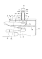
すなわち、図8に示すように、爪Tの表面が印刷指U1の載置されるXY平面に対してなす角度(爪Tの傾斜角度)θ=0°のときには、筆記具41からの力Pnは全て爪Tに水平な力成分P1であり、爪Tを垂直方向に押す力は筆記具の自重(または自重+ばねによる加圧)のみである。
これに対して、爪Tの傾斜角度θ=30°のときには、筆記具41からの力Pnの sin30°=0.50、すなわち半分の力が爪Tを垂直方向に押す力成分P2となり、爪Tの傾斜角度θ=45°のときには、筆記具41からの力Pnの sin45°=0.7071、すなわちほぼ7割の力が爪Tを垂直方向に押す力成分P2となり、爪Tの傾斜角度θ=60°のときには sin60°=0.8660が爪Tを垂直方向に押す力成分P2となり、筆記具41からの力Pnの8割以上の力が爪Tに掛かってしまう。
特に、θ=60°のときには爪Tにかかる力の Sin(60)=0.8660、すなわち0.866×0.866≒0.7500 の力が爪Tを水平方向(横方向)に押す力となってしまい、これが印刷指U1が動いてしまう原因となる。
In addition, when drawing from the end of the relatively low nail T toward the center of the relatively high nail T (that is, when the writing
That is, as shown in FIG. 8, when the angle formed by the surface of the nail T with respect to the XY plane on which the printing finger U1 is placed (the inclination angle of the nail T) θ = 0 °, the force Pn from the writing
On the other hand, when the inclination angle θ of the nail T is 30 °, sin30 ° = 0.50 of the force Pn from the writing
In particular, when θ = 60 °, the force applied to the nail T, Sin (60) = 0.8660, that is, a force of 0.866 × 0.866≈0.7500, is the force that pushes the nail T in the horizontal direction (lateral direction), and this is the printing finger It causes U1 to move.
このため、本実施形態では、描画制御部815は、傾斜角度検出部として機能する爪情報検出部812により検出された爪Tの表面の傾斜角度に応じて、ステップモータであるX方向移動モータ46及びY方向移動モータ48(本実施形態では、X方向移動モータ46)の駆動周波数を制御することにより、爪Tの傾斜角度が大きい部分では、爪Tの傾斜角度が小さい部分よりも筆記具41の移動速度が遅くなるように調整する。
具体的には、描画制御部815は、傾斜角度検出部として機能する爪情報検出部812により検出された爪Tの表面の傾斜角度(爪Tの曲面に関するデータ)から、筆記具41の各描画位置における爪Tの傾斜角度θを算出し、爪T上における筆記具41の速度が一定となるように、「Vp=V/COSθ」 (なお、V:θ=0°のときの筆記具41の速度(適正速度)、Vp:傾斜角度θでの筆記具41の速度、とする。) となるようにステップモータの駆動周波数(パルス幅、パルス間隔)を変更する。
前述のように、本実施形態のX方向移動モータ46及びY方向移動モータ48は、描画制御部815から1パルスの駆動信号が送られるごとに40μm移動するステップモータであり、通常250PPS(パルス/秒、T=4mS)で駆動しているとすると、ステップモータの駆動周波数:Fp=250COS(θ) と表すことができる。
この場合、例えば θ=30°のときには 250COS(30)=216.506≒217PPS とし、θ=45°のときには 177PPS とし、θ=60°のときには 125PPS とする。このように、爪Tの傾斜角度θが大きくなるのにしたがって筆記具41の移動速度を遅くすることにより、爪T上における筆記具41の速度を、傾斜角度に関わらずほぼ一定とすることができる。また、筆記具41から爪Tへの単位時間当たりの仕事量が減り、さらに、速度が遅くなることで筆記具41が押し上げられ易くなる。このため、筆記具41が爪Tの低いところから高いところに描画する(すなわち傾斜を登るとき)ときでも、爪Tが筆記具41で押される感じを低減することができ、描画中に印刷指U1が動いてしまうのを防止することができる。
For this reason, in the present embodiment, the
Specifically, the
As described above, the
In this case, for example, 250 COS (30) = 216.506≈217 PPS when θ = 30 °, 177 PPS when θ = 45 °, and 125 PPS when θ = 60 °. Thus, by slowing the moving speed of the writing
次に、本実施形態におけるネイルプリント装置1の動作及び使用方法について説明する。 Next, the operation and usage method of the nail print apparatus 1 in the present embodiment will be described.
このネイルプリント装置1により描画を行う場合、ユーザはまず、電源スイッチを入れて制御装置80を起動させる。
表示制御部814は、表示部26にデザイン選択画面を表示させる。ユーザは操作部25の操作釦251等を操作して、デザイン選択画面に表示された複数のネイルデザインの中から所望のネイルデザインを選択し、これにより、操作部25から選択指示信号が出力されて爪Tに描画すべきネイルデザインが選択される。
ネイルデザインが選択されると、制御部81は、当該選択されたネイルデザインを描画するのに必要な筆記具41を描画ヘッド42の所定の筆記具キャリッジ43にセットするよう促す指示画面を表示部26に表示させる。例えば、赤インク、ラメ入り金インクが必要であるときは、どの筆記具キャリッジ43にどのインクの筆記具41を装着すべきかを表示部26において指示する。ユーザは表示画面に表示された指示にしたがって、所定の筆記具キャリッジ43に所定の種類の筆記具41をセットする。なお、ユーザがあえて指示と異なる筆記具41をセットして、好みの色や質感のネイルデザインを実現するようにしてもよい。
なお、筆記具キャリッジ43にどの種類の筆記具41がセットされているかをバーコード等により制御部81が読み取ることができるように構成してもよく、この場合には、筆記具キャリッジ43にセットされている筆記具41によって描画できるネイルデザインを表示部26のデザイン選択画面を表示させ、ユーザにその中からネイルデザインを選択させるようにしてもよい。
次に、ユーザは、印刷指U1を指受入部31に挿入し、非印刷指U2を指退避部32に挿入して、印刷指U1を固定した上で、描画スイッチを操作する。
例えば、図3では、左手の薬指が印刷指U1として指受入部31に挿入され、その他の指が非印刷指U2として指退避部32に挿入されている例を示している。
When drawing with the nail printing apparatus 1, the user first turns on the power switch to activate the
The
When the nail design is selected, the
The
Next, the user inserts the printing finger U1 into the
For example, FIG. 3 shows an example in which the ring finger of the left hand is inserted into the
描画スイッチから指示が入力されると、描画動作を開始する前に、まず撮影制御部811が撮影部50を制御して、照明灯52により印刷指U1を照明しながら2つのカメラ51により印刷指U1を撮影させる。これにより、撮影制御部811は、指受入部31に挿入された印刷指U1の爪Tの画像(爪画像)を少なくとも2つ取得する。
次に、爪情報検出部812は、爪画像に基づいて爪Tの輪郭(爪形状)及び爪Tの傾斜角度(爪曲率)を検出する。
When an instruction is input from the drawing switch, before the drawing operation is started, the
Next, the nail
爪情報検出部812により爪Tの輪郭(爪形状)及び爪Tの傾斜角度(爪曲率)が検出されると、これらの爪情報に基づいて、描画データ生成部813が、ネイルデザインの画像データの爪Tへの合せ込み処理を行う。また、描画データ生成部813は、これら爪情報に基づいて、ネイルデザインの画像データにつき曲面補正を行う。これにより描画データが生成される。
また、描画制御部815は、爪Tへの描画開始前に、描画部40を筆記具慣書部61に移動させて、筆記具41を保持する筆記具キャリッジ43のソレノイド440を駆動させ、筆記具41を描画可能状態とする。そして、被描画媒体に「○」や「∞」等の所定の画像を描く慣らし書きを行う。なお、慣らし書きは、選択されたネイルデザインを描画するのに必要な筆記具41についてのみ行ってもよいし、全ての筆記具41について行ってもよい。
描画データが生成され、慣らし書きも完了すると、描画制御部815は、描画データを描画部40に出力し、描画に必要な筆記具41を保持する筆記具キャリッジ43のソレノイド440を駆動させて筆記具41を描画可能状態とするとともに、描画データに基づいて描画ヘッド42をXY方向に適宜移動させて爪Tに描画を行わせる。このとき、筆記具41は自重により爪Tの表面に押し当てられ、爪Tの表面形状に追従して上下動しながら描画を行う。
When the contour (nail shape) of the nail T and the inclination angle (nail curvature) of the nail T are detected by the nail
In addition, the
When the drawing data is generated and the break-in is completed, the
筆記具41による描画を行う間、描画制御部815は、傾斜角度検出部としての爪情報検出部812により検出された爪Tの傾斜角度(爪Tの曲面に関するデータ)から、筆記具41の各描画位置における爪Tの傾斜角度θをそれぞれ算出し、当該爪Tの傾斜角度θが大きい部分では、爪Tの傾斜角度θが小さい部分よりも筆記具41の移動速度が遅くなるようにヘッド駆動部(本実施形態では、X方向移動モータ46)の駆動周波数を随時切り替え制御する。
While drawing with the writing
なお、複数の指の爪Tに描画を施す場合には、1つの指の爪Tについて描画処理が終了した後、当該描画済みの爪Tの指を指受入部31から抜いて次に描画すべき爪Tの指を印刷指U1として指受入部31に挿入し、当該爪Tの爪画像を取得して、上記の処理を繰り返す。
なお、筆記具41を交換する場合には、描画制御部815は、描画ヘッド42を筆記具交換用蓋部23に対応する位置まで移動させる。この状態でユーザが筆記具交換用蓋部23を開けることにより、筆記具41の取り出し、交換が可能となる。
When drawing is performed on a plurality of fingernails T, after the drawing process for one fingernail T is completed, the finger of the drawn nail T is removed from the
Note that when the writing
以上のように、本実施形態のネイルプリント装置1によれば、爪Tに描画を施す筆記具41を備える描画ヘッド42をX方向及びY方向に移動させて爪Tに描画を施す場合に、傾斜角度検出部としての爪情報検出部812により検出された爪Tの傾斜角度に応じて、爪Tの傾斜角度θが大きい部分では、爪Tの傾斜角度θが小さい部分よりも筆記具41の移動速度が遅くなるようにヘッド駆動部を構成するX方向移動モータ46及びY方向移動モータ48を制御するようになっている。
このため、傾斜角度の大きい爪Tの端部において、このような移動速度の調整を行わない場合と比較して筆記具41から爪Tへの単位時間当たりの仕事量が減る。また、筆記具41の移動速度が遅くなることにより筆記具41が傾斜面を押し上げられ易くなる。このため、筆記具41が爪Tの低いところから高いところに描画する(すなわち傾斜を登るとき)ときでも、爪Tが筆記具41で押される感じを低減することができ、ユーザに対する負担が軽減されるとともに、筆記具41で押されることにより描画中に印刷指U1が動いてしまうのを防止することができ、線幅が細くなったり、かすれたりすること無く綺麗なネイルアートを施すことができる。
また、本実施形態では、ヘッド駆動部を構成するX方向移動モータ46及びY方向移動モータ48は、ステップモータであり、筆記具41の移動速度を調整する手法として、X方向移動モータ46及びY方向移動モータ48の駆動周波数を調整する手法を用いている。このため、簡易な制御により連続的に移動速度の調整を行うことができる。
また、筆記具41を用いて描画を行うため、従来のインクジェット方式の印刷ヘッドを用いる場合と比較して、粘度の高いインクや金銀のラメ入りのインクや白色のインク等のような各種の色材を含むインクを広く用いることができる。これにより、白色等の下地を塗らなくてもインクの色を綺麗に発色させることができ、下地を塗る手間を省くことができるとともに、爪Tの地の色等を生かしたデザインも描画することができるため、描画できるネイルデザインの幅が広がる。
また、アンダーコートやトップコート等を塗る場合や、爪Tの全体に色を塗りたい場合にも、ペン先412の太い筆記具41や筆ペンタイプの筆記具41等を用いれば、迅速かつむらなく塗ることができるため、ユーザが自分で下地等を塗る手間を省くことができるとともに、塗り残しや塗りむら等の発生による画質の低下が生じず、ネイルアートを美しく仕上げることができる。
また、使用できるインクが限定されないため、ラメ入りのインクを用いた豪華なデザインや、厚み感や光沢感があり、仕上がりに高級感があるデザイン等、ネイルサロンで施されるのと同様のバリエーション豊富で美しい仕上がりのネイルプリントをネイルプリント装置1によって簡易に爪Tに施すことができる。
また、例えばUV硬化型のジェルネイル等の粘度の高いインクもが使用できるため、ネイルサロンで施されるような、持ちがよく仕上がりの美しいネイルアートを実現することができる。
また、爪情報検出部812により、爪画像に基づいて、爪情報として爪の形状等を検出するため、ユーザの爪Tに合わせて描画を施すことができ、塗り残しやはみ出しのないきれいなネイルアートを実現することができる。
As described above, according to the nail print apparatus 1 of the present embodiment, when drawing is performed on the nail T by moving the drawing
For this reason, the amount of work per unit time from the writing
In this embodiment, the
Further, since drawing is performed using the
Also, when applying an undercoat, topcoat, or the like, or when it is desired to apply color to the entire nail T, use a
In addition, since the ink that can be used is not limited, the same variation as that applied at the nail salon, such as a luxurious design using lame ink, a design with a sense of thickness and gloss, and a luxurious finish An abundant and beautifully finished nail print can be easily applied to the nail T by the nail printing apparatus 1.
In addition, since a highly viscous ink such as UV curable gel nail can be used, it is possible to realize a nail art having a good finish and a beautiful finish, which is applied in a nail salon.
In addition, since the nail
[第2の実施形態]
次に、図9を参照しつつ、本発明に係るネイルプリント装置の第2の実施形態について説明する。なお、本実施形態は、描画ヘッドの筆記具の移動速度を調整する手法が第1の実施形態と異なるものであるため、以下においては、特に第1の実施形態と異なる点について説明する。
[Second Embodiment]
Next, a second embodiment of the nail print apparatus according to the present invention will be described with reference to FIG. Note that this embodiment is different from the first embodiment in the method of adjusting the moving speed of the writing tool of the drawing head, and therefore, the following description will focus on differences from the first embodiment.
本実施形態において、ステップモータであるX方向移動モータ46及びY方向移動モータ48は、描画制御部815から1パルスの駆動信号が送られるごとに10μm移動するようになっている。
また、本実施形態では、ベクトルデータとして表された画像データにおける描画の最小単位である「1ベクトル(40μm)」をステップモータであるX方向移動モータ46及びY方向移動モータ48における1ステップとしたときに、通常、傾斜角度のない部分に描画する場合には、40μmずつ筆記具41(筆記具41を搭載した描画ヘッド42)が移動するようになっている。すなわち、傾斜角度のない部分に描画する場合、1ステップを移動させるために、描画制御部815から4パルスの駆動信号が送られ、10μm×4=40μmずつ筆記具41が移動する。
In the present embodiment, the
In this embodiment, “1 vector (40 μm)”, which is the minimum unit of drawing in the image data represented as vector data, is defined as one step in the
また、描画制御部815は、爪Tの表面の傾斜角度が大きい部分では、爪Tの表面のXY平面に対する傾斜角度が小さい部分よりも、ステップモータであるX方向移動モータ46及びY方向移動モータ48の1ステップあたりのパルス数を少なくするようにヘッド駆動部を構成するX方向移動モータ46及びY方向移動モータ48を制御する。
これにより、爪Tの傾斜角度が大きい部分では、爪Tの傾斜角度が小さい部分よりも描画ヘッド42の筆記具41の移動速度が遅くなる。
In addition, the
Thereby, in the part where the inclination angle of the nail T is large, the moving speed of the
本実施形態では、描画対象となる爪Tの輪郭の範囲内の領域を、傾斜角度検出部としての爪情報検出部812により検出された爪Tの傾斜角度に基づいて複数の領域に分け、各領域ごとに描画ヘッド42の筆記具41の移動速度を変化させるようにヘッド駆動部を構成するX方向移動モータ46及びY方向移動モータ48を制御する。
なお、傾斜角度に応じた領域分類は、爪Tの幅方向(すなわち、横方向)、爪Tの延在方向(すなわち、縦方向)のいずれについても行ってもよいが、爪Tは横方向の中央部が高く側端部に行くにしたがって低くなる形状が一般的であるため、本実施形態では、爪Tの横方向を、爪Tの縦方向に沿ってほぼ平行する複数の領域に分ける場合を例示する。
また、このため、描画制御部815は、筆記具41をX方向に移動させるX方向移動モータ46を、爪Tの傾斜角度に応じて制御するようになっている。なお、爪Tの横方向及び縦方向の両方について傾斜角度に応じた制御を行う場合には、描画制御部815は、筆記具41をX方向に移動させるX方向移動モータ46及び筆記具41をY方向に移動させるY方向移動モータ48の両方を、爪Tの傾斜角度に応じて制御する。
In the present embodiment, the region within the contour range of the nail T to be drawn is divided into a plurality of regions based on the inclination angle of the nail T detected by the nail
The area classification according to the inclination angle may be performed in either the width direction (that is, the horizontal direction) of the nail T or the extending direction of the nail T (that is, the vertical direction). In the present embodiment, the lateral direction of the nail T is divided into a plurality of regions that are substantially parallel to the longitudinal direction of the nail T. The case is illustrated.
For this reason, the
具体的には、爪Tの輪郭の範囲内の領域を爪Tの傾斜角度θに応じて、「0°≦θ<29°」である領域(これを領域ar1とする。)、「29°≦θ<51°」である領域(これを領域ar2とする。)、「51°≦θ<67°」である領域(これを領域ar3とする。)、「θ≧67°」である領域(これを領域ar4とする。)の4種類に分けられており、各領域の区別(領域を区分けするための閾値)とそれぞれの領域に該当する場合の1ステップあたりのパルス数とは対応付けられて記憶部82等に記憶されている。描画制御部815は、この対応付けを参照しながら、各領域に応じた1ステップのパルス数となるようにX方向移動モータ46の制御を行う。
例えば、「0°≦θ<29°」のときには、1ステップにつき4パルスの駆動信号が描画制御部815から送られ、40μm/ステップずつ筆記具41が移動する。また、「29°≦θ<51°」のときには、1ステップにつき3パルスの駆動信号と1パルス分の休止信号が描画制御部815から送られ、30μm/ステップずつ筆記具41が移動する。また、「51°≦θ<67°」のときには、1ステップにつき2パルスの駆動信号と2パルス分の休止信号が描画制御部815から送られ、20μm/ステップずつ筆記具41が移動する。「θ≧67°」のときには、1ステップにつき1パルスの駆動信号と3パルス分の休止信号が描画制御部815から送られ、10μm/ステップずつ筆記具41が移動する。また、駆動信号のパルス数に応じて休止信号を入れているので、1ステップの時間は同じで移動量が変化する為筆記具41の移動速度が変化する。
なお、爪Tを何種類の領域に分けるかは特に限定されない。3種類以下の領域に分けてもよいし、5種類以上等、さらに細かい領域に分けてもよい。
Specifically, an area within the contour of the nail T is an area where “0 ° ≦ θ <29 °” according to the inclination angle θ of the nail T (this region is referred to as an area ar1), “29 °. ≦ θ <51 ° ”(this is a region ar2),“ 51 ° ≦ θ <67 ° ”(this is a region ar3), and“ θ ≧ 67 ° ” (This area is referred to as area ar4). Each area is distinguished from each other (threshold value for dividing the area) and the number of pulses per step corresponding to each area. And stored in the
For example, when “0 ° ≦ θ <29 °”, a drive signal of 4 pulses per step is sent from the
It should be noted that there are no particular restrictions on how many types of areas the nail T is divided into. It may be divided into three or less types of regions, or may be divided into finer regions such as five or more types.
ネイルデザインの画像データは、前述のようにベクトルデータとして表されており、描画の最小単位である「1ベクトル」をステップモータであるX方向移動モータ46及びY方向移動モータ48における1ステップとしたときに、1ステップ=40μmを基準としている。このため、上記のように爪Tの傾斜角度が大きくなるにしたがって1ステップあたりのパルス数を少なくするように制御を行った場合には、傾斜角度が大きい部分における筆記具41の移動速度を遅くして、爪Tの傾斜角度に関わらず爪T上における筆記具41の速度をほぼ一定とすることができるだけでなく、画像データの曲面補正も併せて行うことができる。
The image data of the nail design is expressed as vector data as described above, and “1 vector” which is the minimum unit of drawing is set as one step in the X
図9は、上記に示した例にしたがって爪Tの輪郭の範囲内の領域を分けた場合における各領域の1ステップの大きさを模式的に示した説明図である。
図9に示す例では、爪Tの中央部からある程度の範囲までは傾斜角度θが小さい(すなわち、「0°≦θ<29°」)領域ar1に分類されている。また、その両側の部分は「29°≦θ<51°」である領域ar2に分類され、さらにその両側の、爪Tの幅方向の端部は「51°≦θ<67°」である領域ar3に分類されている。なお、図9の例では、最も傾斜角度の大きい領域ar4に分類される領域がない爪Tとなっている。
図9に示すように、領域ar1に分類された爪Tの中央部及びその近傍では、描画制御部815は、1ステップにつき4パルスの駆動信号をX方向移動モータ46に対して送り、筆記具41は、40μm/ステップずつ移動する。また、領域ar2に分類された部分では、描画制御部815は、1ステップにつき3パルスの駆動信号をX方向移動モータ46に対して送り、筆記具41は、30μm/ステップずつ移動する。さらに、領域ar3に分類された爪Tの両側端部では、描画制御部815は、1ステップにつき2パルスの駆動信号をX方向移動モータ46に対して送り、筆記具41は、20μm/ステップずつ移動する。
FIG. 9 is an explanatory diagram schematically showing the size of one step in each area when the area within the contour of the nail T is divided according to the example described above.
In the example shown in FIG. 9, the inclination angle θ is small (that is, “0 ° ≦ θ <29 °”) from the central portion of the nail T to a certain range, and is classified into a region ar1. Further, the portions on both sides thereof are classified into a region ar2 where “29 ° ≦ θ <51 °”, and the ends in the width direction of the nail T on both sides thereof are regions where “51 ° ≦ θ <67 °”. It is classified as ar3. In addition, in the example of FIG. 9, it is the nail | Tail T without the area | region classified into area | region ar4 with the largest inclination angle.
As shown in FIG. 9, in the central portion of the nail T classified in the area ar1 and in the vicinity thereof, the
なお、その他の構成は、第1の実施形態と同様であることから、その説明を省略する。 Since other configurations are the same as those of the first embodiment, the description thereof is omitted.
次に、本実施形態におけるネイルプリント装置1の動作及び使用方法について説明する。 Next, the operation and usage method of the nail print apparatus 1 in the present embodiment will be described.
本実施形態のネイルプリント装置を用いて描画を行う場合、制御部81は、傾斜角度検出部としての爪情報検出部812により検出された爪Tの傾斜角度に基づいて、爪の表面を複数の領域(例えば図9に示す領域ar1〜領域ar3)に分類する。
筆記具41により描画を行う際には、描画制御部815は、記憶部82に記憶されている対応付けを参照しつつ、各領域ごとに描画ヘッド42の筆記具41の移動速度を変化させるようにヘッド駆動部を構成するX方向移動モータ46を制御する。
すなわち、爪Tの傾斜角度θが小さい領域(例えば領域ar1)では1ステップにつき4パルスの駆動信号をX方向移動モータ46に対して送り、筆記具41を40μm/ステップずつ移動させる。そして、爪Tの傾斜角度θが大きい領域(例えば領域ar3)ほど1ステップについてX方向移動モータ46に対して送るパルス数を少なくし、筆記具を少しずつ移動させる(例えば本実施形態の領域ar3では、1ステップについて2パルスの駆動信号を送り、筆記具41を20μm/ステップずつ移動させる。)。
これにより、爪Tの傾斜角度θが大きい領域では爪Tの傾斜角度θが小さい領域よりも筆記具41(描画ヘッド42)の移動速度が遅くなる。また、爪Tの傾斜角度θに基づいて1ステップあたりのパルス数が変更されるため、同時に曲面補正をも含んだ状態で描画を行うことができる。
When performing drawing using the nail print apparatus of the present embodiment, the
When drawing with the
That is, in a region where the inclination angle θ of the nail T is small (for example, the region ar1), a drive signal of 4 pulses per step is sent to the
Accordingly, the moving speed of the writing instrument 41 (drawing head 42) is slower in the region where the inclination angle θ of the nail T is large than in the region where the inclination angle θ of the nail T is small. In addition, since the number of pulses per step is changed based on the inclination angle θ of the nail T, it is possible to perform drawing while also including curved surface correction.
なお、その他の点については、第1の実施形態と同様であることから、その説明を省略する。 Since other points are the same as those in the first embodiment, description thereof is omitted.
以上のように、本実施形態によれば、第1の実施形態と同様の効果を得られる他、以下の効果を得ることができる。
すなわち、本実施形態では、描画制御部815は、爪Tの傾斜角度が大きい部分では、爪Tの傾斜角度が小さい部分よりもステップモータであるX方向移動モータ46の1ステップあたりの駆動パルス数を少なくするようにヘッド駆動部49を制御する。
このため、爪Tの傾斜角度θが大きい領域では爪Tの傾斜角度θが小さい領域よりも筆記具41(描画ヘッド42)の移動速度が遅くなり、傾斜角度の大きい爪Tの端部において、このような移動速度の調整を行わない場合と比較して筆記具41から爪Tへの単位時間当たりの仕事量が減る。また、筆記具41の移動速度が遅くなることにより筆記具41が傾斜面を押し上げられ易くなる。このため、筆記具41が爪Tの低いところから高いところに描画する(すなわち傾斜を登るとき)ときでも、爪Tが筆記具41で押される感じを低減することができ、ユーザに対する負担が軽減されるとともに、筆記具41で押されることにより描画中に印刷指U1が動いてしまうのを防止することができる。
また、本実施形態では、ヘッド駆動部49であるX方向移動モータ46及びY方向移動モータ48は、ステップモータであり、筆記具41の移動速度を調整する手法として、爪Tの傾斜角度θが大きい領域では爪Tの傾斜角度θが小さい領域よりもヘッド駆動部(本実施形態では、X方向移動モータ46)の1ステップあたりのパルス数を少なくするように制御する手法を用いている。このため、筆記具41の移動速度を調整することにより、同時に曲面補正を含んだ状態で描画を行うことができ、別途画像データに曲面補正を施す必要がない。通常、爪Tに描画を施す際には、描画前に画像データの曲面補正を行う必要がある。しかし、ベクトルで記載されている画像データについて曲面補正を行うためには、多くの演算とメモリが必要であり、場合によってはベクトルデータの分割なども必要となり演算量が増加する。本実施形態では、このような曲面補正を行うための処理時間を要しないとともに、制御構成を単純化することができる。
また、本実施形態では、爪Tの傾斜角度に基づいて爪Tの表面を複数の領域に分類し、この領域ごとに描画ヘッド42(描画ヘッドに搭載される筆記具41)の移動速度を変化させる。このため、描画しながら随時各描画位置における爪Tの傾斜角度を判断する場合と比較して処理を単純化することができる。
As described above, according to the present embodiment, the following effects can be obtained in addition to the same effects as those of the first embodiment.
In other words, in the present embodiment, the
For this reason, the moving speed of the writing instrument 41 (drawing head 42) is slower in the region where the inclination angle θ of the nail T is large than in the region where the inclination angle θ of the nail T is small. The amount of work per unit time from the writing
In the present embodiment, the
In the present embodiment, the surface of the nail T is classified into a plurality of regions based on the inclination angle of the nail T, and the moving speed of the drawing head 42 (the writing
なお、以上本発明の実施形態について説明したが、本発明は、かかる実施形態に限定されず、その要旨を逸脱しない範囲で、種々変形が可能であることは言うまでもない。 Although the embodiments of the present invention have been described above, the present invention is not limited to such embodiments, and various modifications can be made without departing from the scope of the present invention.
例えば、第1の実施形態では、各描画位置についてその都度爪Tの傾斜角度を求め、この傾斜角度に応じて描画ヘッド42の筆記具41の移動速度を変えるようにヘッド駆動部49を制御する構成としたが、例えば、第2の実施形態と同様に、爪Tを複数の領域に分類して、各領域種類ごとにステップモータの駆動周波数を変更し、筆記具41の移動速度を変えるように制御してもよい。
また、逆に、第2の実施形態では、爪Tを複数の領域に分類して、各領域種類ごとに筆記具41の移動速度を変えるようにヘッド駆動部49を制御する構成としたが、例えば、第1の実施形態と同様に、各描画位置についてその都度爪Tの傾斜角度を求め、この傾斜角度に応じて1ステップ辺りのパルス数を変更し、筆記具41の移動速度を変えるように制御してもよい。
For example, in the first embodiment, the inclination angle of the nail T is obtained each time for each drawing position, and the
Conversely, in the second embodiment, the nail T is classified into a plurality of regions, and the
また、描画部40の構成は、上記各実施形態に示したものに限定されない。
図10及び図11に、上記各実施形態とは異なる構成の描画部7を搭載したネイルプリント装置の一例を示す。
Moreover, the structure of the drawing
FIG. 10 and FIG. 11 show an example of a nail print apparatus equipped with a
図10は、ネイルプリント装置1の装置本体の正面図であり、図11は、図10におけるXI−XI線に沿った断面を矢印方向に見て示した断面図である。
図10及び図11に示すように、描画部7の描画ヘッド70は、複数(例えば8つ)の筆記具71を保持可能な回転式の筆記具キャリッジ72、筆記具キャリッジ72を回転させるキャリッジ回転機構73、筆記具キャリッジ72に保持された筆記具71を上下移動させるための筆記具上下機構74を備えている。
この場合、図10に示すように、ケース本体2の一側面であって後述する描画ヘッド70に対応する位置には、筆記具71の取り出し、交換を行うために開閉可能に構成された筆記具交換用蓋部23が設けられている。筆記具交換用蓋部23は、例えばヒンジ等を介して、図10に示すように閉状態から開状態まで回動自在となっている。
FIG. 10 is a front view of the apparatus main body of the nail print apparatus 1, and FIG. 11 is a cross-sectional view showing a cross section taken along line XI-XI in FIG.
As shown in FIGS. 10 and 11, the drawing
In this case, as shown in FIG. 10, the writing tool replacement is configured to be openable and closable so that the
本実施形態の筆記具キャリッジ72は、円筒状に形成され、筆記具71を保持する筆記具保持部721が、筆記具キャリッジ72の周方向に沿って複数(例えば8つ)配置されている。なお、筆記具71及びこれを保持する筆記具保持部721の数は特に限定されず、8つよりも多くてもよいし、これより少なくてもよい。多くの筆記具保持部721を備え、複数本の筆記具71を保持するほど、より複数のインクを用いた複雑なネイルデザインを描画することが可能となる。
なお、全ての筆記具保持部721に筆記具71が保持されている必要はなく、一部のみに筆記具71が保持されていてもよい。
筆記具キャリッジ72は、例えば、ステップモータにより構成されたキャリッジ回転機構73により、所定量ずつ回転可能に構成されており、描画に用いる筆記具71が選択されると、当該筆記具71が筆記具上下機構74の下方に位置するように筆記具キャリッジ72を回転させる。
筆記具上下機構74は、ソレノイド等により構成されており、描画時において筆記具上下機構74の下方に配置された筆記具71を爪Tの表面に接触する位置まで押し下げるようになっている。これにより、筆記具71は、ペン先が爪Tの表面に適度な力で押圧され、描画可能な状態となる。
なお、筆記具キャリッジ72を回転させるキャリッジ回転機構の構成、筆記具71を押し下げる筆記具上下機構の構成等は、ここに例示したものに限定されない。例えば、キャリッジ回転機構は、ラチェット機構とソレノイド等で構成されていてもよい。
The writing
Note that the writing implements 71 need not be held in all the writing implement holding
The writing
The writing tool up-and-
The configuration of the carriage rotation mechanism that rotates the writing
上記構成のネイルプリント装置には、前述のように、複数種類(本実施形態では最大8種類)の筆記具71を同時に保持させて描画を行うことができる。このため、例えば、7色のインクを必要とするレインボー柄や、段階的に濃さの異なる複数のインクを必要とするグラデーション柄、各種の色を用いたアーガイル柄等、多色を必要とする複雑かつ繊細なデザインでも簡易に描画することができる。 As described above, the nail print apparatus having the above-described configuration can perform drawing while simultaneously holding a plurality of types of writing tools 71 (up to eight types in the present embodiment). For this reason, for example, a rainbow pattern that requires seven colors of ink, a gradation pattern that requires a plurality of inks having different densities in stages, and an argyle pattern that uses various colors are required. Even complicated and delicate designs can be drawn easily.
また、上記各実施形態では、筆記具41を上下移動させる筆記具上下機構としてソレノイドを用いた構成を例示しているが、筆記具上下機構の構成はこれに限定されない。例えば、ステップモータ、DCモータ、モータ及びボールネジ等により構成してもよい。
Moreover, in each said embodiment, although the structure which used the solenoid was illustrated as a writing tool up-and-down mechanism which moves the
また、上記各実施形態では、描画ヘッド42を移動させるためのX方向移動ステージ45及びY方向移動ステージ47を、ステップモータであるX方向移動モータ46、Y方向移動モータ48と、図示しないボールネジ及びガイドとの組み合わせにより構成する例を示したが、描画ヘッド42を移動させるための構成はこれに限定されない。
X方向移動モータ46、Y方向移動モータ48は、描画ヘッド42を前後左右に随意に動かせるものであればよく、例えば、従来の安価なプリンタ等に用いられているようなシャフトやガイドとワイヤーで構成された機構を用いた構成でもよいし、サーボモータ等を用いた構成でもよい。
In each of the above embodiments, the
The
また、本実施形態では、筆記具としてインクにより描画するものを例示したが、描画ヘッドに装着される筆記具は、インクを描画するものに限定されない。
例えば、無色や有色透明の液状糊を収容した筆記具を描画ヘッドに装着し、これを用いて描画した後、糊が乾く前に粉状のラメ等をふり掛けたり、ラインストーン等を貼着することにより、より豪華なネイルデザインを実現することもできる。
また、香料を含んだ液体等を収容した筆記具を描画ヘッドに装着し、これを用いて描画を行い、香り付きのネイルプリントを楽しむことができるようにしてもよい。
Further, in the present embodiment, the writing tool is illustrated as drawing with ink, but the writing tool attached to the drawing head is not limited to that drawing ink.
For example, a writing instrument containing colorless or colored transparent liquid glue is attached to the drawing head, and after drawing with this, it is sprinkled with powdery lame etc. before the glue dries, or a rhinestone is attached. As a result, a more luxurious nail design can be realized.
Alternatively, a writing instrument containing a liquid containing fragrance or the like may be attached to the drawing head, and drawing may be performed using the writing tool so that a scented nail print can be enjoyed.
また、上記各実施形態では、4本等、複数の筆記具を描画ヘッドに同時に装着できるものを例示したが、例えば、描画ヘッドに装着可能な筆記具を1本のみとし、必要に応じて適宜ユーザが手動で筆記具を交換する方式としてもよい。このようにすれば筆記具を備えるネイルプリント装置1を安価に実現することができる。
また、描画ヘッドに装着する筆記具を自動で交換する機構を実装してもよい。この場合には、例えば複数の筆記具を待機スペースに保持しておき、ここから自動で筆記具を選択して描画ヘッドに装着する。このような構成とすれば、更に装置に保持できる筆記具の本数を増やすことも可能となる。
Further, in each of the above embodiments, an example in which a plurality of writing tools, such as four, can be mounted on the drawing head at the same time has been illustrated. However, for example, only one writing tool can be mounted on the drawing head, It is good also as a system which replaces a writing instrument manually. In this way, the nail printing apparatus 1 having a writing instrument can be realized at low cost.
Further, a mechanism for automatically changing a writing instrument attached to the drawing head may be mounted. In this case, for example, a plurality of writing tools are held in the standby space, and the writing tools are automatically selected therefrom and attached to the drawing head. With such a configuration, it is possible to further increase the number of writing instruments that can be held in the apparatus.
また、上記各実施形態では、筆記具の慣書用に紙片である被描画媒体を用いる場合を例示したが、被描画媒体は紙に限定されない。また、被描画媒体はロール状のものを用いてもよい。この場合には、自動又は手動により被描画媒体を送り出すとともに巻き取る媒体送り機構を設ける。また、被描画媒体はロール状のものである場合には、媒体挿出口24に代えてロール状の被描画媒体を着脱するための媒体着脱口を設ける。
Moreover, although each said embodiment illustrated the case where the drawing medium which is a piece of paper was used for the customary writing instrument, the drawing medium is not limited to paper. The drawing medium may be a roll-shaped medium. In this case, a medium feeding mechanism for feeding and winding the drawing medium automatically or manually is provided. Further, when the drawing medium is a roll-shaped medium, a medium attachment / detachment opening for attaching / detaching the roll-shaped drawing medium is provided instead of the medium insertion /
また、上記各実施形態では、描画データ生成部813が、ネイルデザインの画像データについて曲面補正を行い、描画データを生成する場合を例としたが、描画データ生成部813が描画データを生成することは本発明の必須の構成要素ではない。例えば、描画データを別途生成せずに、描画制御部815において、ネイルデザインの画像データをLUT(Lookup Table)等により適宜変換しつつ描画ヘッドに出力して爪形状に合った描画を行うように描画制御を行ってもよい。
In each of the above embodiments, the drawing
また、上記各実施形態では、爪情報として爪Tの形状を検出し、これに基づいて描画データを生成する場合を例としたが、爪形状を検出することは本発明の必須の構成要素ではない。例えば、爪Tの中程にワンポイント柄を描画する場合のように、描画を行う上で爪Tの輪郭を抽出することが必須でない場合であれば、正確に爪Tの形状を認識する必要はなく、爪形状の検出を行うことなく描画を行うことができる。 In each of the above embodiments, the shape of the nail T is detected as the nail information, and the drawing data is generated based on the detected shape. However, detecting the nail shape is an essential component of the present invention. Absent. For example, if it is not essential to extract the contour of the nail T when drawing, as in the case of drawing a one-point pattern in the middle of the nail T, it is necessary to accurately recognize the shape of the nail T No, drawing can be performed without detecting the nail shape.
また、撮像装置は、静止画を撮影するカメラ51に限定されず、動画を撮影可能なものであってもよい。この場合、カメラによって動画を撮影し、撮影された動画から、爪Tの上面の画像を適宜切り出して、爪情報の検出に用いる。
The imaging device is not limited to the
また、上記各実施形態では、爪画像記憶領域821、爪情報記憶領域822、ネイルデザイン記憶領域823が制御装置80の記憶部82内に設けられている場合を例としたが、爪画像記憶領域821、爪情報記憶領域822、ネイルデザイン記憶領域823は制御装置80の記憶部82に設けられている場合に限定されず、別途記憶部が設けられていてもよい。
Further, in each of the above embodiments, the case where the nail
また、上記各実施形態では、指を1本ずつ装置に挿入して順次印刷を行うネイルプリント装置1を例としたが、複数本の指に対して同時に印刷を行うことのできる装置に本発明を適用することも可能である。
例えば、筆記具の稼動範囲を広げて描画可能範囲を大きくすることにより、複数の印刷指U1に同時に描画を施すことも可能となる。
In each of the above embodiments, the nail print apparatus 1 that performs printing sequentially by inserting fingers one by one into the apparatus is taken as an example. However, the present invention is applicable to an apparatus that can perform printing on a plurality of fingers simultaneously. It is also possible to apply.
For example, it is possible to simultaneously draw a plurality of printing fingers U1 by expanding the operating range of the writing instrument and increasing the drawing range.
以上本発明のいくつかの実施形態を説明したが、本発明の範囲は、上述の実施の形態に限定するものではなく、特許請求の範囲に記載された発明の範囲とその均等の範囲を含む。
以下に、この出願の願書に最初に添付した特許請求の範囲に記載した発明を付記する。付記に記載した請求項の項番は、この出願の願書に最初に添付した特許請求の範囲の通りである。
〔付記〕
<請求項1>
爪の指をXY平面上に載置する指載置部と、
前記爪の表面の前記XY平面に対する傾斜角度を検出する傾斜角度検出部と、
前記指載置部に載置された前記指の爪に描画を施す筆記具を装着するヘッドと、
前記ヘッドをX方向及びY方向に移動させるヘッド駆動部と、
前記傾斜角度検出部により検出された前記爪の表面の傾斜角度に応じて前記ヘッドの移動速度を変更するように前記ヘッド駆動部を制御する制御部と、
を備えることを特徴とするネイルプリント装置。
<請求項2>
前記ヘッド駆動部は、ステップモータを備えており、
前記制御部は、前記爪の表面の傾斜角度が大きい部分では、前記爪の表面の傾斜角度が小さい部分よりも前記ステップモータの駆動周波数を下げることで前記ヘッドの移動速度を遅くするようにヘッド駆動部を制御することを特徴とする請求項1に記載のネイルプリント装置。
<請求項3>
前記ヘッド駆動部は、ステップモータを備えており、
前記制御部は、前記爪の表面の傾斜角度が大きい部分では、前記爪の表面の傾斜角度が小さい部分よりも前記ステップモータの1ステップあたりのパルス数を少なくするようにヘッド駆動部を制御することを特徴とする請求項1に記載のネイルプリント装置。
<請求項4>
前記爪の表面を、前記傾斜角度検出部により検出された傾斜角度に基づいて複数の領域に分類し、
前記制御部は、前記領域ごとに前記ヘッドの移動速度を変化させるように前記ヘッド駆動部を制御することを特徴とする請求項1から請求項3のいずれか一項に記載のネイルプリント装置。
<請求項5>
筆記具を装着したヘッドをX方向及びY方向に移動させながらXY平面上に載置された指の爪に描画を施すネイルプリント装置の印刷方法において、
前記指の爪の表面の前記XY平面に対する傾斜角度を検出し、
検出された前記爪の表面の傾斜角度に応じて前記ヘッドの移動速度を変更して描画を施すことを特徴とするネイルプリント装置の印刷方法。
Although several embodiments of the present invention have been described above, the scope of the present invention is not limited to the above-described embodiments, but includes the scope of the invention described in the claims and equivalents thereof. .
The invention described in the scope of claims attached to the application of this application will be added below. The item numbers of the claims described in the appendix are as set forth in the claims attached to the application of this application.
[Appendix]
<Claim 1>
A finger placement unit for placing the finger of the nail on the XY plane;
An inclination angle detector for detecting an inclination angle of the surface of the nail with respect to the XY plane;
A head for mounting a writing instrument for drawing on the fingernail placed on the finger placement unit;
A head drive unit for moving the head in the X and Y directions;
A control unit that controls the head drive unit so as to change the moving speed of the head according to the tilt angle of the surface of the nail detected by the tilt angle detection unit;
A nail printing apparatus comprising:
<Claim 2>
The head drive unit includes a step motor,
The control unit reduces the moving speed of the head at a portion where the inclination angle of the claw surface is large by lowering the driving frequency of the step motor than at a portion where the inclination angle of the claw surface is small. The nail printing apparatus according to claim 1, wherein the driving unit is controlled.
<Claim 3>
The head drive unit includes a step motor,
The control unit controls the head driving unit so that the number of pulses per step of the step motor is smaller in a portion where the inclination angle of the nail surface is large than in a portion where the inclination angle of the nail surface is small. The nail printing apparatus according to claim 1.
<Claim 4>
Classifying the surface of the nail into a plurality of regions based on the inclination angle detected by the inclination angle detector;
4. The nail printing apparatus according to claim 1, wherein the control unit controls the head driving unit so as to change a moving speed of the head for each region. 5.
<Claim 5>
In the printing method of the nail printing apparatus for drawing on the fingernail placed on the XY plane while moving the head equipped with the writing instrument in the X direction and the Y direction,
Detecting an inclination angle of the surface of the fingernail with respect to the XY plane;
A printing method for a nail printing apparatus, wherein the drawing is performed by changing the moving speed of the head according to the detected inclination angle of the surface of the nail.
1 ネイルプリント装置
2 ケース本体
31 指受入部
40 描画部
41 筆記具
42 描画ヘッド
43 筆記具キャリッジ
46 X方向移動モータ
48 Y方向移動モータ
49 ヘッド駆動部
50 撮影部
51 カメラ
52 照明灯
80 制御装置
81 制御部
82 記憶部
116 隔壁
811 撮影制御部
812 爪情報検出部
813 描画データ生成部
814 表示制御部
815 描画制御部
821 爪画像記憶領域
822 爪情報記憶領域
823 デザイン画像記憶領域
T 爪
U1 印刷指
U2 非印刷指
DESCRIPTION OF SYMBOLS 1
Claims (5)
前記爪の表面の前記XY平面に対する傾斜角度を検出する傾斜角度検出部と、
前記指載置部に載置された前記指の爪に描画を施す筆記具を装着するヘッドと、
前記ヘッドをX方向及びY方向に移動させるヘッド駆動部と、
前記傾斜角度検出部により検出された前記爪の表面の傾斜角度に応じて前記ヘッドの移動速度を変更するように前記ヘッド駆動部を制御する制御部と、
を備えることを特徴とするネイルプリント装置。 A finger placement unit for placing the finger of the nail on the XY plane;
An inclination angle detector for detecting an inclination angle of the surface of the nail with respect to the XY plane;
A head for mounting a writing instrument for drawing on the fingernail placed on the finger placement unit;
A head drive unit for moving the head in the X and Y directions;
A control unit that controls the head drive unit so as to change the moving speed of the head according to the tilt angle of the surface of the nail detected by the tilt angle detection unit;
A nail printing apparatus comprising:
前記制御部は、前記爪の表面の傾斜角度が大きい部分では、前記爪の表面の傾斜角度が小さい部分よりも前記ステップモータの駆動周波数を下げることで前記ヘッドの移動速度を遅くするようにヘッド駆動部を制御することを特徴とする請求項1に記載のネイルプリント装置。 The head drive unit includes a step motor,
The control unit reduces the moving speed of the head at a portion where the inclination angle of the claw surface is large by lowering the driving frequency of the step motor than at a portion where the inclination angle of the claw surface is small. The nail printing apparatus according to claim 1, wherein the driving unit is controlled.
前記制御部は、前記爪の表面の傾斜角度が大きい部分では、前記爪の表面の傾斜角度が小さい部分よりも前記ステップモータの1ステップあたりのパルス数を少なくするようにヘッド駆動部を制御することを特徴とする請求項1に記載のネイルプリント装置。 The head drive unit includes a step motor,
The control unit controls the head driving unit so that the number of pulses per step of the step motor is smaller in a portion where the inclination angle of the nail surface is large than in a portion where the inclination angle of the nail surface is small. The nail printing apparatus according to claim 1.
前記制御部は、前記領域ごとに前記ヘッドの移動速度を変化させるように前記ヘッド駆動部を制御することを特徴とする請求項1から請求項3のいずれか一項に記載のネイルプリント装置。 Classifying the surface of the nail into a plurality of regions based on the inclination angle detected by the inclination angle detector;
4. The nail printing apparatus according to claim 1, wherein the control unit controls the head driving unit so as to change a moving speed of the head for each region. 5.
前記指の爪の表面の前記XY平面に対する傾斜角度を検出し、
検出された前記爪の表面の傾斜角度に応じて前記ヘッドの移動速度を変更して描画を施すことを特徴とするネイルプリント装置の印刷方法。 In the printing method of the nail printing apparatus for drawing on the fingernail placed on the XY plane while moving the head equipped with the writing instrument in the X direction and the Y direction,
Detecting an inclination angle of the surface of the fingernail with respect to the XY plane;
A printing method for a nail printing apparatus, wherein the drawing is performed by changing the moving speed of the head according to the detected inclination angle of the surface of the nail.
Priority Applications (1)
| Application Number | Priority Date | Filing Date | Title |
|---|---|---|---|
| JP2013190075A JP2015054153A (en) | 2013-09-13 | 2013-09-13 | Nail printing equipment, and printing method for nail printing equipment |
Applications Claiming Priority (1)
| Application Number | Priority Date | Filing Date | Title |
|---|---|---|---|
| JP2013190075A JP2015054153A (en) | 2013-09-13 | 2013-09-13 | Nail printing equipment, and printing method for nail printing equipment |
Publications (2)
| Publication Number | Publication Date |
|---|---|
| JP2015054153A true JP2015054153A (en) | 2015-03-23 |
| JP2015054153A5 JP2015054153A5 (en) | 2016-06-02 |
Family
ID=52818962
Family Applications (1)
| Application Number | Title | Priority Date | Filing Date |
|---|---|---|---|
| JP2013190075A Pending JP2015054153A (en) | 2013-09-13 | 2013-09-13 | Nail printing equipment, and printing method for nail printing equipment |
Country Status (1)
| Country | Link |
|---|---|
| JP (1) | JP2015054153A (en) |
Cited By (3)
| Publication number | Priority date | Publication date | Assignee | Title |
|---|---|---|---|---|
| US10736400B2 (en) | 2018-10-04 | 2020-08-11 | Casio Computer Co., Ltd. | Nail printing device, nail printing method, and recording medium |
| CN112586859A (en) * | 2021-01-08 | 2021-04-02 | 上海魅奈儿科技有限公司 | Hand groove device of nail machine and nail machine |
| US11517095B2 (en) | 2018-10-04 | 2022-12-06 | Casio Computer Co., Ltd. | Printing device and printing method |
Citations (8)
| Publication number | Priority date | Publication date | Assignee | Title |
|---|---|---|---|---|
| JPH07266789A (en) * | 1994-03-31 | 1995-10-17 | Mutoh Ind Ltd | Flat plotter |
| JP2000184790A (en) * | 1998-12-15 | 2000-06-30 | Funai Electric Co Ltd | Motor controller |
| JP2001010032A (en) * | 1999-06-30 | 2001-01-16 | Canon Inc | Stereoscopic surface printer, contact type printhead and method for printing by stereoscopic surface printer |
| JP2001239652A (en) * | 2000-02-28 | 2001-09-04 | Minolta Co Ltd | Printer and printing method |
| JP2002165632A (en) * | 2000-11-30 | 2002-06-11 | Matsushita Electric Works Ltd | Nail art printer |
| JP2009000818A (en) * | 2007-06-19 | 2009-01-08 | Hitachi Omron Terminal Solutions Corp | Printer |
| JP2010102527A (en) * | 2008-10-24 | 2010-05-06 | Seiko Epson Corp | Printing control device, printing control method, and printing control program |
| JP2012232414A (en) * | 2011-04-28 | 2012-11-29 | Casio Computer Co Ltd | Curved surface printing apparatus, and print control method of the same |
-
2013
- 2013-09-13 JP JP2013190075A patent/JP2015054153A/en active Pending
Patent Citations (8)
| Publication number | Priority date | Publication date | Assignee | Title |
|---|---|---|---|---|
| JPH07266789A (en) * | 1994-03-31 | 1995-10-17 | Mutoh Ind Ltd | Flat plotter |
| JP2000184790A (en) * | 1998-12-15 | 2000-06-30 | Funai Electric Co Ltd | Motor controller |
| JP2001010032A (en) * | 1999-06-30 | 2001-01-16 | Canon Inc | Stereoscopic surface printer, contact type printhead and method for printing by stereoscopic surface printer |
| JP2001239652A (en) * | 2000-02-28 | 2001-09-04 | Minolta Co Ltd | Printer and printing method |
| JP2002165632A (en) * | 2000-11-30 | 2002-06-11 | Matsushita Electric Works Ltd | Nail art printer |
| JP2009000818A (en) * | 2007-06-19 | 2009-01-08 | Hitachi Omron Terminal Solutions Corp | Printer |
| JP2010102527A (en) * | 2008-10-24 | 2010-05-06 | Seiko Epson Corp | Printing control device, printing control method, and printing control program |
| JP2012232414A (en) * | 2011-04-28 | 2012-11-29 | Casio Computer Co Ltd | Curved surface printing apparatus, and print control method of the same |
Cited By (4)
| Publication number | Priority date | Publication date | Assignee | Title |
|---|---|---|---|---|
| US10736400B2 (en) | 2018-10-04 | 2020-08-11 | Casio Computer Co., Ltd. | Nail printing device, nail printing method, and recording medium |
| US11517095B2 (en) | 2018-10-04 | 2022-12-06 | Casio Computer Co., Ltd. | Printing device and printing method |
| CN112586859A (en) * | 2021-01-08 | 2021-04-02 | 上海魅奈儿科技有限公司 | Hand groove device of nail machine and nail machine |
| CN112586859B (en) * | 2021-01-08 | 2023-03-10 | 上海魅奈儿科技有限公司 | Hand groove device of nail machine and nail machine |
Similar Documents
| Publication | Publication Date | Title |
|---|---|---|
| JP6127793B2 (en) | Nail printing apparatus and printing method for nail printing apparatus | |
| JP6167728B2 (en) | Nail printing apparatus and control method for nail printing apparatus | |
| JP6303413B2 (en) | Nail printing apparatus and printing method for nail printing apparatus | |
| US9056491B2 (en) | Nail print apparatus | |
| JP6331409B2 (en) | Drawing apparatus and drawing control method of drawing apparatus | |
| JP6428415B2 (en) | Drawing apparatus and nail shape detection method | |
| US9463644B2 (en) | Drawing apparatus and drawing control method thereof | |
| JP6493198B2 (en) | Drawing apparatus and drawing method of drawing apparatus | |
| JP2016010543A (en) | Drawing device | |
| JP6303434B2 (en) | Nail printing apparatus and printing method for nail printing apparatus | |
| US9205672B1 (en) | Drawing apparatus with a drawing head and a drawing tool and control method | |
| JP2017006534A (en) | Drawing device and drawing method of drawing device | |
| JP2017047044A (en) | Drawing device and drawing method of drawing device | |
| JP2015116429A (en) | Nail print device, and print control method of nail print device | |
| JP6269349B2 (en) | Drawing apparatus and drawing method of drawing apparatus | |
| JP2017012897A (en) | Nail printing device | |
| JP6582619B2 (en) | Nail printing apparatus and drawing method of nail printing apparatus | |
| JP2015054153A (en) | Nail printing equipment, and printing method for nail printing equipment | |
| JP2016123432A (en) | Drawing device, and drawing control method of drawing device | |
| JP6277887B2 (en) | Drawing device | |
| JP6213065B2 (en) | Nail printing apparatus and printing method for nail printing apparatus | |
| JP6344497B2 (en) | Nail printing apparatus and printing method for nail printing apparatus | |
| JP6349718B2 (en) | Drawing device | |
| JP2017055933A (en) | Nail shape detection device, drawing device, and nail shape detection method | |
| JP6733251B2 (en) | Drawing device and drawing method of drawing device |
Legal Events
| Date | Code | Title | Description |
|---|---|---|---|
| A521 | Request for written amendment filed |
Free format text: JAPANESE INTERMEDIATE CODE: A523 Effective date: 20160405 |
|
| A621 | Written request for application examination |
Free format text: JAPANESE INTERMEDIATE CODE: A621 Effective date: 20160405 |
|
| A977 | Report on retrieval |
Free format text: JAPANESE INTERMEDIATE CODE: A971007 Effective date: 20170308 |
|
| A131 | Notification of reasons for refusal |
Free format text: JAPANESE INTERMEDIATE CODE: A131 Effective date: 20170314 |
|
| A02 | Decision of refusal |
Free format text: JAPANESE INTERMEDIATE CODE: A02 Effective date: 20170926 |