JP6331409B2 - Drawing apparatus and drawing control method of drawing apparatus - Google Patents
Drawing apparatus and drawing control method of drawing apparatus Download PDFInfo
- Publication number
- JP6331409B2 JP6331409B2 JP2014007391A JP2014007391A JP6331409B2 JP 6331409 B2 JP6331409 B2 JP 6331409B2 JP 2014007391 A JP2014007391 A JP 2014007391A JP 2014007391 A JP2014007391 A JP 2014007391A JP 6331409 B2 JP6331409 B2 JP 6331409B2
- Authority
- JP
- Japan
- Prior art keywords
- pen
- axis
- nail
- drawing tool
- tip
- Prior art date
- Legal status (The legal status is an assumption and is not a legal conclusion. Google has not performed a legal analysis and makes no representation as to the accuracy of the status listed.)
- Active
Links
Images


Classifications
-
- A—HUMAN NECESSITIES
- A45—HAND OR TRAVELLING ARTICLES
- A45D—HAIRDRESSING OR SHAVING EQUIPMENT; EQUIPMENT FOR COSMETICS OR COSMETIC TREATMENTS, e.g. FOR MANICURING OR PEDICURING
- A45D34/00—Containers or accessories specially adapted for handling liquid toiletry or cosmetic substances, e.g. perfumes
- A45D34/04—Appliances specially adapted for applying liquid, e.g. using roller or ball
-
- A—HUMAN NECESSITIES
- A45—HAND OR TRAVELLING ARTICLES
- A45D—HAIRDRESSING OR SHAVING EQUIPMENT; EQUIPMENT FOR COSMETICS OR COSMETIC TREATMENTS, e.g. FOR MANICURING OR PEDICURING
- A45D29/00—Manicuring or pedicuring implements
-
- A—HUMAN NECESSITIES
- A45—HAND OR TRAVELLING ARTICLES
- A45D—HAIRDRESSING OR SHAVING EQUIPMENT; EQUIPMENT FOR COSMETICS OR COSMETIC TREATMENTS, e.g. FOR MANICURING OR PEDICURING
- A45D29/00—Manicuring or pedicuring implements
- A45D2029/005—Printing or stamping devices for applying images or ornaments to nails
Description
本発明は、描画装置及び描画装置の描画制御方法に関するものである。 The present invention relates to a drawing apparatus and a drawing control method of the drawing apparatus.
従来、爪にネイルデザインを印刷するネイルプリント装置が知られている(例えば、特許文献1参照)。
このような装置を用いれば、ネイルサロン等を利用しなくても手軽にネイルデザインを楽しむことができる。
Conventionally, a nail printing apparatus that prints a nail design on a nail is known (see, for example, Patent Document 1).
If such an apparatus is used, a nail design can be easily enjoyed without using a nail salon or the like.
ネイルプリント装置としては、印刷ヘッドからインクを微小な液滴として噴射するインクジェット方式のものが知られているが、爪表面に直接ペン先を当接させて描画を行う筆記具(ペン)を備えるプロッタ方式の描画装置を採用することも検討されている。
プロッタ方式の描画装置をネイルプリント装置として採用した場合には、粒径の大きな顔料(色材)やラメ等を含むインクや粘度の高いインク等、インクジェット方式の場合には用いることが難しかった各種のインクを用いることができ、ネイルサロン等で施されるネイルアートにより近い仕上がりのネイルプリントを実現することができる。
As an nail printing apparatus, an ink jet type that ejects ink from a print head as fine droplets is known, but a plotter including a writing instrument (pen) that draws with a pen tip in direct contact with the nail surface. It is also considered to adopt a drawing apparatus of the type.
When a plotter type drawing device is used as a nail printing device, various inks that are difficult to use in the case of an ink jet method, such as ink containing pigments (coloring materials) and lame with a large particle size, ink with high viscosity, etc. Ink can be used, and a nail print with a finish closer to nail art applied at a nail salon or the like can be realized.
しかしながら、このネイルプリント用の描画装置の印刷対象である爪は、幅方向の中央部分では高さが高く比較的平らだが、幅方向の両端部に行くほど高さが低く傾斜が大きくなる曲面形状となっている。
このため、傾斜の大きい爪の幅方向の両端部では、ペン先の横部分が爪に当たり、ペン先がフェルト様のものでは描画線が太くなってしまう。また、ペン先がボールペンタイプのものではペン先のボール部分を爪の表面に十分当接させることができず、線がかすれたり、途切れたりして描画できない等の場合がある。このため、ネイルプリントの仕上がり品質が低下してしまうという問題がある。
However, the nail which is the printing target of the drawing device for nail printing has a curved shape in which the height is relatively high and flat at the central portion in the width direction, but the height decreases and the inclination increases toward both ends in the width direction. It has become.
For this reason, the horizontal part of the nib hits the nail at both ends in the width direction of the nail having a large inclination, and if the nib is felt-like, the drawing line becomes thick. Further, when the pen tip is of a ballpoint pen type, the ball portion of the pen tip cannot be sufficiently brought into contact with the surface of the nail, and there are cases where drawing cannot be performed due to fading or interruption of the line. For this reason, there is a problem that the finished quality of the nail print is deteriorated.
本発明は以上のような事情に鑑みてなされたものであり、曲面形状を有する爪の端部まで高精細なネイルプリントを施すことのできる描画装置及び描画装置の描画制御方法を提供することを目的とするものである。 The present invention has been made in view of the circumstances as described above, and provides a drawing apparatus and a drawing control method of the drawing apparatus that can perform high-definition nail printing up to the end of a nail having a curved surface shape. It is the purpose.
前記課題を解決するために、本発明の描画装置は、
爪を有する指が載置される載置面を有する載置部と、
前記爪の表面を描画対象面とし、先端に描画部が設けられた先端部を一端に有し、前記先端部は第1軸線を中心軸とする形状を有し、前記描画部が前記描画対象面に接触して該描画対象面に描画を施す少なくとも一つの描画用具が装着される描画ヘッドと、
前記描画対象面の前記描画を施す位置に応じて、前記描画ヘッドに装着されている前記描画用具を、前記先端部の前記第1軸線の方向が前記載置面に対して垂直な垂直方向に対して右側に傾斜した第1傾斜状態と前記垂直方向に対して左側に傾斜した第2傾斜状態の何れか一方に切り替える制御部と、
を備えていることを特徴としている。
In order to solve the above problems, a drawing apparatus of the present invention provides:
A placement portion having a placement surface on which a finger having a nail is placed;
The surface of the nail is a drawing target surface, a tip portion provided with a drawing portion at the tip is provided at one end, the tip portion has a shape having a first axis as a central axis, and the drawing portion is the drawing target. A drawing head to which at least one drawing tool for drawing on the drawing target surface in contact with the surface is mounted;
Depending on the drawing position on the drawing target surface, the drawing tool mounted on the drawing head is placed in a vertical direction in which the direction of the first axis of the tip is perpendicular to the placement surface. A control unit that switches between a first inclined state inclined rightward and a second inclined state inclined leftward with respect to the vertical direction;
It is characterized by having.
また、本発明の爪の表面を描画対象面とする描画装置の描画制御方法は、
前記描画装置は、爪を有する指が載置される載置面を有する載置部と、先端に描画部が設けられた先端部を一端に有し、前記先端部は第1軸線を中心軸とする形状を有し、前記描画部が前記描画対象面に接触して該描画対象面に描画を施す少なくとも一つの描画用具が装着される描画ヘッドを有し、
前記描画対象面の前記描画を施す位置に応じて、前記描画ヘッドに装着されている前記描画用具を、前記先端部の前記第1軸線の方向が前記載置面に対して垂直な垂直方向に対して右側に傾斜した第1傾斜状態と前記垂直方向に対して左側に傾斜した第2傾斜状態の何れか一方に切り替えて、前記描画を施すことを特徴としている。
In addition, the drawing control method of the drawing apparatus that uses the surface of the nail of the present invention as the drawing target surface ,
The drawing apparatus has, at one end, a placement portion having a placement surface on which a finger having a nail is placed, and a tip portion provided with a drawing portion at the tip, and the tip portion has a first axis as a central axis. A drawing head on which at least one drawing tool is attached to which the drawing unit comes into contact with the drawing target surface and performs drawing on the drawing target surface;
Depending on the drawing position on the drawing target surface, the drawing tool mounted on the drawing head is placed in a vertical direction in which the direction of the first axis of the tip is perpendicular to the placement surface. On the other hand, the drawing is performed by switching to one of a first inclined state inclined rightward and a second inclined state inclined leftward with respect to the vertical direction.
本発明によれば、曲面形状を有する爪の端部まで高精細なネイルプリントを施すことができる。 ADVANTAGE OF THE INVENTION According to this invention, a high-definition nail print can be given to the edge part of the nail | claw which has a curved surface shape.
[第1の実施形態]
図1から図6を参照しつつ、本発明に係るネイルプリント装置(描画装置)1の第1の実施形態について説明する。本実施形態のネイルプリント装置は、幅方向である左右方向に沿って中央部が両端側より盛り上がった湾曲形状を有する指の爪の表面に描画を施すものである。
なお、以下に述べる実施形態には、本発明を実施するために技術的に好ましい種々の限定が付されているが、本発明の範囲を以下の実施形態及び図示例に限定するものではない。
また、以下の各実施形態では、ネイルプリント装置1は手の指の爪の表面を描画対象面として、これに描画するものとして説明するが、本発明の描画対象面は手の指の爪の表面に限るものではなく、例えば足の指の爪の表面を描画対象面としてもよい。
[First Embodiment]
A first embodiment of a nail print apparatus (drawing apparatus) 1 according to the present invention will be described with reference to FIGS. 1 to 6. The nail printing apparatus according to the present embodiment performs drawing on the surface of a fingernail having a curved shape in which a central portion rises from both end sides along a lateral direction that is a width direction.
The embodiments described below are given various technically preferable limitations for carrying out the present invention, but the scope of the present invention is not limited to the following embodiments and illustrated examples.
Further, in each of the following embodiments, the nail print apparatus 1 will be described on the assumption that the surface of the fingernail of the hand is drawn as a drawing target surface, but the drawing target surface of the present invention is the surface of the fingernail of the hand. For example, the surface of the toenail may be the drawing target surface.
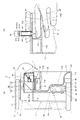
図1は、ネイルプリント装置の正面図であり、図2(a)は、ネイルプリント装置の図1におけるII−II線に沿う側断面図である。
図1及び図2(a)に示すように、このネイルプリント装置(描画装置)1は、ケース本体2と、このケース本体2に収容される装置本体10と、を備えている。なお、図1及び図2(a)において、ケース本体を二点鎖線で示している。
FIG. 1 is a front view of the nail printing apparatus, and FIG. 2A is a side sectional view of the nail printing apparatus taken along line II-II in FIG.
As shown in FIGS. 1 and 2A, the nail printing apparatus (drawing apparatus) 1 includes a case
ケース本体2の前面上部一端には、後述する描画ユニット40のペン41(筆記具)を交換するために開閉可能に構成されたペン交換用蓋部23が設けられている。ペン交換用蓋部23は、例えばヒンジ等を介して、図2(a)に示すように閉状態から開状態まで回動自在となっている。
さらに、ケース本体2の一側面(本実施形態では、図1において左側面)であって後述するペン慣書部61に対応する位置には、ペン慣書部61に載置される被描画媒体(図示せず)を入れ替え可能な媒体挿出口24が形成されている。
A
Further, a drawing medium placed on the pen custom-
ケース本体2の上面(天板)には操作部25(図5参照)が設置されている。
操作部25は、ユーザが各種入力を行う入力部である。
操作部25には、例えば、ネイルプリント装置1の電源をONする電源スイッチ釦、動作を停止させる停止スイッチ釦、爪Tに描画するデザイン画像を選択するデザイン選択釦、描画開始を指示する描画開始釦等、各種の入力を行うための図示しない操作釦が配置されている。
An operation unit 25 (see FIG. 5) is installed on the upper surface (top plate) of the
The
The
また、ケース本体2の上面(天板)のほぼ中央部には表示部26が設置されている。
表示部26は、例えば液晶ディスプレイ(LCD:Liquid Crystal Display)、有機エレクトロルミネッセンスディスプレイその他のフラットディスプレイ等で構成されている。
本実施形態において、この表示部26には、例えば、印刷指U1を撮影して得た爪画像(爪Tの画像を含む指画像)、この爪画像中に含まれる爪Tの輪郭線等の画像、爪Tに描画すべきデザイン画像を選択するためのデザイン選択画面、デザイン確認用のサムネイル画像、各種の指示を表示させる指示画面等が適宜表示される。
なお、表示部26の表面に各種の入力を行うためのタッチパネルが一体的に構成されていてもよい。
In addition, a
The
In the present embodiment, the
Note that a touch panel for performing various inputs may be integrally formed on the surface of the
装置本体10は、ほぼ箱状に形成され、ケース本体2の内部下方に設置された下部機枠11と、この下部機枠11の上方で且つケース本体2の内部上方に設置されている上部機枠12と、を備えている。
The apparatus
まず、下部機枠11について説明する。
下部機枠11は、背面板111、底板112、左右一対の側板113a,113b、X方向移動ステージ収容部114、Y方向移動ステージ収容部115及び隔壁116を有する。
側板113a,113bの下端部は、底板112の左右両端部にそれぞれ連結され、側板113a,113bが底板112に対して立てられた状態に設けられている。
図2(a)に示すように、背面板111の下部は、前方(指挿入方向手前側)に向かって2段に窪むように形成されている。背面板111の下端部は底板112の前端部に連結されており、背面板111は、底板112と側板113a,113bによって囲われた領域を前後に区切っている。
この窪んだ背面板111の後ろ側に形成される空間がX方向移動ステージ収容部114、Y方向移動ステージ収容部115(図2(a)参照)となっている。X方向移動ステージ収容部114内には、描画ユニット40が前方(指挿入方向手前側)に移動した際に描画ユニット40のX方向移動ステージ45が収容される。また、Y方向移動ステージ収容部115内には、描画ユニット40のY方向移動ステージ47が配置されている。
また、隔壁116は、下部機枠11の内部前方側の空間(背面板111、底板112及び側板113a,113bによって囲われた指挿入方向手前側の空間)を上下に区切るように下部機枠11の内側に設けられている。隔壁116はほぼ水平に設けられ、隔壁116の左右両端部が側板113a,113bにそれぞれ連結され、隔壁116の後端部が背面板111に連結されている。
First, the
The
The lower ends of the
As shown in FIG. 2A, the lower portion of the
A space formed on the back side of the recessed back
Further, the
この下部機枠11には、指固定部30が一体的に設けられている。
指固定部30は、描画を施す爪Tに対応する指(以下、これを「印刷指U1」という。)を受け入れる指受入部31と、この印刷指U1以外の指(以下、これを「非印刷指U2」という。)を退避させる指退避部32と、から構成されている。
指受入部31は、隔壁116の上側であって下部機枠11の幅方向のほぼ中央部に配置されている。また、隔壁116によって下部機枠11の下側に区分けられた空間が指退避部32を構成している。
例えば、薬指の爪Tに描画を施す場合には、指受入部31に印刷指U1としての薬指を挿入し、非印刷指U2であるその他の4指(親指、人差し指、中指、小指)を指退避部32に挿入する(図2(b)参照)。
指受入部31は、下部機枠11の前面側(印刷指挿入方向の手前側)に開口しており、下側が隔壁116の一部を構成する指載置部116a、両側が仕切り31a、奥側が仕切り31cによって区画されている。指載置部116aは、描画を施す爪Tの指(印刷指U1)をXY平面上に載置するものである。
また、指受入部31の上側は天井部31dによって区画されている。天井部31dには、指受入部31に挿入された印刷指U1の爪Tを露出させるための窓31eが形成されている。
The
The
The
For example, when drawing on the nail T of the ring finger, the ring finger as the printing finger U1 is inserted into the
The
Further, the upper side of the
また、隔壁116の上面であって下部機枠11の前面側の両側部には、下部機枠11の前面側を塞ぐ前壁31f(図1参照)が立設されている。また、隔壁116の上面には、この前壁31fの中央部寄りの端部から前記指受入部31に向けて狭窄し、印刷指U1を指受入部31内に案内する一対のガイド壁31gが立設されている。
ユーザは指受入部31に挿入した印刷指U1と指退避部32に挿入した非印刷指U2との間に隔壁116を挟むことができる。そのため、指受入部31内に挿入された印刷指U1が安定して固定される。
なお、本実施形態では、隔壁116の前端部に下方向に張り出した突出部116bが形成されている。突出部116bは、手前側に向かうにつれてその厚さが漸減し、奥側に向かうにつれて漸増するテーパー部となっていてもよいし、突出部116bの厚さが、隔壁116の奥側の窪みに対して全体が厚い構造になっていてもよい。
Further,
The user can sandwich the
In the present embodiment, a protruding
図1及び図2(a)に示すように、隔壁116の上面であって、指受入部31の横(ケース本体2の媒体挿出口24に対応する位置であり、本実施形態では、図1において左側)には、後述する描画ヘッド42による描画可能範囲内に、後述するペン41の慣らし書きをするためのペン慣書部61が設けられている。なお、ペン慣書部61は、印刷指U1が指受入部31に挿入された際の爪Tの高さとほぼ同じとなる高さに設けられていることが好ましい。
ペン慣書部61は、平板状の部分であり、前述のケース本体2の媒体挿出口24から挿入された図示しない被描画媒体が載置されるようになっている。
ペン慣書部61に載置される被描画媒体は、ペン先412の先端の描画部413を慣らすことができるものであればよく、例えば紙片であり、媒体挿出口24から交換可能となっている。
ペン慣書部61は、描画部413が乾いていたりインクの乗りが悪い等により書き始めがかすれたりするのを防止するために、爪Tに画像データによる描画を開始する前に被描画媒体の上にペン41を下ろして「○」や「∞」等の所定の図形を描画して慣らし書きを行い、ペン先412の先端の描画部413の状態を良好にするためのものである。
As shown in FIGS. 1 and 2 (a), it is the upper surface of the
The pen custom-
The drawing medium placed on the pen
In order to prevent the
また、本実施例ではゴム製のペンキャップ62がペン慣書部61の前方(指挿入方向の手前側)に設置されている。ペンキャップ62は、描画ユニット40に装着されるペン41に対応する数(本実施形態では4つ)だけ設けられており、描画ユニット40にペン41を装着後であって描画を行っていないとき(非描画時)には、ペン41はペンキャップ62に収容される。ペンキャップ62等が配置されている領域は、非描画時に、ペン41が待機しているホームスペースとなっている。
すなわち、非描画時には、ペン41をペンキャップ62の真上にペン41を移動させた後、後述するソレノイド440(図3(a)等参照)によってペン41を下降させ、ペン先412をペンキャップ62内に収容する。なお、本実施形態では後述するようにペン41のペン先412の軸線がペン41の軸部の軸線に対して、爪Tの幅方向における左右いずれか一方側に傾斜している。このため、ペンキャップ62もこれに沿う形状に形成されている。また、ペン41をペンキャップ62の設けられているホームスペースに移動させる際には、ペンキャップ62に収容可能な向きとなるように全てのペン41の向きを揃えるようになっている。
このようにペン先412をペンキャップ62内に収容することにより、非描画時におけるペン先412の描画部413の乾燥を防止することができる。なお、ペンキャップ62の形状等は図示例に限定されず、例えば、描画ユニット40に装着される全てのペン41のペン先412を受け入れることのできる長尺な溝状のペンキャップ等であってもよい。
なお、本実施形態では、このように、ペンキャップ62がペン慣書部61の傍に設けられているので、描画を開始するときには、ペン41を上昇させてすぐ傍のペン慣書部61で慣らし書きを行った後、描画を開始することができる。このため、ペン41の移動等にかかる時間を最小限に抑えることができて、迅速な描画動作を行うことができる。
Further, in this embodiment, a
That is, at the time of non-drawing, the
By accommodating the
In the present embodiment, the
描画ユニット40は、筆記具であるペン41を備える描画ヘッド42、描画ヘッド42を支持するユニット支持部材44、描画ヘッド42をX方向(図1におけるX方向、ネイルプリント装置1の左右方向)に移動させるためのX方向移動ステージ45、X方向移動モータ46、描画ヘッド42をY方向(図2(a)におけるY方向、ネイルプリント装置1の前後方向)に移動させるためのY方向移動ステージ47、Y方向移動モータ48等を備えて構成されている。
The
本実施形態において、描画ヘッド42は、それぞれ1本ずつ筆記具としてのペン(描画用具)41を保持するペンキャリッジ43を4つ備えている。
ペン41は、爪Tの表面を描画対象面とし、先端部であるペン先412の先端の描画部413(図3(a)、図3(b)、図3(c)及び図3(f)参照)が描画対象面である爪Tの表面に接触して、爪Tの表面に描画を施す筆記具である。
In the present embodiment, the drawing
The
図3(a)から図3(e)は、ペンキャリッジ43及びこれに支持されたペン41を拡大した図であり、爪Tに描画を行っているときの状態(描画状態)を示している。
図3(a)は、ペンキャリッジ43及びペン41の側面図であり、図3(b)及び(c)は、図3(a)のペンキャリッジ43及びペン41を矢視b方向から見た正面図である。図3(c)は、ペン41を図3(b)に示した状態から、ペン41のペン軸部411の軸中心を通る軸線CL周りに180度回転させたときの状態を示している。また、図3(d)は、図3(b)のペン41及びペンホルダ431を矢視d方向から見た下面図であり、図3(e)は、図3(c)のペン41及びペンホルダ431を矢視e方向から見た下面図である。また、図3(f)は、爪Tに描画を行っているときの、ペン41のペン先412の描画部413と爪Tとの接触状態を示す図である。
3A to 3E are enlarged views of the
3A is a side view of the
図3(a)、図3(b)及び図3(c)に示すように、ペンキャリッジ43に保持されるペン41は、円柱状のペン軸部411を有し、このペン軸部411の一端側にペン先412が設けられ、ペン先412の先端に描画対象面に接触する描画部413が設けられた構成を有している。ペン軸部411の内部は、各種インクを収容するインク収容部となっており、ペン先412は先端の描画部413からペン軸部411側に向かって径が次第に大きくなるテーパー形状を有し、ペン先412の側面はペン先軸線SLに対して傾斜した傾斜面となっている。
ペン軸部411の内部に収容されるインクは、粘度や色材(顔料等)の粒径(粒子の大きさ)等は特に限定されず、例えば、金銀のラメ入りのインクや白色の顔料等の各種色材を含むインク、UV硬化型のインクやジェルネイル、アンダーコート用、トップコート用やマニキュア液等を広く用いることができる。
As shown in FIG. 3A, FIG. 3B, and FIG. 3C, the
The ink accommodated in the
また、ペン軸部411の外周面には、後述するペンホルダ431の切り欠き部431a(図4(a)及び図4(b)参照)に係止される係止凸部411a(図4(a)及び図4(b)参照)が形成されている。係止凸部411aは、切り欠き部431aに係止可能なものであればよく、その形状等は特に限定されない。ペン41は、この係止凸部411aが切り欠き部431aに係止された状態においてペン先412が後述するペン先軸線SLが鉛直方向に対して右側に傾斜した状態又は左側に傾斜した状態のいずれかとなる位置に位置決めされるようになっている。
本実施形態では、後述するように、ペンホルダ431に一対の切り欠き部431aが形成されており、係止凸部411aは、例えば、この一対の切り欠き部431aに対応する2箇所に設けられている。なお、係止凸部411aがいずれかの切り欠き部431aに係止されれば、ペン41を位置決めすることができるため、係止凸部411aは、切り欠き部431aに対応してそれぞれ設けられていなくてもよく、1箇所のみに設けられていてもよい。
また、係止凸部411aは切り欠き部431aに係止可能なものであればよく、その形状等は図示例に限定されない。
Further, on the outer peripheral surface of the
In this embodiment, as will be described later, a pair of
Moreover, the latching
ペン41は、ペン先412の先端の描画部413が爪Tの表面に押し当てられることでペン軸部411内に収容されているインクを爪Tの表面に塗布して描画する、例えば描画部413がボールペンタイプとなったペンである。なお、ペン41は、ボールペンタイプのものに限定されず、例えば描画部413をなすフェルト状の部材にインクを染み込ませて描画するサインペンタイプや、描画部413をなす束ねた毛にインクを染み込ませて描画する筆ペンタイプのもの等であってもよい。また、描画部413の太さや形状も各種のものを用意することができる。
各ペンキャリッジ43に保持されるペン41は、同じタイプの描画部413を有するペンでもよいし、異なるタイプの描画部413を有するペンであってもよい。
The
The
筆記具であるペン41は、図3(b)から図3(e)に示すように、ペン先412先端の描画部413からペン先412の中心を通るペン先軸線SLが、ペン軸部411の軸中心を通るペン軸軸線CLに対して所定の角度θだけ傾斜した形状を有している。ここで、ペン軸軸線CLは、ペン41がペンキャリッジ43のペンホルダ431に挿入されて保持されている状態で鉛直方向(本実施形態では、爪Tが配置されている指載置部116aの表面に対して垂直方向)となっている。
ペン41は、ペン先412のペン先軸線SLが、指載置部116aに載置された爪Tの幅方向に沿って、鉛直方向に対して角度θだけ右側に傾斜した状態(図3(c)に示す状態、以下、第1傾斜状態とする)又は角度θだけ左側に傾斜した状態(図3(b)に示す状態、以下、第2傾斜状態とする)の何れかに設定され、初期状態として、第1傾斜状態又は第2傾斜状態のいずれかの状態になるようにペンキャリッジ43に装着される。そして、ペン41は、第1傾斜状態になっているとき、ペン41を、ペン軸軸線CLを中心として、ペン軸軸線CL周りに180度回転させることにより第2傾斜状態に設定され、第2傾斜状態になっているとき、ペン41を、ペン軸軸線CLを中心として、ペン軸軸線CL周りに180度回転させることにより第1傾斜状態に設定される。
このペン先412のペン先軸線SLの傾斜方向は、描画する爪Tの湾曲形状に応じて設定され、図3(f)に示すように、爪Tの右側端部近傍に描画する際には、ペン先412のペン先軸線SLが左側に傾斜した第2傾斜状態に設定され、爪Tの左側端部近傍に描画する際には、ペン先412のペン先軸線SLが右側に傾斜した第1傾斜状態に設定される。これにより、ペン先412の描画部413が湾曲した爪Tの端部にも当接し易くなり、爪Tの端部で描画する線がかすれたり、途切れたりすることを抑制することができる。
図3(b)及び図3(c)に示すLはペン先412の長さを示し、Dはペン先412の先端の描画部413の、ペン先軸線SLが傾斜していない場合に対するずれ量を示している。すなわち、ずれ量Dは、ペン軸軸線CLと基準となる水平面(すなわち、例えば爪Tが配置されている指載置部116aの表面)との交点を基点Pとしたとき、基点Pと描画部413との間の距離である。ここで、Lが5mmであり、ペン先軸線SLのペン軸軸線CL(鉛直線)に対する傾斜角度θが20度である場合、ずれ量Dは1.82mmとなる。
図4(a)及び図4(b)は、本実施形態において、ペン41がペンホルダ431内で上方に持ち上げられて、ペン41がペンホルダ431内で回転可能になっている状態をネイルプリント装置1の手前側(図2(a)において右側)から見た図であり、図4(b)は、図4(a)の状態からペン41を、ペン軸軸線CLを中心として、ペン軸軸線CL周りに180度回転させたときの状態を示している。図4(a)及び図4(b)に示す状態からペン41が下方に下りたとき、係止凸部411aが切り欠き部431aに係止される。
ペン先412の向きは後述する記憶部82のペン先方向記憶領域824に記憶される。
As shown in FIGS. 3 (b) to 3 (e), the
In the
The inclination direction of the nib axis SL of the
3B and 3C, L indicates the length of the
4A and 4B show the state in which the
The direction of the
ペン軸部411の他端側(すなわち、ペン先412とは反対側)には、ペン軸部411よりも外側に張り出した鍔部413が形成された蓋部414が取り付けられている。ペン軸部411及び蓋部414を形成する材料は特に限定されないが、ペン41を量産するために適した樹脂等で形成されていることが好ましい。
本実施形態において、蓋部414の上部には、手やピンセット等でつまみ易いようにつまみ部415が設けられており、さらに、このつまみ部415には、例えば、磁石に吸着するように小さな鉄片416が埋設、貼着等により設けられている。
ペン41は後述するようにペンキャリッジ43のペン保持部437d及びペンホルダ431に上方から挿通するだけで保持されているため、ケース本体2に設けられているペン交換用蓋部23を開けて、例えば手やピンセットでつまみ部415を摘む、若しくは、図示しない棒状部材の先に磁石を取り付けたものをつまみ部415に近づけて鉄片416を磁石に吸着させて引き上げる等の手法により、簡易に交換が可能である。このため、ユーザは、各ペンキャリッジ43に装着するペン41を、描画したいネイルデザインに応じてペン先412の種類やインクの種類の異なるペン41に適宜入れ替えることで、幅広いネイルデザインを実現することができる。
On the other end side of the pen shaft portion 411 (that is, the side opposite to the pen tip 412), a
In the present embodiment, a
As will be described later, since the
本実施形態では、図3(a)、図3(b)及び図3(c)に示すように、ペン41の上部(本実施形態では、鍔部413と摘み部415との間)に、回転用歯車417が設けられている。
回転用歯車417の外径は、ペン41において最も外径の大きな部分(本実施形態では鍔部413)の外径と同じかこれよりも大きく形成されている。
In this embodiment, as shown in FIG. 3A, FIG. 3B, and FIG. 3C, in the upper part of the pen 41 (in this embodiment, between the
The outer diameter of the
図4(a)及び図4(b)に示すように、ペン41の近傍には、回転用歯車417を回転させるためのペン回転モータ443が設けられている。
ペン回転モータ443は、ペン41を、当該ペン41のペン軸部411の軸線を中心として、軸回り(ペン41又はこれを保持するペンホルダ431の軸回り)に180度回転させることで、先端部であるペン先412のペン先軸線SLの傾斜方向を反転させる駆動部を構成し、傾斜方向切替部として機能する。
すなわち、ペン41が、第1傾斜状態(ペン41の先端部であるペン先412のペン先軸線SLが鉛直方向に対して右側に傾斜した状態、図4(b)参照)となっている場合に、ペン回転モータ443を動作させてペン41を当該ペン41の軸回りに180度回転させると、ペン先412の向きが反転し、ペン先軸線SLが鉛直方向に対して左側に傾斜した第2傾斜状態(図4(a)参照)となる。
As shown in FIGS. 4A and 4B, a
The
That is, when the
ペン回転モータ443は、後述する描画制御部815(図5参照)によって制御されるようになっている。
ペン回転モータ443としては、例えば、ステッピングモータ等、描画制御部815により回転量を制御可能な各種のモータを適用することができる。
ペン回転モータ443には、軸444を介して回転用歯車417と噛み合うモータ側歯車445が設けられている。
The
As the
The
図4(d)は、本実施形態のモータ側歯車445の平面図である。
図4(d)に示すように、本実施形態のモータ側歯車445の外周面には、回転用歯車417と噛み合うギア部445aと、ギア(歯)が形成されていない離脱部445bとが形成されている。
ギア部445aの長さGLは、回転用歯車417の外周の長さのほぼ1/2の長さとなっており、離脱部445bは、当該ギア部445aの両側に配置されている。
これにより、モータ側歯車445が回転用歯車417と噛み合った状態で回転した場合、ペン41がその軸回りに約180度回転したところで、ギア(歯)が形成されていない離脱部445bが回転用歯車417との対向位置に配置される。この状態においては、回転用歯車417とモータ側歯車445とのギア(歯)同士の嵌合が解除され、ペン41の回転が停止する。
また、この離脱部445bが回転用歯車417との対向位置に配置された状態では回転用歯車417がモータ側歯車445に引っ掛からないため、ペン41を上下に移動させることができる。これにより、ペン41を交換する際等に、円滑にペン41の着脱を行うことが可能となる。
本実施形態では、離脱部445bが回転用歯車417との対向位置に配置された状態において、前述の係止凸部411aが後述するペンホルダ431の切り欠き部431aに対応する位置に配置される(図4(a)及び図4(b)参照)。離脱部445bとの対向位置において回転用歯車417とモータ側歯車445との嵌合が解除されると、ペン41は下方向に移動可能となり、ペン41が下方向に移動したとき、係止凸部411aが切り欠き部431aに係止されるようになっている。
FIG. 4D is a plan view of the
As shown in FIG. 4D, on the outer peripheral surface of the
The length GL of the
As a result, when the
Further, in a state in which the detaching
In the present embodiment, in the state where the
各ペンキャリッジ43には、ペン41をほぼ垂直に保持するペンホルダ431と、ペン41を上下移動させるためのペン上下機構432とが設けられている。
ペンホルダ431は、上下に開口し、ペン41を保持する筒状の形状を有し、内部にペン先412及びペン軸部411が挿通される。
図4(c)は、本実施形態におけるペンホルダ431の一例を示した斜視図である。
図4(c)に示すように、ペンホルダ(描画用具ホルダ)431の上部の開口部には、ペン軸部411に設けられた係止凸部411aが係止される一対の切り欠き部431aが形成されている。
切り欠き部431aは、開口側の端部が最も幅が広く、下方に行くに従って徐々に幅が狭くなるテーパー状となっており、切り欠き部431aの下端部は係止凸部411aの幅よりも僅かに幅の広い溝状部となっている。このように切り欠き部431aの形状がテーパー状となっていることにより、ペン41を切り欠き部431aの開口側の端部の幅内で、幅の中心よりずれた位置からペンホルダ431に落とし込むようになった場合でも、係止凸部411aがテーパー状の傾斜面に案内されて切り欠き部431aの下端部の溝状部に嵌り、ペン41が適切な位置に位置決めされる。これにより、モータ側歯車445によるペン41の回転角度は正確に180度でなくてもよく、切り欠き部431aの開口側のテーパー状の端部の幅内に入る角度範囲内であればよい。
これにより、係止凸部411aが切り欠き部431aの下端部の溝状部に嵌った状態において、ペン41は、ペン先412のペン先軸線SLが鉛直方向に対して右側に傾斜した第1傾斜状態、又は、ペン先412のペン先軸線SLが鉛直方向に対して左側に傾斜した第2傾斜状態のいずれかとなるように位置決めされる。
Each
The
FIG. 4C is a perspective view showing an example of the
As shown in FIG. 4C, a pair of
The
Accordingly, in the state where the locking
図3(a)に示すように、ペン上下機構432は、プランジャ434とコイル部435で構成されるソレノイド440と、ソレノイド440のプランジャ434の移動端側に取り付けられたピン436と、このピン436を介してプランジャ434と連結されているペン上下レバー437と、ペン上下レバー437が上昇しすぎるのを抑制するストッパ438と、を備えている。
As shown in FIG. 3A, the pen up-and-
ソレノイド440は、銅線等が巻回されたコイル部435の中で可動式のプランジャ434がピストンのように往復運動をする仕組みとなっている。プランジャ434は、ばね433によって前方(図2(a)、図3(a)における右側方向)に付勢されており、ソレノイド440は、このばね433の付勢力に抗してプランジャ434を後方(図2(a)、図3(a)における左側方向)に吸引するプル型のソレノイドである。なお、ソレノイド440は、プル型に限定されず、プッシュ型に構成されたものでもよい。
The
ペン上下レバー437は、図3(a)に示すように、短アーム437aと長アーム437bとがほぼ直角に交わるL字状の部材であり、短アーム437aの先端側にピン436に係止される長孔437cが形成されている。また、長アーム437bの先端側には、ペン41が挿通されるペン保持部437dが設けられている。ペン保持部437dは、ペン41のペン軸部411及びペン先412の径よりも大きく、ペン41の鍔部413の径よりも小さい内径を有するリング状に形成されており、ペン軸部411及びペン先412を挿通させるとともに鍔部413を下側から支持するように係止している。
ペン上下レバー437における短アーム437aと長アーム437bとの交点には、ペンキャリッジ43側から支軸439が挿通されている。
As shown in FIG. 3A, the pen up / down
A
本実施形態において、ソレノイド440が駆動されている状態では、図3(a)に示すように、ばね433の付勢力に抗してプランジャ434が後方に引かれた状態となり、プランジャ434のピン436に係止されているペン上下レバー437は長アーム437bがほぼ水平となる位置で保持される。この状態において、ペン41は、ペン先412がペンキャリッジ43のペンホルダ431よりも下方に下りた状態となり、ペン先412の先端の描画部413が爪Tの表面や被描画媒体と接触可能な描画状態となる。一方、ソレノイド440が開放された状態では、ばね433の付勢力によってプランジャ434が前方に突出する。このとき、プランジャ434のピン436に係止されているペン上下レバー437は支軸439を支点として上方向(反時計方向)に回動し、長アーム437bがストッパ438に当接して止まる。これにより、ペン41の鍔部413が、ペン上下レバー437によって上方向に跳ね上げられる(図2(a)参照)。この状態において、ペン41は、ペン先412がペンキャリッジ43のペンホルダ431内で上方に上がった状態となり、ペン先412の先端の描画部413が爪Tの表面や被描画媒体と接触しない非描画状態となる。
このように、ソレノイド440のプランジャ434を前後移動させる力は、支軸439及びこれを支点として回動するペン上下レバー437によってペン41を上下移動させる力に変換される。
In this embodiment, when the
As described above, the force for moving the
なお、ペン41は、ペンキャリッジ43のペンホルダ431に挿通されて保持されているのみであり、ペン上下レバー437等に固定されていないため、自重によって下方に付勢されている。これにより、ペン41は、鍔部413がペン保持部437dの上面に接触する位置まで、ペンホルダ431に沿って自由に下降できるとともに、描画状態でペン先412の描画部413が爪Tの表面や被描画媒体に突き当たると、ペン先412の描画部413がペン41の自重によって爪Tの表面や被描画媒体に押し当てられ、爪Tの表面形状(表面の起伏等)に追従して、印刷指U1が載置されているXY平面に直交するZ方向(すなわち上下方向)に自由に移動するように構成されている。
ペン41の重量は数グラム〜数十グラムと極めて軽量であるため、ペン先412の描画部413が爪Tに突き当たってもユーザが痛みを感じることはなく、また自重によりペン41の筆圧が確保されるため、爪Tの上等にネイルデザインを描くことができる。
Note that the
Since the weight of the
本実施形態では、このペン上下機構432を構成する部材のうち、支軸439及びストッパ438は、ステンレス等の金属で形成されており、それ以外の部材は、樹脂等の軽量で磁石に反応しない材料で形成されている。なお、ペン上下機構432を構成する部材の材料は、ここに例示したものに限定されない。
また、本実施形態では、ペン41を上下させるためのアクチュエータとしてソレノイド440を用いているが、ペン41を上下させるためのアクチュエータは、ソレノイド440に限定されない。ペン41は軽量であるため、ソレノイドの他、各種小型の駆動装置によりペン41を上下させるためのアクチュエータを構成することができる。
In the present embodiment, among the members constituting the pen up-and-
In this embodiment, the
描画ヘッド42を支持するユニット支持部材44は、X方向移動ステージ45に取り付けられたX方向移動部451に固定されている。X方向移動部451は、X方向移動モータ46の駆動によりX方向移動ステージ45上を図示しないガイドに沿ってX方向に移動するようになっており、これにより、描画ヘッド42がX方向(図1におけるX方向、ネイルプリント装置1の左右方向)に移動するようになっている。
また、X方向移動ステージ45は、Y方向移動ステージ47のY方向移動部471に固定されている。Y方向移動部471は、Y方向移動モータ48の駆動によりY方向移動ステージ47上を図示しないガイドに沿ってY方向に移動するようになっており、これにより、描画ヘッド42がY方向(図2(a)におけるY方向、ネイルプリント装置1の前後方向)に移動するようになっている。
なお、本実施形態において、X方向移動ステージ45及びY方向移動ステージ47は、X方向移動モータ46、Y方向移動モータ48と、図示しないボールネジ及びガイドとを組み合わせることで構成されている。本実施形態のX方向移動モータ46及びY方向移動モータ48としては、1パルス送られるごとに所定量ずつ移動するステップモータが適用される。
本実施形態では、X方向移動モータ46及びY方向移動モータ48等により、爪Tに描画を施すペン41を備える描画ヘッド42をX方向及びY方向に駆動するヘッド駆動部49(図5参照)が構成されている。
The
The X
In this embodiment, the X
In the present embodiment, a
描画ユニット40におけるペン41を上下移動させるためのソレノイド440、ペン回転モータ443、X方向移動モータ46、Y方向移動モータ48は、後述する制御装置80の描画制御部815(図5参照)に接続され、該描画制御部815によって制御されるようになっている。
A
図1及び図2(a)に示すように、撮影部50は、上部機枠12に設けられている。
すなわち、上部機枠12には基板13が設置されており、この基板13の中央部下面には、撮影部50の撮像装置としてのカメラ51が2つ設置されている。
カメラ51は、例えば、200万画素程度以上の画素を有する固体撮像素子とレンズ等を備えて構成された小型カメラであることが好ましい。
カメラ51は、指受入部31内に挿入されている印刷指U1の爪Tを撮影して、印刷指U1の爪Tの画像である爪画像(爪Tの画像を含む指画像)を得るものである。
本実施形態では、2つのカメラ51は、指受入部31に挿入されている印刷指U1の爪Tの幅方向にほぼ並んで設けられている。2つのカメラ51のうち、一方のカメラ51は、指受入部31の底面に対向して設けられており、爪Tを真上から撮影するものである。また、他方のカメラ51は、指受入部31の底面に対して僅かに傾けて配置されており、爪Tを斜め上方向から撮影するものである。
また、基板13には、カメラ51を囲むように白色LED等の照明灯(照明装置)52が設置されている。照明灯52は、カメラ51による撮影の際に、印刷指U1の爪Tを照明するものである。撮影部50は、このカメラ51及び照明灯52を備えて構成されている。
この撮影部50は、後述する制御装置80の撮影制御部811(図5参照)に接続され、該撮影制御部811によって制御されるようになっている。
撮影部50によって撮影された画像の画像データは、後述する記憶部82の爪画像記憶領域821に記憶される。
As shown in FIGS. 1 and 2A, the photographing
That is, the
The
The
In the present embodiment, the two
An illumination lamp (illumination device) 52 such as a white LED is installed on the
The photographing
Image data of an image photographed by the photographing
本実施形態では、撮像装置としての2つのカメラ51によって少なくとも2つの異なった位置・角度から爪Tを撮影することができ、少なくとも2枚の爪画像が取得される。
そして、これらの爪画像に基づいて、後述する爪情報検出部812が、爪Tの輪郭(爪Tの形状)の他、爪Tの表面の、XY平面に対する傾斜角度(以下「爪Tの傾斜角度」又は「爪曲率」という。)や爪Tの垂直位置等の爪情報を検出できるようになっている。
In this embodiment, the nail | Tail T can be image | photographed from at least 2 different positions and angles with the two
Then, based on these nail images, a nail information detecting unit 812 (to be described later) in addition to the contour of the nail T (the shape of the nail T), the inclination angle of the surface of the nail T with respect to the XY plane (hereinafter referred to as “the inclination of the nail T”). Nail information such as “angle” or “nail curvature”) and the vertical position of the nail T can be detected.
また、制御装置80は、例えば上部機枠12に配置された基板13等に設置されている。
図5は、本実施形態における制御構成を示す要部ブロック図である。
制御装置80は、図5に示すように、図示しないCPU(Central Processing Unit)により構成される制御部81と、ROM(Read Only Memory)及びRAM(Random Access Memory)等(いずれも図示せず)で構成される記憶部82とを備えるコンピュータである。
Further, the
FIG. 5 is a principal block diagram showing a control configuration in the present embodiment.
As shown in FIG. 5, the
記憶部82には、ネイルプリント装置1を動作させるための各種プログラムや各種データ等が格納されている。
具体的には、記憶部82のROMには、爪画像から爪Tの形状等の爪情報を検出するための爪情報検出プログラム、描画データを生成するための描画データ生成プログラム、描画処理を行うための描画プログラム等の各種プログラムが格納されており、これらのプログラムが制御装置80によって実行されることによって、ネイルプリント装置1の各部が統括制御されるようになっている。
また、記憶部82には、撮影部50によって取得されたユーザの印刷指U1の爪Tの爪画像を記憶する爪画像記憶領域821、爪情報検出部812によって検出された爪情報が記憶される爪情報記憶領域822、及び爪Tに描画されるネイルデザインの画像データを記憶するネイルデザイン記憶領域823が設けられている。
本実施形態では、前述のように、初期状態としてペン41のペン先412のペン先軸線SLが右側に傾斜している第1傾斜状態となっている。このため、ネイルデザイン記憶領域823に記憶されているネイルデザインの画像データも、第1傾斜状態のペン先412によって描画した際に正しく描画されるように構成されている。
The
Specifically, the ROM of the
Further, the
In the present embodiment, as described above, the pen tip axis SL of the
さらに、本実施形態の記憶部82には、ペン先方向記憶領域824、位置補正値記憶領域825が設けられている。
ペン先方向記憶領域824は、ペン41のペン先412の向き(方向)を記憶しているものである。
本実施形態では、前述のように、ペン41は、先端部であるペン先412のペン先軸線SLが、鉛直方向に対して右側に傾斜した第1傾斜状態と、先端部であるペン先412のペン先軸線SLが、鉛直方向に対して左側に傾斜した第2傾斜状態とを取り得るようになっており、随時、そのペン先412のペン先軸線SLの傾斜方向がペン先方向記憶領域824に記憶されるようになっている。
後述するように、描画制御部815は、記憶部82のペン先方向記憶領域824にされているペン先412のペン先軸線の傾斜方向を参照しつつ、適宜ペン回転モータ443の動作を制御する。
Further, the
The pen tip
In the present embodiment, as described above, in the
As will be described later, the
位置補正値記憶領域825は、ペン先412のペン先軸線SLの傾斜方向に対応して、ペン41による描画位置の補正を行うための補正値を記憶するものである。
ペン41が、前述のように、ペン先412の長さLが5mmであり、ペン先軸線SLのペン軸軸線CL(鉛直線)に対する傾斜角度θが20度であるとき、ペン先412の描画部413の基点Pからのずれ量は1.82mmであるから、ペン先412をペン先軸線SLが右側に傾斜した第1傾斜状態から左側に傾斜した第2傾斜状態に変えたときの描画部413の移動距離は3.64mm(=3640μm)となる。このため、本実施形態において、ペン先412のペン先軸線SLが右側に傾斜している第1傾斜状態を基準としてネイルデザインの画像データが用意されている場合には、ペン先412をペン先軸線SLが左側に傾斜した第2傾斜状態にしたときには、描画時のペン先412の描画部413の位置を、第1傾斜状態のときの位置と同じにするように、x軸方向に3.64mm(=3640μm)だけずらすように補正する。位置補正値記憶領域825には、この補正値(3640μm)が記憶される。
The position correction
As described above, when the
制御部81は、機能的に見た場合、撮影制御部811、爪情報検出部812、描画データ生成部813、表示制御部814、描画制御部815等を備えている。これら撮影制御部811、爪情報検出部812、描画データ生成部813、表示制御部814、描画制御部815等としての機能は、制御部81のCPUと記憶部82のROMに記憶されたプログラムとの共働によって実現される。
When viewed functionally, the
撮影制御部811は、撮影部50のカメラ51及び照明灯52を制御してカメラ51により、指受入部31に挿入された印刷指U1の爪Tの画像を含む指の画像(以下「爪画像」という。)を撮影させるものである。
本実施形態では、撮影制御部811は、2つのカメラ51によって異なる位置・角度(例えば、爪Tの真上と爪Tの斜め上方等)から少なくとも2枚の爪画像を取得させる。
撮影部50により取得された爪画像の画像データは、記憶部82に記憶されてもよい。
The
In the present embodiment, the
The image data of the nail image acquired by the
爪情報検出部812は、カメラ51によって撮影された指受入部31に挿入された印刷指U1の爪Tの画像に基づいて、印刷指U1の爪Tについての爪情報を検出するものである。
ここで、爪情報とは、例えば、爪Tの輪郭(爪形状、爪Tの水平位置)、爪Tの表面の、XY平面に対する傾斜角度(爪Tの傾斜角度、爪曲率)、爪Tの高さ(爪Tの垂直方向の位置、以下「爪Tの垂直位置」又は単に「爪Tの位置」ともいう。)である。なお、爪Tの傾斜角度(爪曲率)とは、爪Tの幅方向における水平面(すなわち、印刷指U1が載置されている指載置部116aのXY平面)に対する角度をいう。
The nail
Here, the nail information includes, for example, the contour of the nail T (nail shape, horizontal position of the nail T), the inclination angle of the surface of the nail T with respect to the XY plane (inclination angle of the nail T, nail curvature), Height (position of nail T in the vertical direction, hereinafter also referred to as “vertical position of nail T” or simply “position of nail T”). Note that the inclination angle (nail curvature) of the nail T refers to an angle with respect to the horizontal plane in the width direction of the nail T (that is, the XY plane of the
具体的には、爪情報検出部812は、カメラ51により取得された印刷指U1の爪Tの爪画像から、爪Tの輪郭(形状や大きさ)、位置を検出し、この輪郭をx,y座標等で表される情報として取得する。爪情報検出部812は、例えば、カメラ51により取得された印刷指U1の爪Tの爪画像から爪Tとそれ以外の指部分との色の違い等に基づいて爪Tの輪郭(形状)を検出するものである。なお、爪情報検出部812が爪Tの輪郭(形状)を検出する手法は特に限定されず、ここに挙げたものに限られない。
また、爪情報検出部812は、2つのカメラ51によって撮影された少なくとも2つの爪画像に基づいて、爪Tについて爪Tの傾斜角度(爪曲率)を検出する傾斜角度検出部として機能する。
爪情報検出部812は、例えば2つのカメラ51によって異なる位置・角度(例えば、爪Tの真上と爪Tの斜め上方等)から撮影された2つの爪画像からユーザの爪Tについて傾斜角度(爪曲率)を検出する。
なお、爪情報検出部812は、爪画像に基づいて、少なくとも爪Tの輪郭(爪形状)を検出すればよく、上記爪情報の全てを取得しなくてもよい。
Specifically, the nail
The nail
For example, the nail
Note that the nail
描画データ生成部813は、爪情報検出部812により検出された爪情報に基づいて、描画ヘッド42により印刷指U1の爪Tに描画される描画用のデータを生成する。
具体的には、描画データ生成部813は、爪情報検出部812により検出された爪Tの形状等に基づいてネイルデザインの画像データを拡大、縮小、切出し等による合せ込み処理を行い、爪Tに描画を施すためのデータを生成する。なお、爪情報検出部812が爪Tの傾斜角度(爪曲率)についても爪情報として取得している場合には、描画データ生成部813は、爪Tの傾斜角度(爪曲率)に応じて、ネイルデザインの画像データの曲面補正を行う。
The drawing
Specifically, the drawing
表示制御部814は、表示部26を制御して表示部26に各種の表示画面を表示させるものである。本実施形態では、表示制御部814は、例えばネイルデザインの選択画面やデザイン確認用のサムネイル画像、爪Tを含む印刷指U1を撮影した爪画像等、各種の画面を表示部26に表示させるようになっている。
The
描画制御部815は、描画データ生成部813によって生成された描画データを描画ユニット40に出力し、爪Tに対してこの描画データにしたがった描画を施すように描画ユニット40のソレノイド440、ペン回転モータ443、X方向移動モータ46、Y方向移動モータ48を制御する制御部である。
本実施形態では、描画制御部815は、爪Tの表面の幅方向(図3(f)において左右方向)における中央部(図3(f)において一点鎖線で示した中心線部分)を切替位置として、ペン先412を、ペン先軸線SLが右側に傾斜した第1傾斜状態から左側に傾斜した第2傾斜状態に切り替える、又は、第2傾斜状態から第1傾斜状態に切り替える。
具体的には、描画制御部815は、描画対象面の描画を施す位置(描画位置)を常に判断し、描画位置が爪Tの表面の幅方向(図3(f)において左右方向)における中央部よりも右側である場合には、ペン先412をペン先軸線SLが鉛直方向に対して左側に傾斜した第2傾斜状態に設定し、中央部よりも左側である場合には、ペン先412をペン先軸線SLが鉛直方向に対して右側に傾斜した第2傾斜状態に設定するように、ペン回転モータ443を制御して、適宜ペン先412のペン先軸線SLの傾斜方向を切り替える。
また、本実施形態では、描画データ生成部813は、ペン41のペン先412のペン先軸線SLの傾斜方向が第1傾斜状態から第2傾斜状態に切り替えられたとき、位置補正値記憶領域825に記憶されている補正値によってペン先412の位置を補正する。
The
In the present embodiment, the
Specifically, the
In the present embodiment, the drawing
なお、一繋がりのデザインパーツ(例えば、花柄や星柄等の絵柄)がこの切替位置に跨って存在しているときは、当該デザインパーツ(絵柄)の描画が完了するまでペン先412のペン先軸線SLの傾斜方向を切り替えないように制御することが好ましい。ペン先412のペン先軸線SLの傾斜方向が切り替わると、インクの塗布方向が変わることでその部分で塗布した線の形状が乱れることがある。このため、一繋がりのデザインパーツ(絵柄)の途中ではペン先412のペン先軸線SLの傾斜方向を切り替えないとすることにより、仕上がりの美しいネイルプリントを実現することができる。
When a series of design parts (for example, a pattern such as a flower pattern or a star pattern) is present across the switching position, the pen of the
次に、図6等を参照し、本実施形態におけるネイルプリント装置1の動作及び描画制御方法について説明する。 Next, the operation of the nail print apparatus 1 and the drawing control method in the present embodiment will be described with reference to FIG.
このネイルプリント装置1により描画を行う場合、ユーザはまず、電源スイッチを入れて制御装置80を起動させる。
表示制御部814は、表示部26にデザイン選択画面を表示させる。ユーザは操作部25の操作釦等を操作して、デザイン選択画面に表示された複数のネイルデザインの中から所望のネイルデザインを選択し、これにより、操作部25から選択指示信号が出力されて爪Tに描画すべきネイルデザインが選択される。
ネイルデザインが選択されると、制御部81は、当該選択されたネイルデザインを描画するのに必要なペン41を描画ヘッド42の所定のペンキャリッジ43にセットするよう促す指示画面を表示部26に表示させる。例えば、赤インク、ラメ入り金インクが必要であるときは、どのペンキャリッジ43にどのインクのペン41を装着すべきかを表示部26において指示する。ユーザは表示画面に表示された指示にしたがって、所定のペンキャリッジ43に所定の種類のペン41をセットする。なお、ユーザがあえて指示と異なるペン41をセットして、好みの色や質感のネイルデザインを実現するようにしてもよい。
なお、ペンキャリッジ43にどの種類のペン41がセットされているかをバーコード等により制御部81が読み取ることができるように構成してもよく、この場合には、ペンキャリッジ43にセットされているペン41によって描画できるネイルデザインを表示部26のデザイン選択画面を表示させ、ユーザにその中からネイルデザインを選択させるようにしてもよい。
次に、制御部81は、印刷指U1を指受入部31に挿入するよう促す指示画面を表示部26に表示させる。ユーザは、この指示に従って印刷指U1を指受入部31に挿入し、非印刷指U2を指退避部32に挿入して、印刷指U1を固定した上で、描画スイッチを操作する。
例えば、図2(b)では、左手の薬指が印刷指U1として指受入部31に挿入され、その他の指が非印刷指U2として指退避部32に挿入されている例を示している。
When drawing with the nail printing apparatus 1, the user first turns on the power switch to activate the
The
When the nail design is selected, the
It should be noted that the
Next, the
For example, FIG. 2B shows an example in which the ring finger of the left hand is inserted into the
描画スイッチから描画開始指示が入力されると、描画動作を開始する前に、まず撮影制御部811が撮影部50を制御して、照明灯52により印刷指U1を照明しながらカメラ51により印刷指U1を撮影させる。これにより、指受入部31に挿入された印刷指U1の爪Tの画像(爪画像)が、撮影部50によって取得される。
次に、図6に示すように、爪情報検出部812は、爪画像に基づいて爪Tの輪郭(爪形状)等の爪情報を検出する(ステップS1)。
When a drawing start instruction is input from the drawing switch, before the drawing operation is started, the
Next, as illustrated in FIG. 6, the nail
爪情報検出部812により爪Tの輪郭(爪形状)等の爪情報が検出されると、これらの爪情報に基づいて、描画データ生成部813が、ネイルデザインの画像データの爪Tへの合せ込み処理を行う。また、描画データ生成部813は、これら爪情報に基づいて、適宜ネイルデザインの画像データにつき曲面補正等を行う。これにより描画データが生成される(ステップS2)。
When the nail information such as the contour (nail shape) of the nail T is detected by the nail
また、描画制御部815は、爪Tへの描画開始前に、描画ユニット40をペン慣書部61に移動させて、ペン41を保持するペンキャリッジ43のソレノイド440を駆動させ、ペン41を描画可能状態とする。そして、被描画媒体に「○」や「∞」等の所定の図形を描く慣らし書きを行う。なお、慣らし書きは、選択されたネイルデザインを描画するのに必要なペン41についてのみ行ってもよいし、全てのペン41について行ってもよい。
描画データが生成され、慣らし書きも完了すると、描画制御部815は、描画領域が爪Tの幅方向(図3(f)における左右方向)の中央部よりも左側であるか否かを判断する(ステップS3)。描画領域が爪Tの幅方向における左側であると判断すると(ステップS3;YES)、次にペン先412のペン先軸線SLが鉛直方向に対して右側に傾斜した第1傾斜状態であるか否かを判断する(ステップS4)。そして、ペン先412のペン先軸線SLが第1傾斜状態でないと判断すると(ステップS4;NO)、ペン回転モータ443を動作させて、ペン先412のペン先軸線SLを第1傾斜状態に設定する(ステップS5)。
他方、描画領域が爪Tの幅方向における右側であると判断すると(ステップS3;NO)、次にペン先412のペン先軸線SLが鉛直方向に対して左側に傾斜した第2傾斜状態であるか否かを判断する(ステップS6)。そして、ペン先412のペン先軸線SLが第2傾斜状態でないと判断すると(ステップS6;NO)、ペン回転モータ443を動作させて、ペン先412のペン先軸線SLを第2傾斜状態に設定する(ステップS7)。そして、記憶部82の位置補正値記憶領域825から位置補正値を読み込み、これに応じてペン先412の位置を補正する(ステップS8)。
描画領域が爪Tの幅方向における左側であり(ステップS3;YES)、ペン先412のペン先軸線SLが第1傾斜状態であると判断した場合(ステップS4;YES)及びペン先412のペン先軸線SLが第2傾斜状態であって第1傾斜状態に設定した場合(ステップS5)と、描画領域が爪Tの幅方向における右側であり(ステップS3;NO)、ペン先412のペン先軸線SLが第2傾斜状態であると判断した場合(ステップS4;YES)及びペン先412のペン先軸線SLが第1傾斜状態であって第2傾斜状態に設定し、ペン位置を補正した場合(ステップS8)には、描画制御部815は、描画ユニット40による描画を開始させる(ステップS9)。描画動作中、描画制御部815は、当該爪Tについての描画動作が終了したか否かを随時判断し(ステップS10)、描画動作が終了していない場合(ステップS10;NO)には、終了するまでステップS3に戻って上記の処理を繰り返す。また、描画動作が終了したと判断すると(ステップS10;YES)、描画処理を終了する。
Further, the
When the drawing data is generated and the running-in is completed, the
On the other hand, if it is determined that the drawing area is the right side in the width direction of the nail T (step S3; NO), then the pen tip axis SL of the
When the drawing area is on the left side in the width direction of the nail T (step S3; YES), the pen tip axis SL of the
以上のように、本実施形態のネイルプリント装置1によれば、爪Tの表面の少なくとも右側端部に描画する際には、少なくともペン41の先端部であるペン先412が、ペン先軸線SLが鉛直方向に対して左側に傾斜した第2傾斜状態で描画を行い、爪Tの表面の少なくとも左側端部に描画する際には、少なくともペン41の先端部であるペン先412が、ペン先軸線SLが鉛直方向に対して右側に傾斜した第1傾斜状態で描画を行うように、ペン41のペン先412のペン先軸線SLの傾斜方向及びペン41による描画動作を制御する。このため、幅方向である左右方向に沿って中央部が両端側より盛り上がった湾曲形状を有する爪Tの表面に描画を施す場合でも、端部まで線がかすれたり途切れたりすることがなく、高精細なネイルプリントを施すことができる。
また、本実施形態では、傾斜方向切替部であるペン回転モータ443によりペン41を、当該ペン41の軸回りに180度回転させることでペン先412の向きを反転させる。このため、比較的簡易な機構で、端部まで美しい描画を実現することができる。
また、本実施形態の描画制御部815は、爪Tの表面の幅方向における中央部を切替位置として、ペン41の先端部であるペン先412のペン先軸線SLの傾斜方向を切り替える。このため、比較的簡易な制御により、高精細なネイルプリントを実現することができる。
As described above, according to the nail print apparatus 1 of the present embodiment, when drawing on at least the right end portion of the surface of the nail T, at least the
In this embodiment, the
In addition, the
[第2の実施形態]
次に、図7を参照しつつ、本発明に係るネイルプリント装置及びネイルプリント装置の描画制御方法の第2の実施形態について説明する。なお、本実施形態は、ペン先のペン先軸線の傾斜方向を切り替える切替位置のみが第1の実施形態と異なるものであるため、以下においては、特に第1の実施形態と異なる点について説明する。
[Second Embodiment]
Next, a second embodiment of the nail printing apparatus and the drawing control method of the nail printing apparatus according to the present invention will be described with reference to FIG. Note that this embodiment is different from the first embodiment only in the switching position for switching the tilt direction of the nib axis of the pen nib, and therefore, the points that are different from the first embodiment will be described below. .
本実施形態において、描画制御部815は、爪Tの表面の幅方向における左右いずれか一方の端部から所定の幅だけ中央部に寄った位置を切替位置として、ペン41の先端部であるペン先412のペン先軸線SLの傾斜方向を切り替える。
そして、この切替位置を、爪Tの表面の幅方向における端部からどの程度の幅だけ中央部に寄った位置とするかは、爪情報検出部812によって検出された爪の形状に応じて設定するようになっている。
すなわち、本実施形態では、爪情報検出部812が爪Tの傾斜角度(爪曲率)についても爪情報として取得する。そして、爪Tをその形状(爪の曲率等に応じた形状)に従ってパターン分類し、分類されたパターンごとにペン先412の向きの切替位置を設定する。
In the present embodiment, the
The switching position is set according to the shape of the nail detected by the nail
That is, in this embodiment, the nail
具体的には、予め爪Tをその形状(爪の曲率等に応じた形状)に従って複数のパターンに分類し、各パターンごとにペン先412の切替位置を規定するテーブル等を記憶部82に記憶させておく。
例えば、図7(a)から図7(c)に示すように、曲率の大きな「丸型」、「丸型」よりも曲率の小さな「並型」、比較的平坦な形状である「平型」等に爪Tを分類し、図7(a)に示す「丸型」であれば端部から、爪Tの幅に対して15%、図7(b)に示す「並型」であれば端部から10%、図7(c)に示す「平型」であれば端部から5%のところで切り替えるというように、それぞれ切替位置を設定し、これをテーブルとして記憶部82等に記憶させておく。
そして、描画制御部815は、爪情報検出部812によって検出された爪情報に基づいて、当該描画対象である爪Tがいずれのパターンにあたるかを判断し、当該パターンに対応付けられた切替位置でペン先412のペン先軸線SLの傾斜方向を切り替えるようにペン回転モータ443を制御する。
Specifically, the nail T is previously classified into a plurality of patterns according to its shape (shape according to the curvature of the nail, etc.), and a table or the like for defining the switching position of the
For example, as shown in FIGS. 7A to 7C, a “round shape” having a large curvature, a “parallel shape” having a smaller curvature than the “round shape”, and a “flat shape” having a relatively flat shape. If the “round shape” shown in FIG. 7 (a) is classified, 15% of the width of the nail T from the end portion, and the “parallel type” shown in FIG. 7 (b). For example, the switching position is set so that switching is performed at 10% from the end portion and at 5% from the end portion in the case of the “flat type” shown in FIG. 7C, and this is stored in the
Based on the nail information detected by the nail
なお、その他の構成は、第1の実施形態と同様であることから、その説明を省略する。 Since other configurations are the same as those of the first embodiment, the description thereof is omitted.
次に、本実施形態におけるネイルプリント装置1の動作及び描画制御方法について説明する。
まず、第1の実施形態と同様に、描画動作を開始する前に、指受入部31に挿入された印刷指U1の爪Tの画像(爪画像)が、撮影部50によって取得される。そして、爪情報検出部812が、この爪画像に基づいて爪Tの形状(曲率)等の爪情報を検出する。
Next, the operation of the nail print apparatus 1 and the drawing control method in this embodiment will be described.
First, as in the first embodiment, before the drawing operation is started, an image (nail image) of the nail T of the printing finger U1 inserted into the
爪情報検出部812により爪Tの形状(曲率)等の爪情報が検出されると、制御部81は、これに基づいて、当該爪Tを「丸型」、「並型」、「平型」等のパターンに分類する。
描画制御部815は、爪Tのパターンとペン先412のペン先軸線SLの傾斜方向の切替位置との対応を規定したテーブルを参照して、当該爪Tにおけるペン先412の向きの切替位置を判断する。
When the nail information such as the shape (curvature) of the nail T is detected by the nail
The
そして、描画制御部815は、描画領域が爪Tの幅方向におけるどこであるかに応じて、適宜ペン先412のペン先軸線SLの傾斜方向を切り替えながら、描画ユニット40に描画を行わせる。
すなわち、例えば、爪Tの形状が「丸型」に分類された場合、描画領域が右側の端部から15%よりも左側の範囲であれば、描画制御部815は、ペン41を、ペン先412のペン先軸線SLが鉛直方向に対して右側に傾斜した第1傾斜状態に設定して描画を行わせる。そして、描画領域が右側の端部から15%の範囲に入ると、描画制御部815は、ペン41を、ペン先412のペン先軸線SLが鉛直方向に対して左側に傾斜した第2傾斜状態に切り替えて、右側の端部まで描画を行わせる。
Then, the
That is, for example, when the shape of the nail T is classified as “round”, if the drawing area is a range on the left side of 15% from the right end, the
なお、その他の点については、第1の実施形態と同様であることから、その説明を省略する。 Since other points are the same as those in the first embodiment, description thereof is omitted.
以上のように、本実施形態によれば、第1の実施形態と同様の効果を得られる他、以下の効果を得ることができる。
すなわち、本実施形態では、爪Tの表面の幅方向における左右いずれか一方の端部から所定の幅だけ中央部に寄った位置を切替位置として、描画制御部815がペン41の先端部であるペン先412のペン先軸線413の傾斜方向を切り替えるようになっている。
ペン先412のペン先軸線413の傾斜方向の切替位置では多少線が現れる等により、仕上がりが乱れることがあり得る。この点、本実施形態のように、爪Tの幅方向の中央部ではなく、端部に近い部分でペン先412のペン先軸線413の傾斜方向を切り替えることにより、ペン先412のペン先軸線413の傾斜方向の切替位置を比較的目立ちにくい位置とすることができ、より仕上がりの綺麗なネイルプリントを行うことができる。
また、ペン先412のペン先軸線413の傾斜方向の切替位置を爪Tの表面の幅方向における端部からどの程度の幅だけ中央部に寄った位置とするかを、爪情報検出部812によって検出された爪の形状に応じて設定している。
これにより、各ユーザの爪Tの形状に適した位置でペン先のペン先軸線の傾斜方向を切り替えることができる。例えば、平たい形状の爪であれば、ほとんどペン先412のペン先軸線の傾斜方向を切り替えなくても描画できるため、このような場合には、爪Tの端部から5%等、より端部に近い部分で切り替えるようにすることで、より切替位置の目立たない美しい仕上がりとすることができる。
As described above, according to the present embodiment, the following effects can be obtained in addition to the same effects as those of the first embodiment.
In other words, in the present embodiment, the
The finish may be disturbed, for example, by a line appearing slightly at the switching position of the
Further, the nail
Thereby, the inclination direction of the nib axis of the nib can be switched at a position suitable for the shape of the nail T of each user. For example, a flat-shaped nail can be drawn with almost no change in the direction of inclination of the nib axis of the
[第3の実施形態]
次に、本発明に係るネイルプリント装置及びネイルプリント装置の描画制御方法の第3の実施形態について説明する。なお、本実施形態は、ペン先のペン先軸線の傾斜方向を切り替える切替位置のみが第1の実施形態及び第2の実施形態と異なるものであるため、以下においては、特に第1の実施形態及び第2の実施形態と異なる点について説明する。
[Third Embodiment]
Next, a third embodiment of the nail printing apparatus and the drawing control method of the nail printing apparatus according to the present invention will be described. Note that this embodiment is different from the first embodiment and the second embodiment only in the switching position for switching the tilt direction of the nib axis of the nib. Therefore, in the following, the first embodiment will be particularly described. Differences from the second embodiment will be described.
本実施形態において、描画制御部815は、爪Tの表面の幅方向における左右いずれか一方の端部から爪Tの幅に対する一定割合だけ中央部に寄った位置を切替位置として、ペン41の先端部であるペン先412のペン先軸線SLの傾斜方向を切り替える。
この切替位置は、一般的な爪Tの形状として想定される最も曲率の大きな爪Tに合わせて一律に切替位置が設定されている。切替位置を、爪Tの表面の幅方向における端部からどの程度の幅だけ中央部に寄った位置とするかは、特に限定されないが、例えば爪Tの端部から15%である。
In the present embodiment, the
The switching position is uniformly set in accordance with the nail T having the largest curvature assumed as a general nail T shape. There is no particular limitation as to how much the switching position is positioned closer to the center from the end in the width direction of the surface of the nail T, but for example, it is 15% from the end of the nail T.
なお、その他の構成は、第1の実施形態及び第2の実施形態と同様であることから、その説明を省略する。 Since other configurations are the same as those in the first embodiment and the second embodiment, description thereof is omitted.
以上のように、本実施形態によれば、第1の実施形態と同様の効果を得られる他、以下の効果を得ることができる。
すなわち、本実施形態では、爪Tの表面の幅方向における左右いずれか一方の端部から所定の幅だけ中央部に寄った位置を切替位置として、描画制御部815がペン41の先端部であるペン先412のペン先軸線413の傾斜方向を切り替えるようになっている。
ペン先412のペン先軸線413の傾斜方向の切替位置では多少線が現れる等により、仕上がりが乱れることがあり得る。この点、本実施形態のように、爪Tの幅方向の中央部ではなく、端部に近い部分でペン先412のペン先軸線413の傾斜方向を切り替えることにより、切替位置を比較的目立ちにくい位置とすることができ、より仕上がりの綺麗なネイルプリントを行うことができる。
また、切替位置を一般的な爪Tの形状として想定される最も曲率の大きな爪Tに合わせて一律に設定している。
これにより、各ユーザの爪Tの形状を検出し分類するといった工程を設けずに描画処理を行うことができ、より簡易な構成で、ペン先412のペン先軸線413の傾斜方向の切替位置の目立たない美しい仕上がりのネイルプリントを実現することができる。
As described above, according to the present embodiment, the following effects can be obtained in addition to the same effects as those of the first embodiment.
In other words, in the present embodiment, the
The finish may be disturbed, for example, by a line appearing slightly at the switching position of the
Further, the switching position is uniformly set according to the nail T having the largest curvature assumed as the shape of the general nail T.
Thereby, it is possible to perform the drawing process without providing a process of detecting and classifying the shape of each user's nail T, and with a simpler configuration, the inclination position of the
[第4の実施形態]
次に、図8及び図9を参照しつつ、本発明に係るネイルプリント装置及びネイルプリント装置の描画制御方法の第4の実施形態について説明する。なお、本実施形態は、ペン先のペン先軸線の傾斜方向を切り替える傾斜方向切替部の構成のみが第1の実施形態から第3の実施形態と異なるものであるため、以下においては、特に第1の実施形態から第3の実施形態と異なる点について説明する。
[Fourth Embodiment]
Next, a fourth embodiment of the nail print apparatus and the drawing control method of the nail print apparatus according to the present invention will be described with reference to FIGS. Note that this embodiment is different from the first to third embodiments only in the configuration of the tilt direction switching unit that switches the tilt direction of the nib axis of the pen tip. Differences from the first embodiment to the third embodiment will be described.
図8は、本実施形態における要部を示す断面図である。
図8に示すように、本実施形態では、ペン41の先端部であるペン先412のペン先軸線413の傾斜方向を反転させる傾斜方向切替部として、ギア板部材9が、隔壁116の上面の前壁31fの内側に設けられている。
本実施形態において、ギア板部材9は、ネイルプリント装置の幅方向であるX方向に延在する板状の部材であり、例えば、ペン慣書部61やペンキャップ62が設けられているホームスペースの上方の壁面に固定配置されている。
FIG. 8 is a cross-sectional view showing a main part in the present embodiment.
As shown in FIG. 8, in the present embodiment, the
In the present embodiment, the
ギア板部材9は、描画ヘッド42に対向する側の面に、ペン41側に設けられた第1の回転機構である回転用歯車417と噛み合う凹凸(ギア)が形成されたものであり、第2の回転機構である。
描画ヘッド42に保持されたペン41は、回転用歯車417がギア板部材9に当接した状態でペン41をギア板部材9の長手方向(本実施形態では図8に示すようにネイルプリント装置の幅方向であるX方向)に移動させることにより、回転用歯車417がギア板部材9の凹凸(ギア)と噛み合って回転する。これにより、ペン41は、ペン軸部411の軸線CLを中心として回転し、ペン先412のペン先軸線SLの傾斜方向が切り替えられるようになっている。
なお、ギア板部材9は、回転用歯車417が接触しやすいように、前壁31fから数mm程度装置の内部側に寄った位置に凹凸(ギア)が配置されることが好ましく、また、多少の厚みを持った部材であることが好ましい。
The
The
The
ギア板部材9が設けられる位置は図示例には限定されないが、ペン41が上に持ち上げられて、回転可能になっているときにだけ回転用歯車417に当接可能となる位置に配置されることが好ましい。
すなわち、本実施形態において、ペン41は、ペン保持部437dによって上に持ち上げられた非描画位置にあるときに、ペンホルダ431内で回転自在に保持されており、ギア板部材9は、ペン41がこの状態にある場合において、回転用歯車417に当接可能となっている。
The position where the
That is, in the present embodiment, the
また、ギア板部材9の長さや幅は図示例に限定されず、ギア板部材9は、少なくとも、回転用歯車417に当接してペン41が180度回転し、ペン先412のペン先軸線413の傾斜方向が左右反転するのに必要な長さ及び幅を有していればよい。
この点、ペン41を180度回転させてペン先のペン先軸線413の傾斜方向を反転させるためには、ギア板部材9の長さFは、回転用歯車417の直径をAとしたとき、A×π/2≦Fを満たしている必要がある。したがって、例えば、回転用歯車417の直径が10mmであれば、ギア板部材9の長さFは、少なくとも16mmあれば足りる。
なお、図11及び図12に図示したように、ギア板部材9を描画ヘッド42の幅と同程度に長尺とした場合には、描画ヘッド42のペンキャリッジ43に保持されている全てのペン41の回転用歯車417を一度にギア板部材9に当接させて、そのまま描画ヘッド42を移動させることで、全てのペン41の向きを一斉に切り替えることが可能である。
このように長尺のギア板部材9を設けた場合に、一部のペン41のみペン先軸線413の傾斜方向を切り替えたい場合には、傾斜方向を切り替えたくないペン41のみをペン上下機構432によって下に下げ、当該ペン41の回転用歯車417がギア板部材9に当接しないようにすればよい。
The length and width of the
In this regard, in order to rotate the
As shown in FIGS. 11 and 12, when the
When the long
なお、その他の構成は、第1の実施形態から第3の実施形態と同様であることから、その説明を省略する。 Since other configurations are the same as those in the first to third embodiments, the description thereof is omitted.
次に、図9(a)及び図9(b)を参照しつつ、本実施形態におけるネイルプリント装置の動作及び描画制御方法について説明する。 Next, the operation of the nail print apparatus and the drawing control method according to the present embodiment will be described with reference to FIGS. 9A and 9B.
本実施形態において、描画制御部815は、第1の実施形態から第3の実施形態と同様に、描画領域が爪Tの幅方向におけるどこの位置であるかに応じて、適宜ペン先412のペン先軸線413の傾斜方向を切り替えながら描画ユニット40に描画を行わせる。
描画制御部815は、ペン先412のペン先軸線413の傾斜方向を切り替える必要があると判断したときは、ヘッド駆動部49を動作させて、描画ヘッド42をギア板部材9が設けられている位置まで移動させる。そして、ペン上下機構432により、図9(a)に示すように、ペン41が上方向に持ち上げられて、ペン軸部411の係止凸部411aがペンホルダ431の切り欠き部431aに係止されていない非描画状態でペン41の回転用歯車417をギア板部材9に当接させる。この状態で、描画制御部815はヘッド駆動部49を動作させて、ペン41のペン先412のペン先軸線413の傾斜方向が反転するまで、図9(a)に示す矢印方向に描画ヘッド42を移動させる。
例えば、回転用歯車417の直径が10mmである場合には、ギア板部材9に回転用歯車417を当接させた位置からX方向(ネイルプリント装置1の左右方向)に約16mm、描画ヘッド42を移動させる。これにより、図9(b)に示すように、ペン41がその軸周りに180度回転し、ペン先412のペン先軸線413の傾斜方向が左右反転した状態となる。
In the present embodiment, the
When the
For example, when the diameter of the
ペン先412の向きが反転すると、描画制御部815は、ヘッド駆動部49を動作させて、回転用歯車417がギア板部材9に当接しない位置まで描画ヘッド42を装置の奥行き方向(図13におけるY方向の奥側)に移動させる。
その後、描画制御部815は、その場で、又は、ペン41を描画領域まで移動させた後に、ペン上下機構432により、ペン41を下方向に下げる(例えば、ペン上下機構432のソレノイド440をOFFとすることにより、ペン41の自重で下に下がるようにする。)。これにより、ペン41は、ペン軸部411の係止凸部411aがペンホルダ431の切り欠き部431aに係止されてペン先412のペン先軸線413の傾斜方向が固定されるとともに、ペン先412がペンホルダ431の下端から突出した描画可能状態となり、描画制御部815は、この状態で描画を行わせる。
When the direction of the
Thereafter, the
なお、その他の点については、第1の実施形態から第3の実施形態と同様であることから、その説明を省略する。 Since other points are the same as those in the first to third embodiments, the description thereof is omitted.
以上のように、本実施形態によれば、第1の実施形態から第3の実施形態と同様の効果を得られる他、以下の効果を得ることができる。
すなわち、本実施形態では、ネイルプリント装置内に、固定配置されたギア板部材9を設けており、このギア板部材9にペン41の回転用歯車417を当接させた状態で描画ヘッド42を移動させることで、ペン先412のペン先軸線413の傾斜方向を切り替えることができる。
このため、ペン41を回転させるための専用の駆動機構を別途用意する必要がないため、装置の小型化・軽量化が可能であるとともに、装置コストを抑えることができる。
また、ギア板部材9として長尺なものを用いた場合には、複数のペン41について一度にペン先412のペン先軸線413の傾斜方向の切り替えを行うことができ、ペン先412のペン先軸線413の傾斜方向の切り替えを迅速かつ効率よく行うことができる。
As described above, according to this embodiment, the same effects as those of the first to third embodiments can be obtained, and the following effects can be obtained.
That is, in the present embodiment, the
For this reason, it is not necessary to separately prepare a dedicated drive mechanism for rotating the
Further, when a long
なお、上記においては、ギア板部材9はホームスペースの上方の壁面に固定配置されているとしたが、ギア板部材9を設ける位置は、ペン41の回転用歯車417がギア板部材9の凹凸(ギア)に当接可能な位置であればよく、描画ヘッド42やペンホルダ431の形状によっては、ギア板部材9をネイルプリント装置の裏面側(図8における上側)の壁面や、左右いずれかの側面(図8における左右の側面)に配置してもよい。また、ネイルプリント装置の上部からギア板部材9を垂設してもよい。
In the above description, the
また、本実施形態では、表面に凹凸(ギア)が形成されたギア板部材9を配置し、このギア板部材9の凹凸(ギア)にペン41の回転用歯車417が噛み合うように構成したが、ギア板部材9、回転用歯車417の形状・構成はこれに限定されない。例えば、ギア板部材9の表面及びペン41の回転用歯車417を、凹凸(ギア)が形成されたものでなく、外側面にざらつき加工が施されたものとしてもよいし、摩擦係数が大きいゴム等の材料をギア板部材9の表面及びペン41の回転用歯車417の外側面に貼り付けた構成として、ギア板部材9の表面及びペン41の回転用歯車417の外側面とが接触した際に、摩擦力によってペン41が回転する構成としてもよい。
Further, in the present embodiment, the
以上本発明の実施形態について説明したが、本発明は、かかる実施形態に限定されず、その要旨を逸脱しない範囲で、種々変形が可能であることは言うまでもない。 Although the embodiments of the present invention have been described above, the present invention is not limited to such embodiments, and it goes without saying that various modifications can be made without departing from the scope of the invention.
例えば、本実施形態では、鍔部413と摘み部415との間に、回転用歯車417が設けられている場合を例示したが、回転用歯車417が設けられる位置はこれに限定されない。
例えば、回転用歯車417を別個に設けずに、鍔部413の外周面にモータ側歯車445のギア(歯)と噛み合うギア(歯)部を形成してもよい。
また、図10に示すように、鍔部413の上方であって、ペン41の上端部近傍に、回転用歯車417を設けてもよい。
回転用歯車417の形状も特に限定されず、例えば図10に示すように、回転用歯車417は下方に行くにしたがって径が大きくなる形状に形成されていてもよい。この場合には、回転用歯車417と噛み合うモータ側歯車445も、回転用歯車417の形状(すなわち、回転用歯車417の側面の傾斜角度)に合わせて、上方に行くにしたがって径が大きくなる形状に形成する。
なお、図10に示すように、回転用歯車417が下方に行くにしたがって径が大きくなっている場合、モータ側歯車445側に離脱部445b(図4(d)参照)を設けることで、ギア(歯)同士の噛み合いが外れるとペン41を下に下げることはできるが、ペン41を上方向に抜くことはできない。このため、図10において二点鎖線で示すように、モータ側歯車445及びこれに軸444を介して接続されたペン回転モータ443をペン41から離間する方向に移動させる手段を設けて、ペン41を交換する際等には、ペン回転モータ443とともにモータ側歯車445をペン41と接触しない位置まで退避させる構成とする。
For example, in this embodiment, the case where the
For example, a gear (tooth) portion that meshes with the gear (tooth) of the motor-
As shown in FIG. 10, a
The shape of the
As shown in FIG. 10, when the diameter of the
また、筆記具であるペン41の構成は、図3(a)から図3(e)に示したものに限定されない。
例えば、図11(a)に示すように、ペン410は、ペン保持軸部420と、ペン保持軸部420の先端側に設けられた円柱状のペン軸部418bとペン軸部418bの先端側に設けられた先端部としてのペン先418aとを有する筆記具本体としてのペン本体418と、を備える構成でもよい。
この場合、ペン本体418は、ペン先418aのペン先軸線SLがペン軸部418bの軸線に対して傾斜しておらず、ペン先418aのペン先軸線SLがペン軸部418bの軸線に沿っている通常の形状を有している。そして、ペン本体418は、ペン先軸線SLがペン保持軸部420の軸線PLに対して傾斜した状態でペン固定手段419によりペン保持軸部420に取り付けられている。
なお、ペン保持軸部420は、中実の棒状のものでもよいし、中空の筒状のものでもよい。
ペン保持軸部420はペンキャリッジ43のペンホルダ431に挿入保持されていて、描画制御部815は、ペンホルダ431に挿入されているペン410のペン保持軸部420を回転させるようになっている。この場合、図11(b)及び図11(c)に示すように、ペンホルダ431に挿入されているペン410のペン保持軸部420を180度回転させることで、ペン先418aのペン先軸線SLの傾斜方向を反転させることが可能となる。
この場合、ペン本体418が、ペン保持軸部420よりも外側に張り出すため、例えば、図11(b)に示すように、ペンホルダ431をペン本体418が設けられている側が開口した形態として、この描画ヘッド71のペンホルダ431が、ペン410を両側から挟み込むように保持する構成としてもよい。この場合、ペン上下機構432のペン上下レバー437の長アーム437bの先端側に設けられたペン保持部437eは、例えばペン本体418が設けられている側が開口したほぼC字形状又はU字状に形成される。
この場合には、例えば、隔壁116の上面に待機スペースを設け、この待機スペースに複数のペン410を保持しておき、この待機スペースから自動でペン410を選択して、描画ヘッド71に装着する。このような構成とすれば、ペン本体418がペン保持軸部420よりも外側に張り出す構成であっても、ペン410を描画ヘッド71に保持させることができる。また、この場合、描画ヘッド71自体は1つで済み、装置の軽量化をはかりつつ、ネイルプリント装置1に保持することのできるペン410の本数を増やすことが可能となる。
なお、ペン本体418がペン保持軸部420よりも外側に張り出す構成のペン410を保持するペンホルダ431の構成は、これに限定されない。
例えば、図11(c)に示すように、ペンホルダ431にヒンジ部431bを備えて、ペンホルダ431をヒンジ部431bにおいて開閉可能に構成し、ペン保持軸部420を内部に挟み込む閉状態(図11(a)参照)とペン保持軸部420を開放する開状態(図11(c)参照)とを取り得るようにしてもよい。
あるいは、ペンホルダ431をペン410と一体的に設けて、ペン410を交換する際等には、ペンホルダ431もともに着脱される構成としてもよい。
Moreover, the structure of the
For example, as shown in FIG. 11A, the
In this case, in the
The
The
In this case, since the pen
In this case, for example, a standby space is provided on the upper surface of the
The configuration of the
For example, as shown in FIG. 11C, the
Alternatively, when the
図11(a)から(c)のように、ペン先418aを備えるペン本体418を斜めにペン保持軸部420に取り付ける構成のペン410を備える場合には、市販の通常の形状のペンをペン本体418として流用することが可能であるため、ペンをペン先が傾斜した構造とする場合と比べて、ペンを安価に製造することが可能である。
As shown in FIGS. 11A to 11C, when a
また、図12に示すように、このペン本体418がペン保持軸部420に傾斜した状態で取り付けられている構成に、第4の実施形態のように、装置内に固定されたギア板部材9を備え、これに回転用歯車417を当接させてギア板部材9の長手方向にペン41を移動させることでペン41を回転させる構成を適用してもよい。
この場合には、図12(a)及び図12(b)に示すように、ペン410をペンホルダ431内に回転可能な状態で保持させることができ、ギア板部材9に回転用歯車417を当接させた状態でペン410(ペン410を保持するペンホルダ431)を移動させるだけでペン先418aのペン先軸線SLの傾斜方向を反転させることが可能となる。
Further, as shown in FIG. 12, the
In this case, as shown in FIGS. 12A and 12B, the
また、本実施形態では、ペン41をその軸回りに180度回転させることで先端部であるペン先412のペン先軸線SLの傾斜方向を反転させることで爪Tの描画領域に応じてペン先のペン先軸線の傾斜方向を変えて描画する場合を例示したが、ペン先のペン先軸線の傾斜方向を変えて描画する手法はこれに限定されない。
例えば、ペン先軸線が右側に傾斜したペン先を備える第1のペンと、ペン先軸線が左側に傾斜したペン先を備える第2のペンとを備え、描画領域に応じて、第1のペンと第2のペンとを使い分けて描画を行うようにしてもよい。
Further, in the present embodiment, the pen tip is rotated 180 degrees around its axis to invert the tilt direction of the pen tip axis SL of the
For example, a first pen having a pen tip whose pen tip axis is tilted to the right side and a second pen having a pen tip having a pen tip axis tilted to the left side are provided. Alternatively, the drawing may be performed using the second pen and the second pen.
また、本実施形態では、ペン41、410を上下移動させるペン上下機構としてソレノイドを用いた構成を例示しているが、ペン上下機構の構成はこれに限定されない。例えば、ステップモータ、DCモータ、モータ及びボールネジ等により構成してもよい。
In the present embodiment, the configuration using the solenoid as the pen up-and-down mechanism for moving the
また、本実施形態では、描画ヘッド42を移動させるためのX方向移動ステージ45及びY方向移動ステージ47を、ステップモータであるX方向移動モータ46、Y方向移動モータ48と、図示しないボールネジ及びガイドとの組み合わせにより構成する例を示したが、描画ヘッド42を移動させるための構成はこれに限定されない。
X方向移動モータ46、Y方向移動モータ48は、描画ヘッド42を前後左右に随意に動かせるものであればよく、例えば、従来の安価なプリンタ等に用いられているようなシャフトやガイドとワイヤーで構成された機構を用いた構成でもよいし、サーボモータ等を用いた構成でもよい。
In this embodiment, the
The
また、本実施形態では、指を1本ずつ装置に挿入して順次描画を行うネイルプリント装置1を例としたが、複数本の指に対して、各指を抜き差しすることなく、連続的に描画を行うことのできる装置に本発明を適用することも可能である。
例えば、ペンの稼動範囲を広げて描画可能範囲を大きくすることにより、複数の印刷指U1を同時に挿入した状態で、各指の爪に連続的に描画を施すことも可能となる。
Further, in this embodiment, the nail print apparatus 1 that performs drawing sequentially by inserting fingers one by one into the apparatus has been described as an example. However, a plurality of fingers can be continuously inserted without inserting or removing each finger. The present invention can also be applied to an apparatus that can perform drawing.
For example, by extending the operating range of the pen and increasing the drawing range, it is possible to continuously draw on the fingernails with the plurality of printing fingers U1 inserted at the same time.
以上本発明のいくつかの実施形態を説明したが、本発明の範囲は、上述の実施の形態に限定するものではなく、特許請求の範囲に記載された発明の範囲とその均等の範囲を含む。
以下に、この出願の願書に最初に添付した特許請求の範囲に記載した発明を付記する。付記に記載した請求項の項番は、この出願の願書に最初に添付した特許請求の範囲の通りである。
〔付記〕
<請求項1>
爪の表面を描画対象面とし、第1軸線に沿って先端に描画部が設けられた先端部を有して前記描画対象面に描画を施す少なくとも一つの描画用具が装着される描画ヘッドと、
前記印刷対象面の前記描画を施す位置に応じて、前記描画ヘッドに装着されている前記描画用具の前記先端部の前記第1軸線の傾斜方向を、鉛直方向に対して右側に傾斜した第1傾斜状態から左側に傾斜した第2傾斜状態に切り替える、又は、前記第2傾斜状態から前記第1傾斜状態に切り替える制御部と、
を備えていることを特徴とする描画装置。
<請求項2>
前記描画用具は、前記描画ヘッドに、前記先端部の前記第1軸線が、前記第1傾斜状態及び前記第2傾斜状態の何れか一方の状態となるように装着され、
前記描画ヘッドは、装着された前記描画用具を保持する筒状の描画用具ホルダを有し、
前記制御部は、前記描画用具ホルダに保持されている前記描画用具を、前記描画用具ホルダの軸回りに回転させて、前記第1軸線の前記傾斜方向を切り替えることを特徴とする請求項1に記載の描画装置。
<請求項3>
前記描画用具は第2軸線に沿った円柱状を有し、一端側に前記先端部が設けられた軸部を有し、前記先端部は、前記第1軸線が前記第2軸線に対して傾斜していて、前記描画部が前記描画対象面に接触して該描画対象面に描画を施し、
前記描画用具の前記軸部は前記描画用具ホルダに鉛直方向に挿入されていて、
前記制御部は、前記描画用具ホルダに挿入されている前記描画用具の前記軸部を回転させて、前記第1軸線の前記傾斜方向を切り替えることを特徴とする請求項2に記載の描画装置。
<請求項4>
前記筆記具は、一端側に前記先端部が設けられた描画用具本体軸部とを有する描画用具具本体と、第3軸線に沿った円柱状を有し、先端側に前記描画用具本体が取り付けられた軸部と、を有して、前記描画部が前記描画対象面に接触して該描画対象面に描画を施し、
前記筆記具本体は、前記第1軸線が前記第3軸鉛に対して傾斜した状態で前記軸部に取り付けられ、
前記描画用具の前記軸部は前記描画用具ホルダに鉛直方向に挿入されており、
前記制御部は、前記描画用具ホルダに挿入されている前記筆記具の前記軸部を回転させて、前記第1軸線の前記傾斜方向を切り替えることを特徴とする請求項2に記載のネイルプリント装置。
<請求項5>
前記描画用具の前記軸部は、外周面に形成された少なくとも1つの突起部を有し、
前記描画用具ホルダは前記突起部が嵌る溝部を有する2つの切り欠き部が形成され、
前記2つの切り欠き部の各々は、前記描画用具が、前記先端部の前記第1軸線が前記第1傾斜状態で前記描画用具ホルダに保持される状態となる第1の位置と、前記先端部の前記第1軸線が前記第2傾斜状態で前記描画用具ホルダに保持される状態となる第2の位置と、に形成されていることを特徴とする請求項3又は請求項4に記載の描画装置。
<請求項6>
前記描画用具の前記軸部を、前記描画用具ホルダの軸回りに回転させて前記先端部の傾斜方向を切り替えるための駆動部を備え、
前記駆動部は、前記制御部により回転量及び回転方向が制御されるモータを有し、
前記制御部は、前記モータの回転量及び回転方向を制御して、前記第1軸線の前記傾斜方向を切り替えることを特徴とする請求項2から請求項5のいずれか一項に記載の描画装置。
<請求項7>
前記描画用具の前記軸部に設けられた第1の回転機構と、前記描画用具の移動可能範囲内に固定して設けられ、前記第1の回転機構に接触可能に設けられた第2の回転機構と、を有し、
前記制御部は、前記第1の回転機構が第2の回転機構と接触しながら移動するように前記描画用具を移動させることによって前記軸部を前記描画用具ホルダの軸回りに回転させて、前記第1軸線の前記傾斜方向を切り替えることを特徴とする請求項2から請求項5のいずれか一項に記載の描画装置。
<請求項8>
爪の表面を描画対象面とし、前記描画対象面に描画を施す描画装置の描画制御方法であって、
前記描画装置は、第1軸線に沿って先端に描画部が設けられた先端部を有して前記描画を施す少なくとも一つの描画用具が装着される描画ヘッドを有し、
前記描画対象面の前記描画を施す位置に応じて、前記描画ヘッドに装着されている前記描画用具の前記先端部の前記第1軸線の傾斜方向を、鉛直方向に対して右側に傾斜した第1傾斜状態から左側に傾斜した左向き第2傾斜状態に切り替える、又は、前記第2傾斜状態から前記第1傾斜状態に切り替えて、前記描画を施すことを特徴とする描画装置の描画制御方法。
Although several embodiments of the present invention have been described above, the scope of the present invention is not limited to the above-described embodiments, but includes the scope of the invention described in the claims and equivalents thereof. .
The invention described in the scope of claims attached to the application of this application will be added below. The item numbers of the claims described in the appendix are as set forth in the claims attached to the application of this application.
[Appendix]
<Claim 1>
A drawing head on which the surface of the nail is set as a drawing target surface, and has a tip portion provided with a drawing portion at the tip along the first axis, and at least one drawing tool for drawing on the drawing target surface is mounted;
A first tilting direction of the first axis of the tip portion of the drawing tool attached to the drawing head is tilted to the right with respect to a vertical direction according to a position on the printing target surface where the drawing is performed. A controller that switches from the tilted state to the second tilted state tilted to the left, or switches from the second tilted state to the first tilted state;
A drawing apparatus comprising:
<Claim 2>
The drawing tool is mounted on the drawing head such that the first axis of the tip is in one of the first inclined state and the second inclined state,
The drawing head has a cylindrical drawing tool holder for holding the attached drawing tool;
2. The control unit according to claim 1, wherein the control unit switches the tilt direction of the first axis by rotating the drawing tool held by the drawing tool holder around an axis of the drawing tool holder. The drawing apparatus described.
<Claim 3>
The drawing tool has a columnar shape along a second axis, and has a shaft portion provided with the tip on one end side, and the tip is inclined with respect to the second axis. The drawing unit makes contact with the drawing target surface and performs drawing on the drawing target surface,
The shaft portion of the drawing tool is inserted vertically into the drawing tool holder,
The drawing apparatus according to
<Claim 4>
The writing instrument has a drawing tool body having a drawing tool body shaft portion provided with the tip on one end side, and a columnar shape along the third axis, and the drawing tool body is attached to the tip side. And the drawing unit makes a drawing on the drawing target surface in contact with the drawing target surface,
The writing instrument body is attached to the shaft portion in a state where the first axis is inclined with respect to the third axis lead,
The shaft portion of the drawing tool is inserted vertically into the drawing tool holder,
The nail print apparatus according to
<Claim 5>
The shaft portion of the drawing tool has at least one protrusion formed on the outer peripheral surface;
The drawing tool holder is formed with two notches having grooves into which the protrusions fit,
Each of the two notches includes a first position where the drawing tool is held by the drawing tool holder in a state where the first axis of the tip is in the first inclined state, and the tip. 5. The drawing according to claim 3, wherein the first axis is formed at a second position where the first axis is held by the drawing tool holder in the second inclined state. 6. apparatus.
<Claim 6>
A drive unit for rotating the shaft part of the drawing tool around the axis of the drawing tool holder to switch the inclination direction of the tip part;
The drive unit includes a motor whose rotation amount and rotation direction are controlled by the control unit,
6. The drawing apparatus according to
<Claim 7>
A first rotation mechanism provided on the shaft portion of the drawing tool, and a second rotation provided fixedly within a movable range of the drawing tool and provided so as to be in contact with the first rotation mechanism A mechanism, and
The controller rotates the shaft around the axis of the drawing tool holder by moving the drawing tool so that the first rotating mechanism moves while contacting the second rotating mechanism, The drawing apparatus according to
<Claim 8>
A drawing control method of a drawing apparatus that uses a surface of a nail as a drawing target surface and performs drawing on the drawing target surface,
The drawing apparatus has a drawing head having a tip portion provided with a drawing portion at a tip end along a first axis and to which at least one drawing tool for performing the drawing is mounted;
A first tilting direction of the first axis of the tip of the drawing tool attached to the drawing head is tilted to the right with respect to a vertical direction according to a position on the drawing target surface where the drawing is performed. A drawing control method for a drawing apparatus, wherein the drawing is performed by switching from an inclined state to a leftward second inclined state inclined leftward or by switching from the second inclined state to the first inclined state.
1 ネイルプリント装置
9 ギア板部材
40 描画ユニット
41 ペン
42 印刷ヘッド
43 ペンキャリッジ
46 X方向移動モータ
48 Y方向移動モータ
49 ヘッド駆動部
50 撮影部
81 制御部
82 記憶部
412 ペン先
413 描画部
812 爪情報検出部
813 描画データ生成部
815 描画制御部
821 爪画像記憶領域
822 爪情報記憶領域
823 デザイン画像記憶領域
824 ペン先方向記憶領域
825 位置補正値記憶領域
T 爪
U1 印刷指
U2 非印刷指
DESCRIPTION OF SYMBOLS 1
Claims (12)
前記爪の表面を描画対象面とし、先端に描画部が設けられた先端部を一端に有し、前記先端部は第1軸線を中心軸とする形状を有し、前記描画部が前記描画対象面に接触して該描画対象面に描画を施す少なくとも一つの描画用具が装着される描画ヘッドと、
前記描画対象面の前記描画を施す位置に応じて、前記描画ヘッドに装着されている前記描画用具を、前記先端部の前記第1軸線の方向が前記載置面に対して垂直な垂直方向に対して右側に傾斜した第1傾斜状態と前記垂直方向に対して左側に傾斜した第2傾斜状態の何れか一方に切り替える制御部と、
を備えていることを特徴とする描画装置。 A placement portion having a placement surface on which a finger having a nail is placed;
The surface of the nail is a drawing target surface, a tip portion provided with a drawing portion at the tip is provided at one end, the tip portion has a shape having a first axis as a central axis, and the drawing portion is the drawing target. A drawing head to which at least one drawing tool for drawing on the drawing target surface in contact with the surface is mounted;
Depending on the drawing position on the drawing target surface, the drawing tool mounted on the drawing head is placed in a vertical direction in which the direction of the first axis of the tip is perpendicular to the placement surface. A control unit that switches between a first inclined state inclined rightward and a second inclined state inclined leftward with respect to the vertical direction;
A drawing apparatus comprising:
前記描画ヘッドは、前記描画用具の前記描画用具軸部を、前記第2軸線を中心として回転可能に保持し、
前記制御部は、前記描画ヘッドに保持されている前記描画用具の前記描画用具軸部を前記第2軸線を中心として回転させることにより、前記先端部の前記第1軸線の方向を切り替えることを特徴とする請求項1に記載の描画装置。 The drawing tool has a drawing tool shaft portion provided with the tip on one end side, the drawing tool shaft portion has a shape with a second axis as a central axis, and the first axis is the second axis. Inclined with respect to the axis,
The drawing head holds the drawing tool shaft portion of the drawing tool rotatably about the second axis,
The control unit switches the direction of the first axis of the tip by rotating the drawing tool shaft of the drawing tool held by the drawing head around the second axis. The drawing apparatus according to claim 1.
前記描画用具は、前記描画ヘッドの前記描画用具ホルダに、前記先端部の前記第1軸線が、前記第1傾斜状態及び前記第2傾斜状態の何れか一方の状態となるように装着され、
前記制御部は、前記描画用具ホルダに保持されている前記描画用具を、前記描画用具ホルダの軸回りに回転させて、前記第1軸線の方向を切り替えることを特徴とする請求項2に記載の描画装置。 The drawing head has a cylindrical drawing tool holder that holds the drawing tool shaft portion of the drawing tool rotatably about the second axis;
The drawing tool is attached to the drawing tool holder of the drawing head such that the first axis of the tip is in one of the first inclined state and the second inclined state;
The said control part rotates the said drawing tool currently hold | maintained at the said drawing tool holder around the axis | shaft of the said drawing tool holder, The direction of a said 1st axis line is switched, The said 1st axis line is characterized by the above-mentioned. Drawing device.
前記描画用具ホルダは、前記突起部が嵌る溝部を有する2つの切り欠き部を有し、
前記2つの切り欠き部の各々は、前記描画用具が、前記先端部の前記第1軸線が前記第1傾斜状態となる向きで前記描画用具ホルダに保持される状態となる第1の位置と、前記先端部の前記第1軸線が前記第2傾斜状態となる向きで前記描画用具ホルダに保持される状態となる第2の位置と、に形成されていることを特徴とする請求項3に記載の描画装置。 The drawing tool shaft portion of the drawing tool has at least one protrusion formed on the outer peripheral surface;
The drawing tool holder has two notches having a groove portion into which the protrusion fits,
Each of the two notches has a first position where the drawing tool is held by the drawing tool holder in an orientation in which the first axis of the tip is in the first inclined state; The second position at which the first axis of the tip portion is held by the drawing tool holder in an orientation in which the second inclined state is achieved. Drawing device.
前記駆動部は、前記制御部により回転量及び回転方向が制御されるモータを有し、
前記制御部は、前記モータの回転量及び回転方向を制御して、前記第1軸線の方向を切り替えることを特徴とする請求項3又は請求項4に記載の描画装置。 A drive unit that rotates the drawing tool shaft of the drawing tool around an axis of the drawing tool holder;
The drive unit includes a motor whose rotation amount and rotation direction are controlled by the control unit,
5. The drawing apparatus according to claim 3 , wherein the control unit switches a direction of the first axis by controlling a rotation amount and a rotation direction of the motor.
前記制御部は、前記第1の回転機構が第2の回転機構と接触しながら移動するように前記描画用具を移動させることによって前記描画用具軸部を前記描画用具ホルダの軸回りに
回転させて、前記第1軸線の方向を切り替えることを特徴とする請求項3又は請求項4に記載の描画装置。 A first rotation mechanism provided on the drawing tool shaft of the drawing tool; and a second rotation mechanism provided fixedly within a movable range of the drawing tool and provided so as to be in contact with the first rotation mechanism. And a rotation mechanism of
The control unit rotates the drawing tool shaft around the axis of the drawing tool holder by moving the drawing tool so that the first rotation mechanism moves while contacting the second rotation mechanism. The drawing apparatus according to claim 3 , wherein the direction of the first axis is switched.
前記描画ヘッドは、前記描画用具の前記軸部を、前記第3軸線を中心として回転可能に保持し、
前記制御部は、前記描画ヘッドに保持されている前記描画用具の前記軸部を、前記第3軸線を中心として回転させることにより、前記先端部の前記第1軸線の方向を切り替えることを特徴とする請求項1に記載の描画装置。 The drawing tool has a drawing tool main body provided with the tip part on one end side, and a shaft part to which the drawing tool main body is attached on one end side, and the shaft part is a circle along a third axis. has a columnar, the drawing tool body is attached to the shaft portion in a tilted state with respect to the drawing tool body of the tip portion of the first axis and the third axis,
The drawing head holds the shaft portion of the drawing tool rotatably about the third axis;
The control unit switches the direction of the first axis of the tip by rotating the shaft of the drawing tool held by the drawing head around the third axis. The drawing apparatus according to claim 1.
前記描画用具は、前記描画ヘッドの前記描画用具ホルダに、前記描画用具本体の前記先端部の前記第1軸線が、前記第1傾斜状態及び前記第2傾斜状態の何れか一方の状態となるように装着され、
前記制御部は、前記描画用具ホルダに保持されている前記描画用具ホルダの軸周りに回転させて、前記第1軸線の方向を切り替えることを特徴とする請求項7に記載の描画装置。 The drawing head has a cylindrical drawing tool holder that holds the shaft portion of the drawing tool rotatably about the third axis,
In the drawing tool, the drawing tool holder of the drawing head is set such that the first axis of the tip of the drawing tool body is in one of the first inclined state and the second inclined state. Attached to the
The drawing apparatus according to claim 7, wherein the control unit is configured to switch the direction of the first axis by rotating around the axis of the drawing tool holder held by the drawing tool holder.
前記描画用具ホルダは前記突起部が嵌る溝部を有する2つの切り欠き部が形成され、
前記2つの切り欠き部の各々は、前記描画用具が、前記先端部の前記第1軸線が前記第1傾斜状態となる向きで前記描画用具ホルダに保持される状態となる第1の位置と、前記先端部の前記第1軸線が前記第2傾斜状態となる向きで前記描画用具ホルダに保持される状態となる第2の位置と、に形成されていることを特徴とする請求項8に記載の描画装置。 The shaft portion of the drawing tool has at least one protrusion formed on the outer peripheral surface;
The drawing tool holder is formed with two notches having grooves into which the protrusions fit,
Each of the two notches has a first position where the drawing tool is held by the drawing tool holder in an orientation in which the first axis of the tip is in the first inclined state; 9. The second position at which the first axis of the tip portion is held in the drawing tool holder in an orientation in which the second inclined state is achieved. Drawing device.
前記駆動部は、前記制御部により回転量及び回転方向が制御されるモータを有し、
前記制御部は、前記モータの回転量及び回転方向を制御して、前記第1軸線の方向を切り替えることを特徴とする請求項8又は請求項9に記載の描画装置。 A drive unit for rotating the shaft part of the drawing tool around the axis of the drawing tool holder;
The drive unit includes a motor whose rotation amount and rotation direction are controlled by the control unit,
The drawing device according to claim 8 , wherein the control unit controls a rotation amount and a rotation direction of the motor to switch a direction of the first axis.
前記制御部は、前記第1の回転機構が第2の回転機構と接触しながら移動するように前記描画用具を移動させることによって前記軸部を前記描画用具ホルダの軸回りに回転させて、前記第1軸線の方向を切り替えることを特徴とする請求項8又は請求項9に記載の描画装置。 A first rotation mechanism provided on the shaft portion of the drawing tool, and a second rotation provided fixedly within a movable range of the drawing tool and provided so as to be in contact with the first rotation mechanism A mechanism, and
The controller rotates the shaft around the axis of the drawing tool holder by moving the drawing tool so that the first rotating mechanism moves while contacting the second rotating mechanism, The drawing apparatus according to claim 8 , wherein the direction of the first axis is switched.
前記描画装置は、爪を有する指が載置される載置面を有する載置部と、先端に描画部が設けられた先端部を一端に有し、前記先端部は第1軸線を中心軸とする形状を有し、前記描画部が前記描画対象面に接触して該描画対象面に描画を施す少なくとも一つの描画用具が装着される描画ヘッドを有し、
前記描画対象面の前記描画を施す位置に応じて、前記描画ヘッドに装着されている前記描画用具を、前記先端部の前記第1軸線の方向が前記載置面に対して垂直な垂直方向に対
して右側に傾斜した第1傾斜状態と前記垂直方向に対して左側に傾斜した第2傾斜状態の何れか一方に切り替えて、前記描画を施すことを特徴とする描画装置の描画制御方法。 A drawing control method of a drawing apparatus that uses the surface of a nail as a drawing target surface ,
The drawing apparatus has, at one end, a placement portion having a placement surface on which a finger having a nail is placed, and a tip portion provided with a drawing portion at the tip, and the tip portion has a first axis as a central axis. A drawing head on which at least one drawing tool is attached to which the drawing unit comes into contact with the drawing target surface and performs drawing on the drawing target surface;
Depending on the drawing position on the drawing target surface, the drawing tool mounted on the drawing head is placed in a vertical direction in which the direction of the first axis of the tip is perpendicular to the placement surface. A drawing control method for a drawing apparatus, wherein the drawing is performed by switching to one of a first inclined state inclined rightward and a second inclined state inclined leftward with respect to the vertical direction.
Priority Applications (3)
| Application Number | Priority Date | Filing Date | Title |
|---|---|---|---|
| JP2014007391A JP6331409B2 (en) | 2014-01-20 | 2014-01-20 | Drawing apparatus and drawing control method of drawing apparatus |
| CN201510025775.9A CN104783475B (en) | 2014-01-20 | 2015-01-19 | The drawing control method of drawing apparatus and drawing apparatus |
| US14/600,807 US9538825B2 (en) | 2014-01-20 | 2015-01-20 | Drawing apparatus for highly accurate drawing on finger and toe nails |
Applications Claiming Priority (1)
| Application Number | Priority Date | Filing Date | Title |
|---|---|---|---|
| JP2014007391A JP6331409B2 (en) | 2014-01-20 | 2014-01-20 | Drawing apparatus and drawing control method of drawing apparatus |
Publications (3)
| Publication Number | Publication Date |
|---|---|
| JP2015134130A JP2015134130A (en) | 2015-07-27 |
| JP2015134130A5 JP2015134130A5 (en) | 2016-12-01 |
| JP6331409B2 true JP6331409B2 (en) | 2018-05-30 |
Family
ID=53543712
Family Applications (1)
| Application Number | Title | Priority Date | Filing Date |
|---|---|---|---|
| JP2014007391A Active JP6331409B2 (en) | 2014-01-20 | 2014-01-20 | Drawing apparatus and drawing control method of drawing apparatus |
Country Status (3)
| Country | Link |
|---|---|
| US (1) | US9538825B2 (en) |
| JP (1) | JP6331409B2 (en) |
| CN (1) | CN104783475B (en) |
Families Citing this family (16)
| Publication number | Priority date | Publication date | Assignee | Title |
|---|---|---|---|---|
| GB201407735D0 (en) * | 2014-05-01 | 2014-06-18 | Loft Crag | Nail art prining apparatus |
| JP6439342B2 (en) * | 2014-09-22 | 2018-12-19 | カシオ計算機株式会社 | Nail information detection device, drawing device, and nail information detection method |
| CN104382327A (en) * | 2014-12-03 | 2015-03-04 | 曹乃承 | Manicure device and manicure, health management and information pushing method |
| JP6428411B2 (en) * | 2015-03-18 | 2018-11-28 | カシオ計算機株式会社 | Drawing apparatus and nail inclination detection method |
| JP6589469B2 (en) * | 2015-09-04 | 2019-10-16 | カシオ計算機株式会社 | Drawing apparatus and drawing method of drawing apparatus |
| JP2017055933A (en) * | 2015-09-16 | 2017-03-23 | カシオ計算機株式会社 | Nail shape detection device, drawing device, and nail shape detection method |
| JP6504047B2 (en) * | 2015-12-28 | 2019-04-24 | カシオ計算機株式会社 | Drawing device |
| CN107028325A (en) * | 2017-06-19 | 2017-08-11 | 浙江启昊科技有限公司 | A kind of manicure method |
| US10806231B2 (en) * | 2017-07-18 | 2020-10-20 | Casio Computer Co., Ltd. | Drawing apparatus, drawing method, and recording medium storing program |
| US10593228B1 (en) | 2017-08-09 | 2020-03-17 | Jane Ethel Pruitt-Guy | Penmanship device to assist students with dyslexia |
| CN109272519B (en) * | 2018-09-03 | 2021-06-01 | 先临三维科技股份有限公司 | Nail contour determination method and device, storage medium and processor |
| CN111989009B (en) * | 2018-11-30 | 2023-04-28 | 船井电机株式会社 | Printer with a printer body |
| US10542810B1 (en) * | 2019-06-10 | 2020-01-28 | Hugh Auguste | Automatic manicure apparatus |
| CN110525091B (en) * | 2019-08-13 | 2021-03-30 | 江苏浩宇电子科技有限公司 | Writing mechanism |
| IL292623B2 (en) | 2019-10-29 | 2023-11-01 | Nailpro Inc | Automated total nail care systems, devices and methods |
| JP7188425B2 (en) * | 2020-09-18 | 2022-12-13 | カシオ計算機株式会社 | PRINTING DEVICE AND NAIL POSTURE CONFIRMATION METHOD |
Family Cites Families (15)
| Publication number | Priority date | Publication date | Assignee | Title |
|---|---|---|---|---|
| US2711810A (en) * | 1953-01-23 | 1955-06-28 | Greenspan Herman | Line-drawing device |
| GB1603558A (en) * | 1978-05-24 | 1981-11-25 | Metal Box Co Ltd | Plotting device |
| JPS6232855Y2 (en) * | 1981-02-17 | 1987-08-22 | ||
| DE3315733A1 (en) * | 1982-06-24 | 1983-09-08 | Alps Electric Co., Ltd., Tokyo | MULTICOLOR WRITER |
| JPS63145099A (en) * | 1986-12-09 | 1988-06-17 | 株式会社 マミヤ電子 | Drawing device |
| US5931166A (en) * | 1998-12-22 | 1999-08-03 | Weber; Paul J. | Fingernail decorating |
| US6286517B1 (en) * | 1998-12-22 | 2001-09-11 | Pearl Technology Holdings, Llc | Fingernail and toenail decoration using ink jets |
| JP2002165632A (en) * | 2000-11-30 | 2002-06-11 | Matsushita Electric Works Ltd | Nail art printer |
| JP4228591B2 (en) * | 2002-05-29 | 2009-02-25 | 富士ゼロックス株式会社 | Inkjet recording method and inkjet recording apparatus |
| JP2004216872A (en) * | 2002-12-27 | 2004-08-05 | Plenty:Kk | Nail art applying device |
| US20070274764A1 (en) * | 2006-05-26 | 2007-11-29 | Youngtack Shim | Capless writing tools and methods |
| JP2011514234A (en) * | 2007-12-31 | 2011-05-06 | エグザテック・リミテッド・ライアビリティー・カンパニー | Apparatus and method for printing on a three-dimensional object |
| KR20100110693A (en) * | 2009-04-03 | 2010-10-13 | 이완석 | Nailart automaticsystem |
| JP5732916B2 (en) * | 2011-03-03 | 2015-06-10 | カシオ計算機株式会社 | Nail printing apparatus and printing control method |
| JP5382078B2 (en) * | 2011-08-12 | 2014-01-08 | カシオ計算機株式会社 | Nail printing apparatus and printing control method |
-
2014
- 2014-01-20 JP JP2014007391A patent/JP6331409B2/en active Active
-
2015
- 2015-01-19 CN CN201510025775.9A patent/CN104783475B/en active Active
- 2015-01-20 US US14/600,807 patent/US9538825B2/en not_active Expired - Fee Related
Also Published As
| Publication number | Publication date |
|---|---|
| US20150201734A1 (en) | 2015-07-23 |
| CN104783475A (en) | 2015-07-22 |
| US9538825B2 (en) | 2017-01-10 |
| JP2015134130A (en) | 2015-07-27 |
| CN104783475B (en) | 2018-04-06 |
Similar Documents
| Publication | Publication Date | Title |
|---|---|---|
| JP6331409B2 (en) | Drawing apparatus and drawing control method of drawing apparatus | |
| JP6127793B2 (en) | Nail printing apparatus and printing method for nail printing apparatus | |
| JP6303413B2 (en) | Nail printing apparatus and printing method for nail printing apparatus | |
| US9056491B2 (en) | Nail print apparatus | |
| JP6206346B2 (en) | Drawing apparatus and drawing control method of drawing apparatus | |
| US20150174914A1 (en) | Drawing apparatus and control method for drawing with drawing apparatus | |
| JP2015023981A (en) | Nail printing equipment and control method of the same | |
| JP6303434B2 (en) | Nail printing apparatus and printing method for nail printing apparatus | |
| JP2016010543A (en) | Drawing device | |
| JP6269349B2 (en) | Drawing apparatus and drawing method of drawing apparatus | |
| US9205672B1 (en) | Drawing apparatus with a drawing head and a drawing tool and control method | |
| JP2017012897A (en) | Nail printing device | |
| JP6582619B2 (en) | Nail printing apparatus and drawing method of nail printing apparatus | |
| JP2016123432A (en) | Drawing device, and drawing control method of drawing device | |
| JP6277887B2 (en) | Drawing device | |
| JP2015054153A (en) | Nail printing equipment, and printing method for nail printing equipment | |
| JP6344497B2 (en) | Nail printing apparatus and printing method for nail printing apparatus | |
| JP6213065B2 (en) | Nail printing apparatus and printing method for nail printing apparatus | |
| JP6349718B2 (en) | Drawing device | |
| JP2015177855A (en) | Drawing device and drawing method of drawing device | |
| JP2016059735A (en) | Drawing device | |
| JP2018050726A (en) | Finger fixing mechanism and drawing device | |
| JP2016010430A (en) | Drawing device |
Legal Events
| Date | Code | Title | Description |
|---|---|---|---|
| A521 | Written amendment |
Free format text: JAPANESE INTERMEDIATE CODE: A523 Effective date: 20161013 |
|
| A621 | Written request for application examination |
Free format text: JAPANESE INTERMEDIATE CODE: A621 Effective date: 20161013 |
|
| A131 | Notification of reasons for refusal |
Free format text: JAPANESE INTERMEDIATE CODE: A131 Effective date: 20171031 |
|
| A977 | Report on retrieval |
Free format text: JAPANESE INTERMEDIATE CODE: A971007 Effective date: 20171027 |
|
| A521 | Written amendment |
Free format text: JAPANESE INTERMEDIATE CODE: A523 Effective date: 20171225 |
|
| TRDD | Decision of grant or rejection written | ||
| A01 | Written decision to grant a patent or to grant a registration (utility model) |
Free format text: JAPANESE INTERMEDIATE CODE: A01 Effective date: 20180403 |
|
| A61 | First payment of annual fees (during grant procedure) |
Free format text: JAPANESE INTERMEDIATE CODE: A61 Effective date: 20180416 |
|
| R150 | Certificate of patent or registration of utility model |
Ref document number: 6331409 Country of ref document: JP Free format text: JAPANESE INTERMEDIATE CODE: R150 |