JP2015049236A - Striking device for hammering test, and hammering test method - Google Patents
Striking device for hammering test, and hammering test method Download PDFInfo
- Publication number
- JP2015049236A JP2015049236A JP2013183569A JP2013183569A JP2015049236A JP 2015049236 A JP2015049236 A JP 2015049236A JP 2013183569 A JP2013183569 A JP 2013183569A JP 2013183569 A JP2013183569 A JP 2013183569A JP 2015049236 A JP2015049236 A JP 2015049236A
- Authority
- JP
- Japan
- Prior art keywords
- shaft
- leaf spring
- striking
- hammering
- sound
- Prior art date
- Legal status (The legal status is an assumption and is not a legal conclusion. Google has not performed a legal analysis and makes no representation as to the accuracy of the status listed.)
- Pending
Links
Images


Abstract
Description
打撃音によって対象物の状態を判断するための打音検査技術に関する。 The present invention relates to a tapping sound inspection technique for determining the state of an object based on a tapping sound.
打音検査は各種構造物、電気機械、容器、部品等様々な物の簡易検査方法として多く用いられており、多くは熟練者による官能試験である。しかし人間による評価であるため経験、個人差、体調などによるばらつきがある。これに対して、評価品質の均一化と定量化への要求が高まっている。 The hammering inspection is often used as a simple inspection method for various objects such as various structures, electric machines, containers, parts, etc., and many are sensory tests by experts. However, since it is a human evaluation, there are variations due to experience, individual differences and physical condition. In contrast, there is an increasing demand for uniform and quantified evaluation quality.
打音検査により検査対象から定量的なデータを得るためには打撃力再現性の高い打撃装置が必要である。打音検査用打撃装置に関する特許としては、特開2000−55893、特開2005−201676がある。特開2000−55893は、シャフトに固定したハンマーに所定の力を加え対象物を打撃するものである。特開2005−201676は、機構部動作音の低下のために打撃機構を工夫したコンクリートの打音検査用打撃装置である。 In order to obtain quantitative data from the inspection object by the hammering inspection, a striking device with high striking force reproducibility is required. Patents relating to the impact testing device include Japanese Patent Laid-Open Nos. 2000-55893 and 2005-201676. Japanese Patent Application Laid-Open No. 2000-55893 applies a predetermined force to a hammer fixed to a shaft and strikes an object. Japanese Patent Application Laid-Open No. 2005-201676 is a hammering device for concrete hammering inspection in which a hammering mechanism is devised in order to reduce mechanism unit operation sound.
検査対象物が建築構造物や発電機などの大物の電気機械等の場合、製品は1品ものであることが多い。したがって打音検査対象構造も多様なため定量的な打音検査のための対象物の打撃操作は人間が行うことが現実的である。このため検査装置としては小型軽量なものが望ましく、特に打音を発生させる打撃装置は直接人間が操作するため小型軽量で携帯できることが要求される。特許文献1で示したものは、おもに自動化ラインなどにおいて缶詰などの検査を想定したものであり。携帯性が考慮されていない。また、特許文献2の対象はコンクリート構造物であり携帯性は考慮されていない。
When the inspection object is a large electric machine such as a building structure or a generator, the product is often one item. Accordingly, since there are various structures for the hammering test, it is realistic that a person performs a hitting operation on the object for a quantitative hammering test. For this reason, it is desirable that the inspection apparatus is small and light, and in particular, the striking apparatus that generates a hitting sound is directly operated by a human and is required to be small and light and portable. The thing shown in
本発明の目的は、小型ハンマーによる官能試験に代わって適用可能な、定量化を可能とする小型軽量で携帯可能な打音検査用打撃装置およびそれを用いた検査方法を提供することである。 SUMMARY OF THE INVENTION An object of the present invention is to provide a small, lightweight and portable hammering test impacting device that can be applied in place of a sensory test using a small hammer and a testing method using the same.
本願は上記課題を解決する手段を複数含んでいるが、その一例を挙げるならば、
片端に検査対象を打撃するためのハンマーを固定したシャフトとシャフトを駆動するための駆動手段と、駆動手段により移動したシャフトの復帰手段として、1枚の板ばねをシャフトに係合するとともに板ばねの弾性力を発現する状態に曲げ、板ばねの一部を、駆動手段を固定した構造物に固定した打音検査用打撃装置であ。
The present application includes a plurality of means for solving the above problems.
A plate spring is engaged with the shaft as a shaft fixed with a hammer for hitting the inspection object at one end, a drive means for driving the shaft, and a return means for the shaft moved by the drive means. This is a striking device for hammering inspection in which a part of a leaf spring is fixed to a structure to which a driving means is fixed.
本発明によれば、打撃装置のハンマー復帰構造として板ばねを曲げた復元力を利用しているため、最小の部品数で構成できる。また板ばねを用いることで復帰機構に要する寸法を短くできるため装置寸法を小さく実現出来る。このため小型軽量で、携帯に好適な打撃装置を提供できる。 According to the present invention, since the restoring force obtained by bending the leaf spring is used as the hammer return structure of the striking device, it can be configured with a minimum number of parts. Moreover, since the dimension required for the return mechanism can be shortened by using the leaf spring, the apparatus size can be reduced. Therefore, it is possible to provide a striking device that is small and light and suitable for carrying.
以下、実施例について図面を用いて説明する。 Hereinafter, embodiments will be described with reference to the drawings.
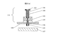
まず、板ばねを用いない構造例を説明する。図2(a)(b)、図3(a)(b)に一般的に用いられる2種類の復帰機構を有す打撃装置110,120を示す。図2(a)、図2(b)において、100はシャフト、101はシャフト先端に固定されたハンマー、102はシャフトの上端に設けられたツバ、103は中央に穴の開いたコイル、104はコイルばね、105はコイル103が固定されたベースを示す。ベース105には、シャフト100が通る穴106を設けている。107は検査対象物である。
First, an example of a structure that does not use a leaf spring will be described. 2A, 2B and 3A, 3B show
シャフト100はコイル103、コイルばね104、と嵌め合う。コイルばね104は所定量圧縮された状態でツバ102とコイル103の上面の間に挿入されており、シャフト100を上方に押し上げている。この状態でシャフト先端のハンマー101はコイルばね104により引っ張られベース105の下面108に当っている。この構造において、シャフト100とコイル103の組み合わせによって、通電することで直線駆動するソレノイドアクチュエータとなっている。
The
図2(a)の状態でコイル103に通電するとシャフト100は下方に移動し図2(b)の状態となり検査対象物107を打撃する。通電を停止するとコイルばね104の力によってシャフト100が上昇し図2(a)の状態に戻る。図2の構造においては、図2(b)に示すように、コイルばね104の圧縮長L1がシャフト長として必要となる。
When the
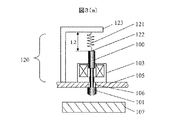
次に、図3(a)、図3(b)について説明する。 Next, FIG. 3A and FIG. 3B will be described.
図3(a)に示す打撃機構120においては、復帰用ばね121はシャフト100の先端122に固定し、他端はベース105に固定したブラケット123に固定している。コイル103に通電すると図3(b)に示す状態となり検査対象物107を打撃する。この構造においては、図3(a)におけるコイルばね長さL2が必要であり、さらにばね121を接続するブラケット123が必要となる。
In the
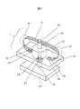
図1に本発明の実施例である打撃装置1の斜視図を示す、図4(a)に断面図を、図4(b)は図4(a)のAA矢印間の上面図を示す。
FIG. 4A is a perspective view of a
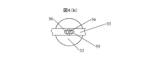
図1、図4(a)、図4(b)において30はシャフト、31はシャフト先端に固定したハンマー、32はコイルであり、シャフト30と摺動自在にはめあっている。33はベースであり、コイル32を固定している。ベース33にはシャフト30が通る穴34を設けている。35は板ばねでありシャフト30先端の係合部40において回動自在に係合している。板ばね35の端部37、38は、ねじ39によってベース35に固定している。板ばね35はシャフトとの係合部40から、端部37、38にかけて弾性力を発現する曲がり部41を設けている。シャフト先端のハンマー31の上部には、ハンマー緩衝部材50がシャフト30とはめあっており、ベース33の下面51と当接している。緩衝部材50は、ハンマー31による打撃復帰時に発生する音を抑制する。
In FIGS. 1, 4A, and 4B, 30 is a shaft, 31 is a hammer fixed to the tip of the shaft, and 32 is a coil, and is slidably fitted to the
図4(b)に示されるAA部上面図は、シャフト30と板ばね35の係合部40の断面を表している。係合部40において、板ばね35には長穴55があり、シャフト30に設けられた細径部56と回動自在にはめあっている。これは、板ばね35がシャフト30に対して固定された場合シャフトに30に横方向の力が働きシャフトの摺動を阻害するためである。
The top view of the AA portion shown in FIG. 4B represents a cross section of the engaging
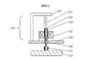
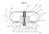
打撃機構1の動作を図5により説明する。図5(a)は初期状態を、図5(b)はコイル32に通電した打撃状態を表す。図5(a)では、シャフト30は板ばね35の弾性力によって上昇している。図5(b)はコイル32に通電することでシャフト30が下降し検査対象107を打撃している。このとき、板ばね35はコイル上面70近傍まで近づいている。距離L3は板ばね35の厚さ近くまで小さくすることが可能である。一例としては0.1〜0.3mm程度のものを用いた場合L3は1mm以下とすることができる。
The operation of the
本発明によれば、ハンマー部と駆動に必要なストローク、例えば図2(b)のL1,図3(a)のL2の長さを短縮できる。これにより、ハンマー部と駆動に必要なストロークに必要な寸法のみとなるため、ストローク方向の装置寸法を最小限のサイズにすることが出来る。 According to the present invention, it is possible to shorten the length of the hammer portion and the stroke required for driving, for example, L1 in FIG. 2B and L2 in FIG. Thereby, since it becomes only a dimension required for a hammer part and a stroke required for a drive, the apparatus dimension of a stroke direction can be made into the minimum size.
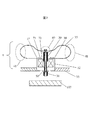
図6に第2の実施例である打撃装置2を示す。実施例1、図4(a)においてシャフト30に対して対称に配置した板ばね35を片側のみの非対称形状板ばね60にしたものであり、板ばねを片側としたことで更なる打撃装置の小型化が可能である。
FIG. 6 shows a
図7に第3の実施例である打撃装置3を示す。実施例1、図4(a)においてベース33に固定した板ばね35の端部37、38をコイル32の上面70にねじ71で固定したものである。これにより、ベース板に板ばねを固定する必要がないため打撃機構設置の自由度を高められる。
FIG. 7 shows a
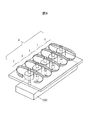
図8に第4の実施例である打撃装置4を示す。実施例1の打撃機構1を5個配置した多点打撃機構を示す。検査対象物200が細長く,打音が位置によってばらつく場合に対象物を高速に打撃できるため検査速度を高めることが可能となる。
FIG. 8 shows a striking device 4 according to a fourth embodiment. A multi-point hitting mechanism in which five
図9、図10は、本発明に関わる打撃装置を用いた打音収集装置の構成と使用状況を示す例である。 FIG. 9 and FIG. 10 are examples showing the configuration and usage status of the sound collection device using the batting device according to the present invention.
図9は、第1の実施例の打撃機構1を用いた打音収集装置を示す。打撃装置1のベース33に打音収集用マイク300を固定し、マイク300で収集された打撃音信号320は、マイク出力を調整するためのアンプ301、フィルタ302を通し、AD変換器により打音信号をデジタル化しマイクロコントローラ304に入力し、さらに記録手段306に記録される。また、コイル32に通電しシャフトを駆動するためのドライバ305をドライバを制御するためにマイクロコントローラ304に接続する。打音収集装置には取っ手400を固定している。
FIG. 9 shows a sound collecting device using the
タイル状に配列した検査サンプル311に対し作業者は取っ手を持って検査対象311に対して適当な距離で打撃装置を対向させる。次に、信号入力手段によってマイクロコントロール304に制御入力310を入力し、打撃装置1の打撃タイミングを制御しながらマイク300からの打音信号をメモリ306に記録し打音を収集する。作業者は、タイル状に並んだタイルに対し打音収集装置を適宜移動させながら打音収集動作を繰り返す。打撃機構1は小型軽量であることも含め、人間による検査用ハンマーでの官能判定作業に比べて作業性が改善する。
図10は、第4の実施例の打撃機構4を用いた打音収集装置340を示す。打撃機構5台の打撃用シャフトを駆動するために5台のドライバ315をマイクロコントローラ304で制御する構成としている。これにより、打撃装置5台を順次制御しながら、マイクからの信号320を順次処理し記録する。作業者は、取っ手401を持ってタイル状に配列した細長い検査サンプル341に対し打音収集装置を適宜移動させながら1個のタイルに対して打音5個ずつの収集動作を繰り返す。打撃機構が小型であるため1サンプルに対し複数打音収集が必要な場合でも小型で軽量な打音収集装置を構成できる。
The operator holds the hitting device at an appropriate distance from the
FIG. 10 shows a
なお、本発明は上記した実施例に限定されるものではなく、様々な変形例が含まれる。例えば、上記した実施例は本発明を分かりやすく説明するために詳細に説明したものであり、必ずしも説明した全ての構成を備えるものに限定されるものではない。また、ある実施例の構成の一部を他の実施例の構成に置き換えることが可能であり、また、ある実施例の構成に他の実施例の構成を加えることも可能である。また、各実施例の構成の一部について、他の構成の追加・削除・置換をすることが可能である。 In addition, this invention is not limited to an above-described Example, Various modifications are included. For example, the above-described embodiments have been described in detail for easy understanding of the present invention, and are not necessarily limited to those having all the configurations described. Further, a part of the configuration of one embodiment can be replaced with the configuration of another embodiment, and the configuration of another embodiment can be added to the configuration of one embodiment. Further, it is possible to add, delete, and replace other configurations for a part of the configuration of each embodiment.
30 シャフト
31 ハンマー
35 板ばね
32 コイル
30
Claims (8)
Priority Applications (1)
| Application Number | Priority Date | Filing Date | Title |
|---|---|---|---|
| JP2013183569A JP2015049236A (en) | 2013-09-05 | 2013-09-05 | Striking device for hammering test, and hammering test method |
Applications Claiming Priority (1)
| Application Number | Priority Date | Filing Date | Title |
|---|---|---|---|
| JP2013183569A JP2015049236A (en) | 2013-09-05 | 2013-09-05 | Striking device for hammering test, and hammering test method |
Publications (2)
| Publication Number | Publication Date |
|---|---|
| JP2015049236A true JP2015049236A (en) | 2015-03-16 |
| JP2015049236A5 JP2015049236A5 (en) | 2016-09-29 |
Family
ID=52699353
Family Applications (1)
| Application Number | Title | Priority Date | Filing Date |
|---|---|---|---|
| JP2013183569A Pending JP2015049236A (en) | 2013-09-05 | 2013-09-05 | Striking device for hammering test, and hammering test method |
Country Status (1)
| Country | Link |
|---|---|
| JP (1) | JP2015049236A (en) |
Cited By (3)
| Publication number | Priority date | Publication date | Assignee | Title |
|---|---|---|---|---|
| JP2018017730A (en) * | 2016-07-19 | 2018-02-01 | 株式会社トーキン | Hammering testing device and usage of the device |
| JP6327657B1 (en) * | 2017-12-13 | 2018-05-23 | 株式会社オンガエンジニアリング | Solenoid type electromagnetic hammer and control method thereof |
| WO2019146111A1 (en) * | 2018-01-29 | 2019-08-01 | 株式会社ドローンネット | Hammer test unit |
Citations (4)
| Publication number | Priority date | Publication date | Assignee | Title |
|---|---|---|---|---|
| JPH1157617A (en) * | 1997-08-26 | 1999-03-02 | Waka Seisakusho:Kk | Vibrating device and operating device provided with vibration function for game machine |
| JPH11202871A (en) * | 1998-01-14 | 1999-07-30 | Star Micronics Co Ltd | Percussion sound generating device |
| JP2000055893A (en) * | 1998-08-04 | 2000-02-25 | Akyuuto Kk | Hammering-sound generation apparatus |
| JP2013142598A (en) * | 2012-01-11 | 2013-07-22 | Hitachi Ltd | Fixing force measuring apparatus and measuring method |
-
2013
- 2013-09-05 JP JP2013183569A patent/JP2015049236A/en active Pending
Patent Citations (4)
| Publication number | Priority date | Publication date | Assignee | Title |
|---|---|---|---|---|
| JPH1157617A (en) * | 1997-08-26 | 1999-03-02 | Waka Seisakusho:Kk | Vibrating device and operating device provided with vibration function for game machine |
| JPH11202871A (en) * | 1998-01-14 | 1999-07-30 | Star Micronics Co Ltd | Percussion sound generating device |
| JP2000055893A (en) * | 1998-08-04 | 2000-02-25 | Akyuuto Kk | Hammering-sound generation apparatus |
| JP2013142598A (en) * | 2012-01-11 | 2013-07-22 | Hitachi Ltd | Fixing force measuring apparatus and measuring method |
Cited By (4)
| Publication number | Priority date | Publication date | Assignee | Title |
|---|---|---|---|---|
| JP2018017730A (en) * | 2016-07-19 | 2018-02-01 | 株式会社トーキン | Hammering testing device and usage of the device |
| JP6327657B1 (en) * | 2017-12-13 | 2018-05-23 | 株式会社オンガエンジニアリング | Solenoid type electromagnetic hammer and control method thereof |
| JP2019105552A (en) * | 2017-12-13 | 2019-06-27 | 株式会社オンガエンジニアリング | Solenoid type electromagnetic hammer and control method for the same |
| WO2019146111A1 (en) * | 2018-01-29 | 2019-08-01 | 株式会社ドローンネット | Hammer test unit |
Similar Documents
| Publication | Publication Date | Title |
|---|---|---|
| US7900498B1 (en) | Calibrated impact hammer | |
| JP6571088B2 (en) | Endoscope and method of using the same | |
| JP2015049236A (en) | Striking device for hammering test, and hammering test method | |
| JP6250241B1 (en) | Rotating electric machine wedge impact device and rotating electric machine wedge inspection system | |
| WO2015145914A1 (en) | Anchor-bolt evaluation system, and method and program for use therein | |
| JP2013152143A (en) | Striking device and internal state inspection device | |
| CN104515668A (en) | Ejection-type horizontal impact platform driven by air pressure | |
| CN110199183B (en) | Wedge loosening inspection device for rotating electric machine | |
| JP6057442B2 (en) | Impact testing machine | |
| JP6688619B2 (en) | Impact device used for impact elastic wave method | |
| JP2002119074A (en) | Drive using electromechanical sensing element | |
| JP2007024516A (en) | Drop impact testing device | |
| WO2010150109A1 (en) | Impact device for materials analysis | |
| CN100468025C (en) | Manual nail gun output testing device | |
| JP2011111159A (en) | Actuator device equipped with force sensor | |
| KR100950543B1 (en) | Integrity-diagnostic apparatus of concrete electric pole | |
| JP2015049236A5 (en) | ||
| TWI482917B (en) | Vibration damper and a method for operating a vibration-damping system having the same | |
| JP6387031B2 (en) | Concrete sounding device and concrete inspection method using the same | |
| JP5353767B2 (en) | Endurance test equipment | |
| JP2000055893A (en) | Hammering-sound generation apparatus | |
| JP7298922B2 (en) | Impact device for non-destructive testing and its control method | |
| JP5275384B2 (en) | Concrete column vibration device | |
| JP4369316B2 (en) | Nondestructive inspection equipment | |
| JP6277820B2 (en) | Head for impact test, hammer for impact test, impact test apparatus and impact test method |
Legal Events
| Date | Code | Title | Description |
|---|---|---|---|
| A521 | Request for written amendment filed |
Free format text: JAPANESE INTERMEDIATE CODE: A523 Effective date: 20160809 |
|
| A621 | Written request for application examination |
Free format text: JAPANESE INTERMEDIATE CODE: A621 Effective date: 20160809 |
|
| A977 | Report on retrieval |
Free format text: JAPANESE INTERMEDIATE CODE: A971007 Effective date: 20170705 |
|
| A131 | Notification of reasons for refusal |
Free format text: JAPANESE INTERMEDIATE CODE: A131 Effective date: 20170718 |
|
| A02 | Decision of refusal |
Free format text: JAPANESE INTERMEDIATE CODE: A02 Effective date: 20180206 |