JP2015045262A - Combined power apparatus, and marine vessel mounted with the same - Google Patents
Combined power apparatus, and marine vessel mounted with the same Download PDFInfo
- Publication number
- JP2015045262A JP2015045262A JP2013176580A JP2013176580A JP2015045262A JP 2015045262 A JP2015045262 A JP 2015045262A JP 2013176580 A JP2013176580 A JP 2013176580A JP 2013176580 A JP2013176580 A JP 2013176580A JP 2015045262 A JP2015045262 A JP 2015045262A
- Authority
- JP
- Japan
- Prior art keywords
- thermal expansion
- axial direction
- turbine
- combined power
- steam turbine
- Prior art date
- Legal status (The legal status is an assumption and is not a legal conclusion. Google has not performed a legal analysis and makes no representation as to the accuracy of the status listed.)
- Pending
Links
- NJPPVKZQTLUDBO-UHFFFAOYSA-N novaluron Chemical compound C1=C(Cl)C(OC(F)(F)C(OC(F)(F)F)F)=CC=C1NC(=O)NC(=O)C1=C(F)C=CC=C1F NJPPVKZQTLUDBO-UHFFFAOYSA-N 0.000 claims description 27
- 230000004323 axial length Effects 0.000 claims description 4
- 238000010276 construction Methods 0.000 abstract description 13
- 238000010248 power generation Methods 0.000 description 49
- 239000007789 gas Substances 0.000 description 13
- 230000009467 reduction Effects 0.000 description 7
- 230000008878 coupling Effects 0.000 description 5
- 238000010168 coupling process Methods 0.000 description 5
- 238000005859 coupling reaction Methods 0.000 description 5
- 230000008602 contraction Effects 0.000 description 4
- 238000010521 absorption reaction Methods 0.000 description 3
- XLYOFNOQVPJJNP-UHFFFAOYSA-N water Substances O XLYOFNOQVPJJNP-UHFFFAOYSA-N 0.000 description 3
- 238000005452 bending Methods 0.000 description 2
- 239000003638 chemical reducing agent Substances 0.000 description 2
- 238000010586 diagram Methods 0.000 description 2
- 230000006872 improvement Effects 0.000 description 2
- 230000004048 modification Effects 0.000 description 2
- 238000012986 modification Methods 0.000 description 2
- 230000001360 synchronised effect Effects 0.000 description 2
- 229910000831 Steel Inorganic materials 0.000 description 1
- 230000008859 change Effects 0.000 description 1
- 239000000567 combustion gas Substances 0.000 description 1
- 230000007423 decrease Effects 0.000 description 1
- 238000006073 displacement reaction Methods 0.000 description 1
- 238000000605 extraction Methods 0.000 description 1
- 239000004519 grease Substances 0.000 description 1
- 239000007788 liquid Substances 0.000 description 1
- 239000000463 material Substances 0.000 description 1
- 238000004904 shortening Methods 0.000 description 1
- 125000006850 spacer group Chemical group 0.000 description 1
- 239000010959 steel Substances 0.000 description 1
Images


Classifications
-
- B—PERFORMING OPERATIONS; TRANSPORTING
- B63—SHIPS OR OTHER WATERBORNE VESSELS; RELATED EQUIPMENT
- B63H—MARINE PROPULSION OR STEERING
- B63H21/00—Use of propulsion power plant or units on vessels
- B63H21/02—Use of propulsion power plant or units on vessels the vessels being steam-driven
- B63H21/06—Use of propulsion power plant or units on vessels the vessels being steam-driven relating to steam turbines
-
- F—MECHANICAL ENGINEERING; LIGHTING; HEATING; WEAPONS; BLASTING
- F01—MACHINES OR ENGINES IN GENERAL; ENGINE PLANTS IN GENERAL; STEAM ENGINES
- F01D—NON-POSITIVE DISPLACEMENT MACHINES OR ENGINES, e.g. STEAM TURBINES
- F01D25/00—Component parts, details, or accessories, not provided for in, or of interest apart from, other groups
- F01D25/28—Supporting or mounting arrangements, e.g. for turbine casing
-
- F—MECHANICAL ENGINEERING; LIGHTING; HEATING; WEAPONS; BLASTING
- F01—MACHINES OR ENGINES IN GENERAL; ENGINE PLANTS IN GENERAL; STEAM ENGINES
- F01K—STEAM ENGINE PLANTS; STEAM ACCUMULATORS; ENGINE PLANTS NOT OTHERWISE PROVIDED FOR; ENGINES USING SPECIAL WORKING FLUIDS OR CYCLES
- F01K23/00—Plants characterised by more than one engine delivering power external to the plant, the engines being driven by different fluids
- F01K23/02—Plants characterised by more than one engine delivering power external to the plant, the engines being driven by different fluids the engine cycles being thermally coupled
- F01K23/06—Plants characterised by more than one engine delivering power external to the plant, the engines being driven by different fluids the engine cycles being thermally coupled combustion heat from one cycle heating the fluid in another cycle
- F01K23/065—Plants characterised by more than one engine delivering power external to the plant, the engines being driven by different fluids the engine cycles being thermally coupled combustion heat from one cycle heating the fluid in another cycle the combustion taking place in an internal combustion piston engine, e.g. a diesel engine
-
- F—MECHANICAL ENGINEERING; LIGHTING; HEATING; WEAPONS; BLASTING
- F02—COMBUSTION ENGINES; HOT-GAS OR COMBUSTION-PRODUCT ENGINE PLANTS
- F02C—GAS-TURBINE PLANTS; AIR INTAKES FOR JET-PROPULSION PLANTS; CONTROLLING FUEL SUPPLY IN AIR-BREATHING JET-PROPULSION PLANTS
- F02C3/00—Gas-turbine plants characterised by the use of combustion products as the working fluid
- F02C3/04—Gas-turbine plants characterised by the use of combustion products as the working fluid having a turbine driving a compressor
- F02C3/10—Gas-turbine plants characterised by the use of combustion products as the working fluid having a turbine driving a compressor with another turbine driving an output shaft but not driving the compressor
-
- F—MECHANICAL ENGINEERING; LIGHTING; HEATING; WEAPONS; BLASTING
- F02—COMBUSTION ENGINES; HOT-GAS OR COMBUSTION-PRODUCT ENGINE PLANTS
- F02C—GAS-TURBINE PLANTS; AIR INTAKES FOR JET-PROPULSION PLANTS; CONTROLLING FUEL SUPPLY IN AIR-BREATHING JET-PROPULSION PLANTS
- F02C6/00—Plural gas-turbine plants; Combinations of gas-turbine plants with other apparatus; Adaptations of gas-turbine plants for special use
- F02C6/04—Gas-turbine plants providing heated or pressurised working fluid for other apparatus, e.g. without mechanical power output
- F02C6/10—Gas-turbine plants providing heated or pressurised working fluid for other apparatus, e.g. without mechanical power output supplying working fluid to a user, e.g. a chemical process, which returns working fluid to a turbine of the plant
- F02C6/12—Turbochargers, i.e. plants for augmenting mechanical power output of internal-combustion piston engines by increase of charge pressure
-
- F—MECHANICAL ENGINEERING; LIGHTING; HEATING; WEAPONS; BLASTING
- F02—COMBUSTION ENGINES; HOT-GAS OR COMBUSTION-PRODUCT ENGINE PLANTS
- F02C—GAS-TURBINE PLANTS; AIR INTAKES FOR JET-PROPULSION PLANTS; CONTROLLING FUEL SUPPLY IN AIR-BREATHING JET-PROPULSION PLANTS
- F02C6/00—Plural gas-turbine plants; Combinations of gas-turbine plants with other apparatus; Adaptations of gas-turbine plants for special use
- F02C6/18—Plural gas-turbine plants; Combinations of gas-turbine plants with other apparatus; Adaptations of gas-turbine plants for special use using the waste heat of gas-turbine plants outside the plants themselves, e.g. gas-turbine power heat plants
-
- B—PERFORMING OPERATIONS; TRANSPORTING
- B63—SHIPS OR OTHER WATERBORNE VESSELS; RELATED EQUIPMENT
- B63J—AUXILIARIES ON VESSELS
- B63J3/00—Driving of auxiliaries
- B63J3/02—Driving of auxiliaries from propulsion power plant
-
- F—MECHANICAL ENGINEERING; LIGHTING; HEATING; WEAPONS; BLASTING
- F01—MACHINES OR ENGINES IN GENERAL; ENGINE PLANTS IN GENERAL; STEAM ENGINES
- F01D—NON-POSITIVE DISPLACEMENT MACHINES OR ENGINES, e.g. STEAM TURBINES
- F01D15/00—Adaptations of machines or engines for special use; Combinations of engines with devices driven thereby
- F01D15/02—Adaptations for driving vehicles, e.g. locomotives
- F01D15/04—Adaptations for driving vehicles, e.g. locomotives the vehicles being waterborne vessels
-
- F—MECHANICAL ENGINEERING; LIGHTING; HEATING; WEAPONS; BLASTING
- F01—MACHINES OR ENGINES IN GENERAL; ENGINE PLANTS IN GENERAL; STEAM ENGINES
- F01D—NON-POSITIVE DISPLACEMENT MACHINES OR ENGINES, e.g. STEAM TURBINES
- F01D15/00—Adaptations of machines or engines for special use; Combinations of engines with devices driven thereby
- F01D15/12—Combinations with mechanical gearing
-
- F—MECHANICAL ENGINEERING; LIGHTING; HEATING; WEAPONS; BLASTING
- F05—INDEXING SCHEMES RELATING TO ENGINES OR PUMPS IN VARIOUS SUBCLASSES OF CLASSES F01-F04
- F05D—INDEXING SCHEME FOR ASPECTS RELATING TO NON-POSITIVE-DISPLACEMENT MACHINES OR ENGINES, GAS-TURBINES OR JET-PROPULSION PLANTS
- F05D2220/00—Application
- F05D2220/40—Application in turbochargers
-
- F—MECHANICAL ENGINEERING; LIGHTING; HEATING; WEAPONS; BLASTING
- F05—INDEXING SCHEMES RELATING TO ENGINES OR PUMPS IN VARIOUS SUBCLASSES OF CLASSES F01-F04
- F05D—INDEXING SCHEME FOR ASPECTS RELATING TO NON-POSITIVE-DISPLACEMENT MACHINES OR ENGINES, GAS-TURBINES OR JET-PROPULSION PLANTS
- F05D2260/00—Function
- F05D2260/40—Transmission of power
- F05D2260/403—Transmission of power through the shape of the drive components
- F05D2260/4031—Transmission of power through the shape of the drive components as in toothed gearing
-
- Y—GENERAL TAGGING OF NEW TECHNOLOGICAL DEVELOPMENTS; GENERAL TAGGING OF CROSS-SECTIONAL TECHNOLOGIES SPANNING OVER SEVERAL SECTIONS OF THE IPC; TECHNICAL SUBJECTS COVERED BY FORMER USPC CROSS-REFERENCE ART COLLECTIONS [XRACs] AND DIGESTS
- Y02—TECHNOLOGIES OR APPLICATIONS FOR MITIGATION OR ADAPTATION AGAINST CLIMATE CHANGE
- Y02T—CLIMATE CHANGE MITIGATION TECHNOLOGIES RELATED TO TRANSPORTATION
- Y02T70/00—Maritime or waterways transport
- Y02T70/50—Measures to reduce greenhouse gas emissions related to the propulsion system
Landscapes
- Engineering & Computer Science (AREA)
- Chemical & Material Sciences (AREA)
- Combustion & Propulsion (AREA)
- Mechanical Engineering (AREA)
- General Engineering & Computer Science (AREA)
- Ocean & Marine Engineering (AREA)
- Chemical Kinetics & Catalysis (AREA)
- General Chemical & Material Sciences (AREA)
- Engine Equipment That Uses Special Cycles (AREA)
Abstract
Description
本発明は、パワータービンの出力軸と蒸気タービンの出力軸とがクラッチ装置を介して連結され、各々のタービンの回転出力によって発電機等を駆動するように構成されたコンバインド動力装置およびこれを搭載した船舶に関するものである。上記のクラッチ装置とは、各タービンの回転速度に応じて嵌脱が行われるため、例えば、蒸気タービンの出力のみによる発電機等の駆動、または蒸気タービンとパワータービンの合計出力による駆動が可能なものである。 The present invention relates to a combined power unit configured such that an output shaft of a power turbine and an output shaft of a steam turbine are connected via a clutch device, and a generator or the like is driven by the rotational output of each turbine, and the same Related to the ship. Since the above clutch device is fitted and disengaged according to the rotational speed of each turbine, for example, it is possible to drive a generator or the like only by the output of the steam turbine or drive by the total output of the steam turbine and the power turbine It is.
特許文献1に開示されているように、パワータービンと蒸気タービンとが同軸上に配置され、これら各々のタービンの回転出力によって発電機を駆動するように構成されたコンバインド発電装置において、蒸気タービンまたはパワータービンの一方を基礎部に固定させ、他方を基礎部に対して軸方向に撓み自在に固定することにより、蒸気タービンおよびパワータービンの熱膨張による軸方向への伸びを吸収するようにしたものが知られている。
As disclosed in
あるいは、図14に示す従来のコンバインド発電装置100のように、基礎部1の上面にパワータービン2と蒸気タービン3の両方を固定させ、パワータービン2から延びる出力軸4,5と、蒸気タービン3から延びる出力軸6との間をクラッチ装置7で連結し、出力軸4と出力軸6とに、それぞれ軸方向Lの伸び縮みを許容する撓み継手8,9を設けることにより、パワータービン2と蒸気タービン3の軸方向Lの熱膨張を吸収するようにしたものがある。
Alternatively, as in the conventional combined
クラッチ装置7としては、一般にSSSクラッチ(Synchro-Self-Shifting Clutch)と呼ばれる自動嵌脱式クラッチが用いられるが、この自動嵌脱式クラッチは軸方向Lの熱膨張吸収容量が小さい。このため、撓み継手8,9としては熱膨張吸収容量の大きいダイヤフラムカップリングが適している。なお、パワータービン2から延びる出力軸4,5の間には、パワータービン2の回転速度を蒸気タービン3の回転速度に一致させるための減速装置10が設けられている。
As the
蒸気タービン3は、その車室の一端が熱膨張起点11となっている。この熱膨張起点11としては、蒸気タービン3の反クラッチ装置7側の軸受支持部を例示することができる。この熱膨張起点11と、クラッチ7側の軸受支持部12とが基礎部1に固定され、熱膨張起点11と軸受支持部12との間に撓み継手9が設けられている。また、蒸気タービン3には軸13を介して発電機14が連結されている。
The
なお、図14の軸受支持部12等の支持部において、その先端に矢印があるものは軸の回転と軸方向へ移動を許容しながら荷重を支持するもの、支持部の先端に矢印が無いものは軸方向への移動を許容しないで荷重を支持するものである。また、軸受支持部12等の支持部の基礎部1付近の○は、基礎部1に対する固定部分を意味するものである。
In addition, in the support portion such as the
このように構成されたコンバインド発電装置100においては、パワータービン2の出力軸4と蒸気タービン3の出力軸6の回転速度が減速装置10を介して一致(シンクロ)すると、クラッチ装置7が自動的に結合され、パワータービン2と蒸気タービン3の回転出力によって発電機14が駆動され、発電が行われる。
In the combined
特許文献1のコンバインド発電装置では、軸方向の熱膨張を考慮して、蒸気タービンまたはパワータービンの一方が他方に対して軸方向に撓み自在に固定されているため、パワータービンと蒸気タービンと発電機との軸方向のアライメントに誤差が発生する懸念がある。
In the combined power generation apparatus disclosed in
また、図14に示す従来のコンバインド発電装置100の場合は、出力軸4,6に撓み継手8,9を介装することによって軸方向Lの熱膨張を吸収しているため、撓み継手8,9を含む出力軸4,6が長くなり、コンバインド発電装置100が大型化するとともに、アライメント精度が低下してしまうという問題があった。
Further, in the case of the conventional combined
さらに、撓み継手8,9を複数設置することでコストアップになることに加えて、図示しない中間接続軸やその軸受等も必要であり、全体の部品点数が増大してしまう。また、撓み継手8,9として高価なダイヤフラムカップリングが適用されることと相まって、コンバインド発電装置の建設コストが高くなるという問題もあった。
撓み継手8,9は、フレキシブル部分を保有し、熱膨張を吸収できる高価な継手である。撓み継手を1個に省略することで、コンパクト化と低コスト化が可能になるだけでなく、パワータービン2と蒸気タービン3を設置する際の出力軸の回転芯合せ作業を容易化する効果を奏する。
Furthermore, in addition to increasing the cost by installing a plurality of
The
本発明は、このような事情に鑑みてなされたものであって、タービンの熱膨張による応力がクラッチ装置に及ばないようにして撓み継手の数量を削減し、小型化と建設コスト削減、およびアライメント精度の向上を実現することのできるコンバインド動力装置およびこれを搭載した船舶を提供することを目的とする。 The present invention has been made in view of such circumstances, and reduces the number of flexible joints so that stress due to thermal expansion of the turbine does not reach the clutch device, thereby reducing the size and construction cost, and alignment. It is an object of the present invention to provide a combined power device capable of improving accuracy and a ship equipped with the same.
上記課題を解決するために、本発明のコンバインド動力装置は以下の手段を採用する。 In order to solve the above problems, the combined power unit of the present invention employs the following means.
即ち、本発明に係るコンバインド動力装置は、基礎部の上面に設置されたパワータービンと蒸気タービンの各々の出力軸がクラッチ装置を介して連結可能なコンバインド動力装置であって、前記パワータービンおよび前記蒸気タービンのうちの、少なくとも熱膨張量の大きいタービンは、その軸方向の一端が熱膨張起点として前記基礎部の上面に固定され、前記軸方向の他端が熱膨張移動点として前記基礎部の上面に対して前記軸方向に移動可能に配置されるとともに、前記熱膨張移動点の移動による応力が前記クラッチ装置に及ぶことを防止する相対移動構造が設けられていることを特徴とする。 That is, the combined power device according to the present invention is a combined power device in which the output shafts of the power turbine and the steam turbine installed on the upper surface of the base portion can be connected via a clutch device, the power turbine and the power turbine Among the steam turbines, at least a turbine having a large thermal expansion amount, one end in the axial direction is fixed to the upper surface of the foundation portion as a thermal expansion starting point, and the other end in the axial direction is a thermal expansion movement point as the thermal expansion movement point. A relative movement structure is provided which is arranged so as to be movable in the axial direction with respect to the upper surface and prevents stress due to movement of the thermal expansion movement point from reaching the clutch device.
上記構成によれば、二種のタービンのうち、少なくとも熱膨張量の大きいタービンが軸方向に熱膨張した場合に、当該タービンの熱膨張起点は基礎部に対して動かず、熱膨張移動点は基礎部に対して軸方向に移動する。その時、相対移動構造により、熱膨張移動点の移動による応力がクラッチ装置に及ぶことが防止される。 According to the above configuration, when a turbine having at least a large amount of thermal expansion out of the two types of turbines thermally expands in the axial direction, the thermal expansion start point of the turbine does not move relative to the base portion, and the thermal expansion transfer point is Move axially relative to the foundation. At that time, the relative movement structure prevents the stress due to the movement of the thermal expansion movement point from reaching the clutch device.
このため、タービンの熱膨張を吸収するための撓み継手の数量を削減することができ、これによってコンバインド動力装置を軸方向に短縮して小型化するとともに、その建設コストを削減することができる。 For this reason, the number of flexible joints for absorbing the thermal expansion of the turbine can be reduced, whereby the combined power unit can be shortened in the axial direction and reduced in size, and the construction cost can be reduced.
なお、前記相対移動構造として、前記熱膨張起点を前記タービンの前記クラッチ装置側に設け、前記熱膨張移動点を前記タービンの前記クラッチ装置の反対側に設けることが考えられる。こうすれば、タービンが軸方向に熱膨張した場合に、当該タービンの軸方向寸法が伸びる方向が反クラッチ装置側の方向となるため、撓み継手を設けることなく、簡素で安価な構造により、タービンの熱膨張を吸収し、熱膨張による応力がクラッチ装置に及ぶことを防止することができる。
しかも、タービンとクラッチ装置との間に撓み継手を設けなくてもよいことから、タービンとクラッチ装置との間の軸長を短くすることができ、これによって芯ずれが起こりにくくなるため、アライメント精度を向上させることができる。
As the relative movement structure, it is conceivable that the thermal expansion starting point is provided on the clutch device side of the turbine, and the thermal expansion movement point is provided on the opposite side of the turbine of the clutch device. In this way, when the turbine thermally expands in the axial direction, the direction in which the axial dimension of the turbine extends becomes the direction on the anti-clutch device side. Therefore, the turbine can be configured with a simple and inexpensive structure without providing a flexible joint. It is possible to prevent the stress caused by the thermal expansion from reaching the clutch device.
In addition, since there is no need to provide a flexible joint between the turbine and the clutch device, the axial length between the turbine and the clutch device can be shortened, which makes it difficult for misalignment to occur. Can be improved.
また、本発明に係るコンバインド動力装置は、上記構成において、前記熱膨張移動点は、前記基礎部の上面に対して前記軸方向に移動可能に設置された移動台座の上に固定されていることを特徴とする。 Further, in the combined power device according to the present invention, in the above configuration, the thermal expansion movement point is fixed on a movable pedestal installed so as to be movable in the axial direction with respect to the upper surface of the base portion. It is characterized by.
上記構成によれば、タービンが軸方向に熱膨張した場合には、当該タービンの熱膨張移動点が移動台座により基礎部の上面を軸方向に、且つクラッチ装置の反対側に移動し、これによってタービンの熱膨張がスムーズに吸収され、熱膨張に伴う応力がクラッチ装置に及ぶことが防止される。 According to the above configuration, when the turbine is thermally expanded in the axial direction, the thermal expansion movement point of the turbine is moved in the axial direction on the upper surface of the base portion by the moving base and on the opposite side of the clutch device, thereby The thermal expansion of the turbine is absorbed smoothly, and the stress accompanying the thermal expansion is prevented from reaching the clutch device.
また、本発明に係るコンバインド動力装置は、上記構成において、前記移動台座は、前記基礎部の上面との間に形成されて前記軸方向に沿うキー溝と、このキー溝に嵌合されるキーとによって前記軸方向に移動可能とされ、前記キーは、前記軸方向の長さが前記移動台座の前記軸方向に沿う寸法よりも短くされるとともに、前記キー溝の内部で微小角度の回動が可能な回転中心を備え、前記軸方向に沿って離間して複数個配置されていることを特徴とする。 In the combined power unit according to the present invention, in the above configuration, the moving base is formed between the upper surface of the base portion and a key groove along the axial direction, and a key fitted in the key groove. The key can be moved in the axial direction, and the length of the key in the axial direction can be made shorter than the dimension along the axial direction of the movable pedestal. A plurality of rotation centers are provided, and a plurality of rotation centers are arranged apart from each other in the axial direction.
上記構成によれば、タービンの熱を受けて移動台座やキー、キー溝が熱膨張して僅かに変形したとしても、キーがキー溝の内部で微小角度回動することにより、上記の変形が吸収される。したがって、簡素な構造により、アライメント精度を向上させることができる。 According to the above configuration, even if the moving pedestal, the key, and the keyway are thermally expanded due to the heat of the turbine, the key is rotated by a minute angle inside the keyway, so that the above deformation is caused. Absorbed. Therefore, alignment accuracy can be improved with a simple structure.
また、本発明に係るコンバインド動力装置は、上記構成において、前記相対移動構造は、前記基礎部の上面に対して前記軸方向に移動可能に設置された移動台座の上に、前記熱膨張移動点と前記クラッチ装置とが設置された構造であることを特徴とする。 In the combined power unit according to the present invention, in the configuration described above, the relative movement structure has the thermal expansion moving point on a moving pedestal that is movably installed in the axial direction with respect to the upper surface of the base portion. And the clutch device.
上記構成によれば、タービンが軸方向に熱膨張した場合、当該タービンの熱膨張移動点とクラッチ装置とが、共に移動台座の上に載った状態で基礎部の上面を軸方向に移動する。このため、タービンの熱膨張移動点とクラッチ装置との間に相対移動がない。
したがって、タービンとクラッチ装置との間に撓み継手を設ける必要がなく、撓み継手を削減できることから、コンバインド動力装置を軸方向に短縮し、小型化するとともに、その建設コストを削減することができる。
According to the above configuration, when the turbine is thermally expanded in the axial direction, the thermal expansion moving point of the turbine and the clutch device move in the axial direction on the upper surface of the base portion in a state where both are placed on the moving base. For this reason, there is no relative movement between the thermal expansion movement point of the turbine and the clutch device.
Therefore, it is not necessary to provide a flexible joint between the turbine and the clutch device, and the number of flexible joints can be reduced. Therefore, the combined power unit can be shortened in the axial direction, downsized, and the construction cost can be reduced.
また、本発明に係るコンバインド動力装置は、前記相対移動構造における前記熱膨張移動点は、可撓性支持部を介して前記基礎部の上面に連結され、前記可撓性支持部は、前記熱膨張移動点を前記基礎部の上面に連結しながら前記軸方向に撓むことにより、前記熱膨張移動点の前記軸方向への移動を許容するものであることを特徴とする。 In the combined power device according to the present invention, the thermal expansion movement point in the relative movement structure is connected to the upper surface of the base portion via a flexible support portion, and the flexible support portion is The movement of the thermal expansion movement point in the axial direction is permitted by bending in the axial direction while connecting the expansion movement point to the upper surface of the base portion.
上記構成によれば、タービンが軸方向に熱膨張した場合には、可撓性支持部が軸方向に沿って撓むことにより、当該タービンの熱膨張移動点が基礎部の上面を軸方向に、且つクラッチ装置の反対側に移動し、熱膨張が吸収される。
可撓性支持部は可撓性のある板材等によって非常に簡素に形成できるため、コンバインド動力装置の建設コストを低減するとともに、高い信頼性を得ることができる。
しかも、可撓性支持部はタービンの軸方向に撓むため、可撓性支持部が撓むことによりタービンの軸方向のアライメントに誤差が発生する虞がなく、アライメント精度を向上させることができる。
According to the above configuration, when the turbine thermally expands in the axial direction, the flexible support portion bends along the axial direction, so that the thermal expansion movement point of the turbine moves the upper surface of the base portion in the axial direction. , And move to the opposite side of the clutch device to absorb thermal expansion.
Since the flexible support portion can be formed very simply by a flexible plate or the like, it is possible to reduce the construction cost of the combined power unit and to obtain high reliability.
Moreover, since the flexible support portion bends in the axial direction of the turbine, there is no possibility that an error occurs in the alignment in the axial direction of the turbine due to the flexure of the flexible support portion, and the alignment accuracy can be improved. .
また、本発明に係る船舶は、上記のいずれかのコンバインド動力装置を搭載したことを特徴とする。 Moreover, the ship which concerns on this invention mounted one of said combined power apparatuses.
この船舶によれば、コンバインド動力装置におけるタービンの熱膨張による応力がクラッチ装置に及ばないため、タービンとクラッチ装置との間に撓み継手を設けなくてもよい。
これにより、コンバインド動力装置の軸方向寸法が短縮されるため、船体内部のスペース占有率が小さくて済む。このため、船体内のレイアウト性が良くなり、設計の自由度を高めることができる。
しかも、コスト的に高価な撓み継手の数量を削減できるため、コンバインド動力装置の価格、ひいては船体の価格を安くすることができる。
According to this ship, since the stress due to the thermal expansion of the turbine in the combined power device does not reach the clutch device, it is not necessary to provide a flexible joint between the turbine and the clutch device.
Thereby, since the axial direction dimension of a combined power unit is shortened, the space occupation rate inside a hull may be small. For this reason, the layout within the hull is improved, and the degree of freedom in design can be increased.
In addition, since the number of costly expensive flexible joints can be reduced, it is possible to reduce the price of the combined power unit, and hence the price of the hull.
以上のように、本発明に係るコンバインド動力装置によれば、タービンの熱膨張による応力がクラッチ装置に及ばないようにして撓み継手の数量を削減し、小型化と建設コスト削減、およびアライメント精度の向上を実現することができる。 As described above, according to the combined power device according to the present invention, the number of flexible joints is reduced so that the stress due to the thermal expansion of the turbine does not reach the clutch device, and the size, construction cost, and alignment accuracy are reduced. Improvements can be realized.
また、本発明に係るコンバインド動力装置を搭載した船舶によれば、タービンの熱膨張による応力がクラッチ装置に及ばないため、タービンとクラッチ装置との間に設ける撓み継手を削減し、コンバインドサイクル発電装置の軸方向寸法を短縮して船体内のレイアウト性および設計の自由度を向上させるとともに、船体価格を安くすることができる。 Further, according to the ship equipped with the combined power device according to the present invention, since the stress due to the thermal expansion of the turbine does not reach the clutch device, the flexible joint provided between the turbine and the clutch device is reduced, and the combined cycle power generation device The axial dimensions of the hull can be shortened to improve the layout of the hull and the degree of design freedom, and the hull price can be reduced.
以下に、本発明に係るコンバインド動力装置の複数の実施形態について、図面を参照して説明する。 Hereinafter, a plurality of embodiments of a combined power device according to the present invention will be described with reference to the drawings.
〔第1実施形態〕
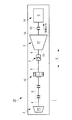
図1は、本発明に係るコンバインド動力装置が発電装置として適用された船舶の発電系統の概略構成図である。
この発電系統200は、船舶推進用のディーゼルエンジン203と、排気ターボ過給機205と、パワータービン(ガスタービン)2と、蒸気タービン3と、排気ガス熱交換器としての排ガスエコノマイザ211とを具備して構成されている。排気ターボ過給機205は、タービン部205aと、コンプレッサ部205bと、その間を連結する回転軸205cとより構成されている。ディーゼルエンジン203からの出力は図示しないプロペラ軸を介してスクリュープロペラに直接的または間接的に接続されている。
[First Embodiment]
FIG. 1 is a schematic configuration diagram of a power generation system of a ship to which a combined power device according to the present invention is applied as a power generation device.
The
また、ディーゼルエンジン203の各気筒のシリンダ部213の排気ポートは排気ガス集合管としての排気マニホールド215に接続され、排気マニホールド215は、第1排気管L1を介して排気ターボ過給機205のタービン部205aの入口側と接続され、また、排気マニホールド215は第2排気管L2(抽気通路)を介してパワータービン2の入口側と接続されて、排気ガスの一部が、排気ターボ過給機205に供給される前に抽気されてパワータービン2に供給されるようになっている。
The exhaust port of the
一方、各シリンダ部213の給気ポートは給気マニホールド217に接続されており、給気マニホールド217は、給気管K1を介して排気ターボ過給機205のコンプレッサ部205bと接続している。また、給気管K1には空気冷却器(インタークーラ)219が設置されている。
On the other hand, the air supply port of each
パワータービン2は、第2排気管L2を介して排気マニホールド215から抽気された排気ガスによって回転駆動されるようになっており、また、蒸気タービン3は、排ガスエコノマイザ211によって生成された蒸気が供給されて回転駆動されるようになっている。
The
排ガスエコノマイザ211においては、排気ターボ過給機205のタービン部205aの出口側から第3排気管L3を介して排出される排気ガスと、パワータービン2の出口側から第4排気管L4を介して排出される排気ガスとが導入され、熱交換部221において排気ガスの熱と給水管223を流れる水とが熱交換されて水から蒸気が発生する。
In the
このように排ガスエコノマイザ211で生成された蒸気は、第1蒸気管J1を介して蒸気タービン3に導入され、また、該蒸気タービン3で仕事を終えた蒸気は第2蒸気管J2によって排出されて図示しないコンデンサ(復水器)に導かれるようになっている。
The steam thus generated by the
パワータービン2と蒸気タービン3は直列に結合され、軸13を介して発電機14を駆動するようになっている。また、パワータービン2の出力軸4はクラッチ装置7(SSSクラッチ)を介して蒸気タービン9の出力軸6と連結されている。
The
そして、パワータービン2と、蒸気タービン3と、クラッチ装置7と、減速装置10と、発電機14とを含んでコンバインド発電装置30(コンバインド動力装置)が構成されている。このコンバインド発電装置30においては、船舶推進用のディーゼルエンジン203の排気ガス(燃焼ガス)の排気エネルギーを動力として駆動されるようになっており、排気エネルギーを効率良く回収することができる。
A combined power generation device 30 (combined power device) is configured including the
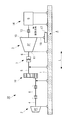
図2は、本発明の第1実施形態を示すコンバインド発電装置30の側面図であり、図3は同じく平面図である。このコンバインド発電装置30は、図14に示す従来のコンバインド発電装置100と同様に、基礎部1の上面に設置されたパワータービン2から減速装置10を介して回転が伝えられる出力軸4,5と、同じく基礎部1の上面に設置された蒸気タービン3から延びる出力軸6との間がクラッチ装置7で連結され、これら二種のタービン2,3の合成出力によって発電機14を駆動するように構成されている。なお、蒸気タービン3と発電機14との間を連結している軸13には、その軸方向Lの伸縮を吸収可能なカップリング等が介装されている。
FIG. 2 is a side view of the combined
パワータービン2の回転速度は15000〜25000rpm程度である一方、蒸気タービン3の回転速度は6000〜12000rpm程度であり、両タービン2,3の回転速度に差があるので、減速装置10によりパワータービン2の出力軸4の回転速度を減速し、両タービン2,3の回転速度を一致(シンクロ)させるようになっている。
While the rotational speed of the
このコンバインド発電装置30においては、例えばエンジン負荷が50%程度でエンジン排気からの回収熱によって生成した蒸気を蒸気タービン3に供給することで蒸気タービン3の回転が開始され、蒸気タービン3の内部温度は300℃程度に上昇する。エンジン負荷が上昇し排気量が増加した場合に、エンジン排気の一部をパワータービン2に供給することでパワータービン2の回転が開始され、パワータービン2の内部温度は400℃〜500℃程度に上昇する。
In this combined
パワータービン2と蒸気タービン3の熱膨張量を詳細に計測した結果、熱膨張量がより大きいのは蒸気タービン3であり、その軸方向Lに沿う熱膨張量は数ミリ以上になる。パワータービン2の軸方向Lに沿う熱膨張量は、蒸気タービン3の1/2〜1/5以下と比較的小さいことが判明しており、故に蒸気タービン3の出力軸6の熱膨張量吸収が重要である。
As a result of measuring the thermal expansion amounts of the
蒸気タービン3は、その軸方向Lの一端が熱膨張起点11として基礎部1の上面に固定されている。この熱膨張起点11としては、蒸気タービン3のクラッチ装置7側の軸受支持部を例示することができる。
One end of the
また、蒸気タービン3の軸方向Lの他端が熱膨張移動点15となっており、基礎部1の上面に対して軸方向Lに移動可能に配置されている。この熱膨張移動点15としては、蒸気タービン3の反クラッチ装置7側の軸受支持部を例示することができる。
Further, the other end of the
そして、蒸気タービン3が熱膨張した際に、その熱膨張移動点15が軸方向Lに移動しても、クラッチ装置7に応力が及ぶことが無いように、相対移動構造Aが設けられている。この相対移動構造Aは、熱膨張起点11を蒸気タービン3のクラッチ装置7側に向け、熱膨張移動点15を蒸気タービン3のクラッチ装置7の反対側に向けた構造となっている。
Further, when the
熱膨張移動点15は、支持部16を介して移動台座17の上に固定されている。移動台座17は、基礎部1の上面に対して軸方向Lに移動可能に設置されている。図4に示すように、移動台座17は、その両辺部17aが複数の段付ボルト18によって基礎部1の上面に締結され、基礎部1の上面からの浮き上がりを防止されている。
The thermal
段付ボルト18には、その頭部に続く段部18aが設けられている。段部18aの外径はネジ部18bの外径よりも大きく、段部18aの長さは両辺部17aの厚みよりも僅かに長くされている。このため、段付ボルト18が基礎部1に締め込まれても、その締結力は両辺部17aに加わらない。
The stepped
また、両辺部17aに穿設されているボルト穴17bは、軸方向Lに沿う長穴であり、段付ボルト18の段部18aが挿通可能な内幅を持っている。このため、移動台座17は、ボルト18の段部18aがボルト穴17bの中を相対移動できる分だけ、基礎部1の上面を軸方向Lにスライドすることができ、支持部16を介して熱膨張移動点15を軸方向Lに移動させることができる。なお、段付ボルト18の代わりに、段部18aと同じ長さの筒状スペーサーを環装したボルトを用いてもよい。
Moreover, the
さらに、移動台座17は、基礎部1の上面との間に形成されて軸方向Lに沿うキー溝20と、このキー溝20に嵌合されるキー21とにより、軸方向Lに移動可能となるようガイドされている。キー21は移動台座17のL方向全長に近い長さを所有してもよいし、複数に分割されていてもよい。
Further, the
以上のように構成されたコンバインド発電装置30は、上記のように、蒸気タービン3の熱膨張起点11がクラッチ装置7側に向けられて基礎部1の上面に固定され、蒸気タービン3の熱膨張移動点15がクラッチ装置7の反対側に向けられるとともに基礎部1の上面に対して軸方向Lにのみ移動可能に設置された移動台座17の上に固定された相対移動構造Aを備えている。
As described above, the combined
このため、蒸気タービン3が軸方向Lに沿って熱膨張した場合に、蒸気タービン3の熱膨張起点11は基礎部1に対して動かず、熱膨張移動点15の方が移動台座17と共に基礎部1に対して軸方向Lにスムーズに移動する。この時、熱膨張移動点15の移動方向(蒸気タービン3の軸方向寸法が伸びる方向)がクラッチ装置7から離れる方向(発電機14側)となるため、熱膨張による応力がクラッチ装置7に及ばない。
For this reason, when the
このため、従来のように、蒸気タービン3の熱膨張を吸収するために蒸気タービン3とクラッチ装置7との間に撓み継手を設ける必要がなくなり、撓み継手の数量を削減することができる。したがって、簡素で安価な構造により、蒸気タービン3の熱膨張をスムーズに吸収でき、コンバインド発電装置30を軸方向Lに短縮して小型化するとともに、その建設コストを大幅に削減することができる。
For this reason, unlike the prior art, it is not necessary to provide a flexible joint between the
しかも、蒸気タービン3とクラッチ装置7との間に撓み継手を設けなくてもよいことから、蒸気タービン3とクラッチ装置7との間の軸長を短くすることができ、これによって芯ずれが起こりにくくなるため、コンバインド発電装置30のアライメント精度を格段に向上させることができる。
Moreover, since it is not necessary to provide a flexible joint between the
なお、この第1実施形態では、蒸気タービン3の熱膨張移動点15が移動台座17上に固定される一方、発電機14は基礎部1の上面に固定されており、蒸気タービン3と発電機14との間を連結する軸13に軸方向Lの伸縮を吸収可能なカップリング等が介装されているが、例えば移動台座17を発電機14側に延長し、発電機14を移動台座17の上に載置する構成にして、軸13の伸縮構造を省く、というような変更を加えてもよい。
In the first embodiment, the thermal
〔第2実施形態〕
図5は、本発明の第2実施形態を示すコンバインド発電装置の側面図である。このコンバインド発電装置40において、図2に示す第1実施形態のコンバインド発電装置30と同一構成の部分には、同一の符合を付して説明を省略する。
[Second Embodiment]
FIG. 5 is a side view of a combined power generation apparatus showing a second embodiment of the present invention. In this combined
この第2実施形態のコンバインド発電装置40は、第1実施形態と同様な相対移動構造Aを備えている。即ち、蒸気タービン3の熱膨張起点11がクラッチ装置7側に向けられ、熱膨張移動点15がクラッチ装置7の反対側に向けられている。
The combined
第1実施形態(図2参照)においては、蒸気タービン3の熱膨張移動点15が支持部16を介して移動台座17の上に固定され、基礎部1の上面を軸方向Lに沿って移動するようになっていたが、この第2実施形態のコンバインド発電装置40においては、蒸気タービン3の熱膨張移動点15が可撓性支持部23を介して基礎部1の上面に連結されており、移動台座17は設けられていない。
In the first embodiment (see FIG. 2), the thermal
可撓性支持部23は、熱膨張移動点15を基礎部1の上面に連結しながら、軸方向Lにのみ撓むことにより、熱膨張移動点15の軸方向Lへの移動を許容するものである。具体的には、図6および図7に示すように、可撓性支持部23は、例えば高張力鋼材等により形成され、軸方向Lに直交する面に沿う板状の部材であり、その下端部が基礎部1の上面に固定され、上端部が蒸気タービン3の熱膨張移動点15付近に連結されている。
The
蒸気タービン3が熱膨張していない時は、図6中に実線で示すように、可撓性支持部23が鉛直な姿勢で熱膨張移動点15を支えている。また、蒸気タービン3が熱膨張して熱膨張移動点15が軸方向Lに沿って反クラッチ装置7側に移動すると、可撓性支持部23が図6中に符号23aで示すように軸方向Lに沿って撓み、熱膨張移動点15の移動を吸収する。
When the
可撓性支持部23は可撓性のある板材等によって非常に簡素に形成できるため、コンバインド発電装置40の建設コストを一段と低減させるとともに、高い信頼性を得ることができる。
Since the
しかも、可撓性支持部23は軸方向Lにのみ撓むため、可撓性支持部23が撓むことにより軸方向Lのアライメントに誤差が発生する虞がなく、アライメント精度を向上させることができる。
Moreover, since the
なお、蒸気タービン3が熱膨張していない時における可撓性支持部23の形状を図6中に符号23bで示すように蒸気タービン3側に撓んだ姿勢とし、蒸気タービン3が熱膨張して熱膨張移動点15が軸方向Lに沿って反クラッチ装置7側に移動した時に可撓性支持部23が鉛直な姿勢に変形するようにしてもよい。
In addition, when the
〔第3実施形態〕
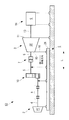
図8は、本発明の第3実施形態を示すコンバインド発電装置の側面図である。このコンバインド発電装置50は、第1および第2実施形態のコンバインド発電装置30,40とは異なる相対移動構造Bを備えている。
[Third Embodiment]
FIG. 8 is a side view of a combined power generation apparatus showing a third embodiment of the present invention. This combined
相対移動構造Bは、蒸気タービン3の熱膨張起点11と熱膨張移動点15との、軸方向Lに沿う位置関係が、第1および第2実施形態のコンバインド発電装置30,40の相対移動構造Aとは逆になっている。つまり、熱膨張移動点15がクラッチ装置7の側に向けられている。
In the relative movement structure B, the positional relationship between the thermal expansion start
基礎部1の上面には、移動台座25が軸方向Lに移動可能に設置されている。この移動台座25は、第1実施形態における移動台座17(図2参照)よりも軸方向Lに沿って長いものとなっているが、基礎部1の上面に段付きボルト18で設置される構成(図4参照)や、基礎部1に対してキー溝20とキー21とを用いて軸方向Lに沿って移動できるようにされる構成等は、第1実施形態と同様である。
A
そして、この移動台座25の上に、蒸気タービン3の熱膨張移動点15が支持部16を介して固定されている。蒸気タービン3の熱膨張起点11は基礎部1の上面に固定されている。また、クラッチ装置7と、減速装置10とが移動台座25の上に設置されている。そして、これらの各部材15,7,10が移動台座25と共に基礎部1の上面を軸方向Lに沿って移動できるようになっている。一方、パワータービン2は移動台座25の上ではなく、基礎部1の上面に固定されている。
A thermal
このように構成されたコンバインド発電装置50において、蒸気タービン3が軸方向Lに沿って熱膨張すると、蒸気タービン3の熱膨張起点11は基礎部1に対して不動である一方、熱膨張移動点15、クラッチ装置7、減速装置10等が、移動台座25と一体となって軸方向Lに沿って蒸気タービン3から離れる方向に移動する。そして、この移動が撓み継手8によって吸収される。このため、熱膨張移動点15とクラッチ装置7との間に相対移動が発生せず、熱膨張による応力がクラッチ装置7に及ばない。
In the combined
したがって、蒸気タービン3とクラッチ装置7との間に撓み継手を設ける必要がなく、このように撓み継手を削減できることから、コンバインド発電装置50を軸方向に短縮し、小型化およびアライメント精度の向上を図るとともに、その建設コストを削減することができる。また、蒸気タービン3と発電機14との間を接続する軸13には蒸気タービン3の熱膨張が及ばないため、図2に示すような伸縮可能なカップリングを省略することができる。
Therefore, there is no need to provide a flexible joint between the
〔第4実施形態〕
図9は、本発明の第4実施形態を示すコンバインド発電装置の側面図である。このコンバインド発電装置60は、第3実施形態のコンバインド発電装置50に比べて、その移動台座26の軸方向Lに沿う寸法が、第3実施形態の移動台座25よりも長くなっている。
[Fourth Embodiment]
FIG. 9 is a side view of a combined power generation apparatus showing a fourth embodiment of the present invention. Compared with the combined
第3実施形態では、移動台座25の上に蒸気タービン3の熱膨張移動点15とクラッチ装置7とパワータービン2減速装置10等が設置されていたが、この第4実施形態においては、パワータービン2と撓み継手8も移動台座26の上面に設置されている。その他の構成は第3実施形態と同様である。
In the third embodiment, the thermal
このコンバインド発電装置60において、蒸気タービン3が熱膨張すると、その熱膨張移動点15とクラッチ装置7と減速装置10と撓み継手8とパワータービン2とが移動台座26と共に軸方向Lに沿って移動する。このため、蒸気タービン3の熱膨張による応力がクラッチ装置7およびパワータービン2に加わらない。
In this combined
したがって、第3実施形態と同様に、蒸気タービン3とクラッチ装置7との間に撓み継手を設ける必要がなく、コンバインド発電装置60を従来よりも軸方向に短縮し、小型化およびアライメント精度の向上を図るとともに、その建設コストを削減することができる。
Therefore, as in the third embodiment, there is no need to provide a flexible joint between the
特に、蒸気タービン3の熱膨張移動点15とパワータービン2とが移動台座26の上に固定されていて互いに相対移動しないため、パワータービン2の熱膨張を吸収するための撓み継手8が、蒸気タービン3の熱膨張の影響を受けない。このため、撓み継手8の熱伸び吸収量を、第3実施形態のコンバインド発電装置50と比較して小さくして、撓み継手8を比較的簡易(安価)な構造のものにすることができる。
In particular, since the thermal
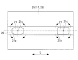
しかしながら、移動台座26の上に設置される機材類の重量が大きくなることから、移動台座26が基礎部1の上をスムーズにスライドしない場合がある。これを解決するべく、図10に示すように、キー21は、その長さが移動台座17の軸方向Lに沿う寸法よりも格段に短くされるとともに、キー溝20の内部で微小角度の回動が可能な回転中心21cを備え、軸方向Lに沿って離間して複数個配置されている。
However, since the weight of the equipment installed on the
より具体的には、各キー21は、平面視で、その四隅に面取り21a、もしくはR面取り21bが施されており、キー溝20の内部で回転中心21cを中心に僅かに回動することができる。そして、このようなキー21が、キー溝20の内部に複数個、軸方向Lに沿って離間して配置されている。キー溝20とキー21との間には、グリス等の高粘度な液体を封入しておくのが好ましい。なお、キー溝20は、移動台座17の全長に亘って形成してもよいが、図11に示すように、キー21を嵌合できるだけの短いキー溝20を軸方向Lに沿って分散させて形成してもよい。
More specifically, each key 21 has
このようなキー21を介して移動台座26を基礎部1の上に設置することにより、移動台座26の重量が大きくても、基礎部1の上をスムーズにスライドさせることができる。また、蒸気タービン3の熱を受けて移動台座26やキー溝20、キー21等が熱膨張して僅かに変形したとしても、各キー21がキー溝20の内部で微小角度回動することにより、上記の熱変形が吸収される。したがって、簡素な構造により、コンバインドサイクル発電装置60のアライメント精度を向上させることができる。
By installing the
なお、上記のように、キー21に、キー溝20の内部で微小角度の回動が可能な回転中心21cを設けることは、第1〜第3実施形態のコンバインド発電装置30,40,50にも適用することができる。
As described above, providing the key 21 with the
〔第5実施形態〕
図12は、本発明の第5実施形態を示すコンバインド発電装置の側面図であり、図13は同じく平面図である。このコンバインド発電装置70は、図2に示す第1実施形態のコンバインド発電装置30を変形させたものである。即ち、第1実施形態のコンバインド発電装置30では、パワータービン2と蒸気タービン3とが直列に配置された構成であったが、このコンバインド発電装置70は、パワータービン2と蒸気タービン3とが並列に配置されている。その他の構成は第1実施形態のコンバインド発電装置30と同一であるため、各部に同一符号を付して説明を省略する。
[Fifth Embodiment]
FIG. 12 is a side view of a combined power generation apparatus showing a fifth embodiment of the present invention, and FIG. 13 is a plan view of the same. This combined
このように、構成されたコンバインド発電装置70は、第1実施形態のコンバインド発電装置30と同様に、蒸気タービン3の熱膨張による軸方向Lへの熱伸びが移動台座17の移動により吸収されるため、蒸気タービン3とクラッチ装置7との間に撓み継手を設けなくてもよく、これにより蒸気タービン3とクラッチ装置7との間の軸長を短くすることができる。そして、パワータービン2と蒸気タービン3とが並列に配置されていることと相まって、コンバインド発電装置70の軸方向Lに沿う寸法を大幅にコンパクト化するとともに、アライメント精度を向上させることができる。
As described above, in the combined
以上のように、本発明に掛かるコンバインド動力装置によれば、タービンの熱膨張による応力がクラッチ装置に及ばないようにして撓み継手の数量を削減し、主に軸方向への小型化と、建設コストの削減、およびアライメント精度の向上を実現することができる。 As described above, according to the combined power device according to the present invention, the number of flexible joints is reduced by preventing the stress due to the thermal expansion of the turbine from reaching the clutch device, and the size and construction in the axial direction are mainly reduced. Cost reduction and improved alignment accuracy can be realized.
また、本発明に掛かるコンバインド動力装置を船舶に搭載することにより、コンバインド動力装置の軸方向寸法が短縮されるため、船体内部のスペース占有率が小さくて済む。その結果、船体内のレイアウト性が良くなり、各部の設計自由度を高めることができる。 Further, by mounting the combined power device according to the present invention on a ship, the axial dimension of the combined power device is shortened, so that the space occupancy rate inside the hull is small. As a result, the layout within the hull is improved, and the degree of freedom in designing each part can be increased.
しかも、コスト的に高価な撓み継手の数量を削減できるため、船体の建造コストを安くすることができる。さらに、コンバインド動力装置の軸方向寸法を短縮できることから、アライメント精度を向上させることができ、これによって回転振動の発生を抑制し、船舶の乗り心地や静粛性を向上させることができる。 Moreover, since the number of costly flexible joints can be reduced, the construction cost of the hull can be reduced. Furthermore, since the axial dimension of the combined power unit can be shortened, the alignment accuracy can be improved, thereby suppressing the occurrence of rotational vibration and improving the ride comfort and quietness of the ship.
なお、本発明は、上記の第1〜第5実施形態の構成のみに限定されるものではなく、本発明の要旨を逸脱しない範囲内において適宜変更や改良を加えることができ、このように変更や改良を加えた実施形態も本発明の権利範囲に含まれるものとする。 Note that the present invention is not limited to the configurations of the first to fifth embodiments described above, and can be appropriately modified or improved without departing from the gist of the present invention. Embodiments with or without modifications are also included in the scope of the right of the present invention.
例えば、上記の各実施形態では、パワータービン2と蒸気タービン3のうち、より熱膨張量の大きい蒸気タービン3に本発明を適用した例について説明したが、パワータービン2についても同様に本発明を適用することができる。
For example, in each of the above-described embodiments, the example in which the present invention is applied to the
1 基礎部
2 パワータービン
3 蒸気タービン
4,5,6 出力軸
7 クラッチ装置
8,9 撓み継手
11 熱膨張起点
14 発電機
15 熱膨張移動点
17,25,26 移動台座
20 キー溝
21 キー
21a 面取り
21b R面取り
21c 回転中心
23 可撓性支持部
30,40,50,60,70 コンバインド発電装置(コンバインド動力装置)
A,B 相対移動構造
L タービンの軸方向
DESCRIPTION OF
A, B Relative structure L Turbine axial direction
Claims (6)
前記パワータービンおよび前記蒸気タービンのうちの、少なくとも熱膨張量の大きいタービンは、その軸方向の一端が熱膨張起点として前記基礎部の上面に固定され、前記軸方向の他端が熱膨張移動点として前記基礎部の上面に対して前記軸方向に移動可能に配置されるとともに、
前記熱膨張移動点の移動による応力が前記クラッチ装置に及ぶことを防止する相対移動構造が設けられていることを特徴とするコンバインド動力装置。 A combined power device in which the output shafts of the power turbine and the steam turbine installed on the upper surface of the base portion can be connected via a clutch device,
Of the power turbine and the steam turbine, at least a turbine having a large thermal expansion amount, one end in the axial direction is fixed to the upper surface of the base portion as a thermal expansion starting point, and the other end in the axial direction is a thermal expansion moving point. And arranged so as to be movable in the axial direction with respect to the upper surface of the base portion,
A combined power device is provided, wherein a relative movement structure is provided to prevent stress due to movement of the thermal expansion movement point from reaching the clutch device.
Priority Applications (5)
| Application Number | Priority Date | Filing Date | Title |
|---|---|---|---|
| JP2013176580A JP2015045262A (en) | 2013-08-28 | 2013-08-28 | Combined power apparatus, and marine vessel mounted with the same |
| EP14839737.5A EP2921660A4 (en) | 2013-08-28 | 2014-08-22 | Combined motive power apparatus and ship equipped with same |
| PCT/JP2014/072000 WO2015029898A1 (en) | 2013-08-28 | 2014-08-22 | Combined motive power apparatus and ship equipped with same |
| KR1020157010691A KR101547451B1 (en) | 2013-08-28 | 2014-08-22 | Combined motive power apparatus and ship equipped with same |
| CN201480002748.3A CN105518259A (en) | 2013-08-28 | 2014-08-22 | Combined motive power apparatus and ship equipped with same |
Applications Claiming Priority (1)
| Application Number | Priority Date | Filing Date | Title |
|---|---|---|---|
| JP2013176580A JP2015045262A (en) | 2013-08-28 | 2013-08-28 | Combined power apparatus, and marine vessel mounted with the same |
Publications (2)
| Publication Number | Publication Date |
|---|---|
| JP2015045262A true JP2015045262A (en) | 2015-03-12 |
| JP2015045262A5 JP2015045262A5 (en) | 2015-04-23 |
Family
ID=52586457
Family Applications (1)
| Application Number | Title | Priority Date | Filing Date |
|---|---|---|---|
| JP2013176580A Pending JP2015045262A (en) | 2013-08-28 | 2013-08-28 | Combined power apparatus, and marine vessel mounted with the same |
Country Status (5)
| Country | Link |
|---|---|
| EP (1) | EP2921660A4 (en) |
| JP (1) | JP2015045262A (en) |
| KR (1) | KR101547451B1 (en) |
| CN (1) | CN105518259A (en) |
| WO (1) | WO2015029898A1 (en) |
Families Citing this family (5)
| Publication number | Priority date | Publication date | Assignee | Title |
|---|---|---|---|---|
| WO2016184678A1 (en) * | 2015-05-15 | 2016-11-24 | General Electric Technology Gmbh | Steam turbine foundation |
| CN109204761A (en) * | 2018-09-26 | 2019-01-15 | 中国船舶重工集团公司第七0三研究所 | A kind of marine engine group modularization integrated stand with steam discharge function |
| CN109878675A (en) * | 2019-02-28 | 2019-06-14 | 哈尔滨工程大学 | A kind of bi-motor coaxial-type pneumoelectric mixing ship power system |
| US11460037B2 (en) | 2019-03-29 | 2022-10-04 | Pratt & Whitney Canada Corp. | Bearing housing |
| CN114607475A (en) * | 2022-04-08 | 2022-06-10 | 哈尔滨汽轮机厂有限责任公司 | 5MW integrated steam turbine generator unit |
Citations (6)
| Publication number | Priority date | Publication date | Assignee | Title |
|---|---|---|---|---|
| JPS60178311U (en) * | 1984-05-04 | 1985-11-27 | 株式会社日立製作所 | combined plant |
| JPH039002A (en) * | 1989-06-05 | 1991-01-16 | Toshiba Corp | Steam turbine in uniaxial combined cycle |
| JPH0337305A (en) * | 1989-07-03 | 1991-02-18 | General Electric Co <Ge> | Mono-axial combined cycle turbine |
| JPH08512380A (en) * | 1994-05-03 | 1996-12-24 | ジエ・ウー・セー・アルストム・エレクトロメカニク・エス・アー | Power generation unit with combined cycle, including gas turbine and steam turbine with multiple modules |
| JP2010121498A (en) * | 2008-11-18 | 2010-06-03 | Mitsubishi Heavy Ind Ltd | Supporting structure of turbine casing |
| JP2010133284A (en) * | 2008-12-02 | 2010-06-17 | Mitsubishi Heavy Ind Ltd | Power generation system |
Family Cites Families (8)
| Publication number | Priority date | Publication date | Assignee | Title |
|---|---|---|---|---|
| US5271217A (en) | 1992-12-09 | 1993-12-21 | General Electric Company | Mounting arrangement for a single shaft combined cycle system |
| FR2702243B1 (en) * | 1993-03-03 | 1995-04-14 | Gec Alsthom Electromec | Power plant with gas turbine and steam turbine. |
| JP2002349289A (en) * | 2001-05-21 | 2002-12-04 | Toshiba Corp | Sole plate for turbine and power generation plant apparatus using the sole plate |
| DE10321026A1 (en) * | 2003-05-10 | 2004-11-25 | Atlas Copco Energas Gmbh | turbomachinery |
| US7267319B2 (en) * | 2004-11-09 | 2007-09-11 | General Electric Company | Low-friction slide-plates for rotary machines |
| EP1764485A1 (en) * | 2005-09-15 | 2007-03-21 | Siemens Aktiengesellschaft | Device for the support of rotary machines of a stationary turboset |
| EP2372127A4 (en) * | 2008-12-26 | 2014-08-13 | Mitsubishi Heavy Ind Ltd | Control device for waste heat recovery system |
| CN102926873A (en) * | 2012-11-28 | 2013-02-13 | 北京华清燃气轮机与煤气化联合循环工程技术有限公司 | Gas turbine support system |
-
2013
- 2013-08-28 JP JP2013176580A patent/JP2015045262A/en active Pending
-
2014
- 2014-08-22 WO PCT/JP2014/072000 patent/WO2015029898A1/en active Application Filing
- 2014-08-22 EP EP14839737.5A patent/EP2921660A4/en not_active Withdrawn
- 2014-08-22 KR KR1020157010691A patent/KR101547451B1/en active IP Right Grant
- 2014-08-22 CN CN201480002748.3A patent/CN105518259A/en active Pending
Patent Citations (6)
| Publication number | Priority date | Publication date | Assignee | Title |
|---|---|---|---|---|
| JPS60178311U (en) * | 1984-05-04 | 1985-11-27 | 株式会社日立製作所 | combined plant |
| JPH039002A (en) * | 1989-06-05 | 1991-01-16 | Toshiba Corp | Steam turbine in uniaxial combined cycle |
| JPH0337305A (en) * | 1989-07-03 | 1991-02-18 | General Electric Co <Ge> | Mono-axial combined cycle turbine |
| JPH08512380A (en) * | 1994-05-03 | 1996-12-24 | ジエ・ウー・セー・アルストム・エレクトロメカニク・エス・アー | Power generation unit with combined cycle, including gas turbine and steam turbine with multiple modules |
| JP2010121498A (en) * | 2008-11-18 | 2010-06-03 | Mitsubishi Heavy Ind Ltd | Supporting structure of turbine casing |
| JP2010133284A (en) * | 2008-12-02 | 2010-06-17 | Mitsubishi Heavy Ind Ltd | Power generation system |
Also Published As
| Publication number | Publication date |
|---|---|
| KR101547451B1 (en) | 2015-08-25 |
| CN105518259A (en) | 2016-04-20 |
| EP2921660A1 (en) | 2015-09-23 |
| WO2015029898A1 (en) | 2015-03-05 |
| KR20150059650A (en) | 2015-06-01 |
| EP2921660A4 (en) | 2015-12-23 |
Similar Documents
| Publication | Publication Date | Title |
|---|---|---|
| WO2015029898A1 (en) | Combined motive power apparatus and ship equipped with same | |
| JP5631660B2 (en) | Turbine system | |
| JP5596109B2 (en) | Gas turbine engine | |
| US20190316846A1 (en) | Waste heat recovery and conversion system and related methods | |
| US10982713B2 (en) | Closed cycle heat engine | |
| KR20090087091A (en) | Exhaust gas turbocharger | |
| EP3080405B1 (en) | Gas turbine offshore installations | |
| JP2012092653A (en) | Power generation system | |
| JP6257965B2 (en) | Foil bearing unit | |
| JP2011190802A (en) | Pressure wave supercharger | |
| US10364038B2 (en) | Propulsion unit for an aircraft | |
| CN205674866U (en) | Auxiliary power of car system and new-energy automobile | |
| IT201600127545A1 (en) | Mounting system for rotating machines | |
| JP6000077B2 (en) | Exhaust turbine support structure | |
| CN105437967A (en) | Automobile auxiliary power system and new energy automobile | |
| JP2011208622A (en) | Surplus exhaust energy recovery device for internal combustion engine | |
| JP2001317376A (en) | Auxiliary machine driving unit for gas turbine engine | |
| WO2024083252A1 (en) | Parallel-stage medium-speed shaft system connecting structure for wind turbine, and shaft system | |
| US11603890B2 (en) | Driveline engagement system | |
| Brun et al. | A novel centrifugal flow gas turbine design | |
| WO2021049051A1 (en) | Gas turbine | |
| WO2018150770A1 (en) | Intake air cooling system and pressure transmission device | |
| JPH0574518B2 (en) | ||
| JP4418417B2 (en) | Ship propulsion device with turbine as a high temperature drive source |
Legal Events
| Date | Code | Title | Description |
|---|---|---|---|
| A521 | Written amendment |
Free format text: JAPANESE INTERMEDIATE CODE: A523 Effective date: 20150226 |
|
| A621 | Written request for application examination |
Free format text: JAPANESE INTERMEDIATE CODE: A621 Effective date: 20150226 |
|
| A131 | Notification of reasons for refusal |
Free format text: JAPANESE INTERMEDIATE CODE: A131 Effective date: 20151104 |
|
| A521 | Written amendment |
Free format text: JAPANESE INTERMEDIATE CODE: A523 Effective date: 20160104 |
|
| A131 | Notification of reasons for refusal |
Free format text: JAPANESE INTERMEDIATE CODE: A131 Effective date: 20160524 |
|
| A02 | Decision of refusal |
Free format text: JAPANESE INTERMEDIATE CODE: A02 Effective date: 20161122 |