JP2015030421A - Vehicle heating device - Google Patents
Vehicle heating device Download PDFInfo
- Publication number
- JP2015030421A JP2015030421A JP2013163046A JP2013163046A JP2015030421A JP 2015030421 A JP2015030421 A JP 2015030421A JP 2013163046 A JP2013163046 A JP 2013163046A JP 2013163046 A JP2013163046 A JP 2013163046A JP 2015030421 A JP2015030421 A JP 2015030421A
- Authority
- JP
- Japan
- Prior art keywords
- air
- heat exchanger
- vehicle
- heat
- outside
- Prior art date
- Legal status (The legal status is an assumption and is not a legal conclusion. Google has not performed a legal analysis and makes no representation as to the accuracy of the status listed.)
- Withdrawn
Links
Images


Classifications
-
- B—PERFORMING OPERATIONS; TRANSPORTING
- B60—VEHICLES IN GENERAL
- B60H—ARRANGEMENTS OF HEATING, COOLING, VENTILATING OR OTHER AIR-TREATING DEVICES SPECIALLY ADAPTED FOR PASSENGER OR GOODS SPACES OF VEHICLES
- B60H1/00—Heating, cooling or ventilating [HVAC] devices
- B60H1/02—Heating, cooling or ventilating [HVAC] devices the heat being derived from the propulsion plant
- B60H1/025—Heating, cooling or ventilating [HVAC] devices the heat being derived from the propulsion plant from both the cooling liquid and the exhaust gases of the propulsion plant
-
- B—PERFORMING OPERATIONS; TRANSPORTING
- B60—VEHICLES IN GENERAL
- B60H—ARRANGEMENTS OF HEATING, COOLING, VENTILATING OR OTHER AIR-TREATING DEVICES SPECIALLY ADAPTED FOR PASSENGER OR GOODS SPACES OF VEHICLES
- B60H1/00—Heating, cooling or ventilating [HVAC] devices
- B60H1/02—Heating, cooling or ventilating [HVAC] devices the heat being derived from the propulsion plant
- B60H1/14—Heating, cooling or ventilating [HVAC] devices the heat being derived from the propulsion plant otherwise than from cooling liquid of the plant, e.g. heat from the grease oil, the brakes, the transmission unit
- B60H1/18—Heating, cooling or ventilating [HVAC] devices the heat being derived from the propulsion plant otherwise than from cooling liquid of the plant, e.g. heat from the grease oil, the brakes, the transmission unit the air being heated from the plant exhaust gases
- B60H1/20—Heating, cooling or ventilating [HVAC] devices the heat being derived from the propulsion plant otherwise than from cooling liquid of the plant, e.g. heat from the grease oil, the brakes, the transmission unit the air being heated from the plant exhaust gases using an intermediate heat-transferring medium
-
- B—PERFORMING OPERATIONS; TRANSPORTING
- B60—VEHICLES IN GENERAL
- B60H—ARRANGEMENTS OF HEATING, COOLING, VENTILATING OR OTHER AIR-TREATING DEVICES SPECIALLY ADAPTED FOR PASSENGER OR GOODS SPACES OF VEHICLES
- B60H1/00—Heating, cooling or ventilating [HVAC] devices
- B60H1/00007—Combined heating, ventilating, or cooling devices
- B60H1/00021—Air flow details of HVAC devices
- B60H1/00028—Constructional lay-out of the devices in the vehicle
-
- B—PERFORMING OPERATIONS; TRANSPORTING
- B60—VEHICLES IN GENERAL
- B60H—ARRANGEMENTS OF HEATING, COOLING, VENTILATING OR OTHER AIR-TREATING DEVICES SPECIALLY ADAPTED FOR PASSENGER OR GOODS SPACES OF VEHICLES
- B60H1/00—Heating, cooling or ventilating [HVAC] devices
- B60H1/00507—Details, e.g. mounting arrangements, desaeration devices
- B60H1/00557—Details of ducts or cables
- B60H1/00564—Details of ducts or cables of air ducts
-
- B—PERFORMING OPERATIONS; TRANSPORTING
- B60—VEHICLES IN GENERAL
- B60H—ARRANGEMENTS OF HEATING, COOLING, VENTILATING OR OTHER AIR-TREATING DEVICES SPECIALLY ADAPTED FOR PASSENGER OR GOODS SPACES OF VEHICLES
- B60H1/00—Heating, cooling or ventilating [HVAC] devices
- B60H1/00642—Control systems or circuits; Control members or indication devices for heating, cooling or ventilating devices
- B60H1/00664—Construction or arrangement of damper doors
- B60H1/00671—Damper doors moved by rotation; Grilles
- B60H1/00678—Damper doors moved by rotation; Grilles the axis of rotation being in the door plane, e.g. butterfly doors
-
- B—PERFORMING OPERATIONS; TRANSPORTING
- B60—VEHICLES IN GENERAL
- B60H—ARRANGEMENTS OF HEATING, COOLING, VENTILATING OR OTHER AIR-TREATING DEVICES SPECIALLY ADAPTED FOR PASSENGER OR GOODS SPACES OF VEHICLES
- B60H1/00—Heating, cooling or ventilating [HVAC] devices
- B60H1/02—Heating, cooling or ventilating [HVAC] devices the heat being derived from the propulsion plant
- B60H1/03—Heating, cooling or ventilating [HVAC] devices the heat being derived from the propulsion plant and from a source other than the propulsion plant
- B60H1/039—Heating, cooling or ventilating [HVAC] devices the heat being derived from the propulsion plant and from a source other than the propulsion plant from air leaving the interior of the vehicle, i.e. heat recovery
-
- B—PERFORMING OPERATIONS; TRANSPORTING
- B60—VEHICLES IN GENERAL
- B60H—ARRANGEMENTS OF HEATING, COOLING, VENTILATING OR OTHER AIR-TREATING DEVICES SPECIALLY ADAPTED FOR PASSENGER OR GOODS SPACES OF VEHICLES
- B60H1/00—Heating, cooling or ventilating [HVAC] devices
- B60H1/02—Heating, cooling or ventilating [HVAC] devices the heat being derived from the propulsion plant
- B60H1/14—Heating, cooling or ventilating [HVAC] devices the heat being derived from the propulsion plant otherwise than from cooling liquid of the plant, e.g. heat from the grease oil, the brakes, the transmission unit
-
- F—MECHANICAL ENGINEERING; LIGHTING; HEATING; WEAPONS; BLASTING
- F01—MACHINES OR ENGINES IN GENERAL; ENGINE PLANTS IN GENERAL; STEAM ENGINES
- F01N—GAS-FLOW SILENCERS OR EXHAUST APPARATUS FOR MACHINES OR ENGINES IN GENERAL; GAS-FLOW SILENCERS OR EXHAUST APPARATUS FOR INTERNAL COMBUSTION ENGINES
- F01N5/00—Exhaust or silencing apparatus combined or associated with devices profiting from exhaust energy
- F01N5/02—Exhaust or silencing apparatus combined or associated with devices profiting from exhaust energy the devices using heat
-
- Y—GENERAL TAGGING OF NEW TECHNOLOGICAL DEVELOPMENTS; GENERAL TAGGING OF CROSS-SECTIONAL TECHNOLOGIES SPANNING OVER SEVERAL SECTIONS OF THE IPC; TECHNICAL SUBJECTS COVERED BY FORMER USPC CROSS-REFERENCE ART COLLECTIONS [XRACs] AND DIGESTS
- Y02—TECHNOLOGIES OR APPLICATIONS FOR MITIGATION OR ADAPTATION AGAINST CLIMATE CHANGE
- Y02T—CLIMATE CHANGE MITIGATION TECHNOLOGIES RELATED TO TRANSPORTATION
- Y02T10/00—Road transport of goods or passengers
- Y02T10/10—Internal combustion engine [ICE] based vehicles
- Y02T10/12—Improving ICE efficiencies
Abstract
Description
本発明は、排気ガスの熱を利用する車両用暖房装置に関する。 The present invention relates to a vehicle heating device that uses the heat of exhaust gas.
従来、車両のエンジンから排出される高温の排気ガスを利用して、車室内の暖房を効率的に行うことが検討されている。このような技術として、例えば、特許文献1に開示の暖房装置が知られている。
Conventionally, it has been studied to efficiently heat a passenger compartment by using high-temperature exhaust gas discharged from a vehicle engine. As such a technique, for example, a heating device disclosed in
特許文献1には、エンジンの排気通路の排気ガス浄化触媒の下流に熱交換器を設けて高温の排気ガスと低温の外気との間で熱交換する暖房装置が開示されている。これにより、排気ガス浄化触媒で発生した反応熱を有効に利用して熱交換効率を高めることができる。
また、特許文献1に開示の暖房装置では、熱交換器が破損して排気ガスが外気供給通路内に流入すると、高温の外気と低温の外気を混合する第1ミキシングバルブを閉じて、熱交換器との連通を遮断することで、排気ガスが車室内に流入するのを防止することができる。
Further, in the heating device disclosed in
さらに、特許文献1に開示の暖房装置では、第1熱交換器と第2熱交換器を備え、第1熱交換器と第2熱交換器とを、空気などの媒体が循環する循環通路によって接続し、第1熱交換器で高温の排気ガスと循環通路内の媒体との間で熱交換を行って媒体を加熱し、第2熱交換器で高温の媒体と低温の外気との間で熱交換を行って外気を加熱する。
Furthermore, the heating device disclosed in
しかしながら、上述した特許文献1に開示の暖房装置では、第1熱交換器が仮に破損した場合、循環通路に排気ガスが混合する。特許文献1に開示の暖房装置では、循環通路を有するため、この排気ガスが混合した空気は外部に排出されず循環し続ける。この結果、排気ガスに含まれる物質が循環通路内に蓄積することで、熱交換効率が低下してしまう、という問題がある。
However, in the heating device disclosed in
本発明の目的は、熱交換効率の低下を防止する車両用暖房装置を提供することである。 The objective of this invention is providing the heating apparatus for vehicles which prevents the fall of heat exchange efficiency.
本発明の一態様に係る車両用暖房装置は、エンジンから排出される排気ガスと、車室外または車室内から導入された第1空気との間で熱交換を行う第1熱交換器と、前記第1熱交換器にて前記排気ガスと熱交換された前記第1空気と、車室外から取り込まれた第2空気との間で熱交換し、熱交換された前記第1空気を車室外に排気し、熱交換された前記第2空気を車室内に供給する第2熱交換器と、を具備する構成を採る。 A vehicle heating device according to an aspect of the present invention includes a first heat exchanger that exchanges heat between exhaust gas discharged from an engine and first air introduced from the outside of the vehicle compartment or from the vehicle interior, Heat exchange is performed between the first air heat-exchanged with the exhaust gas in the first heat exchanger and the second air taken from outside the vehicle compartment, and the heat-exchanged first air is outside the vehicle compartment. And a second heat exchanger that supplies the second air that has been exhausted and heat-exchanged to the vehicle interior.
本発明によれば、車室外または車室内から導入された第1空気は、熱交換された後、車室外に排気されるので、熱交換効率の低下を防止することができる。 According to the present invention, the first air introduced from the outside of the passenger compartment or the passenger compartment is exhausted to the outside of the passenger compartment after being subjected to heat exchange, so that a reduction in heat exchange efficiency can be prevented.
以下、本発明の実施の形態について、図面を参照して詳細に説明する。ただし、実施の形態において、同一の構成には同一の符号を付し、重複する説明は省略する。 Hereinafter, embodiments of the present invention will be described in detail with reference to the drawings. However, in the embodiments, the same components are denoted by the same reference numerals, and redundant description is omitted.
(実施の形態1)
<空調システムの構成>
図1は、本発明の実施の形態1に係る空調システム10の概略構成を示す図である。図中、実線の矢印が排気ガスの流れを示し、点線の矢印が外気の流れを示している。
(Embodiment 1)
<Configuration of air conditioning system>
FIG. 1 is a diagram showing a schematic configuration of an
エンジン11は、揮発性の高い燃料(ガソリンまたは軽油など)と空気とを混合し、これを燃焼させることによって、動力を発生する。エンジン11は、燃焼によって生じた排気ガスを排気通路12に排出する。
The
触媒13は、排気通路12に設けられており、プラチナ、パラジウム、ロジウム等からなり、エンジン11から排出された排気ガスに含まれる有害成分(主に、炭化水素、一酸化炭素、窒素酸化物)を酸化または還元によって浄化し、浄化した排気ガスを熱交換器14に排出する。触媒13では、酸化還元反応により高温の反応熱が発生する。
The
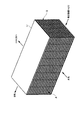
熱交換器14(第1熱交換器に相当)は、例えば、ステンレスからなり、触媒13下流側の排気通路12に設けられる。また、熱交換器14は、図2に示すように、排気通路12と、外気を導入する第1空気通路15とが熱交換可能に接しており、排気ガスと外気とが混合しない構成となっている。熱交換器14は、排気ガスと外気との間で熱交換を行い、高温の排気ガスから低温の外気へ放熱させる。熱交換器14から排出された排気ガスは、車外に排気され、熱交換器14から排出された外気はブロア16を経由して顕熱交換器17に供給される。
The heat exchanger 14 (corresponding to the first heat exchanger) is made of stainless steel, for example, and is provided in the
ブロア16は、熱交換器14と顕熱交換器17とを繋ぐ第1空気通路15に設けられ、熱交換器14において加熱された外気を吸入し、吸入した外気を顕熱交換器17に送風する。
The
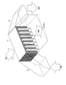
顕熱交換器17(第2熱交換器に相当)は、例えば、アルミまたはポリプロピレンからなり、図3に示すように、流路が固定された静止型の熱交換器である。顕熱交換器17は、隣接する2系統の流路A,Bを有し、一方の流路Aに低温の外気を流し、他方の流路Bに高温の外気を流す。それにより、顕熱交換器17では、流路Aと流路Bとの空気を混合せずに流路Bの空気の熱を流路Aの空気へ移動させることができる。各系統の流路A,Bには多数の細かい流路が設けられ、各系統の細かい流路を互いに交差させて配置することで2系統の流路A,Bの接触面積を大きくしている。
The sensible heat exchanger 17 (corresponding to the second heat exchanger) is made of, for example, aluminum or polypropylene, and is a stationary heat exchanger with a flow path fixed as shown in FIG. The
顕熱交換器17には、低温の外気の通路である第2空気通路18が流路Aの一端と他端とにそれぞれ接続されている。また、顕熱交換器17には、第1空気通路15が流路Bの一端と他端とにそれぞれ接続されている。
The
上記のような顕熱交換器17と各通路との接続により、顕熱交換器17の流路Aに車外から導入される低温の外気が通り、顕熱交換器17の流路Bに熱交換器14において加熱された高温の外気が通る。そして、顕熱交換器17において、高温の外気から低温の外気へ熱が移動して、排気の熱回収が行われる。
By connecting the
HVAC(Heating, Ventilation, and Air Conditioning)20は、エンジンルームと車室内とを区切る図示せぬ隔壁(ファイアウォール)の車室側に配置され、送風用のブロア21と、このブロア21の送風路中に上流側から下流側に順次配設されている、ヒートポンプサイクルを構成する冷房用空気冷媒熱交換器22及び暖房用空気冷媒熱交換器23と、切換ドア24とを備え、冷房用空気冷媒熱交換器22及び暖房用空気冷媒熱交換器23によって温調された空気を車室内に吹き出し、車室内の空調を行う。
An HVAC (Heating, Ventilation, and Air Conditioning) 20 is disposed on the passenger compartment side of a partition wall (firewall) (not shown) that separates the engine room and the passenger compartment, and a
このように、空調システム10は、第1空気通路15の吸入口から吸入された外気は熱交換された後、車室外に排気することにより、熱交換器14が破損した場合でも、排気ガスが混合した空気を循環させずに車室外に排気することができる。また、空調システム10は、熱交換器14において、排気ガスと外気との熱交換を行い、さらに、顕熱交換器17において、加熱された高温の外気と低温の外気との熱交換を行うという2段階の熱交換により、熱交換器14が破損した場合でも、排気ガスが車室内に流入することを防止することができる。また、排気通路12に排気ガス濃度を検出する手段及び排気ガスの流入を遮断する装置を設ける必要がないので、空調システム10のメンテナスを容易に行うことができる。
As described above, the
<空調システムの車両搭載配置>
図4は、図1に示した空調システム10を車両に搭載した様子を示す概略図である。図4に示すように、第1空気通路15の吸入口は、開口部が車両後方を向き、車両底部に設けられ、ブロア16によって吸入口から外気が吸入される。一方、第1空気通路15の排出口は、車両の床下に設けられ、排出口から排出された高温の外気は、走行中にタイヤの回転が生み出す空気の流れに導かれる。
<Vehicle placement of air conditioning system>
FIG. 4 is a schematic diagram showing a state where the
また、第2空気通路18の吸入口は、一般的には、フロントガラス前方にあるカウルトップ下部に設けられており、既存の空気吸入口(HVACの外気吸入口)である。一方、第2空気通路18の排出口は、HVAC20のブロア21に直結している(図1参照)。
Further, the suction port of the
<顕熱交換器の車両搭載配置>
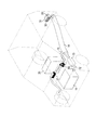
図5は、図1に示した空調システム10を車両に搭載した様子を車両の前方斜め上方から見た斜視図であり、図6は、車両の側方から見た側面図である。
<Vehicle placement of sensible heat exchanger>
FIG. 5 is a perspective view of the air-
これらの図から分かるように、顕熱交換器17は、流路Aが車両の前後方向を向き、流路Bが車両の左右方向を向くように配置される。また、顕熱交換器17は、フロントガラス前方にあるカウルトップの下部にある、外気が導入されるインテークダクトの内部に配設される。これにより、顕熱交換器17が排気通路12から離れて配置されるため、きれいな外気を車室内に取り入れることができる。
As can be seen from these drawings, the
<実施の形態1の効果>
実施の形態1では、第1空気通路15の吸入口から吸入された外気は熱交換された後、車室外に排気される。この結果、熱交換器14が破損した場合でも、排気ガスが混合した空気は循環せずに車室外に排気される。以上のように、実施の形態1によれば、排気ガスに含まれる物質が第1空気通路15内に蓄積することはなく、熱交換効率の低下を防止することができる。
<Effect of
In the first embodiment, the outside air sucked from the suction port of the
さらに、排気ガスに含まれる物質が第1空気通路15内に蓄積することがないため、熱交換器14が破損した場合でも、排気ガスによる第1空気通路15を構成する配管の劣化を防止することも可能となる。
Further, since substances contained in the exhaust gas do not accumulate in the
また、実施の形態1によれば、排気ガスと外気との熱交換を行う熱交換器14と、熱交換器14において加熱された高温の外気と車室内に導入する低温の外気との熱交換を行う顕熱交換器17とを備えることにより、熱交換器14が破損した場合でも、排気ガスの車室内への流入を防止することができる。
Further, according to the first embodiment, the
また、第1空気通路15は循環通路となっていないことで、第1熱交換器と第2熱交換器とを離れた位置に配置しても第1空気通路15を構成する配管を少なくできるため、これらの配置に自由度を持たせることが可能となる。
In addition, since the
また、顕熱交換器17を排気通路12から離れて配置することにより、きれいな外気を車室内に取り入れることができる。
Further, by arranging the
さらに、排気通路12に排気ガス濃度を検出する手段及び排気ガスの流入を遮断する装置を設ける必要がないので、空調システム10のメンテナスを容易に行うことができる。
Furthermore, since it is not necessary to provide the
なお、本実施の形態では、顕熱交換器を、図3に示すように、直交流式の場合を例に説明したが、本発明はこれに限るものではない。例えば、図7に示すように、対向流式の顕熱交換器でもよい。 In the present embodiment, the sensible heat exchanger has been described by taking the case of a cross flow type as shown in FIG. 3, but the present invention is not limited to this. For example, as shown in FIG. 7, a counter-flow sensible heat exchanger may be used.
(実施の形態2)
実施の形態1では、熱交換器と顕熱交換器とを繋ぐ第1空気通路吸入口の開口部を車両後方に向けて設ける場合について説明したが、本発明の実施の形態2では、この第1空気通路吸入口の開口部を車両前方に向けて設ける場合について説明する。
(Embodiment 2)
In the first embodiment, the case where the opening portion of the first air passage inlet that connects the heat exchanger and the sensible heat exchanger is provided toward the rear of the vehicle has been described. In the second embodiment of the present invention, The case where the opening part of 1 air passage inlet is provided toward the vehicle front is demonstrated.
図8は、本発明の実施の形態2に係る空調システム30の概略構成を示す図である。図8が図1と異なる点は、ブロア16を削除した点であり、その他の構成は図1と同様である。
FIG. 8 is a diagram showing a schematic configuration of an
図9は、図8に示した空調システム30を車両に搭載した様子を示す概略図であり、図10は、図8に示した空調システム30を車両に搭載した様子を車両の前方斜め上方から見た斜視図である。
FIG. 9 is a schematic diagram illustrating a state in which the
これらの図が示すように、第1空気通路15の吸入口は、開口部を車両前方に向けて、車両底部に設けられ、車両の走行によって吸入口から外気が吸入される。これにより、第1空気通路15内にブロアを設ける必要がなくなり、装置規模の削減及びコスト削減を図ることができる。
As shown in these figures, the suction port of the
なお、第1空気通路15の吸入口は、開口部が車両前方を向いていると、タイヤが巻き上げた泥、水、雪などを吸い込み、詰まってしまうおそれがある。このため、開口部にフィルターを設けたり、開口部の前方に遮蔽板等を配置したりする必要がある。
If the opening of the
<実施の形態2の効果>
このように、実施の形態2によれば、熱交換器14と顕熱交換器17とを繋ぐ第1空気通路吸入口の開口部を車両前方に向けて設けることにより、車両の走行によって吸入口から外気を吸入することができるため、第1空気通路15内にブロアを設ける必要がなく、装置規模の削減及びコスト削減を図ることができる。
<Effect of Embodiment 2>
As described above, according to the second embodiment, by providing the opening of the first air passage suction port that connects the
(実施の形態3)
実施の形態1では、熱交換器に外気を導入する場合について説明したが、本発明の実施の形態3では、熱交換器に導入する空気を外気と車室内の内気とで切り替える場合について説明する。
(Embodiment 3)
In the first embodiment, the case where outside air is introduced into the heat exchanger has been described, but in the third embodiment of the present invention, the case where the air introduced into the heat exchanger is switched between outside air and inside air in the vehicle interior will be described. .
図11は、本発明の実施3に係る空調システム40の概略構成を示す図である。図11が図1と異なる点は、第1空気通路15の吸入口から吸入する空気を外気と車室内の内気とで切り替える外気内気切り替え器31を追加した点であり、その他の構成は図1と同様である。
FIG. 11 is a diagram showing a schematic configuration of an
図12は、図11に示した空調システム40を車両に搭載した様子を示す概略図である。熱交換器14は、触媒13下流側の排気通路12全域にわたって設けられており、第1空気通路15の吸入口は、排気通路12の排出口付近に設けられる。
FIG. 12 is a schematic diagram showing a state where the
外気内気切り替え器31は、第1空気通路15の吸入口に設けられる。また、内気外気切り替え器31は、図13に示すように、内気吸入口32と外気吸入口33とを備え、内気吸入口32と外気吸入口33の開度を切り替える。内気吸入口32は、既存の空気(内気)排出口(例えば、リアピラー付近、テールランプのドラフタ付近など)と接続し、内気を吸入する。また、外気吸入口33は、車両後方から外気を吸入する。
The outside air / inside
外気内気切り替え器31は、低温でのエンジン起動時には内気を吸入し、エンジン温度が一定温度に達した場合には外気を吸入する。これにより、低温でのエンジン起動時に即暖性及び熱効率を向上させることができ、エンジン温度が一定温度に達した場合には外気が高温になりすぎるのを抑制し、温度を調整しやすくできる。
The outside air / inside
<実施の形態3の効果>
このように、実施の形態3によれば、熱交換器14と顕熱交換器17とを繋ぐ第1空気通路15の吸入口から吸入する空気を外気と内気とで切り替える外気内気切り替え器31を設け、低温でのエンジン起動時には内気を吸入することにより、即暖性を向上させ、エンジン温度が一定温度に達した場合には外気を吸入することにより、外気が高温になりすぎるのを抑制し、温度を調整しやすくできる。
<Effect of Embodiment 3>
As described above, according to the third embodiment, the outside air / inside
(実施の形態4)
実施の形態1では、熱交換器に外気を導入する場合について説明したが、本発明の実施の形態4では、熱交換器に導入する空気を車室内の内気とする場合について説明する。
(Embodiment 4)
In the first embodiment, the case where outside air is introduced into the heat exchanger has been described. In the fourth embodiment of the present invention, the case where the air introduced into the heat exchanger is used as the inside air in the vehicle interior will be described.
図14は、本発明の実施4に係る空調システム50の概略構成を示す図である。図14が図1と異なる点は、第1空気通路15の吸入口に吸入する空気を車室内の内気とする点であり、その他の構成は図8と同様である。
FIG. 14 is a diagram showing a schematic configuration of an
図15は、図14に示した空調システム50を車両に搭載した様子を示す概略図である。熱交換器14は、触媒13下流側の排気通路12全域にわたって設けられている。
FIG. 15 is a schematic diagram showing a state where the
第1空気通路15は、内気吸入口32を備え、内気吸入口32が排気通路12の排出口付近に設けられる。内気吸入口32は、既存の空気(内気)排出口(例えば、リアピラー付近、テールランプのドラフタなど)と接続し、内気を吸入する。これにより、低温の外気を吸入する場合に比べ、即暖性と熱効率を向上させることができる。
The
<実施の形態4の効果>
このように、実施の形態4によれば、熱交換器14と顕熱交換器17とを繋ぐ第1空気通路15の内気吸入口32から内気を吸入することにより、低温の外気を吸入する場合に比べ、即暖性と熱効率を向上させることができる。
<Effect of Embodiment 4>
As described above, according to the fourth embodiment, when the outside air is sucked from the
(他の実施の形態)
上述した各実施の形態における顕熱交換器17には、図16に示すように、熱を蓄える蓄熱材51を設けてもよい。図16では、顕熱交換器17の車室内への吹き出し口に複数の蓄熱材51を縦方向に配列し、顕熱交換器17によって加熱された外気の熱を蓄える。なお、蓄熱材51は、空気の流れを妨げないように設けられる。
(Other embodiments)
As shown in FIG. 16, the
これにより、エンジン再起動時など排気ガスが十分な温度に達していない場合でも、蓄熱材51に蓄えられた熱を利用することができ、即暖性を向上させることができる。
Thereby, even when the exhaust gas does not reach a sufficient temperature, such as when the engine is restarted, the heat stored in the
本発明にかかる車両用暖房装置は、ガソリンエンジンまたはディーゼルエンジン等の内燃機関を有する車両に適用できる。 The vehicle heating device according to the present invention can be applied to a vehicle having an internal combustion engine such as a gasoline engine or a diesel engine.
11 エンジン
12 排気通路
13 触媒
14 熱交換器
15 第1空気通路
16、21 ブロア
17 顕熱交換器
20 HVAC
22 冷房用空気冷媒熱交換器
23 暖房用空気冷媒熱交換器
24 切換ドア
31 外気内気切り替え器
32 内気吸入口
33 外気吸入口
51 蓄熱材
11
22 Cooling Air
Claims (8)
前記第1熱交換器にて前記排気ガスと熱交換された前記第1空気と、車室外から取り込まれた第2空気との間で熱交換し、熱交換された前記第1空気を車室外に排気し、熱交換された前記第2空気を車室内に供給する第2熱交換器と、
を具備する車両用暖房装置。 A first heat exchanger that exchanges heat between exhaust gas exhausted from the engine and first air introduced from outside or inside the vehicle compartment;
Heat exchange is performed between the first air heat-exchanged with the exhaust gas in the first heat exchanger and the second air taken in from outside the vehicle compartment, and the heat-exchanged first air is outside the vehicle compartment. A second heat exchanger that supplies the second air that has been exhausted and heat-exchanged into the passenger compartment, and
A vehicle heating apparatus comprising:
請求項1に記載の車両用暖房装置。 The second heat exchanger is a sensible heat exchanger.
The vehicle heating device according to claim 1.
請求項1または請求項2に記載の車両用暖房装置。 The second heat exchanger is disposed in an intake duct in front of the windshield and into which outside air is introduced.
The vehicle heating device according to claim 1 or 2.
前記第1空気通路は、
熱交換された前記第1空気を車室外に排気する、車両の床下に設けられた排気口を有する、
請求項1から請求項3のいずれかに記載の車両用暖房装置。 A first air passage for guiding the air introduced from outside or inside the vehicle compartment to the first heat exchanger and the second heat exchanger;
The first air passage is
An exhaust port provided under the floor of the vehicle for exhausting the heat-exchanged first air out of the passenger compartment;
The vehicle heating device according to any one of claims 1 to 3.
開口部が車両前方を向き車室外の空気を吸入する吸入口を車両底部に有する、
請求項4に記載の車両用暖房装置。 The first air passage is
The opening has a suction port at the bottom of the vehicle for sucking air outside the passenger compartment facing the front of the vehicle,
The vehicle heating device according to claim 4.
車室外の空気と車室内の空気とを切り替えて吸入する切り替え器を有する、
請求項4に記載の車両用暖房装置。 The first air passage is
A switch for switching between the air outside the passenger compartment and the air inside the passenger compartment
The vehicle heating device according to claim 4.
車室内の空気を吸入する吸入口を有する、
請求項4に記載の車両用暖房装置。 The first air passage is
Having an inlet for inhaling air in the passenger compartment,
The vehicle heating device according to claim 4.
前記第2空気の吹き出し口に熱を蓄える蓄熱材を有する、
請求項1から請求項7のいずれかに記載の車両用暖房装置。
The second heat exchanger is
A heat storage material for storing heat in the second air outlet;
The vehicle heating device according to any one of claims 1 to 7.
Priority Applications (5)
| Application Number | Priority Date | Filing Date | Title |
|---|---|---|---|
| JP2013163046A JP2015030421A (en) | 2013-08-06 | 2013-08-06 | Vehicle heating device |
| US14/905,783 US20160250908A1 (en) | 2013-08-06 | 2014-07-30 | Vehicle heating device |
| CN201480042629.0A CN105431312A (en) | 2013-08-06 | 2014-07-30 | Vehicle heating device |
| PCT/JP2014/003991 WO2015019577A1 (en) | 2013-08-06 | 2014-07-30 | Vehicle heating device |
| EP14834856.8A EP3031639A4 (en) | 2013-08-06 | 2014-07-30 | Vehicle heating device |
Applications Claiming Priority (1)
| Application Number | Priority Date | Filing Date | Title |
|---|---|---|---|
| JP2013163046A JP2015030421A (en) | 2013-08-06 | 2013-08-06 | Vehicle heating device |
Publications (2)
| Publication Number | Publication Date |
|---|---|
| JP2015030421A true JP2015030421A (en) | 2015-02-16 |
| JP2015030421A5 JP2015030421A5 (en) | 2016-09-08 |
Family
ID=52460934
Family Applications (1)
| Application Number | Title | Priority Date | Filing Date |
|---|---|---|---|
| JP2013163046A Withdrawn JP2015030421A (en) | 2013-08-06 | 2013-08-06 | Vehicle heating device |
Country Status (5)
| Country | Link |
|---|---|
| US (1) | US20160250908A1 (en) |
| EP (1) | EP3031639A4 (en) |
| JP (1) | JP2015030421A (en) |
| CN (1) | CN105431312A (en) |
| WO (1) | WO2015019577A1 (en) |
Cited By (3)
| Publication number | Priority date | Publication date | Assignee | Title |
|---|---|---|---|---|
| JP2019189115A (en) * | 2018-04-27 | 2019-10-31 | 三菱電機株式会社 | Vehicle heat exchanger |
| US11161390B2 (en) | 2015-12-02 | 2021-11-02 | Denso Corporation | Air flow control system |
| DE102014209275B4 (en) | 2014-05-16 | 2023-06-07 | Bayerische Motoren Werke Aktiengesellschaft | Vehicle with an internal combustion engine and a waste heat collection housing |
Families Citing this family (5)
| Publication number | Priority date | Publication date | Assignee | Title |
|---|---|---|---|---|
| DE102014209274B4 (en) * | 2014-05-16 | 2023-08-17 | Bayerische Motoren Werke Aktiengesellschaft | Vehicle with an internal combustion engine and a waste heat collection housing |
| CN107160975B (en) * | 2017-06-30 | 2024-01-12 | 高志男 | Vehicle with a vehicle body having a vehicle body support |
| JP6456456B1 (en) * | 2017-10-31 | 2019-01-23 | 三菱電機株式会社 | Air conditioner for vehicles |
| US10815931B2 (en) * | 2017-12-14 | 2020-10-27 | Cummins Inc. | Waste heat recovery system with low temperature heat exchanger |
| CN113619349A (en) * | 2020-05-08 | 2021-11-09 | 上海汽车集团股份有限公司 | Vehicle warm air system and engine cooling system |
Citations (4)
| Publication number | Priority date | Publication date | Assignee | Title |
|---|---|---|---|---|
| JPS5926010U (en) * | 1982-08-12 | 1984-02-17 | 三菱電機株式会社 | car heater |
| JPS62139711A (en) * | 1985-12-12 | 1987-06-23 | Toyota Motor Corp | Regenerative heater for vehicle |
| JPH0725229A (en) * | 1993-07-08 | 1995-01-27 | Mazda Motor Corp | Vehicle air conditioner |
| JP2009234389A (en) * | 2008-03-26 | 2009-10-15 | Calsonic Kansei Corp | Vehicular air conditioner |
Family Cites Families (6)
| Publication number | Priority date | Publication date | Assignee | Title |
|---|---|---|---|---|
| FR713137A (en) * | 1931-03-12 | 1931-10-22 | Heating and ventilation installation for automobiles | |
| US2341549A (en) * | 1942-02-19 | 1944-02-15 | Paul F Helmick | Heater |
| US4412425A (en) * | 1980-12-09 | 1983-11-01 | Nippon Soken, Inc. | Air conditioning and ventilation system |
| US6865901B2 (en) * | 2002-05-29 | 2005-03-15 | Webasto Thermosysteme International Gmbh | System with an internal combustion engine, a fuel cell and a climate control unit for heating and/or cooling the interior of a motor vehicle and process for the operation thereof |
| JP2005282503A (en) | 2004-03-30 | 2005-10-13 | Honda Motor Co Ltd | Heating device for automobile |
| JP5967403B2 (en) * | 2011-12-05 | 2016-08-10 | パナソニックIpマネジメント株式会社 | Air conditioner for vehicles |
-
2013
- 2013-08-06 JP JP2013163046A patent/JP2015030421A/en not_active Withdrawn
-
2014
- 2014-07-30 US US14/905,783 patent/US20160250908A1/en not_active Abandoned
- 2014-07-30 WO PCT/JP2014/003991 patent/WO2015019577A1/en active Application Filing
- 2014-07-30 EP EP14834856.8A patent/EP3031639A4/en not_active Withdrawn
- 2014-07-30 CN CN201480042629.0A patent/CN105431312A/en active Pending
Patent Citations (4)
| Publication number | Priority date | Publication date | Assignee | Title |
|---|---|---|---|---|
| JPS5926010U (en) * | 1982-08-12 | 1984-02-17 | 三菱電機株式会社 | car heater |
| JPS62139711A (en) * | 1985-12-12 | 1987-06-23 | Toyota Motor Corp | Regenerative heater for vehicle |
| JPH0725229A (en) * | 1993-07-08 | 1995-01-27 | Mazda Motor Corp | Vehicle air conditioner |
| JP2009234389A (en) * | 2008-03-26 | 2009-10-15 | Calsonic Kansei Corp | Vehicular air conditioner |
Cited By (3)
| Publication number | Priority date | Publication date | Assignee | Title |
|---|---|---|---|---|
| DE102014209275B4 (en) | 2014-05-16 | 2023-06-07 | Bayerische Motoren Werke Aktiengesellschaft | Vehicle with an internal combustion engine and a waste heat collection housing |
| US11161390B2 (en) | 2015-12-02 | 2021-11-02 | Denso Corporation | Air flow control system |
| JP2019189115A (en) * | 2018-04-27 | 2019-10-31 | 三菱電機株式会社 | Vehicle heat exchanger |
Also Published As
| Publication number | Publication date |
|---|---|
| CN105431312A (en) | 2016-03-23 |
| WO2015019577A1 (en) | 2015-02-12 |
| EP3031639A1 (en) | 2016-06-15 |
| US20160250908A1 (en) | 2016-09-01 |
| EP3031639A4 (en) | 2017-03-22 |
Similar Documents
| Publication | Publication Date | Title |
|---|---|---|
| WO2015019577A1 (en) | Vehicle heating device | |
| JP5278620B1 (en) | Vehicle front structure | |
| WO2013145701A1 (en) | Onboard air conditioning device, air conditioning unit, and vehicle | |
| CN102958721B (en) | The agri-vehicle operator's compartment of HVAC system is installed | |
| US20080110185A1 (en) | Vehicle HVAC system | |
| US10864802B2 (en) | Vehicle air-conditioning device | |
| JP5772652B2 (en) | Vehicle cooling device | |
| JP2009021215A (en) | Ventilator for fuel cell stack case | |
| JP2013180614A (en) | Vehicle battery temperature control structure | |
| WO2015125474A1 (en) | Air-conditioning device for vehicle | |
| JP2008222041A (en) | Battery cooling device for automobile | |
| JP2013193668A (en) | Air conditioner for vehicle | |
| JP6500646B2 (en) | Engine intake system | |
| JP7186890B2 (en) | vehicle | |
| JP5507602B2 (en) | Vehicle outside air introduction structure | |
| JP2009202692A (en) | Air-conditioning system for vehicle | |
| KR101678380B1 (en) | Air ventilating system in Electric for vehicle | |
| JP7147182B2 (en) | vehicle | |
| JP2024034493A (en) | Moisture absorption cartridge and automobile air conditioner using the same | |
| JPH0577641A (en) | Ceiling-type cooling unit for vehicle | |
| JP6667013B1 (en) | Electric car | |
| JP3918438B2 (en) | Air conditioner for vehicles | |
| JP5256918B2 (en) | Vehicle air conditioner | |
| JPH02220916A (en) | Air conditioning system for automobile | |
| JPH106740A (en) | Air conditioner for vehicle |
Legal Events
| Date | Code | Title | Description |
|---|---|---|---|
| A521 | Request for written amendment filed |
Free format text: JAPANESE INTERMEDIATE CODE: A523 Effective date: 20160721 |
|
| A621 | Written request for application examination |
Free format text: JAPANESE INTERMEDIATE CODE: A621 Effective date: 20160721 |
|
| A761 | Written withdrawal of application |
Free format text: JAPANESE INTERMEDIATE CODE: A761 Effective date: 20170630 |
|
| A131 | Notification of reasons for refusal |
Free format text: JAPANESE INTERMEDIATE CODE: A131 Effective date: 20170704 |
|
| A521 | Request for written amendment filed |
Free format text: JAPANESE INTERMEDIATE CODE: A523 Effective date: 20170719 |
|
| A521 | Request for written amendment filed |
Free format text: JAPANESE INTERMEDIATE CODE: A821 Effective date: 20170719 |