JP2015021690A - Freezer refrigerator - Google Patents
Freezer refrigerator Download PDFInfo
- Publication number
- JP2015021690A JP2015021690A JP2013151791A JP2013151791A JP2015021690A JP 2015021690 A JP2015021690 A JP 2015021690A JP 2013151791 A JP2013151791 A JP 2013151791A JP 2013151791 A JP2013151791 A JP 2013151791A JP 2015021690 A JP2015021690 A JP 2015021690A
- Authority
- JP
- Japan
- Prior art keywords
- cooler
- refrigerator
- suction pipe
- freezer
- main body
- Prior art date
- Legal status (The legal status is an assumption and is not a legal conclusion. Google has not performed a legal analysis and makes no representation as to the accuracy of the status listed.)
- Pending
Links
Images


Landscapes
- Refrigerator Housings (AREA)
Abstract
Description
本発明は、冷凍冷蔵庫に関するものである。 The present invention relates to a refrigerator-freezer.
従来より、内箱と外箱との間に断熱材が充填され、内箱の内方に複数の貯蔵室が形成された本体部と、圧縮機、凝縮器、減圧手段及び冷却器が配管接続された冷凍サイクル回路とを備え、冷却器で冷却された空気を各貯蔵室内に供給する冷凍冷蔵庫が知られている。また、このような冷凍冷蔵庫においては、冷却器と圧縮機との間を接続する吸入管の配置構成として、種々の構成が提案されている。 Conventionally, a heat insulating material is filled between the inner box and the outer box, and a main body part in which a plurality of storage chambers are formed inside the inner box, and a compressor, a condenser, a pressure reducing means, and a cooler are connected by piping. There is known a refrigerating refrigerator including a refrigerating cycle circuit that supplies air cooled by a cooler into each storage chamber. Moreover, in such a refrigerator-freezer, various configurations have been proposed as the arrangement configuration of the suction pipes connecting the cooler and the compressor.
例えば、このような従来の冷凍冷蔵庫としては、「圧縮機、凝縮器、減圧手段、一つの冷却器で冷凍サイクルを構成し、冷蔵室が冷凍室より上段に配置されたワークトップ型の冷凍冷蔵庫において、冷却器出口と圧縮機との間に接続される吸入管を備え、吸入管の冷却器出口から圧縮機までの長さの10%〜50%までの部分の比較的温度の低い部分を冷却器の投影背面内に配置するようにした。」という冷凍冷蔵庫が提案されている(特許文献1参照)。
この特許文献1に記載の冷凍冷蔵庫は、吸入管の残りの部分が冷蔵室の背面側となる本体部(内箱と外箱との間)に設けられている。また、冷蔵室の背面側となる本体部に設けられた吸入管は、冷却器の背面側となる本体部(冷却器の投影背面内)を通った後に圧縮機に接続された構成となっている。
For example, as such a conventional refrigerator-freezer, “a compressor, a condenser, a decompression means, a single refrigerator that constitutes a refrigeration cycle, and a refrigerator with a refrigerator placed above the freezer compartment is a worktop type refrigerator-freezer. A suction pipe connected between the cooler outlet and the compressor, and a portion having a relatively low temperature of 10 to 50% of the length from the cooler outlet of the suction pipe to the compressor. There has been proposed a refrigerator-freezer that is arranged within the rear projection surface of the cooler (see Patent Document 1).
The refrigerator-freezer described in
また例えば、このような従来の冷凍冷蔵庫としては、「庫内に設置した冷却器から機械室に設置した圧縮機に冷媒を戻すサクションパイプを、内箱の庫内側を通した後、外殻に露出することなく前記機械室内に配設した」という冷凍冷蔵庫も提案されている(特許文献2参照)。 Further, for example, such a conventional refrigerator-freezer has a “suction pipe for returning a refrigerant from a cooler installed in a cabinet to a compressor installed in a machine room after passing the inside of the inner box into the outer shell. There has also been proposed a refrigerator-freezer that is disposed in the machine room without being exposed (see Patent Document 2).
また例えば、このような従来の冷凍冷蔵庫としては、「冷蔵庫は、貯蔵室を有する冷蔵庫本体と、冷蔵庫本体に組込まれ、冷却器および冷却器からの冷媒を圧縮機に戻すサクションパイプを含んで構成される冷凍サイクルと、貯蔵室の背面部に設けられ、冷却器からの冷気を貯蔵室に供給する冷気供給ダクトと、を備える。サクションパイプは、冷気供給ダクトの側方に位置して設けられている。」という冷凍冷蔵庫も提案されている(特許文献3参照)。この特許文献3に記載の冷凍冷蔵庫は、吸入管(サクションパイプ)を断熱材で覆った状態で、ダクトの側方に吸入管を配置している。 For example, as such a conventional refrigerator-freezer, “a refrigerator includes a refrigerator main body having a storage chamber, and a suction pipe that is incorporated in the refrigerator main body and returns the refrigerant from the cooler to the compressor. A refrigeration cycle, and a cold air supply duct that is provided on a back surface of the storage chamber and supplies cold air from the cooler to the storage chamber, and the suction pipe is provided at a side of the cold air supply duct. A refrigerator-freezer is also proposed (see Patent Document 3). The refrigerator-freezer described in Patent Document 3 has a suction pipe disposed on the side of a duct in a state where the suction pipe (suction pipe) is covered with a heat insulating material.
また例えば、このような従来の冷凍冷蔵庫としては、内箱と外箱との間であって、冷却器が設置された冷却室の背面側となる範囲に吸入管の全てを配置した冷凍冷蔵庫も提案されている(特許文献4参照)。 Further, for example, as such a conventional refrigerator-freezer, there is also a refrigerator-freezer in which all of the suction pipes are arranged in a range between the inner box and the outer box and on the back side of the cooling chamber where the cooler is installed. It has been proposed (see Patent Document 4).
また例えば、このような従来の冷凍冷蔵庫としては、冷却器が設置された冷却室を冷却室ユニットとして製作し、該冷却室ユニットの背面壁内に吸入管の大部分を配置して、吸入管を含む該冷却室ユニットを本体部に取り付ける冷凍冷蔵庫も提案されている(特許文献5参照)。この特許文献5に記載の冷凍冷蔵庫は、吸入管の残りの部分を冷却器の背面側となる本体部(冷却器の投影背面内)に配置して圧縮機に接続する構成となっている。
Further, for example, in such a conventional refrigerator-freezer, a cooling chamber in which a cooler is installed is manufactured as a cooling chamber unit, and most of the suction pipe is disposed in the back wall of the cooling chamber unit. There has also been proposed a refrigerator-freezer in which the cooling chamber unit including the unit is attached to the main body (see Patent Document 5). The refrigerator-freezer described in
近年、冷凍冷蔵庫には、消費電力量の改善が要求されている。このため、消費電力量の改善を目的として、内箱と外箱との間に、ウレタン断熱材(発泡断熱材)に加えて該ウレタン断熱材よりも断熱性能の高い真空断熱材も配設する技術が提案されている。真空断熱材はウレタン断熱材に対して例えば約10倍の断熱性能を有しているため、真空断熱材を厚くするほど、冷凍冷蔵庫の消費電力量を改善することができる。また、近年、冷凍冷蔵庫には、省スペース化、換言すると、本体部(つまり外箱)の外形サイズは拡大しないまま、本体部の内容積(内箱の内方となる空間であり、貯蔵室が形成される空間の容積)を増大することも要求されている。この要求に応えるためには、真空断熱材の厚さを厚くし、内箱と外箱との間の発泡断熱材の厚みを極力薄くすることが好ましい。 In recent years, refrigerators are required to improve power consumption. For this reason, in order to improve the power consumption, a vacuum heat insulating material having a higher heat insulating performance than the urethane heat insulating material is disposed between the inner box and the outer box in addition to the urethane heat insulating material (foam heat insulating material). Technology has been proposed. Since the vacuum heat insulating material has a heat insulating performance of about 10 times that of the urethane heat insulating material, for example, the thicker the vacuum heat insulating material, the more the power consumption of the refrigerator-freezer can be improved. In recent years, refrigerator-freezers have been made space-saving, in other words, without increasing the outer size of the main body (that is, the outer box), and the inner volume of the main body (the space inside the inner box, It is also required to increase the volume of the space in which is formed. In order to meet this requirement, it is preferable to increase the thickness of the vacuum heat insulating material and to reduce the thickness of the foam heat insulating material between the inner box and the outer box as much as possible.
しかしながら、上述のような要求に応えられる冷凍冷蔵庫を製作しようとした場合、従来の吸入管の配置構成では、以下のような課題が発生してしまう。 However, when an attempt is made to produce a refrigerator-freezer that can meet the above-described requirements, the following problems occur in the conventional arrangement of the suction pipes.
詳しくは、発明者らは、貯蔵室のなかで高い温度帯に設定される冷蔵室に必要な断熱厚さは、他の貯蔵室(例えば冷凍室)よりも薄い点に着目した。また、本体部の最上段に冷蔵室が設けられるワークトップ型の冷凍冷蔵庫においては、本体部の下部に設けられる機械室(圧縮機等の高温になる構成物が配置されている部屋)と冷蔵室が離れて設置されているため、冷蔵室は機械室からの熱の影響を受けない点に着目した。そして、発明者らは、このような着目点のもと、消費電力量の改善及び省スペース化の双方の要求に応えるべく、ワークトップ型の冷凍冷蔵庫において、冷蔵室と対向する位置における外箱と内箱との間の空間を他の貯蔵室(例えば冷凍室)よりも薄くすることを試みた。 Specifically, the inventors focused on the point that the heat insulation thickness required for the refrigerator compartment set in a high temperature zone in the storage room is thinner than other storage rooms (for example, freezing rooms). Further, in a worktop type refrigerator-freezer in which a refrigerator compartment is provided at the uppermost stage of the main body, a machine room (a room in which a high temperature component such as a compressor is disposed) provided in the lower part of the main body and the refrigerator We paid attention to the fact that the refrigerating room was not affected by the heat from the machine room because the room was set apart. Based on such a point of view, the inventors of the worktop type refrigerator-freezer in the work box type refrigerator-freezer at the position facing the refrigerator compartment in order to meet the demands of both improvement of power consumption and space saving. An attempt was made to make the space between the container and the inner box thinner than other storage rooms (for example, freezing rooms).
しかしながら、このような着目点のもとで本体部を製作し、当該構成の本体部に特許文献1の吸入管配置構成を採用した場合、次のような課題が発生してしまう。つまり、特許文献1に記載の冷凍冷蔵庫においては、吸入管の残りの部分(吸入管の冷却器出口から圧縮機までの長さの10%〜50%までの部分以外の部分)が、冷蔵室の背面側となる本体部(内箱と外箱との間)に設けられている。そして、冷却器と圧縮機とを接続する吸入管は、冷凍サイクル回路の構成間を接続する他の配管よりも太く、その外径が約10mmある場合もある。つまり、上記のような着目点のもとで製作された本体部に特許文献1の吸入管配置構成を採用した場合、壁面厚さが薄い部分に太い吸入管を配置しなければならない。このため、上記のような着目点のもとで製作された本体部に特許文献1の吸入管配置構成を採用した場合、本体部の外形サイズは拡大しないままで本体部の内容積を増大することが出来ない、つまり、消費電力量の改善と省スペース化の双方の要求を満足できないという課題があった。
However, when the main body is manufactured under such a point of interest and the suction pipe arrangement configuration of
また、上述のように、特許文献1に記載の冷凍冷蔵庫においては、冷蔵室の背面側となる本体部に設けられた吸入管は、冷却器の背面側となる本体部(冷却器の投影背面内)を通った後に圧縮機に接続された構成となっている。ここで、吸入管の温度は、冷却器出口より1200mmを超えると、冷凍冷蔵庫周辺の外気温度等によっては、10℃近くなることがある。一方、冷却器の温度は、−30℃近くとなっている。このため、特許文献1に記載の冷凍冷蔵庫は、40℃近くの温度差が冷却器の背面側に出来てしまうため、冷却器が吸入管の温度を吸収して、冷却器の温度が上昇してしまうので、冷却性能が悪化してしまうという課題もあった。
In addition, as described above, in the refrigerator-freezer described in
また、特許文献2に記載の冷凍冷蔵庫は、内箱の庫内側、つまり、内箱の内方に吸入管を配置している。すなわち、特許文献2に記載の冷凍冷蔵庫は、貯蔵室を形成することができる空間であり、断熱材が設けられていない空間に吸入管を配置している。上述のように、吸入管の温度は冷却器出口より1200mmを超えると10℃近くなることがあるため、断熱材で覆われない状態の吸入管が内箱の庫内側(貯蔵室を形成することができる内箱の内方)に設けられている特許文献2に記載の冷凍冷蔵庫は、貯蔵室と吸入管との温度差によって吸入管に結露が生じてしまうという課題があった。また、吸入管の結露対策として吸入管を断熱材で覆った場合、吸入管の結露対策費用が発生し、冷凍冷蔵庫のコストが増加してしまうという課題があった。また、吸入管の結露対策として吸入管を断熱材で覆った場合、特許文献2に記載の冷凍冷蔵庫は、貯蔵室を形成することができる空間に吸入管を配置しているため、本体部の内容積、つまり貯蔵室の容積が減少してしまうという課題があった。
Moreover, the refrigerator-freezer described in
また、特許文献3に記載の冷凍冷蔵庫は、内箱の内方に配置された吸入管を断熱材で覆う構成としているので吸入管の結露は防止できるが、吸入管を覆う断熱材の分だけコストが上昇してしまい(結露対策費用)、特許文献2と同様に冷凍冷蔵庫のコストが増加してしまうという課題があった。また、特許文献3に記載の冷凍冷蔵庫は、特許文献2と同様に、貯蔵室を形成することができる空間に吸入管を配置しているため、本体部の内容積、つまり貯蔵室の容積が減少してしまうという課題があった。
Moreover, since the refrigerator-freezer described in Patent Document 3 is configured to cover the suction pipe disposed inside the inner box with a heat insulating material, condensation of the suction pipe can be prevented, but only by the amount of the heat insulating material covering the suction pipe. There was a problem that the cost increased (condensation countermeasure cost), and the cost of the refrigerator-freezer increased as in
また、特許文献4に記載の冷凍冷蔵庫は、内箱と外箱との間であって、冷却器が設置された冷却室の背面側となる範囲に吸入管の全てを配置している。上述のように、吸入管の温度は冷却器出口より1200mmを超えると10℃近くなることがあり、冷却器の温度は−30℃近くとなっている。このため、特許文献4に記載の冷凍冷蔵庫は、特許文献1に記載の冷凍冷蔵庫と同様に、40℃近くの温度差が冷却器の背面側に出来てしまうため、冷却器が吸入管の温度を吸収して、冷却器の温度が上昇してしまうので、冷却性能が悪化してしまうという課題があった。
Moreover, the refrigerator-freezer described in
また、特許文献5に記載の冷凍冷蔵庫は、内箱と外箱との間であって、冷却器が設置された冷却室の背面側となる範囲に吸入管の大部分を配置している。このため、特許文献5に記載の冷凍冷蔵庫は、特許文献1,4と同様に、40℃近くの温度差が冷却器の背面側に出来てしまうため、冷却器が吸入管の温度を吸収して、冷却器の温度が上昇してしまうので、冷却性能が悪化してしまうという課題があった。また、特許文献5に記載の冷凍冷蔵庫は、吸入管の残りの部分を冷却器の背面側となる本体部(冷却器の投影背面内)に配置して圧縮機に接続する構成となっているため、特許文献1と同様に、本体部の内容積を減少させずに冷蔵室の真空断熱材の厚さを厚くすることが出来ず、本体部の内容積を減少させずに消費電力量を改善することができないという課題があった。
Moreover, the refrigerator-freezer described in
本発明は、上記のような課題を解決するためになされたもので、本体部の外形サイズは拡大しないままで本体部の内容積を増大しつつ、つまり、消費電力量の改善と省スペース化の双方の要求に応えつつ、冷却性能の悪化及びコストの増加を防止することができる冷凍冷蔵庫を得ることを目的とする。 The present invention has been made to solve the above-described problems, and while increasing the internal volume of the main body without increasing the outer size of the main body, that is, improving power consumption and saving space. It aims at obtaining the refrigerator-freezer which can prevent the deterioration of cooling performance and the increase in cost, responding to both these requests | requirements.
本発明に係る冷凍冷蔵庫は、内箱と外箱との間に真空断熱材及び発泡断熱材が充填され、前記内箱の内方に少なくとも冷蔵室を含む複数の貯蔵室が形成された本体部と、圧縮機、凝縮器、減圧手段及び冷却器が配管接続され、前記冷却器で前記貯蔵室に供給する空気を冷却する冷凍サイクル回路と、を備え、前記冷蔵室が最上段に配置されたワークトップ型の冷凍冷蔵庫であって、前記冷却器と前記圧縮機との間を接続する吸入管を、前記内箱と前記外箱との間であって、前記冷蔵室よりも低い位置に形成された前記貯蔵室と対向する範囲に配置すると共に、前記吸入管の前記冷却器から前記圧縮機までの長さにおける前記冷却器から1000mmを超えた部分を、前記冷却器の投影背面に配置していないものである。 The refrigerator-freezer according to the present invention is a main body in which a vacuum heat insulating material and a foam heat insulating material are filled between an inner box and an outer box, and a plurality of storage chambers including at least a refrigerator compartment are formed inside the inner box. A compressor, a condenser, a decompression unit, and a cooler, and a refrigeration cycle circuit that cools the air supplied to the storage chamber by the cooler, and the refrigerating chamber is disposed at the uppermost stage. In the work top type refrigerator-freezer, a suction pipe connecting the cooler and the compressor is formed between the inner box and the outer box at a position lower than the refrigerator compartment. And a portion of the suction pipe that exceeds 1000 mm from the cooler in the length from the cooler to the compressor is disposed on the projection rear surface of the cooler. It is not.
本発明に係る冷凍冷蔵庫は、冷蔵室が最上段に配置されたワークトップ型の冷凍冷蔵庫であって、吸入管を、内箱と外箱との間であって、冷蔵室よりも低い位置に形成された貯蔵室と対向する範囲に配置している。つまり、本発明に係る冷凍冷蔵庫は、冷蔵室と対向する位置における外箱と内箱との間の空間を他の貯蔵室(例えば冷凍室)よりも薄くすることができる。このため、本発明に係る冷凍冷蔵庫は、本体部の外形サイズは拡大しないままで本体部の内容積を増大しつつ、消費電力量の改善と省スペース化の双方の要求を満たすことができる。 A refrigerator-freezer according to the present invention is a worktop-type refrigerator-freezer in which a refrigerator compartment is arranged at the uppermost stage, and the suction pipe is positioned between the inner box and the outer box and is lower than the refrigerator compartment. It arrange | positions in the range facing the formed storage chamber. That is, the refrigerator-freezer according to the present invention can make the space between the outer box and the inner box at a position facing the refrigerator compartment thinner than other storage rooms (for example, freezer rooms). For this reason, the refrigerator-freezer according to the present invention can satisfy both demands for improvement in power consumption and space saving while increasing the internal volume of the main body without increasing the outer size of the main body.
また、本発明に係る冷凍冷蔵庫は、吸入管の冷却器から圧縮機までの長さにおける冷却器から1000mmを超えた部分を、冷却器の投影背面に配置していない。このため、本発明に係る冷凍冷蔵庫は、冷却器が吸入管の温度を吸収すること、つまり、冷却器の温度が上昇してしまうことを防止できるので、冷却性能が悪化してしまうことも防止できる。 Further, in the refrigerator-freezer according to the present invention, a portion exceeding 1000 mm from the cooler in the length from the cooler of the suction pipe to the compressor is not arranged on the projection rear surface of the cooler. For this reason, the refrigerator-freezer according to the present invention prevents the cooler from absorbing the temperature of the suction pipe, that is, prevents the temperature of the cooler from rising, thereby preventing the cooling performance from deteriorating. it can.
また、本発明に係る冷凍冷蔵庫は、吸入管を内箱と外箱との間、つまり従来より断熱材が設けられている範囲に配置している。このため、本発明に係る冷凍冷蔵庫は、吸入管を覆う断熱材を新たに設ける必要がないので、冷凍冷蔵庫のコストが増加することも防止できる。 In the refrigerator-freezer according to the present invention, the suction pipe is disposed between the inner box and the outer box, that is, in a range where a heat insulating material is conventionally provided. For this reason, since it is not necessary to newly provide the heat insulating material which covers an inlet pipe, the refrigerator-freezer based on this invention can also prevent the cost of a refrigerator-freezer from increasing.
実施の形態.
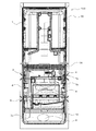
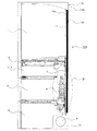
図1は、本発明の実施の形態に係る冷凍冷蔵庫の背面図である。図2は、この冷凍冷蔵庫の側断面図である。図3は、図2のQ部詳細図である。図4は、この冷凍冷蔵庫の冷凍サイクル回路を示す回路図である。なお、図1は、吸入管7の配置構成の理解を容易とするため、冷凍冷蔵庫100の外郭を構成する外箱15bの背面及び断熱材(真空断熱材12及び発泡断熱材13)を透過して示した図となっている。また、図4に示す矢印は、冷媒の流れ方向を示している。
以下、これら図1〜図4を用いて、本実施の形態に係る冷凍冷蔵庫100について説明する。
Embodiment.
FIG. 1 is a rear view of a refrigerator-freezer according to an embodiment of the present invention. FIG. 2 is a sectional side view of the refrigerator-freezer. FIG. 3 is a detailed view of a portion Q in FIG. FIG. 4 is a circuit diagram showing a refrigeration cycle circuit of the refrigerator-freezer. In FIG. 1, in order to facilitate the understanding of the arrangement configuration of the
Hereinafter, the refrigerator-
本実施の形態の冷凍冷蔵庫100は、図1に示すように、内箱15aと外箱15bとの間に真空断熱材12及びウレタン等の発泡断熱材13が充填された本体部15を備えている。なお、本実施の形態に係る本体部15は、外箱15bに真空断熱材12を取り付けて内箱15aと外箱15bとを組み立てた後、内箱15aと外箱15bとの間に発泡断熱材13を発泡充填する構成としている。このため、本実施の形態に係る本体部15は、図2,3に示すように、内箱15aと真空断熱材12との間に発泡断熱材13が設けられる構成となっている。
As shown in FIG. 1, the refrigerator-
この本体部15は、冷凍冷蔵庫100の外郭を構成するものであり、図1,2に示すように、内箱15aの内方が仕切り16で区画されて複数の貯蔵室が形成されている。詳しくは、本実施の形態に係る冷凍冷蔵庫100は、0℃〜5℃の冷蔵温度帯に冷却される冷蔵室1が本体部15の最上部に配置されたワークトップ型の冷凍冷蔵庫である。また、本実施の形態に係る冷凍冷蔵庫100は、冷蔵室1以外の貯蔵室として、製氷室2、切替室3、冷凍室4及び野菜室5を備えている。
As shown in FIGS. 1 and 2, the
製氷室2は、自動あるいは手動にて離氷動作を行い貯氷する貯蔵室であり、冷蔵室1の下方に配置されている。切替室3は、使用者の好みによって、例えば冷蔵温度帯(0℃〜5℃)からチルド温度帯(−2℃〜2℃)までの温度帯を段階的に設定できる貯蔵室である。この切替室3は、製氷室2と並んで冷蔵室1の下方に配置されている。冷凍室4は、貯蔵物を冷凍する冷凍温度帯(−15℃〜−20℃)に設定される貯蔵室であり、製氷室2及び切替室3の下方に配置されている。野菜室5は、野菜の貯蔵に好適な温度帯(0℃〜5℃)に設定される貯蔵室であり、冷凍室4の下方に配置されている。
The
また、冷凍冷蔵庫100は、図4に示すように、圧縮機9、凝縮器11、減圧手段14及び冷却器8が配管接続されて構成され、上記の各貯蔵室に供給する空気を冷却器8で冷却する冷凍サイクル回路6を備えている。
圧縮機9は、冷却器8から流出した低温低圧の冷媒を吸入管7(冷却器8と圧縮機9とを接続する配管)を介して吸入し、高温高圧のガス冷媒に圧縮するものである。この圧縮機9は、本体部15の後部下側に形成された機械室10に設けられている。凝縮器11は、圧縮機9で圧縮された高温高圧のガス冷媒を高圧の液冷媒に凝縮するものである。この凝縮器11は、例えばフィンチューブ型の熱交換器等を用いてもよいし、本体部15の側面部(詳しくは、内箱15aと外箱15bとの間に充填された発泡断熱材13内)に配置された配管を凝縮器11として用いてもよい。
In addition, as shown in FIG. 4, the refrigerator /
The
減圧手段14は、毛細管又は電磁膨張弁等であり、凝縮器から流出した高圧の液冷媒を低温低圧の気液二相冷媒に膨張させるものである。本実施の形態では、減圧手段14として毛細管を採用し、この毛細管と吸入管7とを所定の長さ区間(後述する吸入管7bの70%〜80%)だけハンダ付けして固定している。これにより、冷却器8によって毛細管を冷却することができるので、毛細管は熱回収がさらにしやすくなり、毛細管内の膨張工程の冷媒の乾き度を低下させることでエンタルピを大きくかせぐことができる。また、毛細管内の膨張工程の冷媒の乾き度を低下させることにより、毛細管内を流れる冷媒が液状態に近づくため、気泡発生(フォーミング)による毛細管内の流路抵抗が減少し、冷媒流量が増加する。このため、毛細管と吸入管7とをハンダ付けして固定することにより、冷凍能力を増大することができる。
The decompression means 14 is a capillary tube, an electromagnetic expansion valve, or the like, and expands the high-pressure liquid refrigerant flowing out of the condenser into a low-temperature and low-pressure gas-liquid two-phase refrigerant. In the present embodiment, a capillary tube is employed as the decompression means 14, and the capillary tube and the
冷却器8は、例えばフィンチューブ型の熱交換器であり、減圧手段14から流出した低温低圧の気液二相冷媒と各貯蔵室から流出した空気とを熱交換させ、当該空気を冷却するものである。本実施の形態では、冷凍室4の後方が図示せぬ仕切板で仕切られて、当該仕切板と内箱15aとの間に冷却室が形成されている。冷却器8は、この冷却室内に配置され、各貯蔵室から流出してこの冷却室内に流入してきた空気と冷媒とを熱交換させる。なお、冷却器8で冷却されたこの空気は、図示せぬ風路を通って、送風機等により各貯蔵室に供給される。
The
なお、冷却器8で熱交換して低圧となった冷媒は、冷却器8と圧縮機9とを接続する吸入管7を通って、再び圧縮機9に吸入される。
The refrigerant having a low pressure due to heat exchange in the
ここで、冷凍冷蔵庫100の消費電力量を改善する手段として、本体部15の断熱性能の向上が挙げられる。そして、本体部15の内容積(内箱15aの内方となる空間であり、貯蔵室が形成される空間の容積)は減少させず、かつ本体部15(つまり外箱15b)の外形サイズは拡大しないまま、断熱性能を向上させる為には、真空断熱材12の厚さを厚くする必要がある。このとき、真空断熱材12の厚さの限界は、内箱15aと外箱15bとの間の厚さから、発泡断熱材13が発泡工程において流れる厚さを差し引いた厚さ(つまり、発泡断熱材13の厚さ)になる。このため、本体部15の内容積は減少させず、かつ本体部15の外形サイズは拡大しないまま、内箱15aと外箱15bとの間に吸入管7を配置しようとした際、吸入管7の外径が発泡断熱材13の厚さよりも大きいと、真空断熱材12の厚さを薄くしなければならず、本体部15の断熱性能が悪化してしまう。
Here, improvement of the heat insulation performance of the main-
また、本実施の形態に係る本体部15は、本体部15の外形サイズは拡大しないまま、本体部15の内容積(内箱15aの内方となる空間であり、貯蔵室が形成される空間の容積)の増加を図っている。このため、本実施の形態に係る本体部15は、従来にはない新たな技術思想に基づいて製作されている。詳しくは、従来の冷凍冷蔵庫の本体部は、発泡断熱材が主に断熱機能を担い、真空断熱材は発泡断熱材の断熱機能を補助するという技術思想によって製作されていた。一方、本実施の形態に係る本体部15は、真空断熱材12が主に断熱機能を担うという新たな技術思想に基づいて製作されている。このため、本実施の形態に係る本体部15は、内箱15aと外箱15bとの間の空間における真空断熱材12の充填率を40%〜80%としており、さらに、外箱15bの表面積に対する真空断熱材12の面積比率(外箱15bの表面を覆う真空断熱材12の面積比率)を60%以上としている。また、発泡断熱材13は、真空断熱材12の固定、及び、本体部15の強度確保を主目的として、その曲げ弾性率を15.0MPa以上としている。つまり、本体部15の外形サイズは拡大しないまま、本体部15の内容積の増加を図った本実施の形態に係る本体部15は、発泡断熱材13の厚さがさらに薄くなり、真空断熱材12の厚さを確保しつつ内箱15aと外箱15bとの間に吸入管7を配置することがさらに困難になっている。
In addition, the
しかしながら、内箱15aの内方に吸入管7を配置すると、貯蔵室を形成することができる空間に吸入管7を配置することとなるため、本体部15の内容積、つまり貯蔵室の容積が減少してしまうという。また、後述の図5を参照すると分かるように、吸入管7の温度は冷却器8の出口より1200mmを超えると、10℃近くになることがある。このため、内箱15aの内方に吸入管7を配置すると、貯蔵室と吸入管7との温度差によって吸入管7に結露が生じてしまうという。また、吸入管7の結露対策として吸入管7を断熱材で覆った場合、吸入管7を覆う断熱材の分だけコストが上昇してしまい、冷凍冷蔵庫100のコストが増加してしまう。
However, when the
そこで、本実施の形態1に係る冷凍冷蔵庫100では、以下のような構成により、本体部15の内容積は減少させず(又は、本体部15の内容積を増加させつつ)、かつ本体部15の外形サイズは拡大しないまま、内箱15aと外箱15bとの間に吸入管7を配置している。
Therefore, in the refrigerator-
本体部15の壁厚(内箱15aと外箱15bとの間の厚さ、つまり断熱厚さ)は、対向する貯蔵室の温度帯に応じて異なる。つまり、製氷室2、切替室3及び冷凍室4の温度帯は冷蔵室1の温度帯よりも低いため、製氷室2、切替室3及び冷凍室4と対向する範囲の本体部15の壁厚は、冷蔵室1と対向する範囲の本体部15の壁厚よりも厚くなっている。すなわち、図2,3に示すように、製氷室2、切替室3及び冷凍室4と対向する範囲の本体部15に設けられる真空断熱材12の厚さを、冷蔵室1と対向する範囲の本体部15に設けられる真空断熱材12の厚さと同等まで厚くしても、製氷室2、切替室3及び冷凍室4と対向する範囲の本体部15には、吸入管7を配置する領域(発泡断熱材13の厚み)を確保することができる。したがって、本実施の形態に係る冷凍冷蔵庫100においては、吸入管7を、内箱15aと外箱15bとの間であって、冷蔵室1よりも低い温度帯に設定可能な貯蔵室(製氷室2、切替室3及び冷凍室4)と対向する範囲に配置している。
The wall thickness of the main body 15 (the thickness between the
以下、吸入管7の構成について、さらに詳細に説明する。
Hereinafter, the configuration of the
本実施の形態に係る吸入管7は、図2に示すように、冷却器8から圧縮機9に向かって、外径6.35mmで肉厚0.5mmの吸入管7a、外径7.7mmで肉厚0.5mmの吸入管7b、及び、外径6.35mmで肉厚0.5mmの吸入管7cが順次接続されて構成されている。吸入管7aは、冷却器8の出口に接続される配管であり、本実施の形態では230mmの長さとなっている。吸入管7bは、一方の端部が吸入管7aと接続され、他方の端部が吸入管7cと接続される配管である。この吸入管7bは、その大部分が発泡断熱材13の内部に設置される配管であり、本実施の形態では2500mmの長さとなっている。なお、吸入管7bにおける吸入管7c側の端部は、90mmほど機械室10に突出している。吸入管7cは、吸入管7bと圧縮機9とを接続する配管であり、本実施の形態では270mmの長さとなっている。
As shown in FIG. 2, the
このように構成された吸入管7の大部分(より詳しくは、内箱15aと外箱15bとの間に配置された部分)は、図1に示すように冷蔵室1よりも低い温度帯に設定可能な貯蔵室(製氷室2、切替室3及び冷凍室4)と対向する範囲において、図2,3に示すように内箱15aと真空断熱材12との間の発泡断熱材13内に設けられる。
Most of the
図1を用いて、吸入管7の配置構成をさらに詳しく説明する。なお、以下では、図4で示した冷凍サイクル回路6内の冷媒流れ方向にしたがって、吸入管7の配置構成を説明していく。
The arrangement configuration of the
まず、吸入管7は、冷却器8の出口から、内箱15aと真空断熱材12との間に設けられた発泡断熱材13の内部に入り、そこから上方向に向かって配置されている。そして、吸入管7は、製氷室2と冷蔵室1とを区画する仕切り16の下方、つまり、製氷室2と対向する範囲で180°反転して下方向に向かうように配置されている。
First, the
次に、下方向に向かうように配置された吸入管7は、冷却器8の背面側(つまり、冷却器8の投影背面)の中程で水平方向に向かうように配置されている。そして、水平方向に向かうように配置された吸入管7は、冷却器8の背面側で上方向に向かうように配置されている。
Next, the
この吸入管7は、冷凍室4と切替室3とを区画する仕切り16近傍で水平方向に向かうように配置された後、切替室3と製氷室2とを区画する仕切り16近傍で180°反転するように配置されている。この吸入管7は、切替室3と冷蔵室1とを区画する仕切り16の下方、つまり、切替室3と対向する範囲で水平方向に配置された後、下方向に向かうように配置されている。
The
この下方向に向かうように配置された吸入管7は、冷却器8の投影背面を通過させないように配置された後、野菜室5と対向する範囲に配置され、その後、内箱15aと真空断熱材12との間に設けられた発泡断熱材13から機械室10に出て、圧縮機9の吸入側に接続される。なお、野菜室5の温度帯は冷蔵室1と同じ温度帯であるが、本実施の形態に係る本体部15は、野菜室5と対向する範囲の壁厚を、冷蔵室1よりも低い温度帯に設定可能な貯蔵室(製氷室2、切替室3及び冷凍室4)と対向する範囲の壁厚と同じ厚さとしている。これは、機械室10から野菜室5に熱が侵入することを抑制するためである。
The
ここで、上述のように、本実施の形態では、切替室3の背面側から下方向に向かうように配置された吸入管7は、冷却器8の投影背面を通過させないように配置されている。一方、従来の冷凍冷蔵庫(例えば特許文献1参照)では、当該部分の吸入管は冷却器8の投影背面を通過させるように配置している。本実施の形態に係る冷凍冷蔵庫100が当該部分の吸入管7を冷却器8の投影背面を通過させないように配置している理由は、以下のためである。
Here, as described above, in the present embodiment, the
図5は、本発明の実施の形態に係る冷凍冷蔵庫の、吸入管長さと吸入管温度との関係を示す特性図である。この図5は、横軸に冷却器8側からの吸入管7の長さを示しており、縦軸に吸入管7の温度を示している。なお、図5に示すデータを測定した時の冷凍冷蔵庫100周辺の外気温度は30℃であり、冷却器8の平均温度は約−25℃であった。
FIG. 5 is a characteristic diagram showing the relationship between the suction pipe length and the suction pipe temperature in the refrigerator-freezer according to the embodiment of the present invention. In FIG. 5, the horizontal axis indicates the length of the
図5に示すように、冷却器8から圧縮機9に向かうにつれて、吸入管7(換言すると、該吸入管7を流れる冷媒)は、周囲から加熱されて徐々にその温度が上昇していく。そして、冷却器8から1000mmを超えると、吸入管7の温度は0℃以上になる。さらに、機械室10の入口付近(発泡断熱材13から機械室10に突出する直前の吸入管7部分)までいくと、吸入管7の温度は、20℃近くにまで上昇する。
As shown in FIG. 5, the suction pipe 7 (in other words, the refrigerant flowing through the suction pipe 7) is heated from the surroundings and gradually increases in temperature as it goes from the
このため、機械室10の入口付近の吸入管7を冷却器8の投影背面に配置すると、吸入管7と冷却器8との間の温度差は50℃近くにもなってしまう。したがって、機械室10の入口付近の吸入管7を冷却器8の投影背面に配置すると、冷却器8が吸入管7の温度を吸収して、冷却器8の温度が上昇してしまうので、冷却性能が悪化してしまう。ここで、各貯蔵室から冷却器8(冷却室)に流入する空気に着目すると、最も温度が高く流量が多い空気は、冷蔵室1(温度帯0℃〜5℃)から冷却器8に流入する空気であり、約3℃である。このため、冷蔵室1から冷却器8に流入する空気よりも低い温度になっている吸入管7部分であれば、冷却器8の冷却性能を悪化させない。このため、本実施の形態では、吸入管7の冷却器8から圧縮機9までの長さにおける冷却器から1000mmを超えた部分を、冷却器8の投影背面に配置しないようにするため、切替室3の背面側から下方向に向かうように配置された吸入管7を、冷却器8の投影背面を通過させないように配置している。
For this reason, if the
以上、本実施の形態のように構成された冷凍冷蔵庫100(冷蔵室1が最上段に配置されたワークトップ型の冷凍冷蔵庫)においては、吸入管7を、内箱15aと外箱15bとの間であって、冷蔵室1よりも低い位置に形成された貯蔵室と対向する範囲に配置している。つまり、本実施の形態に係る冷凍冷蔵庫100は、冷蔵室1と対向する位置における内箱15aと外箱15bとの間の空間を他の貯蔵室よりも薄くすることができる。このため、本実施の形態に係る冷凍冷蔵庫100は、本体部15の外形サイズは拡大しないままで本体部15の内容積を増大しつつ、消費電力量の改善と省スペース化の双方の要求を満たすことができる。
As described above, in the refrigerator-
また、本実施の形態に係る冷凍冷蔵庫100は、吸入管7の冷却器8から圧縮機9までの長さにおける冷却器8から1000mmを超えた部分を、冷却器8の投影背面に配置していない。このため、本実施の形態に係る冷凍冷蔵庫100は、冷却器8が吸入管7の温度を吸収すること、つまり、冷却器8の温度が上昇してしまうことを防止できるので、冷却性能が悪化してしまうことも防止できる。
Further, in the refrigerator-
また、本実施の形態に係る冷凍冷蔵庫100は、吸入管7を内箱15aと外箱15bとの間、つまり従来より断熱材が設けられている範囲に配置している。このため、本実施の形態に係る冷凍冷蔵庫100は、吸入管7を覆う断熱材を新たに設ける必要がないので、冷凍冷蔵庫100のコストが増加することも防止できる。
Moreover, the refrigerator-
なお、本実施の形態では、吸入管7を本体部15の背面側のみに配置しているが、吸入管7を本体部15の側面側に配置することが可能である。しかしながら、冷却器8と圧縮機9とを接続する吸入管7は、冷凍サイクル回路6の構成間を接続する他の配管よりも太い。このため、吸入管7を本体部15の背面側のみに配置した場合、吸入管7を本体部15の側面側に配置した場合と比べ、本体部15の側面部の厚みを薄くすることができる。つまり、吸入管7を本体部15の背面側のみに配置した場合、吸入管7を本体部15の側面側に配置した場合と比べ、本体部15の内容積を増大することができる。したがって、本実施の形態では、吸入管7を本体部15の背面側のみに配置している。
In the present embodiment, the
また、本実施の形態では、内箱15aと真空断熱材12との間に吸入管7を配置しているが、吸入管7を真空断熱材12と外箱15bとの間に配置してもよい。より詳しくは、真空断熱材12を内箱15aに取り付けて、真空断熱材12と外箱15bとの間に発泡断熱材13を充填し、該発泡断熱材13の内部(つまり、真空断熱材12と外箱15bとの間)に吸入管7を配置してもよい。しかしながら、内箱15aの表面形状は外箱15bの表面形状よりも凹凸が多いため、内箱15aに真空断熱材12を取り付けるよりも、外箱15bに真空断熱材12を取り付ける方が、本体部15の製造が容易となる。このため、本実施の形態では、内箱15aと真空断熱材12との間に吸入管7を配置している。
In this embodiment, the
1 冷蔵室、2 製氷室、3 切替室、4 冷凍室、5 野菜室、6 冷凍サイクル回路、7(7a〜7c) 吸入管、8 冷却器、9 圧縮機、10 機械室、11 凝縮器、12 真空断熱材、13 発泡断熱材、14 減圧手段、15 本体部、15a 内箱、15b 外箱、16 仕切り、100 冷凍冷蔵庫。
DESCRIPTION OF
Claims (3)
圧縮機、凝縮器、減圧手段及び冷却器が配管接続され、前記冷却器で前記貯蔵室に供給する空気を冷却する冷凍サイクル回路と、
を備え、
前記冷蔵室が最上段に配置されたワークトップ型の冷凍冷蔵庫であって、
前記冷却器と前記圧縮機との間を接続する吸入管を、前記内箱と前記外箱との間であって、前記冷蔵室よりも低い位置に形成された前記貯蔵室と対向する範囲に配置すると共に、
前記吸入管の前記冷却器から前記圧縮機までの長さにおける前記冷却器から1000mmを超えた部分を、前記冷却器の投影背面に配置していないことを特徴とする冷凍冷蔵庫。 A main body in which a vacuum heat insulating material and a foam heat insulating material are filled between the inner box and the outer box, and a plurality of storage chambers including at least a refrigerator compartment are formed inside the inner box,
A compressor, a condenser, a decompression unit, and a cooler connected by piping, and a refrigerating cycle circuit that cools air supplied to the storage chamber by the cooler;
With
A work top type refrigerator-freezer in which the refrigerator compartment is arranged at the top,
A suction pipe connecting between the cooler and the compressor is provided between the inner box and the outer box, and in a range facing the storage chamber formed at a position lower than the refrigerator compartment. As well as
A refrigerator-freezer, wherein a portion of the suction pipe that exceeds 1000 mm from the cooler in a length from the cooler to the compressor is not disposed on a projected rear surface of the cooler.
Priority Applications (2)
| Application Number | Priority Date | Filing Date | Title |
|---|---|---|---|
| JP2013151791A JP2015021690A (en) | 2013-07-22 | 2013-07-22 | Freezer refrigerator |
| CN201420358110.0U CN204006910U (en) | 2013-07-22 | 2014-06-30 | Refrigerator |
Applications Claiming Priority (1)
| Application Number | Priority Date | Filing Date | Title |
|---|---|---|---|
| JP2013151791A JP2015021690A (en) | 2013-07-22 | 2013-07-22 | Freezer refrigerator |
Publications (2)
| Publication Number | Publication Date |
|---|---|
| JP2015021690A true JP2015021690A (en) | 2015-02-02 |
| JP2015021690A5 JP2015021690A5 (en) | 2015-10-01 |
Family
ID=52046899
Family Applications (1)
| Application Number | Title | Priority Date | Filing Date |
|---|---|---|---|
| JP2013151791A Pending JP2015021690A (en) | 2013-07-22 | 2013-07-22 | Freezer refrigerator |
Country Status (2)
| Country | Link |
|---|---|
| JP (1) | JP2015021690A (en) |
| CN (1) | CN204006910U (en) |
Citations (3)
| Publication number | Priority date | Publication date | Assignee | Title |
|---|---|---|---|---|
| JPH11132631A (en) * | 1997-10-28 | 1999-05-21 | Matsushita Refrig Co Ltd | Refrigerator |
| JP2003214754A (en) * | 2002-01-24 | 2003-07-30 | Sanyo Electric Co Ltd | Refrigerator |
| JP2005048979A (en) * | 2003-07-30 | 2005-02-24 | Hitachi Home & Life Solutions Inc | Refrigerator |
-
2013
- 2013-07-22 JP JP2013151791A patent/JP2015021690A/en active Pending
-
2014
- 2014-06-30 CN CN201420358110.0U patent/CN204006910U/en not_active Expired - Lifetime
Patent Citations (3)
| Publication number | Priority date | Publication date | Assignee | Title |
|---|---|---|---|---|
| JPH11132631A (en) * | 1997-10-28 | 1999-05-21 | Matsushita Refrig Co Ltd | Refrigerator |
| JP2003214754A (en) * | 2002-01-24 | 2003-07-30 | Sanyo Electric Co Ltd | Refrigerator |
| JP2005048979A (en) * | 2003-07-30 | 2005-02-24 | Hitachi Home & Life Solutions Inc | Refrigerator |
Also Published As
| Publication number | Publication date |
|---|---|
| CN204006910U (en) | 2014-12-10 |
Similar Documents
| Publication | Publication Date | Title |
|---|---|---|
| JP6192634B2 (en) | Insulated box, refrigerator and hot water storage device provided with the insulated box | |
| JP4696906B2 (en) | refrigerator | |
| US20060150663A1 (en) | Refrigerator | |
| JP5932732B2 (en) | refrigerator | |
| KR20110071167A (en) | Refrigerator | |
| JP2014048030A (en) | Cooling warehouse | |
| CN104380015B (en) | Refrigerator | |
| JP2015052401A (en) | Refrigerator | |
| WO2015025477A1 (en) | Refrigerator | |
| TWI555956B (en) | Refrigerator | |
| JP6714382B2 (en) | refrigerator | |
| JP2015052400A (en) | Refrigerator and method of manufacturing the same | |
| JP2018004248A (en) | Refrigerator | |
| JP2015021690A (en) | Freezer refrigerator | |
| JP5985942B2 (en) | Refrigerator | |
| JP2017156027A (en) | refrigerator | |
| JP5401866B2 (en) | refrigerator | |
| JP2011080692A (en) | Refrigerator | |
| JP4552623B2 (en) | refrigerator | |
| JP6603017B2 (en) | refrigerator | |
| EP2397797A1 (en) | Refrigerator | |
| WO2024002179A1 (en) | Refrigerator | |
| JP2007064590A (en) | Refrigerator | |
| JP2022123224A (en) | refrigerator | |
| JP6379348B2 (en) | refrigerator |
Legal Events
| Date | Code | Title | Description |
|---|---|---|---|
| A521 | Written amendment |
Free format text: JAPANESE INTERMEDIATE CODE: A523 Effective date: 20150813 |
|
| A621 | Written request for application examination |
Free format text: JAPANESE INTERMEDIATE CODE: A621 Effective date: 20150813 |
|
| A131 | Notification of reasons for refusal |
Free format text: JAPANESE INTERMEDIATE CODE: A131 Effective date: 20160426 |
|
| A977 | Report on retrieval |
Free format text: JAPANESE INTERMEDIATE CODE: A971007 Effective date: 20160428 |
|
| A521 | Written amendment |
Free format text: JAPANESE INTERMEDIATE CODE: A523 Effective date: 20160620 |
|
| A02 | Decision of refusal |
Free format text: JAPANESE INTERMEDIATE CODE: A02 Effective date: 20161108 |