JP2015015936A - Levee plastering machine - Google Patents
Levee plastering machine Download PDFInfo
- Publication number
- JP2015015936A JP2015015936A JP2013146756A JP2013146756A JP2015015936A JP 2015015936 A JP2015015936 A JP 2015015936A JP 2013146756 A JP2013146756 A JP 2013146756A JP 2013146756 A JP2013146756 A JP 2013146756A JP 2015015936 A JP2015015936 A JP 2015015936A
- Authority
- JP
- Japan
- Prior art keywords
- pair
- side cover
- link
- link members
- soil
- Prior art date
- Legal status (The legal status is an assumption and is not a legal conclusion. Google has not performed a legal analysis and makes no representation as to the accuracy of the status listed.)
- Granted
Links
Images


Landscapes
- Soil Working Implements (AREA)
Abstract
Description
本発明は、畦塗り機に関する。 The present invention relates to a wrinkle coater.
従来において、畦塗り機における土飛散防止のためのサイドカバーの下げ位置を規制する機構として、例えば「前処理体のサイドカバー26は、・・・カバー27との間において、上下一対の平行リンク41により上下動自在に支持されている。サイドカバー26には、ストッパ支持部材43を介してストッパ支持杆42がピンの差し込みにより有段に・・・、または蝶ねじ42bにより無断階・・・に上下移動可能に支持され、ストッパ支持部材43の上端部には、・・・平行リンク41が上動したとき当接し、サイドカバー26下げ位置を規制するストッパ42aを設けて」成る規制機構があった(特許文献1の請求項1、[0002]〜[0008]、[0018]〜[0021]、図1〜図10参照。)。
Conventionally, as a mechanism for restricting the lowering position of the side cover for preventing the scattering of soil in the coater, for example, “a
従来の畦塗り機におけるサイドカバーの下げ位置の規制機構は部品点数が多く、複雑であった。
畦塗り機のサイドカバーにおける、特に下端位置を従来と同等に規制しつつ、より簡素な構造の規制部材が要求されていた。
The regulation mechanism for the position of lowering the side cover in the conventional coater has a large number of parts and is complicated.
There has been a demand for a regulating member having a simpler structure while regulating the lower end position of the side cover of the glazing machine as much as in the past.
よって、本発明が解決しようとする課題は、簡素な構造の規制部材によりサイドカバーの下端位置を規制可能な畦塗り機を提供することである。 Therefore, the problem to be solved by the present invention is to provide a wrinkling machine capable of regulating the lower end position of the side cover by a regulating member having a simple structure.
前記課題を解決するための手段として、本発明に係る畦塗り機は、走行機体の後部に装着され、走行機体から動力を受け、元畦及び圃場を耕耘して畦状に土を盛り上げる前処理体と、前処理体より後方に設けられ、前処理体により耕耘された土を畦として成形する整畦体と、前処理体の左右方向外側に設けられ、耕耘時に土の飛散を防止するサイドカバーと、を備える畦塗り機であって、前処理体に対してサイドカバーを上下方向に回動可能に連結する一対のリンク部材を有し、一対のリンク部材は、間隙を設けて平行に配置され、一対のリンク部材の一方に、間隙に向かって凸部が形成されている。 As means for solving the above-mentioned problems, the paddy coater according to the present invention is attached to the rear part of the traveling machine body, receives power from the traveling machine body, cultivates the main fence and the field, and pre-heats the soil in a bowl shape A body, a trimming body which is provided behind the pretreatment body and forms the soil cultivated by the pretreatment body as a ridge, and a side which is provided on the outer side in the left and right direction of the pretreatment body and prevents scattering of soil during tillage A pair of link members that connect the side cover to the pretreatment body so as to be rotatable in the vertical direction, and the pair of link members are provided in parallel with a gap therebetween. Arranged and a convex portion is formed on one of the pair of link members toward the gap.
本発明に係る畦塗り機において、一対のリンク部材の他方に、前記一対のリンク部材がそれぞれの回動軌道中の上端に達したときに前記凸部が嵌り込む凹部が形成されていることが好ましい。 In the plastering machine according to the present invention, the other of the pair of link members is formed with a recess into which the projection fits when the pair of link members reach the upper end in each of the rotating tracks. preferable.
本発明に係る畦塗り機において、一方のリンク部材と他方のリンク部材とが同一形状となるように一対のリンク部材のそれぞれに凸部及び凹部が形成され、一方のリンク部材に形成された凸部が間隙に向かって形成される凸部であり、他方のリンク部材に形成された凹部が凸部に嵌り込み得る凹部であることが好ましい。 In the plastering machine according to the present invention, a convex portion and a concave portion are formed on each of the pair of link members so that one link member and the other link member have the same shape, and the convex formed on the one link member. The part is preferably a convex part formed toward the gap, and the concave part formed in the other link member is preferably a concave part that can be fitted into the convex part.
更に、本発明に係る畦塗り機において、一対のリンク部材の回動軌道中の下端位置が、前処理体が盛り上げた土にサイドカバーが当接又は近接する位置であることが好ましい。 Furthermore, in the plastering machine according to the present invention, it is preferable that the lower end position of the pair of link members in the rotating track is a position where the side cover is in contact with or close to the soil raised by the pretreatment body.
本発明によると、一対のリンク部材のうち、一方に凸部を設けた簡素な構造を採用することによって、前処理体とサイドカバーとを連結するだけでなく、サイドカバーの上下方向への回動軌道中において、複雑なサイドカバーの下げ位置の規制機構を設けなくともサイドカバーの下げ位置を規制することができる畦塗り機を提供することができる。 According to the present invention, by adopting a simple structure in which a convex portion is provided on one of the pair of link members, not only the pretreatment body and the side cover are connected, but also the side cover is rotated in the vertical direction. It is possible to provide a wrinkle coater that can regulate the lowered position of the side cover without providing a complicated mechanism for regulating the lowered position of the side cover in the moving track.
本発明に係る畦塗り機の一実施形態について、図面を参照しつつ説明する。なお、以下の説明においては、図1の左下に示すように、図1の紙面に平行な方向を水平方向とし、図1の紙面に直交する方向を上下方向とする。図1に示す走行機体100の前後進方向でかつ水平方向を前後方向とし、前後方向に直交しかつ水平方向を左右方向とする。また、図1の左右方向が走行機体の幅方向に相当する。 DESCRIPTION OF THE PREFERRED EMBODIMENTS An embodiment of a plastering machine according to the present invention will be described with reference to the drawings. In the following description, as shown in the lower left of FIG. 1, the direction parallel to the paper surface of FIG. 1 is the horizontal direction, and the direction orthogonal to the paper surface of FIG. 1, the horizontal direction is the front-rear direction, and the horizontal direction is the left-right direction. Moreover, the left-right direction of FIG. 1 is equivalent to the width direction of a traveling body.
先ず、図1〜4を参照しつつ、本発明に係るオフセット作業機の一実施形態の概要を説明する。 First, an outline of an embodiment of an offset working machine according to the present invention will be described with reference to FIGS.
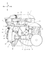
図1に示すように、畦塗り機1は、装着部2、連結部3、作業部4、動力伝達部5、第1伸縮シリンダ61、及び第2伸縮シリンダ62を備えている。畦塗り機1は、本発明に係る畦塗り機の一例であり、走行機体の走行とともに進行して圃場の隅部まで畦塗り作業を連続的に行うことができる。
As shown in FIG. 1, the
装着部2は、トラクタ等の走行機体100の後部に、畦塗り機1を装着する部材である。
装着部2は、駆動用シャフト7、及び3点リンクヒッチ機構(図1〜図4には図示せず)等の適宜の連結部材を有する。
装着部2における3点リンクヒッチ機構としては、例えば1つのトップリンク連結部及び2つのロアーリンク連結部を有する連結機構を挙げることができ、走行機体100に対して着脱自在に取付けられる。なお、装着部2が作業中に走行機体100から脱離しないように、装着部2と走行機体100との連結は強固に固定される。
また、装着部2における駆動用シャフト7は、走行機体100のPTO軸(図1〜図4には図示せず)に対して、図示しない適宜のユニバーサルジョイント等を介して連結される、前方に突出した軸体である。駆動用シャフト7は、畦塗り機1においてPTO軸から最初に動力を受ける部材である。
走行機体100に対して装着部2を一旦取り付けると、走行機体100から装着部2を脱離させるまで、畦塗り作業中であっても走行機体100に対する装着部2の取付位置及び方向は一定又は略一定である。
The
The
Examples of the three-point link hitch mechanism in the
Further, the
Once the
連結部3は、装着部2から延在し、装着部2と後述の作業部4とを連結する部材である。
連結部3は、オフセットフレーム8、リンクロッド9及び支持フレーム10を有する。
オフセットフレーム8は、板状部材又は断面矩形の筒状部材等が組み付けられて成る長尺のフレーム状部材である。オフセットフレーム8は、装着部2から後方向に延在し、装着部2に対して水平面上で回動可能なように取付けられる。図1〜図4に示すオフセットフレーム8は、カバーに覆われた状態で示しており、該カバー内には後述の動力伝達部5を収容している。
リンクロッド9は、棒状部材又は筒状部材等が適宜に用いられて成る、オフセットフレーム8と略同尺のフレーム状部材である。リンクロッド9は、装着部2から後方向に延在し、装着部2に対して水平面上で回動可能なように取付けられる。
支持フレーム10は、棒状部材又は断面矩形の筒状部材等が適宜に用いられて成るフレーム状部材である。支持フレーム10は、装着部2に対して平行となるように配置される。オフセットフレーム8及びリンクロッド9のそれぞれの一端部は上述したように装着部2に回動可能に取付けられている。これに対して、オフセットフレーム8及びリンクロッド9のそれぞれの他端部は、共に支持フレーム10に対して水平面上で回動可能なように、支持フレーム10に取付けられている。すなわち、オフセットフレーム8及びリンクロッド9は、支持フレーム10によって平行状態を維持しつつ回動することになる。
なお、図1〜図4に示す畦塗り機1は、連結部3がオフセット位置に配置された状態、つまりオフセットフレーム8及びリンクロッド9の軸線が前後方向に対して傾斜するように連結部3を変位させた状態である。
The connecting portion 3 is a member that extends from the
The connecting portion 3 includes an
The
The
The
1 to 4 is a state in which the connecting portion 3 is disposed at the offset position, that is, the connecting portion 3 so that the axes of the
作業部4は、前処理体11、整畦体12、サイドカバー13及びリンク部材14を有する。
前処理体11は、装着部2及び連結部3を介して、走行機体100の後部に接続され、かつ走行機体100から動力を受ける部材であり、元畦及び圃場を耕耘して畦状に土を盛り上げる。
整畦体12は、前処理体11より後方に設けられ、前処理体12により耕耘された土を畦として成形する部材である。
特に図2に示すように、前処理体11及び整畦体12は、作業部支持体15に取付けられている。作業部支持体15は、複数の筒状部材が組合せられて成る。作業部支持体15は、オフセットフレーム8の後端部から下側に突出する縦筒部16と、縦筒部16の下端部から水平方向に延在する横筒部17とを有する。
サイドカバー13は、前処理体11の左右方向外側に設けられ、前処理体11の耕耘時に土の飛散を防止する部材である。
また図4に示すように、リンク部材14は、略短冊形状を成す一対の部材であり、前処理体11に対してサイドカバー13を上下方向に回動可能に連結し、相互に間隙を設けて平行となるように配設される。
作業部4についての詳細な説明は、動力伝達部5と共に後述する。また、サイドカバー13及びリンク部材14についての詳細な説明は、図5〜図7を参照しつつ行うことにする。
The working
The
The trimming
In particular, as shown in FIG. 2, the
The side cover 13 is a member that is provided on the outer side in the left-right direction of the
As shown in FIG. 4, the
Detailed description of the working
図1に示すように、動力伝達部5は、入力軸18と、環状チェーン19と、中継軸20と、第1出力軸21と、第2出力軸22とを有する。動力伝達部5は、駆動用シャフト7が受ける動力を、作業部4における前処理体11及び整畦体12に伝達する部材である。
入力軸18は、その軸線が上下方向に対して平行となるように、装着部2に取付けられる軸体である。入力軸18は、その軸線を中心にして回転可能となっている。入力軸18及び駆動用シャフト7には、それぞれ図示しないギヤが固定的に付設されており、該ギヤ同士が歯合している。よって、走行機体100から駆動用シャフト7に対して伝達される動力は、ギヤにより入力軸18に伝達可能となっている。
中継軸20は、その軸線が上下方向に対して平行となるように、オフセットフレーム8に取付けられる軸体である。中継軸20は、その軸線を中心にして回転可能となっている。また、中継軸20は、オフセットフレーム8に取付けられる上端部から下側に延在しており、図2に示す作業部支持体15の縦筒部16内を挿通している。
環状チェーン19は、入力軸18と中継軸20との間に掛け渡される無端状部材であり、入力軸18及び中継軸20の各上端部に設けられた図示しないスプロケットと歯合している。したがって、走行機体100から入力軸18に伝達された動力は、環状チェーン19を介して中継軸20に伝達可能となっている。
第1出力軸21は、中継軸20の下端部に接続される軸体であり、中継軸20に対して直交し、水平方向でかつ略前後方向に延在する。第1出力軸21は、その軸線を中心にして回転可能となっている。第1出力軸21の後端部及び中継軸20の下端部には、それぞれ図示しないギヤが固定的に付設されており、該ギヤ同士が歯合している。よって、走行機体100から中継軸20に対して伝達される動力は、ギヤにより第1出力軸21に伝達可能となっている。第1出力軸21は、図2に示す作業部支持体15の横筒部17内を挿通している。つまり、縦筒部16と横筒部17との接合部近傍の内部において、中継軸20と第1出力軸21とが歯合するようになっている。
第2出力軸22は、第1出力軸21に側方から接続される軸体であり、第1出力軸21に対して斜交し、水平方向でかつ略左右方向に延在する。第2出力軸22は、その軸線を中心にして回転可能となっている。第2出力軸22の端部及び第1出力軸21の周側面には、それぞれ図示しないギヤが固定的に付設されており、該ギヤ同士が歯合している。よって、走行機体100から第1出力軸21に対して伝達される動力は、ギヤにより第2出力軸22に伝達可能となっている。
第1出力軸21は、一端部が中継軸20に接続され、他端部が前処理体11に接続される。また、第2出力軸22は、一端部が第1出力軸21に接続され、他端部が適宜の動力伝達手段を介して整畦体12に接続される。
As shown in FIG. 1, the
The
The
The
The
The
The
以下に、作業部4、及び作業部4と動力伝達部5との関係について詳述する。
Hereinafter, the working
本実施形態においては、前処理体11は、天場処理部23と前処理部24とを有している。
天場処理部23は、旧畦の天場を耕耘する部材であり、特に図3及び図4に示すように、回転軸25及び天場用耕耘爪26を有する。天場用耕耘爪26は、回転可能な軸体である回転軸25の周側面に放射状にかつ固定的に複数個装着されている。天場処理部23は、第1出力軸21の軸線を中心にして回動可能となっている。また、耕耘する旧畦の高さ及び成形しようとする畦の高さに応じて天場処理部23の上下位置を調節可能な部材として、上下位置調節部27が天場処理部23の後側に付設されている。
前処理部24は、圃場及び旧畦の法面を耕耘する部材であり、耕耘爪28を有する。第1出力軸21は、中継軸20から前処理体11における前処理部24まで延在している。また、第1出力軸21が挿通する横筒部17は耕耘爪28の周囲に設けられるカバー体に固定的に接続されている。耕耘爪28は、第1出力軸21の前端部に設けられた回転可能な耕耘用回転軸50の周側面に放射状にかつ固定的に複数個装着されている。前処理部24は、天場処理部23の後方に設けられている。
天場処理部23の回転軸25と、第1出力軸21とは、天場用動力伝達部29を介して連結されている。天場用動力伝達部29は、例えば動力伝達部5における環状チェーン17とは別の第2環状チェーン(図示せず)等の適宜の動力伝達部材を有する。例えば第2環状チェーンは、耕耘用回転軸50と回転軸25との間に掛け渡され、第1出力軸21及び回転軸25にそれぞれ歯合している。したがって、走行機体100から第1出力軸21に伝達された動力は、第2環状チェーンを介して回転軸25に伝達可能となっている。
In the present embodiment, the
The
The
The rotating
整畦体12は、円錐ドラム30と円筒部31とを有している。
円錐ドラム30は、外側に向かって、つまり図1に示す畦塗り機1においては右側に向かって先窄まりとなるように配置される略円錐台形状の部材である。円筒部31は、円錐ドラム30の外側中央部に突設される有底円筒体である。円筒部31は、その軸線が第2出力軸22の軸線に対して平行となるように配置される。円錐ドラム30と円筒部31とは、相互に固定されている。
整畦体12は、円筒部31の軸線を中心にして回転可能となっている。円錐ドラム30の内部には、円筒部31の軸線を中心にして回転する適宜の軸体(図1〜図4には図示せず)が内部に設けられている。整畦体12に接続される第2出力軸22と、円筒部31の軸体とは、図2に示すように、整畦用動力伝達部32を介して連結されている。整畦用動力伝達部32は、上記環状チェーン17及び第2環状チェーンとは別の第3環状チェーン(図示せず)等の適宜の動力伝達部材を有する。例えば第3環状チェーンは、第2出力軸22と円錐ドラム30内の軸体との間に掛け渡され、第2出力軸22及び該軸体にそれぞれ歯合している。したがって、走行機体100から第2出力軸22に伝達された動力は、第3環状チェーンを介して円錐ドラム30の軸体に伝達可能となっている。
The trimming
The
The trimming
以上により、走行機体100のPTO軸から畦塗り機1に動力が伝達されると、動力伝達部5における第1出力軸21により天場処理部23及び前処理部24がそれぞれ回転し、第2出力軸22により整畦体12が回転することとなる。
As described above, when power is transmitted from the PTO shaft of the traveling
特に図1及び図2に示すように、連結部3の支持フレーム10に対してオフセットフレーム8及び作業部支持体15の縦筒部16が回動可能に取付けられ、かつ、横筒部17に前処理体11及び整畦体12が取付けられている。すなわち、畦塗り機1は、支持フレーム10から作業部4が垂下するように組み付けられている。
縦筒部16は、その軸線を中心にして回動可能に、支持フレーム10に対して取付けられている。横筒部17は、縦筒部16に対して固定的に接合されている。縦筒部16がその軸線を中心にして回動すると、縦筒部16に取付けられて成る横筒部17が水平面上で回動することとなる。横筒部17が水平面上で回動すると、作業部4が水平面上で回動することとなる。
In particular, as shown in FIGS. 1 and 2, the
The
なお、畦塗り機1による畦塗り作業の方向を安定させる目的で、作業部支持体15を支持フレーム10に対して固定するロック機構(図示せず)を設けることが好ましい。
装着部2に対して支持フレーム10が平行状態を維持しつつ回動可能であるので、第2伸縮シリンダ62の長さは固定し、第1伸縮シリンダ61の長さのみを調整することにより、整畦体12の回転中心軸線、つまり円錐ドラム30内に配設される軸体の軸線を左右方向に沿った状態に維持しつつ、作業部4のオフセット位置を調整することができる。換言すると、ロック機構によるロックを行うと、前後方向に対する作業部4の左右方向への傾きは維持しつつ、左右方向の位置のみを調整することができる。
In addition, it is preferable to provide a lock mechanism (not shown) for fixing the working
Since the
第1伸縮シリンダ61及び第2伸縮シリンダ62は、油圧モータ等により駆動するピストン及びシリンダ等が組合せられて成る伸縮自在の部材である。
The first
第1伸縮シリンダ61は、一端が装着部2に取付けられ、他端がオフセットフレーム8に取付けられる。第1伸縮シリンダ61は、一端が装着部2に対して回動可能であり、他端がオフセットフレーム8に対して回動可能となっている。
また、第2伸縮シリンダ62は、一端が作業部支持体に接続されて成る作業フレーム51に取付けられ、他端が支持フレーム10に取付けられる。第2伸縮シリンダ62は、一端が作業フレーム51に対して回動可能であり、他端が支持フレーム10に対して回動可能となっている。
第1伸縮シリンダ61が伸縮することによって、連結部3のオフセットフレーム8に対して左右方向へ作用する応力が生じる。例えば第1伸縮シリンダ61が伸長すると、オフセットフレーム8及びリンクロッド9が前後方向に沿った状態から右方向に変位する。つまり、オフセットフレーム8及びリンクロッド9が前後方向に対して平行な状態から傾斜する状態に変化する。第1伸縮シリンダ61の長さの変化に応じて、オフセットフレーム8及びリンクロッド9の前後方向に対する傾斜量、換言すると連結部3に取付けられる作業部4のオフセット量が変化する。
第2伸縮シリンダ62が伸縮することによって、支持フレーム10に対して左右方向へ作用する応力が生じる。例えば第2伸縮シリンダ62が伸長すると、作業部4が作業部支持体15の縦筒部16の軸線を中心にして水平面上で右方向に回動する。よって、第2伸縮シリンダ62の長さの変化に応じて、回動する作業部支持体15に取付けられる作業部4の作業方向が変化する。
したがって、第1伸縮シリンダ61の伸縮により、作業部4のオフセット位置を調整することができる。第2伸縮シリンダ62の伸縮により、作業部4の作業方向を調整することができる。
The first
The second
When the first
When the second
Therefore, the offset position of the working
ここで、図1〜図4に示した畦塗り機1の使用方法、及び畦塗り作業について説明する。
Here, the usage method of the
畦塗り機1を用いて畦塗り作業を行うには、先ず、畦塗り機1を走行機体100の後部に装着する。該装着作業は、走行機体100の後部と3点リンクヒッチ機構とを固定的に接続し、走行機体100のPTO軸と畦塗り機1における装着部2の駆動用シャフト7とを、ユニバーサルジョイント等の適宜の動力伝達部材を介して接続することにより達成される。
In order to perform the haze application using the
走行機体100に畦塗り機1を装着した後、走行機体100及び畦塗り機1を圃場に侵入させた上で、作業部4を所望のオフセット位置に変位させて下降し、走行機体100を前進させつつ畦塗り作業を行う。
After mounting the
なお、畦塗り作業を開始する前に、上下位置調節部27により天場処理部23の上下方向の位置を設定しておくのが良い。元畦の天場を耕耘し、整畦体12によって土を押し固めることによって、頑丈な天場を成形することができる。仮に、天場処理が不要の場合は、上下位置調節部27を最上位置まで変位させて天場処理部23の天場用耕耘爪26が元畦の天場に接触しないようにすれば良い。
以下においては、天場処理部23により元畦の天場を耕耘する場合の説明を行うこととする。
In addition, it is preferable to set the vertical position of the
In the following, a description will be given of a case where the heaven field of the Marshal is cultivated by the heaven
作業部4を所望のオフセット位置に変位させ、元畦に沿うように下降すれば、畦塗り作業を開始することができる。
なお、本実施形態における第2伸縮シリンダ62は作業部4の作業方向を変更することができるが、該作業方向の変更は圃場の隅部も畦塗りする角塗り作業に用いる。角塗り作業以外の畦塗り作業は、基本的に、直線状に延在する元畦に沿って走行機体100及び畦塗り機1が直進して畦塗りする作業となる。よって、走行機体100及び畦塗り機1を元畦に沿って配置すれば、作業部4を所望のオフセット位置に変位、下降させるだけで、装着部2、支持フレーム10及び整畦体12の回転軸が平行となり、かつ元畦の延在方向に直交する。
畦塗り作業は、走行機体100のPTO軸から畦塗り機1に伝達される動力を用いて行われる。
動力は、走行機体100のPTO軸から駆動用シャフト7、入力軸18、環状チェーン17、及び中継軸20を介して、第1出力軸21、及び第2出力軸22に伝達される。
第1出力軸21に動力が伝達されることにより回転する耕耘用回転軸50の周側面に取付けられる複数の耕耘爪28が、第1出力軸21の軸線を中心にして回転する。更に、第1出力軸21に伝達された動力が、天場用動力伝達部29を介して回転軸25に伝達されることにより、回転軸25が回転する。回転軸25が回転すると、回転軸25の周側面に取付けられる複数の天場用耕耘爪26が回転軸25の軸線を中心にして回転する。
第2出力軸22に伝達された動力が、整畦用動力伝達部32を介して整畦体12における円錐ドラム30の軸体に伝達される。動力が伝達された円錐ドラム30の軸体は、その軸線を中心にして回転する。円錐ドラム30の軸体が回転すると、円錐ドラム30及び円錐ドラム30に取付けられる円筒部31が回転する。
したがって、走行機体100のPTO軸から伝達される動力によって、前処理体11及び整畦体12が駆動する。
If the working
In addition, although the 2nd expansion-
The hulling operation is performed using power transmitted from the PTO shaft of the traveling
The power is transmitted from the PTO shaft of the traveling
A plurality of tilling
The power transmitted to the
Therefore, the
天場処理部23が、天場用耕耘爪26によって元畦の天場を耕耘する。前処理部24が、耕耘爪28によって元畦の法面及び圃場を耕耘する。すなわち、前処理体11は元畦及び圃場を耕耘する。
畦塗り作業における耕耘は、前処理体11が耕耘した土を、元畦とは別の領域に飛散させるのではなく、土を掘り返すこと、又は耕耘した領域に盛り上げるように落下させることにより達成される。
また、円筒部31が耕耘された元畦の天場上を摺接することによって、円筒部31の周側面が元畦の天場を押し固めて、新たな畦の天場として成形する。円錐ドラム30が耕耘された元畦の法面上を摺接することによって、円錐ドラム30の外側表面が元畦の法面を押し固めて、新たな畦の法面として成形する。すなわち、整畦体12は前処理体11により耕耘された土を畦として成形する。
畦塗り作業における整畦は、前処理体11による耕耘で一旦柔らかくなった土を、新たな畦と成る領域に塗り付けるように押圧することにより達成される。
The
Plowing in the culling operation is achieved by digging the soil or dropping it so that it is raised to the cultivated area, instead of scattering the soil cultivated by the
Further, the
Arrangement in the dredging operation is achieved by pressing the soil once softened by tilling by the
なお、前処理体11で耕耘される土において、特に前処理部24で耕耘される土が、耕耘している元畦のさらに外側(図1においては右方外側)に飛散する可能性がある。図1及び図4に示すように、前処理部24の畦塗り作業方向における外側にサイドカバー13が一対のリンク部材14を介して取付けられている。該サイドカバー13の上下方向の位置は、元畦の耕耘時に、サイドカバー13の内側面、つまり畦塗り作業方向における内側に臨むサイドカバー13の面に対して、前処理部24から飛散した土が衝突して耕耘された元畦の天場及び法面に落下するように調整される。
サイドカバー13の下端部は、耕耘された元畦の天場に接触する状態、又は、耕耘している元畦の外側に土が飛散しない程度に耕耘された元畦の天場から浮いた状態であるのが好ましい。換言すると、一対のリンク部材14及び14の回動軌道中の下端位置が、前処理体11が耕耘して盛り上げた土に、サイドカバー13の下端部が当接又は近接する位置であるのが好ましい。このような下端位置である一対のリンク部材14及び14であると、一旦耕耘した元畦の土にサイドカバー13が埋没してしまうこと、及び整畦しても意図した畦の形状に成り得ない程度まで耕耘後の盛り上げた土を崩してしまうことが無い。
サイドカバー13は一対のリンク部材14及び14によって上方にも回動可能であるので、元畦の天場、又は耕耘後の元畦の天場に凸状部位が形成されていても、該凸状部位にサイドカバー13が引っかかることが無い。元畦の天場、又は耕耘後の元畦の天場に凸状部位が形成されていた場合は、該凸状部位をサイドカバー13が通過するときに、凸状部位に押し上げられるようにしてサイドカバー13が上方に回動することとなる。凸状部位を乗り越えた後は、サイドカバー13が下端位置まで下方に回動するので、元畦の耕耘作業に影響は生じない。
In addition, in the soil cultivated by the
The state where the lower end of the
Since the
畦塗り作業方向における前方では前処理体11が元畦及び圃場を耕耘し、畦塗り作業方向における後方では整畦体12が耕耘された元畦を新たな畦として成形することとなる。
In the front in the hulling direction, the
ここで、サイドカバー13及びリンク部材14について説明する。
特に図1及び図4に示すように、サイドカバー13は、元畦の天場上で、かつ前処理部24の左右方向外側で、かつ天場処理部23より後方で、かつ整畦体12の円筒部31より前方に設けられている。サイドカバー13は、前処理部24の左側面部に一対のリンク部材14を介して取付けられている。
Here, the
In particular, as shown in FIGS. 1 and 4, the
作業部4が走行機体100から伝達される動力によって駆動すると、天場処理部23及び前処理部24は元畦及び圃場の少なくとも一方を耕耘し、前処理体11より後方に配設される整畦体12が耕耘された土を塗り付けるようにして押し固めて、畦として成形する。前処理部24の駆動時には、特に前処理部24が耕耘する元畦の法面の外側に土を飛散させ易い。サイドカバー13を上述の位置に設けることによって、耕耘時に生じる土の飛散を防止し、更に前処理部24から飛散してサイドカバー13に当たる土を、耕耘後であって成形前の元畦の法面上及び天場上に落としていくことができる。
When the working
特に図4に示したように、畦塗り機1に用いられる一対のリンク部材14及び14は、同一形状のリンク部材14を2つ用いている。畦塗り機1に用いられる一対のリンク部材14及び14は間隙を設けて平行に配置され、一対のリンク部材14及び14にはそれぞれ、凸部及び凹部が形成されている。
一方のリンク部材14に形成された凸部は、前記間隙に向かって形成されている。また、他方のリンク部材14に形成された凹部は、一対のリンク部材14及び14がそれぞれの回動軌道中の上端に達したときに一方のリンク部材14における凸部が嵌り込むように形成されている。
In particular, as shown in FIG. 4, the pair of
The convex portion formed on one
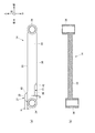
続いて、図5を参照しつつリンク部材14について詳述する。
図5には、一つのリンク部材14のみを拡大して示した。図5(a)にはリンク部材14の平面概略図を示し、図5(b)にはリンク部材14の断面概略図を示している。また、図5における上下方向及び前後方向を示す矢印は、図5(a)についてのみ適用することとする。
図5(a)に示すように、リンク部材14は、平板部33とリンク部34とから成る。平板部33は、細長い略矩形を成す板状部である。リンク部34は、円筒形状を成し、その軸線が左右方向に対して平行又は略平行となるように配置される。平板部33の両端部に2つのリンク部34及び34が形成されている。平板部33とリンク部34とは一体的に形成されている。
一方のリンク部34と他方のリンク部34との間には、平板部33の一対の長辺部位である第1縁辺部35及び第2縁辺部36が形成されている。更に、第1縁辺部35には凸部37が形成され、第2縁辺部36には凹部38が形成されている。凸部37は、最も突出した部位である頂部39と、第1縁辺部35から頂部39に至るまでの徐々に隆起する部位である隆起部40と、から成る。また凹部38は、最も凹んだ部位である底部41と、第2縁辺部36から底部41に至るまでの徐々に陥没する部位である陥没部42と、から成る。
Next, the
FIG. 5 shows only one
As shown in FIG. 5A, the
Between one
なお、図5(a)に示す凸部37の隆起部40は傾斜面によって形成されているが、本発明に係る畦塗り機においては、リンク部材における凸部が縁辺部から直角に立ち上がる垂直面と頂部とから形成されていても良い。同様に、凹部38の陥没部42は傾斜面によって形成されているが、本発明に係る畦塗り機においては、リンク部材における凹部が縁辺部から直角に沈み込む垂直面と底部とから形成されていても良い。
In addition, although the protruding
続いて、図6(a)に示す本実施形態において一対のリンク部材14及び14を採用した場合のサイドカバー13の下端位置と、図6(b)に示す従来の畦塗り機においてリンク部材141に接続されるサイドカバー131の下端位置とを、比較する。
図6(a)においては、上述の畦塗り機1に設けられたサイドカバー13の輪郭線と、一対のリンク部材14及び14とが示されている。また、図6(b)においては、従来の畦塗り機で用いられるサイドカバー131の輪郭線と、一対のリンク部材141及び141とが示されている。
なお、リンク部材の形状以外の条件を揃えるために、サイドカバー13とサイドカバー131とは同一部材であり、一対のリンク部材14及び14、並びに141及び141は同一高さ及び同一間隔となるように取り付けている。
Subsequently, in the present embodiment shown in FIG. 6 (a), the lower end position of the
In Fig.6 (a), the outline of the
In order to make conditions other than the shape of the link member uniform, the
従来例においても、本実施形態においても、サイドカバー131及び13は、元畦及び圃場を耕耘する前処理部に対して、略水平方向に沿った軸線を中心にして回動可能となっている。サイドカバー131及び13は、回動することにより上下方向に変位する。図6(a)及び図6(b)に示すように、サイドカバー13及び131の各回動軌道中の下端位置においては、一対のリンク部材14及び14同士、並びに一対のリンク部材141及び141同士が当接する。
具体的には、図6(a)に示すように、本実施形態におけるサイドカバー13がその回動軌道中の下端に達した時には、下側のリンク部材14の凸部37が、上側のリンク部材14のリンク部34近傍に当接している。
これに対して、図6(b)に示すように、従来におけるサイドカバー131がその回動軌道中の下端に達した時には、一対のリンク部材141及び141の対向するそれぞれの縁辺部同士が当接している。
図6(a)に示す本実施形態と、図6(b)に示す従来例とにおいて、同等の高さまでサイドカバー13及び131を引き上げた後に、サイドカバー13及び131を上方から下方に向かって回動させる場合、図6(a)に示す本実施形態の方が図6(b)に示す従来例に比べて回動軌道中の上方で下端位置に達する。これは、一方のリンク部材14の凸部37が他方のリンク部材14に対して回動途中に干渉することによって、サイドカバー13の回動軌道中における下端位置の方が、サイドカバー131の回動軌道中における下端位置よりも高い位置に規制されることを意味している。
In both the conventional example and the present embodiment, the side covers 131 and 13 are rotatable about an axis along a substantially horizontal direction with respect to the pre-processing unit that plows the base fence and the field. . The side covers 131 and 13 are displaced in the vertical direction by rotating. As shown in FIGS. 6A and 6B, the pair of
Specifically, as shown in FIG. 6 (a), when the
On the other hand, as shown in FIG. 6 (b), when the
In the present embodiment shown in FIG. 6A and the conventional example shown in FIG. 6B, after the side covers 13 and 131 are pulled up to the same height, the side covers 13 and 131 are moved downward from above. In the case of turning, the present embodiment shown in FIG. 6A reaches the lower end position in the upper part of the turning track as compared with the conventional example shown in FIG. 6B. This is because the
更に、図7には、図6に示したリンク部材14及び141のみが、それぞれの回動軌道と共に示されている。図7(a)に二点鎖線にて示したリンク部材14におけるリンク部34の上端位置と、図7(b)に二点鎖線にて示したリンク部材141におけるリンク部341の上端位置とは、同じ高さである。
仮に、リンク部材14に凸部37のみを設けた場合は、リンク部34の上端位置、すなわちリンク部34に接続される前記サイドカバー13の上端位置が、下端位置と同様に規制されることになる。リンク部材14は、一方のリンク部材14に対向する他方のリンク部材14の縁辺部に凹部38を設けている。該凹部38を設けることによって、リンク部材14の回動軌道中の上端に達したときに凸部37が凹部38内に嵌り込むので、上端位置が規制されない。換言すると、凹部38によって、リンク部材14の上側への回動については回動範囲が規制されず、従来の回動範囲を維持することができる。
したがって、縁辺部に凸部37及び凹部38が形成されて成るリンク部材14は、その回動軌道中の上端位置は規制されず、かつ下端位置を規制する事ができるようになっている。
Further, FIG. 7 shows only the
If only the
Accordingly, the
本発明に係る畦塗り機においては、サイドカバーの下端位置の調整は、リンク部材の凸部の突出距離、例えば図6(a)における突出距離Hを調整することによって達成される。例えば、リンク部材における凸部の突出距離を大きくするに従って、サイドカバーの下端位置が高くなる。 In the plastering machine according to the present invention, the lower end position of the side cover is adjusted by adjusting the protruding distance of the convex portion of the link member, for example, the protruding distance H in FIG. For example, the lower end position of the side cover becomes higher as the protruding distance of the convex portion in the link member is increased.
本発明に係るオフセット作業機においては、サイドカバーの上端位置の調整は、リンク部材の凹部の陥没距離、例えば図6(a)における陥没距離Dと、凹部の形状を調整することによって達成される。例えば、リンク部材における凸部が凹部内に完全に嵌り込む程度の陥没距離を有し、かつ凸部の外形に一致する形状又は相似形状を有する凹部を形成することによって、サイドカバーの上端位置が規制されなくなる。
更に、図5(a)に示すように、リンク部材14に凹部38を設ける実施形態を採用する場合、第1縁辺部35に対する隆起部40の傾斜角度と、第2縁辺部36に対する陥没部42の傾斜角度とは、同一又は大きな差異が無い程度であるのが好ましい。このような凹部38を形成することにより、凸部37が凹部38内に嵌まり込み易くなる。これにより、サイドカバー13の上端位置付近の回動動作が円滑になるので好ましい。
In the offset working machine according to the present invention, the adjustment of the upper end position of the side cover is achieved by adjusting the recess distance of the recess of the link member, for example, the recess distance D in FIG. 6A and the shape of the recess. . For example, the upper end position of the side cover is formed by forming a recess having a depression distance such that the protrusion in the link member is completely fitted into the recess and having a shape that matches the outer shape of the protrusion or a similar shape. It will not be regulated.
Further, as shown in FIG. 5A, when the embodiment in which the
図5〜図7に示した本実施形態においてはリンク部材14のリンク部34近傍に凸部37及び凹部38を形成しているが、本発明に係る畦塗り機においては、リンク部材における縁辺部であれば、凸部を設ける位置及び凸部の形状に制限は無い。
凸部の大きさは上述したようにサイドカバーの下端位置の調整に関連するので、本発明に係る畦塗り機の使用環境に応じて要求されるサイドカバーの下端位置に基いた大きさの凸部を決定すれば良い。
凹部を設ける実施形態を採用する場合、凸部の位置、形状及び大きさを決定した上で、凸部の位置、形状及び大きさに合わせて凹部の位置、形状及び大きさを決定すれば良い。
5-7, the
Since the size of the convex portion is related to the adjustment of the lower end position of the side cover as described above, the convex portion having a size based on the lower end position of the side cover required in accordance with the use environment of the coater according to the present invention. What is necessary is just to determine a part.
When the embodiment in which the concave portion is provided is adopted, the position, shape, and size of the convex portion are determined, and then the position, shape, and size of the concave portion are determined in accordance with the position, shape, and size of the convex portion. .
本実施形態においては、一対のリンク部材14のいずれにも同一形状及び同一寸法の凸部及び凹部を同位置に設けることにより、同一部材のリンク部材14を2つ用いている。これにより、前処理部24及びサイドカバー13に対する一対のリンク部材14及び14の取付順、取付方向等を考慮する必要が無くなるので好ましい。
In the present embodiment, two
リンク部材の縁辺部に直交する方向の幅を、本発明に係る畦塗り機におけるリンク部材の凸部の突出距離と同程度大きくすることによって、凸部を設けなくともサイドカバーの下端位置の規制は可能である。
しかしながら、幅の大きなリンク部材はリンク部材同士の取付間隔を従来よりも大きく取る必要が生じるだけでなく、オフセット作業機におけるリンク部材の占有領域が大きくなってしまう。更に、リンク部材の重量が大きくなるので、リンク部材と前処理体との連結手段、及びリンク部材とサイドカバーとの連結手段として高い強度が要求されることになり、連結手段による連結部位の保守点検の工程も必要となり得る。
また、凸部を有するリンク部材に比べて、幅の大きなリンク部材は、リンク部材の製造により多くの材料を要する。
Restricting the lower end position of the side cover without providing a convex portion by increasing the width in the direction perpendicular to the edge portion of the link member to the same extent as the protruding distance of the convex portion of the link member in the coater according to the present invention. Is possible.
However, the link member having a large width not only needs to have a larger attachment interval between the link members than the conventional one, but also increases the area occupied by the link member in the offset working machine. Further, since the weight of the link member is increased, high strength is required as a connection means between the link member and the pretreatment body and a connection means between the link member and the side cover, and maintenance of the connection portion by the connection means is required. An inspection process may also be required.
In addition, a link member having a larger width than a link member having a convex portion requires more material for manufacturing the link member.
本発明に係る畦塗り機におけるリンク部材は、少なくとも凸部が形成されているので、サイドカバーの回動軌道中の下端位置を規制可能となっている。つまり、単純な構造でありながらサイドカバーの下げ位置を規制することができ、複雑で部品点数の多いサイドカバー下げ位置規制機構が不要となる。また、サイドカバーの下端位置を畦塗り作業の天場の高さに規制することにより、整畦前に元畦及び圃場を耕耘する際の土の飛散が好適に防止することができる。 Since at least the convex part is formed in the link member in the coater according to the present invention, the lower end position of the side cover in the turning track can be regulated. That is, although the structure is simple, the side cover lowering position can be restricted, and a complicated side cover lowering position restriction mechanism with a large number of parts is not required. Moreover, by restricting the lower end position of the side cover to the height of the top of the padding work, it is possible to suitably prevent the scattering of soil when plowing the main paddle and the field before trimming.
以上、本発明者によってなされた発明を適用した実施形態について説明したが、この実施形態による本発明の開示の一部をなす論述及び図面により、本発明は限定されることはない。すなわち、この実施形態に基づいて当業者等によりなされる他の実施形態、実施例及び運用技術等は全て本発明の範疇に含まれることは勿論であることを付け加えておく。 As mentioned above, although embodiment which applied the invention made | formed by this inventor was described, this invention is not limited by the description and drawing which make a part of indication of this invention by this embodiment. That is, it should be added that other embodiments, examples, operation techniques, and the like made by those skilled in the art based on this embodiment are all included in the scope of the present invention.
1:畦塗り機、2:装着部、3:連結部、4:作業部、5:動力伝達部、61:第1伸縮シリンダ、62:第2伸縮シリンダ、7:駆動用シャフト、8:オフセットフレーム、9:リンクロッド、10:支持フレーム、11:前処理体、12:整畦体、13:サイドカバー、14:リンク部材、15:作業部支持体、16:縦筒部、17:横筒部、18:入力軸、19:環状チェーン、20:中継軸、21:第1出力軸、22:第2出力軸、23:天場処理部、24:前処理部、25:回転軸、26:天場用耕耘爪、27:上下位置調節部、28:耕耘爪、29:天場用動力伝達部、30:円錐ドラム、31:円筒部、32:整畦用動力伝達部、33:平板部、34:リンク部、35:第1縁辺部、36:第2縁辺部、37:凸部、38:凹部、39:頂部、40:底部、41:底部、42:陥没部、50:耕耘用回転軸、51:作業フレーム、100:走行機体、H:突出距離、D:陥没距離
1: coating machine, 2: mounting part, 3: connecting part, 4: working part, 5: power transmission part, 61: first telescopic cylinder, 62: second telescopic cylinder, 7: driving shaft, 8: offset Frame: 9: Link rod, 10: Support frame, 11: Pretreatment body, 12: Adjusting body, 13: Side cover, 14: Link member, 15: Working part support body, 16: Vertical cylinder part, 17: Horizontal Tube portion, 18: input shaft, 19: annular chain, 20: relay shaft, 21: first output shaft, 22: second output shaft, 23: heaven processing section, 24: preprocessing section, 25: rotating shaft, 26: Tillage claw, 27: Vertical position adjustment unit, 28: Claw claw, 29: Power transmission unit for heaven, 30: Conical drum, 31: Cylindrical part, 32: Power transmission unit for rectification, 33: Flat plate part, 34: link part, 35: first edge part, 36: second edge part, 37: convex part, 38: concave part , 39: top, 40: bottom, 41: bottom, 42: recess, 50: tilling rotary shaft, 51: working frame, 100: vehicle body, H: protrusion distance, D: depression distance
Claims (4)
前記前処理体より後方に設けられ、前記前処理体により耕耘された土を畦として成形する整畦体と、
前記前処理体の左右方向外側に設けられて、耕耘時に土の飛散を防止するサイドカバーと、を備える畦塗り機であって、
前記前処理体に対して前記サイドカバーを上下方向へ回動可能に連結する一対のリンク部材を有し、
前記一対のリンク部材は、間隙を設けて平行に配置され、
前記一対のリンク部材の一方に、前記間隙に向かって凸部が形成されている、
畦塗り機。 A pre-treatment body that is attached to the rear of the traveling machine body, receives power from the traveling machine body, plows the main fence and the field, and raises the soil in a bowl shape;
A trimming body that is provided behind the pretreatment body and molds the soil cultivated by the pretreatment body as a ridge,
A side coater provided on the outer side in the left-right direction of the pretreatment body and including a side cover that prevents scattering of soil during tillage,
A pair of link members that connect the side cover to the pretreatment body so as to be rotatable in the vertical direction;
The pair of link members are arranged in parallel with a gap between them,
A convex portion is formed on one of the pair of link members toward the gap.
畦 coating machine.
請求項1に記載の畦塗り機。 On the other side of the pair of link members, a recess is formed into which the projection fits when the pair of link members reach the upper end in each of the rotating tracks.
The lacquering machine according to claim 1.
一方のリンク部材に形成された凸部が前記凸部であり、他方のリンク部材に形成された凹部が前記凹部である、
請求項2に記載の畦塗り機。 A convex portion and a concave portion are formed in each of the pair of link members so that one link member and the other link member have the same shape,
The convex portion formed on one link member is the convex portion, and the concave portion formed on the other link member is the concave portion,
The wrinkle coater according to claim 2.
請求項1〜3のいずれか一項に記載の畦塗り機。
The lower end position in the rotation trajectory of the pair of link members is a position where the side cover comes into contact with or is close to the soil raised by the pretreatment body.
The glazing machine according to any one of claims 1 to 3.
Priority Applications (1)
| Application Number | Priority Date | Filing Date | Title |
|---|---|---|---|
| JP2013146756A JP6139309B2 (en) | 2013-07-12 | 2013-07-12 | 畦 coating machine |
Applications Claiming Priority (1)
| Application Number | Priority Date | Filing Date | Title |
|---|---|---|---|
| JP2013146756A JP6139309B2 (en) | 2013-07-12 | 2013-07-12 | 畦 coating machine |
Publications (2)
| Publication Number | Publication Date |
|---|---|
| JP2015015936A true JP2015015936A (en) | 2015-01-29 |
| JP6139309B2 JP6139309B2 (en) | 2017-05-31 |
Family
ID=52437619
Family Applications (1)
| Application Number | Title | Priority Date | Filing Date |
|---|---|---|---|
| JP2013146756A Active JP6139309B2 (en) | 2013-07-12 | 2013-07-12 | 畦 coating machine |
Country Status (1)
| Country | Link |
|---|---|
| JP (1) | JP6139309B2 (en) |
Cited By (2)
| Publication number | Priority date | Publication date | Assignee | Title |
|---|---|---|---|---|
| JP2018102225A (en) * | 2016-12-27 | 2018-07-05 | 小橋工業株式会社 | Mower |
| JP2020188722A (en) * | 2019-05-22 | 2020-11-26 | 松山株式会社 | Levee plastering machine |
Citations (4)
| Publication number | Priority date | Publication date | Assignee | Title |
|---|---|---|---|---|
| JPS62107605U (en) * | 1985-12-27 | 1987-07-09 | ||
| JPH10215626A (en) * | 1997-02-06 | 1998-08-18 | Yanmar Agricult Equip Co Ltd | Rice transplanter |
| JP2002125406A (en) * | 2000-10-25 | 2002-05-08 | Kobashi Kogyo Co Ltd | Border coating machine |
| JP2012044884A (en) * | 2010-08-25 | 2012-03-08 | Matsuyama Plow Mfg Co Ltd | Offset working machine |
-
2013
- 2013-07-12 JP JP2013146756A patent/JP6139309B2/en active Active
Patent Citations (4)
| Publication number | Priority date | Publication date | Assignee | Title |
|---|---|---|---|---|
| JPS62107605U (en) * | 1985-12-27 | 1987-07-09 | ||
| JPH10215626A (en) * | 1997-02-06 | 1998-08-18 | Yanmar Agricult Equip Co Ltd | Rice transplanter |
| JP2002125406A (en) * | 2000-10-25 | 2002-05-08 | Kobashi Kogyo Co Ltd | Border coating machine |
| JP2012044884A (en) * | 2010-08-25 | 2012-03-08 | Matsuyama Plow Mfg Co Ltd | Offset working machine |
Cited By (3)
| Publication number | Priority date | Publication date | Assignee | Title |
|---|---|---|---|---|
| JP2018102225A (en) * | 2016-12-27 | 2018-07-05 | 小橋工業株式会社 | Mower |
| JP2020188722A (en) * | 2019-05-22 | 2020-11-26 | 松山株式会社 | Levee plastering machine |
| JP7141713B2 (en) | 2019-05-22 | 2022-09-26 | 松山株式会社 | ridge coating machine |
Also Published As
| Publication number | Publication date |
|---|---|
| JP6139309B2 (en) | 2017-05-31 |
Similar Documents
| Publication | Publication Date | Title |
|---|---|---|
| KR101804684B1 (en) | Multiple work machine for rotor cultivators | |
| JP2012029608A (en) | Walking type cultivator | |
| KR20200044657A (en) | Cultivator with harrow | |
| JP6139309B2 (en) | 畦 coating machine | |
| JP2007300804A (en) | Agricultural implement | |
| JP5709297B2 (en) | Agricultural machine | |
| KR101423951B1 (en) | Variable farm tractor disk plow | |
| JP6386482B2 (en) | Rotary tiller skid equipment | |
| JP5000311B2 (en) | Pricking machine | |
| JP6180966B2 (en) | 2-axis rotary tiller | |
| JP5988819B2 (en) | Agricultural machine | |
| JP2008161061A (en) | Power tiller | |
| JP4031224B2 (en) | Takatsuki forming work machine and Takatsuki forming plate used therefor | |
| JP4330891B2 (en) | 畦 coating machine | |
| JP4318987B2 (en) | 畦 coating machine | |
| JP2005130715A (en) | Apparatus for eliminating ditch of chain transmission case | |
| JP6149513B2 (en) | 畝 Forming equipment | |
| JP2569100Y2 (en) | Rotary cultivator | |
| JP3209949B2 (en) | Row coating machine | |
| RU2259698C1 (en) | Combined tillage tool | |
| JP2021061761A (en) | Puddling work machine | |
| JP4545057B2 (en) | Rotary tillage device | |
| JP2016192949A (en) | Tillage claw | |
| JP2004008185A (en) | Leveling plate-supporting device of rotary plowing unit | |
| JPH0928118A (en) | Land grading plate for simultaneous tilling transplanter |
Legal Events
| Date | Code | Title | Description |
|---|---|---|---|
| A621 | Written request for application examination |
Free format text: JAPANESE INTERMEDIATE CODE: A621 Effective date: 20160608 |
|
| A131 | Notification of reasons for refusal |
Free format text: JAPANESE INTERMEDIATE CODE: A131 Effective date: 20170221 |
|
| A977 | Report on retrieval |
Free format text: JAPANESE INTERMEDIATE CODE: A971007 Effective date: 20170222 |
|
| A521 | Request for written amendment filed |
Free format text: JAPANESE INTERMEDIATE CODE: A523 Effective date: 20170321 |
|
| TRDD | Decision of grant or rejection written | ||
| A01 | Written decision to grant a patent or to grant a registration (utility model) |
Free format text: JAPANESE INTERMEDIATE CODE: A01 Effective date: 20170418 |
|
| A61 | First payment of annual fees (during grant procedure) |
Free format text: JAPANESE INTERMEDIATE CODE: A61 Effective date: 20170427 |
|
| R150 | Certificate of patent or registration of utility model |
Ref document number: 6139309 Country of ref document: JP Free format text: JAPANESE INTERMEDIATE CODE: R150 |
|
| R250 | Receipt of annual fees |
Free format text: JAPANESE INTERMEDIATE CODE: R250 |
|
| R250 | Receipt of annual fees |
Free format text: JAPANESE INTERMEDIATE CODE: R250 |