JP2015015170A - Illumination lamp and lighting device including the same - Google Patents
Illumination lamp and lighting device including the same Download PDFInfo
- Publication number
- JP2015015170A JP2015015170A JP2013141565A JP2013141565A JP2015015170A JP 2015015170 A JP2015015170 A JP 2015015170A JP 2013141565 A JP2013141565 A JP 2013141565A JP 2013141565 A JP2013141565 A JP 2013141565A JP 2015015170 A JP2015015170 A JP 2015015170A
- Authority
- JP
- Japan
- Prior art keywords
- housing
- illumination lamp
- fin
- light source
- casing
- Prior art date
- Legal status (The legal status is an assumption and is not a legal conclusion. Google has not performed a legal analysis and makes no representation as to the accuracy of the status listed.)
- Pending
Links
- 238000005286 illumination Methods 0.000 title claims abstract description 115
- 230000002093 peripheral effect Effects 0.000 claims abstract description 11
- 239000011347 resin Substances 0.000 claims description 13
- 229920005989 resin Polymers 0.000 claims description 13
- 229910052751 metal Inorganic materials 0.000 claims description 4
- 239000002184 metal Substances 0.000 claims description 4
- 239000000835 fiber Substances 0.000 claims description 2
- 230000000694 effects Effects 0.000 description 15
- 230000006870 function Effects 0.000 description 10
- 239000000463 material Substances 0.000 description 10
- 230000004048 modification Effects 0.000 description 10
- 238000012986 modification Methods 0.000 description 10
- 230000035807 sensation Effects 0.000 description 9
- 239000000758 substrate Substances 0.000 description 7
- 239000007769 metal material Substances 0.000 description 6
- 238000000034 method Methods 0.000 description 6
- XEEYBQQBJWHFJM-UHFFFAOYSA-N Iron Chemical compound [Fe] XEEYBQQBJWHFJM-UHFFFAOYSA-N 0.000 description 4
- 229910000831 Steel Inorganic materials 0.000 description 4
- 239000000919 ceramic Substances 0.000 description 4
- 230000017525 heat dissipation Effects 0.000 description 4
- -1 polybutylene terephthalate Polymers 0.000 description 4
- 239000010959 steel Substances 0.000 description 4
- 230000005494 condensation Effects 0.000 description 3
- 238000009833 condensation Methods 0.000 description 3
- 229920000515 polycarbonate Polymers 0.000 description 3
- 239000004417 polycarbonate Substances 0.000 description 3
- 229910052782 aluminium Inorganic materials 0.000 description 2
- XAGFODPZIPBFFR-UHFFFAOYSA-N aluminium Chemical compound [Al] XAGFODPZIPBFFR-UHFFFAOYSA-N 0.000 description 2
- 239000011231 conductive filler Substances 0.000 description 2
- 238000010586 diagram Methods 0.000 description 2
- 239000011521 glass Substances 0.000 description 2
- 239000011810 insulating material Substances 0.000 description 2
- 229910052742 iron Inorganic materials 0.000 description 2
- 229920001707 polybutylene terephthalate Polymers 0.000 description 2
- 229920000139 polyethylene terephthalate Polymers 0.000 description 2
- 239000005020 polyethylene terephthalate Substances 0.000 description 2
- 239000002994 raw material Substances 0.000 description 2
- XLYOFNOQVPJJNP-UHFFFAOYSA-N water Substances O XLYOFNOQVPJJNP-UHFFFAOYSA-N 0.000 description 2
- NIXOWILDQLNWCW-UHFFFAOYSA-N acrylic acid group Chemical group C(C=C)(=O)O NIXOWILDQLNWCW-UHFFFAOYSA-N 0.000 description 1
- 239000003990 capacitor Substances 0.000 description 1
- 238000001816 cooling Methods 0.000 description 1
- 230000007423 decrease Effects 0.000 description 1
- 238000001514 detection method Methods 0.000 description 1
- 238000009792 diffusion process Methods 0.000 description 1
- 230000004907 flux Effects 0.000 description 1
- 230000006872 improvement Effects 0.000 description 1
- 238000012538 light obscuration Methods 0.000 description 1
- 238000000465 moulding Methods 0.000 description 1
- 229920001778 nylon Polymers 0.000 description 1
- 230000008569 process Effects 0.000 description 1
- 230000001737 promoting effect Effects 0.000 description 1
- 230000005855 radiation Effects 0.000 description 1
- 230000009467 reduction Effects 0.000 description 1
- 230000001629 suppression Effects 0.000 description 1
Images


Abstract
Description
本発明は、照明ランプ及びそれを備えた照明装置に関するものである。 The present invention relates to an illumination lamp and an illumination device including the illumination lamp.
照明ランプは、たとえばLEDなどの光源、光源を駆動するのに利用される点灯回路、及び、光源及び点灯回路などを収容する筐体などを有しているものである。この照明ランプが発光すると、光源及び点灯回路から発生する熱によって筐体の温度が上昇する。たとえば、ユーザーは、照明ランプの所定使用期間が満了した時点あるいは満了を控えた時点において、照明ランプを消灯直後に交換する場合に、照明装置から照明ランプを取り外すために筐体に触れることとなるが、この際、筐体が冷却していないと、ユーザーが不快に感じる場合がある。また、筐体が高い温度を維持していると、ユーザーは照明ランプの取り替えにあたり、筐体に触れることができない。 The illumination lamp has, for example, a light source such as an LED, a lighting circuit used for driving the light source, and a housing that houses the light source and the lighting circuit. When the illumination lamp emits light, the temperature of the housing rises due to heat generated from the light source and the lighting circuit. For example, when the predetermined usage period of the illumination lamp expires or when the user refrains from expiring, the user touches the housing to remove the illumination lamp from the illumination device when the illumination lamp is replaced immediately after it is turned off. However, at this time, if the casing is not cooled, the user may feel uncomfortable. In addition, if the casing maintains a high temperature, the user cannot touch the casing when replacing the illumination lamp.
そこで、ユーザーが照明ランプの筐体に触れても熱さを感じにくくするように構成した照明ランプが提案されている(たとえば、特許文献1参照)。特許文献1に記載の技術は、「装置本体3の熱伝導率よりも小さい熱伝導率を有し、装置本体3の一端側7aにまたは装置本体3とグローブ5とに跨って設けられ、かつ装置本体3の最大外径部16より外側に突出するように装置本体3の外周面7cに沿って設けられた環状体6」を有する照明ランプに関するものである。
In view of this, there has been proposed an illumination lamp configured to make it difficult for the user to feel heat even when the user touches the housing of the illumination lamp (see, for example, Patent Document 1). The technique described in
特許文献1に記載の技術は、装置本体(筐体)よりも熱伝導率を小さくした環状体を有している照明ランプに関するものであるが、環状体はグローブと装置本体(筐体)との接続位置近傍に部分的に設置されているものである。このため、ユーザーの手指が、環状体を設置した領域を外れて高温の筐体に触れてしまい、不快感を与える可能性があったり、筐体の温度が高くて筐体に触れることができず、照明ランプの取り替えをすることができなかったりする。
また、環状体は装置本体(筐体)よりも熱伝導率を小さくしており、特に光源から発生する熱を放熱する効率を低下させてしまい、動作品質を低下させてしまうおそれがある。
The technique described in
In addition, the annular body has a lower thermal conductivity than the apparatus main body (housing), and in particular, the efficiency of radiating the heat generated from the light source is lowered, and the operation quality may be lowered.
本発明は、以上のような課題を解決するためになされたもので、照明ランプの交換時における利便性が向上する照明ランプ及びそれを備えた照明装置を提供することを目的としている。 The present invention has been made to solve the above-described problems, and an object of the present invention is to provide an illumination lamp that improves convenience when the illumination lamp is replaced, and an illumination device including the illumination lamp.
本発明に係る照明ランプは、筒状の筐体と、筐体の一端側に接続される口金部と、筐体の他端側に設けられる光源と、筐体に収容され、口金部を経由して供給される商用電力を光源の駆動に利用される駆動電力に変換して光源に供給する点灯回路と、筐体の外側に設けられ、筐体の外周面積よりも面積が小さい握持部材と、を備えたものである。 An illumination lamp according to the present invention includes a cylindrical casing, a base connected to one end of the casing, a light source provided on the other end of the casing, and a casing that is accommodated in the casing. A lighting circuit that converts commercial power supplied to drive power used to drive the light source and supplies the light to the light source, and a gripping member that is provided outside the housing and has a smaller area than the outer peripheral area of the housing And.
本発明に係る照明ランプによれば、上記構成を有しているため、照明ランプの交換時などにおける利便性が向上する。 Since the illumination lamp according to the present invention has the above-described configuration, the convenience when replacing the illumination lamp is improved.
実施の形態1.
はじめに、本実施の形態の説明に使用する図面について略述する。
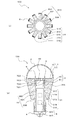
図1は、実施の形態1に係る照明ランプ100の概要構成例図である。図2は、実施の形態1に係る照明ランプ100の断面図である。図2(a)は照明ランプ100の筐体3cを通る部分における水平断面図である。また、図2(b)は照明ランプ100の縦断面図である。
First, the drawings used for explaining the present embodiment will be outlined.
FIG. 1 is a schematic configuration example diagram of an
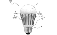
本実施の形態に係る照明ランプ100は、照明ランプ100の交換時における利便性を向上させる改良が加えられたものである。照明ランプ100は、光源1、グローブ2、筐体3、口金部4、及び点灯回路5を有する電球形の照明ランプである。
The
(光源1)
光源1は、発光手段であるLED10と、LED10が実装されるLED基板11とを備えている。光源1の構成要素には、LED10及びLED基板11のほか、点灯回路5と電気的に接続され駆動電力を点灯回路5から光源1に伝達するワイヤーハーネス及びコネクタなどの配線部材(図示せず)、及び照明ランプ100の設計仕様に応じて必要となる電子部品などが含まれる。なお、本実施の形態1では、LED10を採用する場合を例に説明するが、たとえば、レーザーダイオード、有機EL、及び蛍光ランプなどを採用してもよい。
(Light source 1)
The
光源1は、筐体3のうち口金部4が嵌合されている側とは反対側の端面に取り付けられているものである。そして、光源1は、光源1の出射面がグローブ2によって覆われている。LED基板11及び後述する第2の筐体部31の取付面部317には、ネジ9が挿入される開口700及び開口701が形成されている。そして、LED基板11は、後述する第1の筐体部30の第1ボス部303及び第2ボス部304の開口に挿入され、筐体3にねじ込まれるネジ9によって固定される。なお、LED基板11及び第2の筐体部31に形成された開口700及び開口701は、貫通孔であり、ネジ9がねじ込まれるネジ受けとして機能するものではなく、第1の筐体部30の第1ボス部303及び第2ボス部304が、ネジ9がねじ込まれるネジ受けとして機能している。また、LED基板11及び後述する第2の筐体部31の取付面部317には、開口700及び開口701に加えて、開口702が形成されている。この開口702は、点灯回路5より光源1に供給される駆動電力を伝送する配線などを、第2の筐体部31側の空間からLED基板11側に取り出すのに利用されるものである。
The
(グローブ2)
グローブ2は、光源1から出射される光が透過する(透光性を有する)、たとえばガラス、樹脂などの素材で構成され、光源1から出射される光の出射側を覆うように配設されている。グローブ2を構成する樹脂としては、たとえばポリカーボネート、アクリルなどが製品仕様に応じて選択される。グローブ2は、図1の例では、外形が曲面形状でいわゆる下方向光束型である。グローブ2は、透光性を有し光源1から出射される光を透過させるとともに、照明ランプ100の仕様に応じて、光を拡散、集光、反射させる機能を併せ持つ。これらの機能は、グローブ2の基材であるガラス又は樹脂を成形する際に拡散層(あるいは面)、レンズ、反射層(あるいは面)などを形成して基材自身で直接的に実現してもよいし、基材の表面にそれらの機能を実現する別部材を組み合わせて構成してもよい。
(Glove 2)
The
(口金部4)
口金部4は、一端が照明装置150(たとえば、図4を参照)のソケット160に螺合する構造を有しており、照明装置150を経由して商用電力を照明ランプ100に入力する入力端である。商用電力は口金部4を介して点灯回路5に供給される。また、口金部4の他端は螺合構造を有しており、筐体3に螺合される。
(Base 4)
The
(点灯回路5)
点灯回路5は、回路基板500及び回路基板500に取り付けられる回路部品501を有しているものである。なお、回路部品501は、たとえばスイッチング素子、インダクタ、電解コンデンサなどに対応するものである。点灯回路5は、商用電力である交流からLED10を点灯させる直流に変換するAC−DCコンバータ回路を有する。点灯回路5は、筐体3の内部に収容され、口金部4を経由して供給される商用電力を光源1の点灯に利用される駆動電力に変換して光源1に供給する。好ましくは、点灯回路5は、LED10を安定的に点灯させるために、負荷変動の検出機能、負荷変動に応じてAC−DCコンバータ回路から出力される点灯電流を制御する制御機能、商用電力の供給経路を介して流入、流出するノイズを低減するフィルタ機能などをさらに有する。
(Lighting circuit 5)
The
(筐体3)
筐体3は円筒状をなし、内部に点灯回路5を収納する第1の筐体部30と、第1の筐体部30の外側に取り付けられる第2の筐体部31とを備える。第1の筐体部30は、絶縁性の素材で構成されるものである。第1の筐体部30は、たとえば、ポリカーボネート、ポリブチレンテレフタレート、ポリエチレンテレフタレートなどの樹脂素材、セラミックなどから構成される。第2の筐体部31は、熱伝導性の素材で構成されるものである。第2の筐体部31は、たとえば、鉄、アルミニウムなどの金属素材、熱伝導フィラーなどを混合したセラミックなどから構成されるものである。第1の筐体部30及び第2の筐体部31を有する筐体3とグローブ2、さらに第1の筐体部30に接続される口金部4とが組み合わさると、これらは全体として電球形照明ランプの外形をなす。
なお、本実施の形態1では、第1の筐体部30が樹脂で構成され、第2の筐体部31が金属で構成される場合を例に説明するが、それに限定されるものではなく、たとえば、第1の筐体部30が金属で構成され、第2の筐体部31が樹脂で構成されていてもよい。また、両方とも樹脂で構成してもよいし、両方とも金属で構成してもよい。
(Case 3)
The
In the first embodiment, the case where the
本実施の形態1における第1の筐体部30は、第2の筐体部31とは異なり、後述する第2のフィン部315に対応するフィン部を備えない点が異なる。
第1の筐体部30は一端側に口金部4が接続される。第1の筐体部30は、内部に点灯回路5を収容する空間を有するとともに、第1の筐体部30の他端側に点灯回路5を第1の筐体部30内に収容する際に利用される開口部90が形成されている。第1の筐体部30の内部には、点灯回路5が有する回路部品501の回路基板500を保持する保持構造(図示省略)が形成されている。第1の筐体部30の筒部306の内側面300と、点灯回路5が具備する回路部品501との間には、保持構造によって保持される回路基板500を除いて、予め設定された量の間隙が形成されている。つまり、回路部品501に機械的応力が加わらないように、第1の筐体部30は、点灯回路5を第1の筐体部30の内部空間に内包保持している。
The
The
第1の筐体部30は、一端側に口金部4が螺合される螺合構造を略円筒状に形成された筒部306を有している。ここで、筒部306は略円筒状の他に角筒状に形成されていてもよい。また、筒部306と口金部4との接続は螺合以外の方法でもよい。
The
筒部306には、他端側に点灯回路5を第1の筐体部30内に収容する際に利用される開口部90が形成されている。開口部90近傍の筒部306の内側面300には、筒部306の中心軸方向に第1ボス部303及び第2ボス部304が形成されている。本実施の形態1では、筒部306の中心軸を挟んで、第1ボス部303と第2ボス部304とが対向するように形成されている。第1ボス部303及び第2ボス部304には、ネジ9がねじ込まれる孔が形成されており、ネジ受けとしての機能を有している。ネジ9が第1ボス部303及び第2ボス部304にねじ込まれることで第1の筐体部30と第2の筐体部31とが固定される。
The
第2の筐体部31は、第1の筐体部30の口金部4と螺合される一端側と反対側の所定部分を収容するように設けられている。第2の筐体部31は、光源1が取り付けられる面が形成された平面状の取付面部317と、取付面部317側から第1の筐体部30側に向かって延出するように形成された円筒状の筒部316と、筒部316の外側面314から筒部316の径方向の外側に向かって突出するように形成された第2のフィン部315とを有している。ここで、本実施の形態1において、取付面部317は円板状に形成されており、筒部316は円筒状に形成されているが、これらの形状に限定されるものではない。
The
筒部316は、その内側面313が第1の筐体部30の筒部306の外側面301と当接するように設けられ、その外側面314から放射状に突出形成された複数の第2のフィン部315が形成されている。第2のフィン部315の数、放射方向の高さ、周方向の厚さは、照明ランプの設計仕様に応じて決定される。
The
(起毛部6)
図1を参照して、筐体3の外周面は、照明装置から照明ランプ100を取り外すためにユーザーが手指を触れる握持部となる。本実施の形態1では、放射状に突出形成された複数の第2のフィン部315の外側面318が握持部として機能する。すなわち、握持部とは、筐体3の外側面のうちの第2のフィン部315の外側面318に対応するものである。起毛部6は、握持部材を構成するものである。この起毛部6は、握持部(外側面318)に設けられているものであり、筐体3の筒部316の外周面積よりも面積が小さいものである。
(Raised part 6)
With reference to FIG. 1, the outer peripheral surface of the housing | casing 3 becomes a holding part which a user touches a finger in order to remove the
筒部316の外側面314と第2のフィン部315の外側面318との間には、放熱に伴う温度勾配(熱勾配)があり、第2のフィン部315の外側面318の温度は、筒部316の外側面314の温度よりも低くなっている。しかし触感温度としては高い水準である。
外側面318には、口金部4側の端部から光源1側の端部にかけて、触感温度を低減する起毛部6が配設されている。外側面318と起毛部6の外面(起毛の先端部)との間には、放熱に伴う温度勾配があり、起毛部6の外面(起毛の先端部)の温度は、第2のフィン部315の外側面318の温度よりも更に低い温度となる。すなわち、筐体の外周部(第2のフィン部315の外側面318)から起毛部6に向かうにしたがって温度が低くなるような熱勾配が形成されるということである。なお、放射状に形成された第2のフィン部315の外側面318に起毛部6が設けられているので、この温度勾配は、筐体3に対して略放射状となるように形成されることとなる。
また、起毛部6の外面(起毛の先端部)の面積は極小であり、手指と接触して手指に熱伝達が可能となる面積が小さい。すなわち、ユーザーの手指が、起毛部6及び筐体3の外周部である外側面318に触れたときにおいて、外側面318よりも起毛部6の方が接触面積が小さく、触感温度を低減することができる。
また、起毛部6が配設されると放熱面積が増加するので、照明ランプ100を点灯動作させているときに、第2の筐体部31の冷却(放熱)を促進させる効果も奏する。すなわち、光源1や点灯回路5の動作品質を向上させることができる。
There is a temperature gradient (thermal gradient) associated with heat dissipation between the
On the
Further, the area of the outer surface of the raised portion 6 (the raised end portion of the raised portion) is extremely small, and the area where heat can be transferred to the finger by contact with the finger is small. That is, when the user's finger touches the raised
Moreover, since the heat dissipation area increases when the raised
ここで、起毛部6には、たとえば、静電植毛、植毛鋼板などを採用するとよい。静電植毛及び植毛鋼板とは、たとえばナイロン繊維などの繊維を、ある部材の表面に複数形成する加工を施すことをいう。このような静電植毛、植毛鋼板などを施すと、部材の表面を起毛させることができ、触感温度の低減、摩擦の増大、及び結露抑制などの効果を得ることができるものである。なお、本実施の形態1では、静電植毛、植毛鋼板を利用して起毛部6に起毛構造を具備させたものとして説明するが、起毛構造を備えるものであればよく、公知の手法を用いることができる。
Here, for the raised
起毛部6は、起毛していることによって、ユーザーの手指との摩擦が大きくなり、ユーザーが筐体3を握持した状態で照明ランプを交換する際に、滑ってしまうことを抑制する効果を有している。すなわち、ユーザーは照明ランプ100の交換を確実に行うことができ、誤って照明ランプ100を落下させてしまうことを防止することができる。
また、起毛部6が設けられた外側面318は、結露が生じにくくなっており、室内などに水滴が滴下してユーザーの快適性を損ねることを抑制することができる。
さらに、照明ランプ100の起毛部6が設けられた外側面318以外の部分に、結露が生じた場合には、起毛部6が水分を吸収し保持するため、室内などに水滴が滴下したり、筐体3とグローブ2との接続部の隙間から照明ランプ100内部に水分が浸入したりすることを抑制することができる。
The raised
In addition, the
Furthermore, when dew condensation occurs in a portion other than the
[実施の形態1の第1変形例]
図3は、図1に示す照明ランプ100の第1変形例(照明ランプ100a)である。図3に示す照明ランプ100aは、照明ランプ100のグローブ2及び筐体3とは形状が異なるグローブ2a及び筐体3aを有するものである。
グローブ2aは、図1に示すグローブ2とは異なり、略球状の形状をなしているものでいわゆる全方向光束型ある。また、筐体3aの第1の筐体部30a及び第2の筐体部31aは、筐体3よりも、口金部4側からグローブ2側にかけての寸法が短くなっている。このような照明ランプ100aでは、グローブ2aと筐体3aとの接続部近傍が、グローブ2aの最大径よりも縮径しているため、ユーザーが握持しにくい形状となっている。このような照明ランプ100aであっても外側面318aの口金部4側の端部から光源1側の端部にかけて、触感温度を低減する起毛部6aが設けられているので、実施の形態1の照明ランプ100と同様の効果を得ることができる。
[First Modification of First Embodiment]
FIG. 3 shows a first modification (
Unlike the
[照明ランプ100、100aが有する効果]
照明ランプ100、100aは、第2の筐体部31、31aの第2のフィン部315、315aに起毛部6、6aを設けたので、触感温度を抑制することができる。これにより、ユーザーに熱さを感じさせることを抑制することができるため、たとえば照明ランプ100、100aを消灯直後に交換することができ、ユーザーの利便性が向上する。
[Effects of the
Since the
本実施の形態1に係る照明ランプ100、100aは、起毛部6、6aが、第2の筐体部31、31aの第2のフィン部315、315aの外側面318、318aのうち、口金部4側の端部側から光源1側の端部側にかけて全域に配設されている場合を例に説明したが、それに限定されるものではない。
たとえば、起毛部6、6aは、部分的に配設されていても同様の効果を得ることができる。ただし、第2のフィン部315、315aの外側面318、318aの全域に配設されている方が、よりユーザーの触感温度を抑制することができる。
In the
For example, even if the raised
また、起毛部6、6aは、第2の筐体部31、31aの第2のフィン部315、315aの外側面318、318aの全てに設けられていなくてもよい。ただし、全ての第2のフィン部315、315aに起毛部6、6aが配設されている方が、よりユーザーの触感温度を抑制することができる。
Further, the raised
本実施の形態1に係る照明ランプ100、100aは、起毛部6、6aが、第2の筐体部31、31aの第2のフィン部315、315aの外側面318、318aに設けられている場合を例に説明したが、それに限定されるものではない。
たとえば、第2のフィン部315、315aのうち外側面318、318aに直交する面であって第2のフィン部315どうし、315aどうしが対向する面などに起毛部6が設けられていてもよい。また、筒部316、316aの外側面に起毛部6、6aが設けられていてもよい。これによっても、本実施の形態1に係る照明ランプ100、100aと同様の効果を得ることができる。
In the
For example, the raised
[実施の形態1の第2変形例]
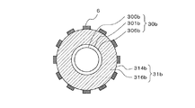
図4は、図1に示す照明ランプ100の第2変形例である。なお、図4は、図2(a)と同様に水平断面図である。図1及び図2に示す照明ランプ100、100aは、いずれも第2の筐体部31、31aに第2のフィン部315、315aが形成され、第2のフィン部315、315aの外側面318、318aに起毛部6が形成されている。これらに対して、第2変形例は、第2筐体部31bに第2のフィン部315、315aを備えず、起毛部6が第2筐体部31bの外側面314bに設けられている点で、異なるものである。このような、照明ランプ100bであっても照明ランプ100、100aと同様の効果を得ることができる。また、外側面314bはフィン部を備えず滑らかな面で形成されるため、起毛部6を形成しやすい。すなわち、量産性(組立性)を向上させることができる。なお、図4では、照明ランプ100、100aの起毛部6、6aと同様に、放射状に起毛部6bを配置した場合を例に図示したが、それに限定されるものではなく、第2筐体部31bの筒部316の外側面314bの全体を覆うように起毛部6が設けられていてもよい。
[Second Modification of First Embodiment]
FIG. 4 is a second modification of the
[照明ランプ100bが有する効果]
照明ランプ100bは、照明ランプ100、100aと同様の効果に加え、量産性(組立性)を向上させる。
[Effects of the illumination lamp 100b]
The illumination lamp 100b improves mass productivity (assembleability) in addition to the same effects as the
実施の形態2.
図5を参照して、実施の形態1との差異部分を中心に、実施の形態2の特徴を説明する。
With reference to FIG. 5, the features of the second embodiment will be described focusing on the differences from the first embodiment.
(筐体3c)
図5に示す筐体3cは円筒状をなし、内部に点灯回路5を収納する第1の筐体部30cと、第1の筐体部30cの外側に取り付けられる第2の筐体部31cとを備える。第1の筐体部30cは、絶縁性の素材で構成されるものである。第1の筐体部30cは、たとえば、ポリカーボネート、ポリブチレンテレフタレート、ポリエチレンテレフタレートなどの樹脂素材、セラミックなどから構成される。第2の筐体部31cは、熱伝導性の素材で構成されるものである。第2の筐体部31cは、たとえば、鉄、アルミニウムなどの金属素材、熱伝導フィラーなどを混合したセラミックなどから構成されるものである。
(
The
第1の筐体部30cは、一端側に口金部4が螺合される螺合構造を略円筒状に形成された筒部306cと、筒部306cの外側面301cから筒部306cの径方向の外側に向かって突出するように形成された複数の第1のフィン部305cとを有している。ここで、筒部306cは略円筒状の他に角筒状に形成されていてもよい。また、筒部306cと口金部4cとの接続は羅合以外の方法でもよい。
The
筒部306cは、その外側面301cが第2の筐体部31cの筒部316cの内側面313cと当接するように設けられ、第1のフィン部305cは、その内側面302cが第2の筐体部31cの筒部316cの外側面314cと当接するように設けられている。
The
第2の筐体部31cは、第1の筐体部30cの口金部4と螺合される一端側と反対側の所定部分を収容するように設けられている。第2の筐体部31cは、光源1が取り付けられる面が形成された平面状の取付面部317cと、取付面部317c側から第1の筐体部30c側に向かって延出するように形成された筒状の筒部316cと、筒部316cの外側面314cから筒部316cの径方向の外側に向かって突出するように形成された第2のフィン部315cとを有している。ここで、本実施の形態2において、取付面部317cは円板状に形成されており、筒部316cは略円筒状に形成されているが、これらの形状に限定されるものではない。
The second housing portion 31c is provided so as to accommodate a predetermined portion on the opposite side to the one end side screwed with the
筒部316cは、その内側面313cが第1の筐体部30cの筒部306cの外側面301cと当接するように設けられ、その外側面314cが第1の筐体部30cの第1のフィン部305cの内側面302cと当接するように設けられている。
The
第2のフィン部315cは、筒部306cの外側面301cと第1のフィン部305cとの接続部側から、第2の筐体部31cの取付面部317c側にかけて形成されているものである。また、筐体3cには、第1の筐体部30cの第1のフィン部305cと第2の筐体部31cの第2のフィン部315cとが、筐体3cの外側面の周方向に交互に設けられている。すなわち、第2のフィン部315cは、第1の筐体部30cの第1のフィン部305cの間に形成されている。
The
図5(a)に示すように、第1の筐体部30cの第1のフィン部305cの外側端部における外径R1は、第2の筐体部31cの第2のフィン部315cの外側端部における外径R2よりも大きくなっている。すなわち、樹脂材料で形成された第1の筐体部30cの第1のフィン部305cは、金属材料で形成された第2の筐体部31cの第2のフィン部315cよりも、筐体3cの径の中心からの距離が大きくなるように突出形成されている。一般に樹脂材料は金属材料よりも熱伝導度が小さいので、肌に触れた場合の触感温度が軽減できる。つまり、外径R1を外径R2よりも大きくすることで、ユーザーは第1の筐体部30cに接触しやすくなり、照明ランプ100cの筐体3cを握持した際の触感温度を低減することができる。
また、光源1側に第1の筐体部30cの第1のフィン部305cが配設されているため、光源1の放熱は充分維持可能である。
なお、第1のフィン部305c及び第2のフィン部315cの数、放射方向の高さ、周方向の厚さは、照明ランプの仕様に応じて設定する。また、握持部とは、第1のフィン部305cの外側面307cの部分に対応するものである。
As shown in FIG. 5A, the outer diameter R1 at the outer end portion of the
Further, since the
In addition, the number of the
[実施の形態2の変形例]
図6は、図5に示す照明ランプ100cの変形例である。なお、図6は、図5(a)と同様に水平断面図である。実施の形態1で説明した起毛部6を、実施の形態2の照明ランプ100cに適用してもよい。
第1のフィン部305dの外側面307d及び/又は第2のフィン部315dの外側面318dに起毛部6dを設けて照明ランプ100dとした場合に、照明ランプ100dの筐体3dを握持した際の触感温度をより一層低減することができる。すなわち、第1のフィン部305dの外側面307d及び第2のフィン部315dの外側面318dの少なくとも一方に起毛部6dを設けることで、照明ランプ100dの筐体3dを握持した際の触感温度をより一層低減することができるということである。なお、図6では、第1のフィン部305d及び第2のフィン部315dの両方に起毛部6dを設けた場合を例に図示している。
[Modification of Embodiment 2]
FIG. 6 is a modification of the
When the raised
[照明ランプ100c、100dが有する効果]
樹脂材料で形成された第1の筐体部30cの第1のフィン部305cは、金属材料で形成された第2の筐体部31cの第2のフィン部315cよりも、筐体3cの径の中心からの距離が大きくなるように突出形成されている。一般に樹脂材料は金属材料よりも熱伝導度が小さいので、肌に触れた場合の触感温度が軽減できる。つまり、ユーザーは第1の筐体部30cに接触しやすくなり、照明ランプ100cの筐体3cを握持した際の触感温度を低減することができる。
また、照明ランプ100dは、照明ランプ100cの第1のフィン部305cの外側面307c及び/又は第2のフィン部315cの外側面318cに起毛部6dを配設したものであり、照明ランプ100dの筐体3dを握持した際の触感温度をより一層低減することができる。
[Effects of the
The
Further, the
本実施の形態2に係る照明ランプ100c、100dは、第1の筐体部30c、30dの第1のフィン部305c、305d及び第2の筐体部31c、31dの第2のフィン部315c、315dを6つとしたが、それ以外の数であっても、同様の効果を得ることができる。
The
本実施の形態2に係る照明ランプ100c、100dは、第1の筐体部30c、30dの第1のフィン部305c、305dと第2の筐体部31c、30cの第2のフィン部315c、315dとが交互に配設されているが、これに限定されるものではなく、たとえば第1の筐体部30c、30dの第1のフィン部305c、305d、或いは第2の筐体部31c、31dの第2のフィン部315c、315dが連続して配設されても略同様の効果を得ることができる。
The
本実施の形態2に係る照明ランプ100dは、起毛部6dが、第1の筐体部30dの第1のフィン部305dの外側面307d及び/又は第2の筐体部31dの第2のフィン部315dの外側面318dのうち、口金部4d側の端部側から光源1側の端部側にかけて全域に配設されている場合を例に説明したが、それに限定されるものではない。
たとえば、起毛部6dは、部分的に配設されていても同様の効果を得ることができる。ただし、第1のフィン部305dの外側面307dの全面及び/又は第2のフィン部315dの外側面318dの全面に設けられている方が、よりユーザーの触感温度を抑制することができる。
In the
For example, even if the raised
また、起毛部6dは、第1の筐体部30dの第1のフィン部305dの外側面307d及び/又は第2の筐体部31dの第2のフィン部315dの外側面318dの全てに設けられていなくてもよい。ただし、全ての第1のフィン部305d及び/又は第2のフィン部315dに起毛部6dが配設されている方が、よりユーザーの触感温度を抑制することができる。
Further, the raised
本実施の形態2に係る照明ランプ100dは、起毛部6dが、第1の筐体部30dの第1のフィン部305dの外側面307d及び/又は第2の筐体部31dの第2のフィン部315dの外側面318dに設けられている場合を例に説明したが、それに限定されるものではない。
たとえば、第1のフィン部305dのうち外側面307dに直交する面であって第2のフィン部315dと対向する面、第2のフィン部315dのうち外側面318dに直交する面であって第1のフィン部305dと対向する面などに起毛部6dが設けられていてもよい。また、筒部306d及び筒部316dの外側面に起毛部6dが設けられていてもよい。これによっても、本実施の形態2に係る照明ランプ100cと同様の効果を得ることができる。
In the
For example, the surface of the
実施の形態3.
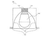
上記実施の形態1、2で示した照明ランプ100乃至100dは、この照明ランプの口金部に嵌合するソケット及び1つあるいは複数の照明ランプを収容する筐体と組み合わされて、照明装置を構成することができる。図7は、実施の形態1、2に係る照明ランプ100〜100dが適用された照明装置150の構成を示す断面図である。なお、図7では、実施の形態1に係る照明ランプ100bが適用された場合を例に示している。
The
図7に示すように、照明装置150は、照明ランプ100bを内包する器具本体170と、照明ランプ100bの口金部4b(図示省略)が取り付けられるソケット160と、器具本体170内に設けられ照明ランプ100から出射される光を反射するリフレクタ180とを備える。
図7に例示する照明装置150は、天井190に形成された開口部に挿入され、天井190側から室内を照明する照明装置である。このような天井取り付け型の照明装置のほか、たとえば、壁に設置される照明装置、卓上に載置される照明装置などに、実施の形態1、2で示した他の照明ランプを適用することができる。
As shown in FIG. 7, the
The
1 光源、2 グローブ、2a グローブ、3 筐体、3a 筐体、3c 筐体、3d 筐体、4 口金部、4b 口金部、4c 口金部、4d 口金部、5 点灯回路、6 起毛部、6a 起毛部、6c 起毛部、6d 起毛部、9 ネジ、10 LED、11 LED基板、30 第1の筐体部、30a 第1の筐体部、30c 第1の筐体部、30d 第1の筐体部、31 第2の筐体部、31a 第2の筐体部、31b 第2筐体部、31c 第2の筐体部、31d 第2の筐体部、90 開口部、100 照明ランプ、100a 照明ランプ、100b 照明ランプ、100c 照明ランプ、100d 照明ランプ、150 照明装置、160 ソケット、170 器具本体、180 リフレクタ、190 天井、300 内側面、301 外側面、301c 外側面、302c 内側面、303 第1ボス部、304 第2ボス部、305c 第1のフィン部、305d 第1のフィン部、306 筒部、306c 筒部、306d 筒部、307c 外側面、307d 外側面、313 内側面、313c 内側面、314 外側面、314b 外側面、314c 外側面、315 第2のフィン部、315c 第2のフィン部、315d 第2のフィン部、316 筒部、316c 筒部、316d 筒部、317 取付面部、317c 取付面部、318 外側面、318a 外側面、318c 外側面、318d 外側面、500 回路基板、501 回路部品、700 開口、701 開口、702 開口。 DESCRIPTION OF SYMBOLS 1 Light source, 2 globe, 2a globe, 3 housing | casing, 3a housing | casing, 3c housing | casing, 3d housing | casing, 4 base part, 4b base part, 4c base part, 4d base part, 5 lighting circuit, 6 raising part, 6a Brushed part, 6c Brushed part, 6d Brushed part, 9 Screw, 10 LED, 11 LED board, 30 1st housing | casing part, 30a 1st housing | casing part, 30c 1st housing | casing part, 30d 1st housing | casing Body part, 31 second housing part, 31a second housing part, 31b second housing part, 31c second housing part, 31d second housing part, 90 opening part, 100 illumination lamp, 100a illumination lamp, 100b illumination lamp, 100c illumination lamp, 100d illumination lamp, 150 illumination device, 160 socket, 170 instrument body, 180 reflector, 190 ceiling, 300 inner surface, 301 outer surface, 301c Side, 302c Inner side, 303 First boss, 304 Second boss, 305c First fin, 305d First fin, 306 Tube, 306c Tube, 306d Tube, 307c Outside, 307d Outside Side surface, 313 Inner side surface, 313c Inner side surface, 314 Outer side surface, 314b Outer side surface, 314c Outer side surface, 315 Second fin portion, 315c Second fin portion, 315d Second fin portion, 316 Tube portion, 316c Tube portion 316d cylinder portion, 317 mounting surface portion, 317c mounting surface portion, 318 outer side surface, 318a outer side surface, 318c outer side surface, 318d outer side surface, 500 circuit board, 501 circuit component, 700 opening, 701 opening, 702 opening.
Claims (9)
前記筐体の一端側に接続される口金部と、
前記筐体の他端側に設けられる光源と、
前記筐体に収容され、前記口金部を経由して供給される商用電力を前記光源の駆動に利用される駆動電力に変換して前記光源に供給する点灯回路と、
前記筐体の外側に設けられ、前記筐体の外周面積よりも面積が小さい握持部材と、
を備えた
ことを特徴とする照明ランプ。 A cylindrical housing;
A base connected to one end of the housing;
A light source provided on the other end of the housing;
A lighting circuit that is housed in the housing and converts the commercial power supplied via the base part into drive power used to drive the light source and supplies the light source;
A gripping member provided on the outside of the housing, having a smaller area than the outer peripheral area of the housing;
An illumination lamp characterized by comprising:
起毛した繊維が形成されている
ことを特徴とする請求項1に記載の照明ランプ。 The gripping member is
The raised lamp according to claim 1, wherein a raised fiber is formed.
外周面から突出している複数のフィン部を有し、
前記フィン部は、
前記筐体の前記一端側から前記他端側にかけて形成され、
前記握持部材は、
少なくとも前記フィン部の外側面に設けられている
ことを特徴とする請求項1又は2に記載の照明ランプ。 The housing is
Having a plurality of fin portions protruding from the outer peripheral surface;
The fin portion is
Formed from the one end side of the housing to the other end side,
The gripping member is
The illumination lamp according to claim 1, wherein the illumination lamp is provided at least on an outer surface of the fin portion.
一端側が前記口金部に接続され、樹脂で構成された第1の筐体と、
一端側が前記第1の筐体の他端側に接続され、他端側に前記光源が設けられ、金属で構成された第2の筐体とを有し、
前記第1の筐体は、
外周面から突出している複数の第1のフィン部が形成され、
前記第2の筐体は、
外周面から突出している複数の第2のフィン部が形成されている
ことを特徴とする請求項3に記載の照明ランプ。 The housing is
One end side is connected to the base part, a first housing made of resin,
One end side is connected to the other end side of the first casing, the light source is provided on the other end side, and has a second casing made of metal,
The first housing is
A plurality of first fin portions protruding from the outer peripheral surface are formed,
The second housing is
The illumination lamp according to claim 3, wherein a plurality of second fin portions projecting from the outer peripheral surface are formed.
ことを特徴とする請求項4に記載の照明ランプ。 The illumination according to claim 4, wherein the first fin portion is formed so as to protrude from the center of the diameter of the housing to be larger than the second fin portion. lamp.
ことを特徴とする請求項4又は5に記載の照明ランプ。 The illumination lamp according to claim 4 or 5, wherein the gripping member is provided on at least one of the first fin portion and the second fin portion.
前記第1のフィン部及び前記第2のフィン部が、前記筐体の外側面の周方向に交互に設けられている
ことを特徴とする請求項4〜6のいずれか一項に記載の照明ランプ。 In the case,
The illumination according to any one of claims 4 to 6, wherein the first fin portion and the second fin portion are alternately provided in a circumferential direction of the outer surface of the housing. lamp.
ことを特徴とする請求項1〜7のいずれか一項に記載の照明ランプ。 The illumination lamp according to any one of claims 1 to 7, wherein the light source is an LED, a laser diode, or an organic EL.
ことを特徴とする照明装置。 An illumination device comprising the illumination lamp according to any one of claims 1 to 8.
Priority Applications (1)
| Application Number | Priority Date | Filing Date | Title |
|---|---|---|---|
| JP2013141565A JP2015015170A (en) | 2013-07-05 | 2013-07-05 | Illumination lamp and lighting device including the same |
Applications Claiming Priority (1)
| Application Number | Priority Date | Filing Date | Title |
|---|---|---|---|
| JP2013141565A JP2015015170A (en) | 2013-07-05 | 2013-07-05 | Illumination lamp and lighting device including the same |
Publications (2)
| Publication Number | Publication Date |
|---|---|
| JP2015015170A true JP2015015170A (en) | 2015-01-22 |
| JP2015015170A5 JP2015015170A5 (en) | 2016-08-04 |
Family
ID=52436768
Family Applications (1)
| Application Number | Title | Priority Date | Filing Date |
|---|---|---|---|
| JP2013141565A Pending JP2015015170A (en) | 2013-07-05 | 2013-07-05 | Illumination lamp and lighting device including the same |
Country Status (1)
| Country | Link |
|---|---|
| JP (1) | JP2015015170A (en) |
Citations (7)
| Publication number | Priority date | Publication date | Assignee | Title |
|---|---|---|---|---|
| JP3047809U (en) * | 1997-10-07 | 1998-04-28 | 光信電気工業株式会社 | Industrial lamp |
| JP2001296033A (en) * | 2000-04-13 | 2001-10-26 | Hitachi Hometec Ltd | Ceiling radiation heater |
| JP2002173861A (en) * | 2000-12-05 | 2002-06-21 | Toray Ind Inc | Fiber molded article and method of manufacturing the same |
| JP2003208801A (en) * | 2001-11-06 | 2003-07-25 | Hitachi Ltd | Light source for projector and projection type image display device using it |
| JP2011204444A (en) * | 2010-03-25 | 2011-10-13 | Toshiba Lighting & Technology Corp | Light emitting device and lighting equipment |
| JP2012517659A (en) * | 2009-02-09 | 2012-08-02 | オスラム アクチエンゲゼルシャフト | Cooling body for lighting device |
| JP2013055034A (en) * | 2011-06-29 | 2013-03-21 | Rohm Co Ltd | Led lightbulb |
-
2013
- 2013-07-05 JP JP2013141565A patent/JP2015015170A/en active Pending
Patent Citations (7)
| Publication number | Priority date | Publication date | Assignee | Title |
|---|---|---|---|---|
| JP3047809U (en) * | 1997-10-07 | 1998-04-28 | 光信電気工業株式会社 | Industrial lamp |
| JP2001296033A (en) * | 2000-04-13 | 2001-10-26 | Hitachi Hometec Ltd | Ceiling radiation heater |
| JP2002173861A (en) * | 2000-12-05 | 2002-06-21 | Toray Ind Inc | Fiber molded article and method of manufacturing the same |
| JP2003208801A (en) * | 2001-11-06 | 2003-07-25 | Hitachi Ltd | Light source for projector and projection type image display device using it |
| JP2012517659A (en) * | 2009-02-09 | 2012-08-02 | オスラム アクチエンゲゼルシャフト | Cooling body for lighting device |
| JP2011204444A (en) * | 2010-03-25 | 2011-10-13 | Toshiba Lighting & Technology Corp | Light emitting device and lighting equipment |
| JP2013055034A (en) * | 2011-06-29 | 2013-03-21 | Rohm Co Ltd | Led lightbulb |
Similar Documents
| Publication | Publication Date | Title |
|---|---|---|
| JP4917697B2 (en) | Lamp and lighting device | |
| KR101227527B1 (en) | Lighting apparatus | |
| JP5218747B2 (en) | Lighting device | |
| JP5319749B2 (en) | Lighting device | |
| JP5643670B2 (en) | Luminous flux control member and lighting device | |
| JP2009117346A (en) | Illuminating device | |
| KR20110054068A (en) | Illumination device comprising a light-emitting diode | |
| JP5717114B1 (en) | Straight tube light emitting diode lighting | |
| JP2007179906A (en) | Illumination device | |
| JP2017050187A (en) | Lighting fixture | |
| WO2015019682A1 (en) | Lighting device | |
| JP2013239283A (en) | Light source device and lighting device using the same | |
| JP5819182B2 (en) | Lighting device | |
| JP2014512079A (en) | LED lamp provided with LED as light emitting means and lamp shade made of glass or plastic | |
| JP2013206752A (en) | Lighting device | |
| JP2015015170A (en) | Illumination lamp and lighting device including the same | |
| JP2019012617A (en) | Lighting device | |
| JP2015011773A (en) | Illumination lamp and luminaire including the same | |
| JP6318507B2 (en) | LIGHTING DEVICE WITH LIGHTING LAMP AND LIGHTING LAMP | |
| JP5701675B2 (en) | Cover and lighting device provided with the cover | |
| JP2013182776A (en) | Lighting device | |
| WO2017002960A1 (en) | Illumination device | |
| JP2013157488A (en) | Led lamp | |
| JP5860132B2 (en) | Cover and lighting device provided with the cover | |
| JP6081563B2 (en) | Lighting device |
Legal Events
| Date | Code | Title | Description |
|---|---|---|---|
| A521 | Request for written amendment filed |
Free format text: JAPANESE INTERMEDIATE CODE: A523 Effective date: 20160617 |
|
| A621 | Written request for application examination |
Free format text: JAPANESE INTERMEDIATE CODE: A621 Effective date: 20160617 |
|
| A977 | Report on retrieval |
Free format text: JAPANESE INTERMEDIATE CODE: A971007 Effective date: 20170309 |
|
| A131 | Notification of reasons for refusal |
Free format text: JAPANESE INTERMEDIATE CODE: A131 Effective date: 20170321 |
|
| A521 | Request for written amendment filed |
Free format text: JAPANESE INTERMEDIATE CODE: A523 Effective date: 20170522 |
|
| A131 | Notification of reasons for refusal |
Free format text: JAPANESE INTERMEDIATE CODE: A131 Effective date: 20170912 |
|
| A521 | Request for written amendment filed |
Free format text: JAPANESE INTERMEDIATE CODE: A523 Effective date: 20171106 |
|
| A02 | Decision of refusal |
Free format text: JAPANESE INTERMEDIATE CODE: A02 Effective date: 20180116 |