JP2015007353A - Rail movable device and vehicle extension system with the same - Google Patents
Rail movable device and vehicle extension system with the same Download PDFInfo
- Publication number
- JP2015007353A JP2015007353A JP2013133450A JP2013133450A JP2015007353A JP 2015007353 A JP2015007353 A JP 2015007353A JP 2013133450 A JP2013133450 A JP 2013133450A JP 2013133450 A JP2013133450 A JP 2013133450A JP 2015007353 A JP2015007353 A JP 2015007353A
- Authority
- JP
- Japan
- Prior art keywords
- rail
- rails
- pair
- movable
- receiving
- Prior art date
- Legal status (The legal status is an assumption and is not a legal conclusion. Google has not performed a legal analysis and makes no representation as to the accuracy of the status listed.)
- Pending
Links
Images


Landscapes
- Train Traffic Observation, Control, And Security (AREA)
Abstract
Description
本発明は、互いに接離可能なレールとレールの近接時における遊間を埋めるためのレール可動装置及び車両乗り入れシステムに関する。 The present invention relates to a rail movable device and a vehicle entry system for filling a gap between rails that can be brought into and out of contact with each other when the rails are close to each other.
旋回台の台上において旋回直径方向に沿ってレールを設け、当該レールに進入した鉄道車両を旋回させる転車台や、可動台の台上において可動方向に直交する方向に沿ってレールを設け、当該レールに進入した鉄道車両を平行移動させる遷車台(以下、「トラバーサ」という)、或いは、起伏回動可能な回動台の台上にレールを設けた跳ね上げ橋等は、地上に固定されたレールに対してレールを設けた可動台を可動させてレール相互間の分離と連結とを切り替え可能としている。
これらのようなレールの可動構造にあっては、レールの連結時において、レール端部同士を正確に対向させる必要がある。
このため、従来より、固定側のレールの端部の両側面から進出可能な一対のガイド部材を設け、可動台側のレール端部をガイド部材で挟み込むことでレール端部同士を正確に対向させるレール間接続装置が提案されている(例えば、特許文献1参照)。
A rail is provided along the turning diameter direction on the turntable, a turntable for turning the railway vehicle that has entered the rail, and a rail is provided along the direction perpendicular to the movable direction on the turntable, A transition platform (hereinafter referred to as “traverser”) that translates a rail vehicle that has entered the rail, or a lift bridge with a rail mounted on a platform that can be swung up and down is fixed on the ground. The movable base provided with the rail is moved relative to the rail so that the separation and connection between the rails can be switched.
In such a rail movable structure, it is necessary to make the rail ends accurately face each other when the rails are connected.
For this reason, conventionally, a pair of guide members that can be advanced from both side surfaces of the fixed rail end portion are provided, and the rail end portions on the movable base are sandwiched between the guide members so that the rail end portions are accurately opposed to each other. A rail connecting device has been proposed (see, for example, Patent Document 1).
また、上記レール間接続装置と同様に、固定側のレール端部から進出する一対のガイド部材を備え、レール内側(一対のレールが平行に並んだ状態における内側)となるガイド部材が互いに対向する双方のレールの踏面に跨がってレール同士を保持するレール間接続装置も提案されている(例えば、特許文献2参照)。 Further, similarly to the above-described inter-rail connecting device, a pair of guide members that advance from the end of the rail on the fixed side are provided, and the guide members that are on the inner side of the rail (the inner side in a state where the pair of rails are arranged in parallel) face each other. An inter-rail connection device that holds rails across the treads of both rails has also been proposed (see, for example, Patent Document 2).
ところで、上記可動台側のレールと固定側のレールとの間には、分離又は連結の際の一対のレールの相互間に干渉を生じないようにするために、相互のレール端部に遊間(隙間)が設けられている。
特許文献1のレール間接続装置の場合には、固定側のレールと可動台側のレールの相互の側面をガイド部材が保持しているが、互いのレールの踏面には遊間が生じたままの状態であるため、鉄道車両が通過する際には車体が振動して車輪とレールの衝突が繰り返され、レールとレールの継ぎ目において、変形や摩耗によって段違いや目違いが生じる原因となっていた。
By the way, in order to prevent interference between the pair of rails at the time of separation or connection between the rail on the movable base side and the rail on the fixed side, there is an idle space ( A gap) is provided.
In the case of the inter-rail connecting device of
また、特許文献2のレール間接続装置の場合には、固定側のレールと可動台側のレールの相互の踏面をガイド部材が渡った状態となるので相互の遊間が覆われるが、ガイド部材の上を鉄道車両の車輪が通過するので、ガイド部材による凹凸で車体が振動し、レールとレールの継ぎ目における変形や摩耗によって生じる段違いや目違いの発生を十分に抑えることが出来なかった。 Further, in the case of the inter-rail connecting device disclosed in Patent Document 2, the guide members cross over the treads of the fixed-side rail and the movable-side rail, so that the gap between the guide members is covered. Since the wheel of the railway vehicle passes above, the vehicle body vibrates due to the unevenness caused by the guide member, and it was not possible to sufficiently suppress the occurrence of step differences and misunderstandings caused by deformation and wear at the rail-to-rail joint.
本発明は、可動するレールの遊間の低減を図ることをその目的とする。 It is an object of the present invention to reduce the space between movable rails.
請求項1記載の発明は、
待機側の一対のレールと、
可動台側の一対のレールと、
前記可動台側の一対のレールを搭載する可動台と、
前記待機側の一対のレールと前記可動台側の一対のレールの先端部同士が分離と連結とを行うように前記可動台を可動させる可動部とを備えるレール可動装置であって、
前記待機側の一対のレール又は前記可動台側の一対のレールを、先端部に向かって踏面幅が漸次縮小する形状に形成された一対のトングレールと、これら一対のトングレールの外側側面から先端部にかけて形成されたテーパ面に摺接すると共に前記トングレールの延長方向に進出可能に支持された一対の受けレールとから構成し、
前記受けレールに進出動作を付与する駆動部と、
前記受けレールに対向する前記待機側の一対のレール又は前記可動台側の一対のレールの各レールの先端部に設けられ、前記受けレールの先端部の踏面を除く部位を挿入可能な受け入れガイド部とを有することを特徴とする。
The invention described in
A pair of rails on the standby side;
A pair of rails on the movable platform side;
A movable table on which a pair of rails on the movable table side is mounted;
A rail movable device comprising: a movable portion that moves the movable table so that the pair of rails on the standby side and the pair of rails on the movable table side are separated and connected to each other;
The pair of rails on the standby side or the pair of rails on the movable platform side are paired with a pair of tongles formed in a shape in which the tread width gradually decreases toward the tip, and the tips from the outer side surfaces of the pair of tongs rail And a pair of receiving rails that are slidably contacted with the taper surface formed over the portion and supported so as to be able to advance in the extending direction of the tongrel.
A drive unit for applying an advance operation to the receiving rail;
A receiving guide portion that is provided at the tip end of each of the pair of rails on the standby side or the pair of rails on the movable base facing the receiving rail, and that can insert a portion excluding the tread on the tip of the receiving rail. It is characterized by having.
請求項2記載の発明は、請求項1記載の発明と同様の構成を備えると共に、
前記受け入れガイド部は、その開口端が前記受けレールの先端部の端面の各部寸法よりも大きく開口し、その内部に挿入深度方向に向かって漸次縮小する部分を有することを特徴とする。
The invention according to claim 2 has the same configuration as the invention according to
The receiving guide part has an opening end that is larger than the size of each part of the end face of the front end of the receiving rail, and has a portion that gradually decreases in the insertion depth direction.
請求項3記載の発明は、請求項1又は2記載の発明と同様の構成を備えると共に、
前記可動部は前記可動台側の一対のレールに直交する方向に前記可動台の移動を行い、
前記待機側の一対のレールは前記可動台側の一対のレールの両端側にそれぞれ設けられ、
前記可動台側の一対のレールの少なくとも一端部と当該一端部に対向する前記待機側の一対のレールとの間に、前記トングレール、前記受けレール、前記駆動部及び前記受け入れガイド部を設けたことを特徴とする。
The invention according to claim 3 has the same configuration as the invention according to
The movable part moves the movable table in a direction perpendicular to the pair of rails on the movable table side,
The pair of rails on the standby side are respectively provided on both ends of the pair of rails on the movable base side,
Between the at least one end portion of the pair of rails on the movable base side and the pair of rails on the standby side facing the one end portion, the tongrel, the receiving rail, the driving portion, and the receiving guide portion are provided. It is characterized by that.
請求項4記載の発明は、請求項3記載の発明と同様の構成を備えると共に、
前記可動台側の一対のレールの両端部と当該両端部に対向するそれぞれの前記待機側の一対のレールとの間に、前記トングレール、前記受けレール、前記駆動部及び前記受け入れガイド部を設けたことを特徴とする。
The invention described in claim 4 has the same configuration as that of the invention described in claim 3,
The Tongrel, the receiving rail, the drive unit, and the receiving guide unit are provided between both ends of the pair of rails on the movable base side and the pair of rails on the standby side facing the both ends. It is characterized by that.
請求項5記載の発明は、
待機側の一対のレールと、
可動台側の一対のレールと、
前記可動台側の一対のレールを搭載する可動台と、
前記待機側の一対のレールと前記可動台側の一対のレールの先端部同士が分離と連結とを行うように前記可動台を可動させる可動部とを備えるレール可動装置であって、
前記待機側の一対のレール又は前記可動台側の一対のレールを、先端部に向かって踏面幅が漸次縮小する形状に形成された一対のトングレールと、これら一対のトングレールの外側側面から先端部にかけて形成されたテーパ面に摺接すると共に前記トングレールの延長方向に進出可能に支持された一対の受けレールとから構成し、
前記受けレールに進出動作を付与する駆動部と、
前記受けレールの先端部に設けられ、前記受けレールに対向する前記待機側の一対のレール又は前記可動台側の一対のレールの各レールの先端部の踏面を除く部位を挿入可能な受け入れガイド部とを有することを特徴とする。
The invention according to claim 5
A pair of rails on the standby side;
A pair of rails on the movable platform side;
A movable table on which a pair of rails on the movable table side is mounted;
A rail movable device comprising: a movable portion that moves the movable table so that the pair of rails on the standby side and the pair of rails on the movable table side are separated and connected to each other;
The pair of rails on the standby side or the pair of rails on the movable platform side are paired with a pair of tongles formed in a shape in which the tread width gradually decreases toward the tip, and the tips from the outer side surfaces of the pair of tongs rail And a pair of receiving rails that are slidably contacted with the taper surface formed over the portion and supported so as to be able to advance in the extending direction of the tongrel.
A drive unit for applying an advance operation to the receiving rail;
A receiving guide portion that is provided at a front end portion of the receiving rail and can be inserted into a portion of the pair of rails on the standby side or the pair of rails on the movable base side facing the receiving rail except for the tread surface of each rail. It is characterized by having.
請求項6記載の発明は、
請求項3記載のレール可動装置を備えると共に、
所定軌道の第一の線路区間と当該所定軌道よりも軌間の幅が広い特定軌道の第二の線路区間との間に設けられ、前記所定軌道を走行する連結された複数の鉄道車両が乗り入れ可能な車載レール部を備えると共に前記特定軌道を走行する貨物車両に、前記連結された複数の鉄道車両を搬入する車両乗り入れシステムであって、
前記レール可動装置の可動台は、前記第一の線路区間と前記第二の線路区間との間に設けられると共に、前記第一の線路区間と前記第二の線路区間で待ち受ける貨物車両が有する前記車載レール部とを連通する第一レール部が形成された第一の搭載面と、前記第二の線路区間に連通する第二レール部が形成された第二の搭載面とを備え、
前記第一の線路区間及び前記第二の線路区間はそれぞれ前記待機側の一対のレールを有し、
前記可動台の第一レール部は前記所定軌道と軌間の幅が等しい可動台側の一対のレールを有し
前記可動台の第二レール部は前記特定軌道と軌間の幅が等しい可動台側の一対のレールを有し、
前記第一の線路区間と前記可動台の第一レール部との間に、前記トングレール、前記受けレール、前記駆動部及び前記受け入れガイド部を設けたことを特徴とする。
The invention described in claim 6
A rail movable device according to claim 3 is provided,
It is provided between the first track section of the predetermined track and the second track section of the specific track whose width is wider than the predetermined track, and a plurality of connected railway vehicles traveling on the predetermined track can enter. A vehicle entry system that carries the plurality of connected railway vehicles to a freight vehicle that includes a vehicle-mounted rail portion and travels on the specific track,
The movable platform of the rail movable device is provided between the first track section and the second track section, and the freight vehicle waiting in the first track section and the second track section has the A first mounting surface formed with a first rail portion communicating with the in-vehicle rail portion; and a second mounting surface formed with a second rail portion communicating with the second track section;
Each of the first track section and the second track section has a pair of rails on the standby side,
The first rail portion of the movable table has a pair of rails on the movable table side having the same width between the predetermined track and the gauge, and the second rail portion of the movable table is on the movable table side having the same width between the specific track and the gauge. Having a pair of rails,
The tongrel, the receiving rail, the driving unit, and the receiving guide unit are provided between the first track section and the first rail unit of the movable base.
請求項7記載の発明は、請求項記載の発明と同様の構成を備えると共に、
前記可動台の第一レール部の前記可動台側の一対のレールに前記受け入れガイド部を設けると共に、前記第一の線路区間の前記待機側の一対のレールに前記トングレール、前記受けレール、前記駆動部を設け、
前記可動台の第二レール部の前記可動台側の一対のレールに前記トングレール、前記受けレール、前記駆動部を設けると共に、前記第二の線路区間の前記待機側の一対のレールに前記受け入れガイド部を設けたことを特徴とする。
The invention according to claim 7 has the same configuration as the invention according to claim,
The receiving guide portion is provided on the pair of rails on the movable base side of the first rail portion of the movable base, and the pair of rails on the standby side of the first track section is the Tongrel, the receiving rail, A drive unit,
The pair of rails on the movable platform side of the second rail portion of the movable platform are provided with the Tongrel, the receiving rail, and the drive unit, and the reception is performed on the pair of rails on the standby side of the second track section. A guide portion is provided.
請求項1又は5記載の発明は、待機側と可動台側のいずれか一方の一対のレールをトングレールと受けレールとから構成し、当該受けレールを対向する他方の一対のレールの先端部に向かって進出可能とする。また、受けレール又は他方の一対のレールの先端部には対向するレールの先端部を挿入可能な受け入れガイド部が設けられているので、可動台を可動させて可動台側の一対のレールを待機側の一対のレールと連結する配置とした場合に、受けレールを進出させることにより、一対のレールの先端部の相互間に発生する遊間を低減することが可能である。また、受けレールが進出すると、受け入れガイド部に対向するレールの先端部が受け入れガイド部に挿入されるので、可動台側の一対のレールの先端部と待機側の一対のレールの先端部とがズレを生じることなく同一直線上に並んだ状態を維持することが可能である。
従って、鉄道車両がレールとレールの継ぎ目を通過する際に、遊間に起因する振動による車輪とレールの衝突を回避することができ、これによるレールの変形や摩耗によって生じる段違いや目違いの発生を低減することが可能となる。
また、レールとレールの遊間をなくして相互に密接した状態とすることにより、レール相互間の電気的導通を図ることができ、レール間に電流を流す保安設備の適用が可能となり、保安性を向上させることが可能となる。
また、上記受けレールがトングレールのテーパ面に摺接しながら進出するので、当該進出の前後でレールの軌間が変化せず、車両がトングレールから受けレールにかけてレール上を安定して走行することが可能である。
また、上記レール可動装置は、汎用的な部材を用いて構成されているため、装置全体の保守が容易となるという利点を有している。
According to the first or fifth aspect of the present invention, the pair of rails on either the standby side or the movable base side is composed of a tongrel and a receiving rail, and the receiving rail is attached to the tip of the other pair of rails facing each other. It is possible to advance. Also, the receiving guide or the other pair of rails has a receiving guide portion into which the leading end portion of the opposing rail can be inserted, so that the movable base can be moved and the pair of rails on the movable base side can stand by. When the arrangement is made so as to be connected to the pair of rails on the side, it is possible to reduce the gap between the front ends of the pair of rails by advancing the receiving rail. Further, when the receiving rail advances, the tip of the rail facing the receiving guide is inserted into the receiving guide, so that the tip of the pair of rails on the movable base side and the tip of the pair of rails on the standby side are It is possible to maintain the state of being aligned on the same straight line without causing a shift.
Therefore, when a railway vehicle passes through the rail-to-rail joint, it is possible to avoid collision between the wheels and the rail due to vibration caused by play, and this can cause the occurrence of step differences and misunderstandings caused by rail deformation and wear. It becomes possible to reduce.
Also, by eliminating the gap between the rails and keeping them in close contact with each other, it is possible to achieve electrical continuity between the rails, and it is possible to apply safety equipment that allows current to flow between the rails. It becomes possible to improve.
Also, since the receiving rail advances while sliding on the tapered surface of the Tongrel, the rail gauge does not change before and after the advancement, and the vehicle can travel stably on the rail from the Tongrel to the receiving rail. Is possible.
Moreover, since the said rail movable apparatus is comprised using the general purpose member, it has the advantage that the maintenance of the whole apparatus becomes easy.
請求項2記載の発明は、受け入れガイド部の開口端が大きく開口し、その内部に挿入深度方向に向かって漸次縮小する形状部分を有するので、受けレールの先端部を容易に導き込むことが出来ると共に正確な位置に案内することが可能である。 According to the second aspect of the present invention, since the opening end of the receiving guide portion is largely open and has a shape portion that gradually decreases in the insertion depth direction, the tip end portion of the receiving rail can be easily guided. At the same time, it is possible to guide to an accurate position.
請求項3及び4記載の発明は、可動台側の一対のレールの両側に待機側の一対のレールを配置しているので、可動台側の一対のレールを用いて一方の待機側の一対のレールと他方の待機側の一対のレールとの間での車両の通行作業等を好適に行うことが可能である。
また、その際に、複数連結された車両が可動台側の一対のレールと待機側の一対のレールのつなぎ目を通過する場合でも、多くの車輪がレールと衝突することを回避することができ、これによるレールの変形や摩耗によって生じる段違いや目違いの発生を十分且つ効果的に抑制することが可能となる。
なお、トングレールと受けレールの構成は、可動台側の一対のレールと待機側の一対のレールのいずれに設けても良い。
According to the third and fourth aspects of the present invention, since the pair of rails on the standby side are arranged on both sides of the pair of rails on the movable base side, the pair of rails on the movable base side are used to form a pair of standby side rails. It is possible to suitably perform a vehicle traffic operation and the like between the rail and the other pair of standby-side rails.
Further, at that time, even when a plurality of connected vehicles pass through the joint between the pair of rails on the movable platform side and the pair of rails on the standby side, it can be avoided that many wheels collide with the rails, As a result, it is possible to sufficiently and effectively suppress the occurrence of steps and mistakes caused by rail deformation and wear.
The configuration of the tongrel and the receiving rail may be provided on either the pair of rails on the movable base side or the pair of rails on the standby side.
請求項6及び7記載の発明は、車両乗り入れシステムにおいて、請求項3記載のレール可動装置を設けているので、車両乗り入れ作業において、各の区間を走行する車両の車輪が可動台側の一対のレールと待機側の一対のレールのつなぎ目で当該各レールと衝突することを回避することができ、これによる各レールの変形や摩耗によって生じる段違いや目違いの発生を十分に抑制することが可能となる。 Since the rail movable device according to claim 3 is provided in the vehicle entry system, the wheels of the vehicle traveling in each section are arranged on the movable platform side in the vehicle entry system. It is possible to avoid collision with each rail at the joint between the rail and the pair of rails on the standby side, and it is possible to sufficiently suppress the occurrence of steps and mistakes caused by deformation and wear of each rail Become.
[実施形態の概要]
発明の実施形態として、狭軌(軌間寸法1067mmの軌道(所定軌道))を走行する鉄道列車200と、標準軌(軌間寸法1435mmの軌道(特定軌道))を走行する貨物列車100とからなる鉄道システム500において使用される車両乗り入れシステム1000について図面を参照して説明する。
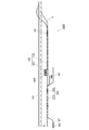
図1は車両乗り入れシステム1000を示す概略構成図である。図1に示すように、この車両乗り入れシステム1000は、狭軌の第一の線路区間Nと本線SHから分岐した標準軌の第二の線路区間Sとの間に設置されるものであって、狭軌を走行する連結された鉄道車両210を有する鉄道列車200を、凹状レール構造123(車載レール部)が形成された車体120(車両搭載部)を有する貨物列車100の貨物車両110に搬入及び搬出するためのものである。
そして、車両乗り入れシステム1000は、第一の線路区間Nと第二の線路区間Sとの間に設けられ、第一の線路区間Nと第二の線路区間Sとの境界に設けられたレール可動装置としてのトラバーサ600と、第一の線路区間Nから分岐して形成され、前記鉄道列車200の機関車201が退避する退避区間NYと、第一の線路区間Nから分岐して第一のトラバーサ600に通じる機関車戻り区間NMと、機関車201が分離した鉄道列車200を貨物列車100の貨物車両110に押し込む作業用機関車202が待機する車両格納区間NTとを備えている。
[Outline of Embodiment]
As an embodiment of the invention, a railway system comprising a
FIG. 1 is a schematic configuration diagram showing a
The
[各種の線路区間]
第一の線路区間Nは、例えば在来線の線路区間であり、狭軌の軌間幅で対を成すレールが形成されている。
本線SHは、例えば新幹線の複線の線路区間であり、標準軌の軌間幅でレールが形成されている。第二の線路区間Sは、本線SHの複線のそれぞれから分岐し、これらが合流してトラバーサ600まで形成されている。かかる第二の線路区間Sもまた、標準軌の軌間幅で対を成すレールが形成されている。
[Various track sections]
The first track section N is, for example, a conventional track section, and a pair of rails having a narrow gauge width is formed.
The main line SH is, for example, a double-track line section of a Shinkansen, and rails are formed with a standard gauge width. The second line section S branches off from each of the double lines of the main line SH, and these are merged to form the
この第二の線路区間Sのトラバーサ600の手前の部分は、鉄道列車200が乗り入れを行う際に貨物列車100が待機を行うための領域である。かかる乗り入れ作業は、貨物列車100の前側の機関車101(貨物列車100が本線SHから第二の線路区間Sに進入した場合における前側)が貨物車両110から切り離された状態で行われる。
The portion of the second track section S in front of the
退避区間NYは、第一の線路区間Nのトラバーサ600側の端部の近傍から分岐して形成されており、この退避区間NYには狭軌の軌間幅でレールが形成されている。
鉄道列車200を貨物列車100に乗り入れる際には、在来線での運行に使用されている機関車201が鉄道車両210から切り離され、当該鉄道車両210は作業用機関車202により後方からトラバーサ600に押し込まれる。機関車の交換の際には、この退避区間NYの手前で機関車201が鉄道車両210から分離され、退避区間NY内に機関車201のみが進入して退避する。
また、車両格納区間NTは、トラバーサ600の手前で機関車201の切り離しを行う鉄道列車200の後方の位置から第一の線路区間Nに合流しており、当該車両格納区間NTにも狭軌の軌間幅でレールが形成されている。
The retreat section NY is formed by branching from the vicinity of the end on the
When the
Further, the vehicle storage section NT joins the first track section N from a position behind the
機関車戻り区間NMは、退避区間NYと共に第一の線路区間Nのトラバーサ600に通じる端部の近傍から分岐している。そして、第一の線路区間Nから分岐した機関車戻り区間NMは、後述するトラバーサ600が有する位置切り替え可能な二組のレール部604,605の内の標準軌レール部605が第一の線路区間N及び第二の線路区間Sの経路上に位置合わせされている状態における狭軌レール部604に連通する位置まで形成されている。この機関車戻り区間NMには狭軌の軌間幅でレールが形成されている。
The locomotive return section NM branches off from the vicinity of the end that leads to the
[鉄道列車]
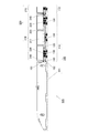
図2は鉄道システム500の側面図、図3は一部を切り欠いた正面図である。
鉄道列車200は、連結された複数の鉄道車両210と機関車201(図1参照)とから構成されている。各鉄道車両210は、ここでは一例として貨物211を積載する車両を例示している。かかる鉄道車両210は、図2及び図3に示すように、主として、貨物211が載置される車体220と、車体220の下側前端部近傍及び下側後端部近傍に設けられた台車230と、車体220の前端部と後端部のそれぞれに設けられた連結器240とから構成されている。
[Rail train]
2 is a side view of the
The
鉄道列車200の機関車201は、図2及び図3では図示しないが、正面視において鉄道車両210よりも大型であり重量もあるので、鉄道列車200から切り離され、鉄道車両210のみが貨物列車100に搭載される。
Although not shown in FIGS. 2 and 3, the
[貨物列車]
貨物列車100は、連結された複数の貨物車両110と連結された複数の貨物車両110の前端と後端とにそれぞれ接続される機関車101とから構成されている(図2は前端側のみ図示)。
かかる貨物車両110は、図2及び図3に示すように、鉄道車両210が載置される列車搭載部としての車体120と、車体120の下側前端部近傍、下側後端部近傍及び下側中間位置に設けられた三つの台車130と、車体120の前端部と後端部のそれぞれに設けられた連結器140と、各貨物車両110の間の鉄道列車200の移動を可能とする図示しない渡りレール装置と、搭載された鉄道車両210の車輪を固定する図示しない車輪保持機構とを備えている。
[freight train]
The
As shown in FIGS. 2 and 3, the
上記車体120は、台枠121と屋根及び側面をなす側構体122とからなり、内部を鉄道列車200が走行可能とするように妻構体は形成されていない。
台枠121は、その上面が平坦であり、その中央部に車体全長に渡って狭軌の幅に合わせて車載レール部としての凹状レール構造123が形成されている。
この凹状レール構造123は、台枠121の上面に対して車両進行方向の全長に渡って形成された断面矩形状の凹状部124と、平坦に形成された凹状部124の底面に固定装備された待機側の一対のレールとしてのレール体125とから構成されている。レール体125は、車体の全長に渡って形成され、その上面が鉄道車両210の車輪231の踏面に接触し、車輪231のフランジ部の外周を直接、凹状部124の底面に接触させないようになっている。かかる凹状レール構造123により、車両搭載時における鉄道列車200の走行の際に、各車輪231が凹状部124の左右の内部側面により脱輪などを生じないようにガイドされ、連結された貨物車両110の車体120上を円滑に移動することを可能としている。また、台枠121の上面に対して凹状に形成されているため、台枠121の上面にレールを設ける場合に比べて搭載時の鉄道車両210の高さを台枠121に対して低く抑えることができ、車体120の全高を低くすることを可能とし、容易に車両限界の範囲内に納めることを可能としている。
なお、台枠121の枕梁部分については、凹状レール構造123の凹状部124を形成する部材の高さを、搭載される鉄道車両210との干渉を生じない範囲でより高く形成しており、これにより強度の向上を図っている。
The
The upper surface of the
The
In addition, about the pillow beam part of the
車輪保持機構は、鉄道車両210の各車輪231の対応位置ごとに設けられ、貨物列車100の機関車101の制御の下、アクチュエーターにより各車輪231のロックと解放を行うことができる。
渡り装置は、隣接する貨物車両110と110との間に設けられ、一方の貨物車両110の左右の凹状レール構造123から他方の貨物車両110の左右の凹状レール構造123にかけわたされるレール部を備え、各車両間の鉄道列車200の走行を可能とするためのものである。具体的には、特開2008-273432号公報、特開2008-279888号公報、特開2008-307929号公報、特開2008-307931号公報に開示されている公知の渡りレール装置が搭載される。
The wheel holding mechanism is provided for each corresponding position of each
The crossing device is provided between
[貨物列車の機関車]
貨物列車100の前後の各機関車101は、牽引車両接続側の端部(貨物車両110と連結される端部)に、貨物車両110の連結器140と連結するための第一の連結器102と鉄道車両210の連結器240と連結するための第二の連結器103とを備えている。
貨物車両110と鉄道車両210はその全長が等しく、貨物車両110と同じ台数の鉄道車両210が搭載される。これにより、連結された貨物車両110と連結された鉄道車両210とはその全長が等しくなる。
また、第一の連結器102には各貨物車両110のブレーキ及び各車輪保持機構のアクチュエータの制御系を接続するための図示しない電気ジャンパ連結器が併設されており、第二の連結器103には各鉄道車両210のブレーキの制御系を接続するための図示しないエアーホースが併設されている。
[Freight train locomotive]
Each locomotive 101 before and after the
The
In addition, the
[トラバーサ]
レール可動装置としてのトラバーサ600について図4〜6により説明を行う。
トラバーサ600は、貨物列車100に対する鉄道列車200の乗り入れのために、貨物列車100の機関車101を回避して第一の線路区間Nから貨物車両110への鉄道列車200の通行を適宜可能とする。
そして、トラバーサ600は、第一と第二の搭載面602,603を有する可動台としての可動ステージ601を備えており、第一の搭載面602には狭軌幅で形成された可動台側の一対のレールである狭軌レール部604が設けられ、第二の搭載面603には標準軌幅で形成された可動台側の一対のレールである標準軌レール部605が設けられている。
[Traverser]
A
The
The
前述した第一と第二の線路区間N,Sは、対をなすレールの中心線がトラバーサ600を挟んで同一直線上となるように線路が形成されている。
そして、トラバーサ600のレール部604,605はいずれも、各線路区間N,Sにおけるトラバーサ600近傍のレールと平行に形成されており、第一の搭載面602と第二の搭載面603は、レールの延在方向に対して直交する方向に並んで配置されている。また、狭軌レール部604と標準軌レール部605は、それぞれ両端部の位置が一致するように形成されている。
In the first and second line sections N and S described above, the lines are formed such that the center lines of the paired rails are on the same straight line with the
The
また、鉄道列車200の乗り入れを行うために、第一の線路区間Nの線路は、第二の線路区間Sの線路に対して、貨物車両110と当該貨物車両110に搭載された鉄道車両210との高低差と等しい高低差が設けられている。即ち、第二の線路区間Sに貨物列車100が在線した場合の凹状レール構造123のレール体125の踏面と第一の線路区間Nのレールの踏面とが同一の高さとなるように高低差が設けられている。
このように、狭軌の線路と標準軌の線路とは高低差が設けられているので、これに対応するために、可動ステージ601の第一の搭載面602の狭軌レール部604を第一の線路区間Nのレールと同じ高さとし、第二の搭載面603の標準軌レール部605を第二の線路区間Sのレールと同じ高さとしている。これにより、可動ステージ601の第一の搭載面602と第二の搭載面603とは、第一の線路区間Nと第二の線路区間Sと同じ高低差が設けられている。
Further, in order to carry in the
As described above, since the narrow gauge track and the standard gauge track are provided with a height difference, in order to cope with this, the narrow
可動ステージ601は地上において各レール部604,605に直交する方向にスライド移動可能とするスライドガイド607,607により支持されており、当該スライド移動を行うための図示しない可動部としての可動装置610を備えている。
図6は可動装置610の概略構成を示している。可動装置610は、可動ステージ601の下側に設けられている。そして、図示のように、可動装置610は、駆動源となる可動用モーター611と、当該可動用モーター611からトルク入力を受ける減速機612,612と、減速機612,612により鉛直上下方向に沿った支軸回りに回動を行う回動アーム613,613と、二つの減速機612,612の間で可動用モーター611からのトルク伝達を行う伝達軸614とを備えている。
上記減速機612は、可動用モーター611からトルクを所定の減速比で出力し、可動ステージ601に車両が積載された状態でも移動動作させることが十分な出力を確保している。
回動アーム613は、各レール部604,605に直交する方向を向いた状態(図6(A)の状態)から各レール部604,605に平行な方向を向いた状態(図6(B)の状態)までの180°の範囲で回動動作を行う。
この回動アーム613の回動端部には回転可能なコロ615が装備されており、可動ステージ601の底部において各レール部604,605に平行な方向に形成されたガイド長穴616に挿入されている。これにより、回動アーム613が回動を行うと、コロ615がガイド長穴616内でその長手方向に沿って移動するので、回動アーム613の回動端部における各レール部604,605に平行な方向の変位は可動ステージ601に伝わらず、各レール部604,605に直交する方向の変位のみが可動ステージ601に付与される。これにより、可動ステージ601が可動して、第一と第二の線路区間N,Sに対する狭軌レール部604と標準軌レール部605との位置切り替えが行われるようになっている。
なお、回動アームを用いた可動装置は、上記構成に限らない。例えば、可動ステージ601側に駆動源となる可動用モーター611と回動アーム613等を設け、地上側にガイド長穴616を形成しても良い。
また、回動アーム613の回動角度範囲は、上記に限らず、より狭い範囲で回動させても良いし、360°全回転可能としても良い。
The
FIG. 6 shows a schematic configuration of the
The
The
A
In addition, the movable apparatus using a rotation arm is not restricted to the said structure. For example, a
Further, the rotation angle range of the
[トラバーサ:レール伸縮機構]
さらに、レール可動装置としてのトラバーサ600は、レール伸縮機構700を具備している。即ち、トラバーサ600の可動ステージ601はレールの延在方向に対して直交する方向に移動動作を行うため、第一と第二の線路区間N,Sのレールと可動ステージ601上のレール部604,605との間での干渉をさけるために、レール相互間における遊間の形成が不可避となっている。従って、この遊間を解消するために、レール伸縮機構700は、互いに対向するレールの一方を他方に向かって進出させることを可能としている。
[Traverser: Rail telescopic mechanism]
Further, the
以下、上記レール伸縮機構700が第一の線路区間Nの可動ステージ601側の端部に設けられている場合を一例として説明する。
図5及び図7に示すように。レール伸縮機構700は固定側の一対のレール701,701を構成する一対のトングレール702,702及び受けレール703,703と、一対の受けレール703,703に進出動作を付与する駆動部としての油圧シリンダー704,704と、油圧シリンダー704,704に圧油を供給する油圧ポンプ705,705と、可動ステージ601上の狭軌レール部604の一対のレールの先端部側にそれぞれ設けられた受け入れガイド部720,720とを備えている。
Hereinafter, the case where the rail expansion /
As shown in FIGS. The rail expansion /
図8〜図10は図7のA−A線とB−B線とC−C線に沿った断面図である。
一対のトングレール702,702は、その基端部(可動ステージ601とは逆側)が第一の線路区間Nの一対のレールを構成し、先端部側(可動ステージ601側)には当該トングレール702の外側側面から先端部にかけてテーパ面702a,702aが形成されており、その踏面幅が漸次狭くなっている。なお、トングレール702,702の内側側面は互いに平行な状態を維持している。
8 to 10 are cross-sectional views taken along lines AA, BB, and CC in FIG.
The pair of
一対の受けレール703,703は、その後端部(可動ステージ601とは逆側)の内側側面が一対のトングレール702,702のテーパ面702a,702aの外側に密接し、先端部(可動ステージ601側)はトングレール702,702の内側側面の幅と同じ幅で平行に配設されている。これらの受けレール703,703は、後述するレール支持構造により、それぞれその後端部側がトングレール702,702のテーパ面702a,702aに沿って外側にわずかに撓るように湾曲した状態で保持され、先端部側(トラバーサ600側)は一対のトングレール702,702と同じ間隔で平行な状態で保持される。
また、図8〜図10に示すように、トングレール702と受けレール703とが隣接する部分では、これらレール702,703の踏面の合計幅が通常の踏面幅とほぼ等しくなるように、トングレール702は先端に向かうにつれて踏面幅が徐々に小さくなるように頭部が形成されており、受けレール703は先端に向かうにつれて踏面幅が徐々に大きくなるように頭部が形成されている。
In the pair of receiving
Further, as shown in FIGS. 8 to 10, in a portion where the
図8〜図10に示すように、トングレール702と受けレール703は、コンクリートにより平滑に形成された路盤711の上にボルトにより固定された枕木712と、その上面にボルトで固定された鋼板からなる床板713とを介して敷設されている。
受けレール703は、その断面形状が、扁平な底部703aと底部703aから立ち上げられた立設部703bとその上に形成された頭部703cとから構成されている(図12参照)。また、トングレール702の断面形状も同様である。そして、当該頭部の上面は車輪に接する踏面となっている。
そして、トングレール702と受けレール703は、いずれもその底部の両側が一対のレール保持部材714,714により上から保持されている。各レール保持部材714,714は床板713に対してボルトにより固定されている。
また、図9及び図10に示すように、トングレール702と受けレール703とが並んでいる区間では、これらのレール702,703を両側から挟むようにして一対のレール保持部材714,714が保持している。
As shown in FIGS. 8 to 10, the
The receiving
Both the
Further, as shown in FIGS. 9 and 10, in a section where the
各レール保持部材714,714は、各レール702,703の立設部の側面に延びる支承部714a,714aを備えており、各レール702,703の幅方向の位置ズレを防止している。なお、各レール保持部材714,714の支承部714a,714aは、各レール702,703の立設部の側面に対してわずかなクリアランスを設けている。
各レール保持部材714,714は、各レール702,703の姿勢を安定的に保持しつつ、このクリアランスにより、受けレール703の進出移動を可能としている。
また、各レール保持部材714,714は、その底部に各レール702,703の長手方向に対して斜行した突条714c,714cを備えており、当該突条714c,714cは床板713の上面で同様に斜行形成された溝部713a,713aに嵌合しており、各レール保持部材714,714のレールの幅方向及び長手方向への位置ズレが抑止されている。
Each
The
Each
図11は受けレール703,703の先端部側周囲の拡大平面図である(一方の受けレール703の図示は省略)。
一対の受けレール703,703の立設部の外側側面には、側方に向かって延出されたブラケット部材715,715がボルトにより取り付けられており、その先端部には油圧シリンダー704,704のプランジャー部が連結されている。なお、この油圧シリンダー704,704はシリンダー部が路盤711に固定された支柱716,716により支持されている。
各油圧シリンダー704,704は複動式であり、油圧ポンプ705,705により受けレールを進出と後退のいずれにも可動させることができる。
各油圧ポンプ705,705は、図示しないトラバーサ600の制御装置の制御下にあり、可動ステージ601を可動させる可動用モーター611と連携して制御される。即ち、可動用モーター611の可動により可動ステージ601上の狭軌レール部604が第一の線路区間N又は機関車戻り区間NMの一対のレールに合致する位置に位置決めされてから各油圧ポンプ705,705が一対の受けレール703,703を進出させて対向するレールと先端部同士を密接させる動作制御が行われる。また、可動用モーター611の駆動により可動ステージ601の可動中には、各油圧ポンプ705,705が一対の受けレール703,703の後退状態を維持する動作制御が行われる。
FIG. 11 is an enlarged plan view of the periphery of the front end side of the receiving
Each of the
The
なお、一対の受けレール703,703は、トングレール702,702のテーパ面702a,702aとの摺接部分が外側に湾曲するが、進出時には、トングレール702の先端部よりも前側の部分は、その弾性により真直な状態に形状が戻るようになっている。後退時も同様である。
In addition, the pair of receiving
図12は図7におけるD−D線に沿った断面図である。図7及び図11に示すように、受け入れガイド部720,720は、狭軌レール部604の一対のレールの先端部の前側(受けレール703,703側)に設けられている。
図13は受け入れガイド部720の開口端(受けレール703側の対向面)を示す図、図14は受け入れガイド部720の平面図である。
受け入れガイド部720は、底板721と、当該底板721にボルトにより固定された左右対称形状のブロック722,723とからなり、これらが一体となった状態で、進出した受けレール703の先端部を挿入可能な開口部724が形成される。
そして、当該開口部724に挿入された受けレール703は、その底部703aの下面が底板721の上面に接し、底部703aの上面と立設部703bの側面とがブロック722,723に接して、受けレール703と狭軌レール部604のレールとが上下左右について正確に合致した状態となるようになっている。なお、受けレール703の先端面と狭軌レール部604のレールの先端面とは互いに同一形状で同一の寸法となっている。
また、この受け入れガイド部720に挿入された状態において受けレール703の頭部703cはその全体が上方に露出した状態となり、踏面を通過する車輪との干渉が生じない構造となっている。
12 is a cross-sectional view taken along line DD in FIG. As shown in FIGS. 7 and 11, the receiving
FIG. 13 is a view showing an open end of the receiving guide portion 720 (an opposing surface on the receiving
The receiving
The receiving
In addition, the
また、図13及び図14に示すように、受け入れガイド部720は受けレール703側の対向面側において、受けレール703を挿入する開口幅が上下左右について広げられている。即ち、開口部724における受けレール703の立設部703bの左右の受け入れ幅と底部703aの上下の受け入れ幅が受けレール703の各部よりも大きく広げられている。
そして、受け入れガイド部720の開口部724は、受けレール703の挿入方向の深部に向かうにつれて各部の幅が縮小し、ある程度まで挿入されると、受けレール703の各部の寸法とほぼ一致する幅となるようになっている。
受け入れガイド部720の開口部724がこのように形成されていることにより、可動ステージ601の位置決め精度の限界によって、受けレール703に対する狭軌レール部604のレールが若干の位置ズレを生じたとしても、進出する受けレール703の挿入を可能とすると共に適正な位置に導くことが可能となっている。
As shown in FIGS. 13 and 14, the receiving
The width of each part of the
Since the
なお、ここでは、レール伸縮機構700を可動ステージ601の狭軌レール部604の一対のレールと第一の線路区間Nの一対のレールとの間に設ける場合を例示したが、これに限らず、可動ステージ601の狭軌レール部604の一対のレールと機関車戻り区間NMの一対のレールとの間、可動ステージ601の狭軌レール部604の一対のレールと貨物車両110が有する凹状レール構造123との間、可動ステージ601の標準軌レール部605の一対のレールと第二の線路区間Sの一対のレールとの間にも設けても良い。
また、上記レール伸縮機構700の例では、第一の線路区間Nの一対のレールの端部を伸縮可能としたが、可動ステージ601の狭軌レール部604の一対のレールを伸縮可能としても良い。
また、可動ステージ601の狭軌レール部604の一対のレールと機関車戻り区間NMの一対のレールとの間、可動ステージ601の狭軌レール部604の一対のレールと貨物車両110が有する凹状レール構造123との間、可動ステージ601の標準軌レール部605の一対のレールと第二の線路区間Sの一対のレールとの間に伸縮機構を設ける場合も、対向するレールのいずれを伸縮可能としても良い。
また、上記各部にレール伸縮機構700と同じ構成を設けて対向するレールの遊間の発生を低減することが望ましいが、レール伸縮機構700とは異なる構成によりレールを進退させる他の構成を併用しても良い。
In addition, although the case where the rail expansion /
In the example of the rail expansion /
Also, a
In addition, it is desirable to reduce the occurrence of play between the opposing rails by providing the same configuration as the rail expansion /
[車両乗り入れ動作の説明]
図15は貨物列車100に対して鉄道列車200が乗り入れ作業を行うときの動作説明図を示している。以下、図15により乗り入れ動作の説明を行う。なお、以下の説明では、各レールの連結部においてレール伸縮機構を設けた場合を前提に説明することとする。
まず、各部のレール伸縮機構では全て受けレールが後退した状態とされ、トラバーサ600は、第二の搭載面603の標準軌レール部605が第一の線路区間Nと第二の線路区間Sのレールと同一線上となるように可動ステージ601のスライド移動が行われる。
そして、可動ステージ601の移動後に、第二の搭載面603の標準軌レール部605と第二の線路区間Sの間のレール伸縮機構は受けレールを進出させる。
かかる状態で、第二の線路区間Sから車両乗り入れシステム1000に貨物列車100が入線する(図15(A)の状態)。貨物列車100は、先頭の機関車101がトラバーサ600の第二の搭載面603上となる位置で停止し、先頭の機関車101は、貨物車両110から切り離される。
[Description of vehicle entry operation]
FIG. 15 shows an operation explanatory diagram when the
First, all the rail expansion / contraction mechanisms of the respective parts are in a state in which the receiving rail is retracted, and the
And after the movement of the
In this state, the
一方、図15に図示はしないが、第一の線路区間Nでは、鉄道列車200の機関車201が鉄道車両210から切り離されて、単独で退避区間NYに移動を行う。そして、車両格納区間NTで待機していた作業用機関車202が第一の線路区間Nに入線して鉄道車両210のみからなる鉄道列車200の後端部に連結される。
On the other hand, although not shown in FIG. 15, in the first track section N, the
次いで、第二の搭載面603の標準軌レール部605と第二の線路区間Sの間のレール伸縮機構は受けレールを後退させ、トラバーサ600は、第一の搭載面602が第一の線路区間Nと第二の線路区間Sと同一線上となるように可動ステージ601をスライド移動させる(図15(B)の状態)。そして、第一の搭載面602の狭軌レール部604と第一の線路区間Nの間のレール伸縮機構と第一の搭載面602の狭軌レール部604と貨物車両110が有する凹状レール構造123との間のレール伸縮機構は受けレールを進出させる。この状態では、切り離された各機関車101がトラバーサ600の第二の搭載面603と共に退避し、第一の搭載面602上に形成された狭軌レール部604が貨物車両110の凹状レール構造123と連通した状態となる。また、トラバーサ600の狭軌レール部604は、第一の線路区間Nのレールとも連通した状態となる。このため、作業用機関車202に後方から押された鉄道車両210が第一の線路区間Nから貨物車両110に乗り入れることができ、作業用機関車202はトラバーサ600の第一の搭載面602に搭載状態となるまで進行し、停止する。そして、作業用機関車202は鉄道車両210から切り離される。
Next, the rail telescopic mechanism between the standard
次いで、第一の搭載面602の狭軌レール部604と第一の線路区間Nの間のレール伸縮機構と第一の搭載面602の狭軌レール部604と貨物車両110が有する凹状レール構造123との間のレール伸縮機構は受けレールを後退させる。そして、トラバーサ600は、第二の搭載面603が第一の線路区間Nと第二の線路区間Sのレールと同一線上となるように可動ステージ601のスライド移動を行い、第二の搭載面603の標準軌レール部605と第二の線路区間Sの間のレール伸縮機構と第一の搭載面602の狭軌レール部604と第一の線路区間Nの間のレール伸縮機構は受けレールを進出させる。
さらに、トラバーサ600の第二の搭載面603に退避していた機関車101が再び貨物車両110の後端部に連結され、貨物列車100は第二の線路区間Sに向かって走行を開始し、車両乗り入れシステム1000から脱して、本線SHに入線する(図15(C)。
一方、トラバーサ600の第一の搭載面602に退避した作業用機関車202は、可動ステージ601の移動により、第一の搭載面602の狭軌レール部604が戻り区間NMと連通した状態となるので、作業用機関車202は戻り区間NMに移動し、第一の線路区間Nを介して、車両格納区間NTに戻される。
Next, a rail expansion / contraction mechanism between the
Furthermore, the locomotive 101 that has been retracted to the second mounting
On the other hand, the working
また、貨物列車100から鉄道車両210を搬出する際には、上記と逆の手順で行われる。
即ち、トラバーサ600は、第二の搭載面603が各区間NとSのレールと同一線上となるように可動ステージ601のスライド移動が行われ、第二の搭載面603と第二の線路区間Sとの間のレール伸縮機構が受けレールを進出させる。そして、かかる状態で第二の線路区間Sから鉄道車両210を搭載した貨物列車100がトラバーサ600の第二の搭載面603まで進入する(図15(C)参照)。
その後、先頭(トラバーサ600側)の機関車101が貨物車両110から切り離され、第二の搭載面603と第二の線路区間Sとの間のレール伸縮機構が受けレールを後退させ、トラバーサ600の第一の搭載面602が各区間NとSのレールと同一線上となるように可動ステージ601のスライド移動が行われる(図15(B)参照)。そして、第一の搭載面602の両端側のレール伸縮機構が受けレールを進出させる。
これにより、先頭の機関車101は進路から退避し、第一の線路区間Nから鉄道列車200の機関車201がトラバーサ600の第一の搭載面602に進入して鉄道車両210と連結される。そして、連結後、鉄道列車200は、第一の線路区間Nに向かって走行し、貨物車両110の上から搬出される。
そして、トラバーサ600の第一の搭載面602の両端側のレール伸縮機構が受けレールを後退させ、トラバーサ600は第二の搭載面603が各区間NとSのレールと同一線上となるように可動ステージ601のスライド移動を行う(図15(A)参照)。さらに、第二の搭載面603と第二の線路区間Sの間のレール伸縮機構は受けレールを進出させる。
その状態で、第二の搭載面603上の機関車101は貨物車両110と再び連結される。そして、連結後は、貨物列車100は、第二の線路区間Sに向かって走行を開始し、車両乗り入れシステム1000から脱して、搬出作業を完了する。
Moreover, when carrying out the
That is, in the
Thereafter, the locomotive 101 at the head (
As a result, the leading locomotive 101 retreats from the course, and the
The rail expansion / contraction mechanism on both ends of the first mounting
In this state, the locomotive 101 on the second mounting
[発明の実施形態の効果]
車両乗り入れシステム1000では、トラバーサ600の第二の搭載面603を第二の線路区間Sと通じる状態として貨物列車100の先頭の機関車101を第二の搭載面603内に格納してから、トラバーサ600の第一の搭載面602を第一の線路区間Nのレールと貨物車両110の凹状レール構造123とを連通する状態に切り換えることで、鉄道列車200を第一の線路区間Nからトラバーサ600を通過して貨物車両110の凹状レール構造123に進入することができる。従って、貨物列車100の機関車101の退避や鉄道列車200の貨物車両110への乗り入れを容易かつ迅速に行うことが可能となる。
また、トラバーサ600の第二の搭載面602を第一及び第二の線路区間N,Sと同一線上に戻すことで、分離されていた機関車101を速やかに貨物車両110に連結することが可能である。
また、逆の作業工程で、貨物列車100から鉄道列車200の搬出も可能である。
従って、これら貨物列車100に対する鉄道列車の搬入と搬出をきわめて容易且つ迅速に行うことが可能となる。
[Effect of the embodiment of the invention]
In the
Further, by returning the second mounting
Further, the
Therefore, it is possible to carry in and out the railway trains with respect to the
さらに、車両乗り入れシステム1000では、レール伸縮機構700及びその他のレール伸縮機構を備えることにより、トラバーサ600の各レール部604,605の一対のレールと各線路区間の一対のレール(さらには、貨物車両110の凹状レール構造123)との間の遊間を受けレールの進出により十分に小さくすることができ、受けレールは受け入れガイド部により正確に対向するレールと上下左右について踏面を一致させることができるので、鉄道列車200や貨物列車100がレールとレールの継ぎ目を通過する際に、振動による車輪とレールの衝突を回避することができ、これによるレールの変形や摩耗によって生じる段違いや目違いの発生を十分に抑制することが可能となる。
また、レールとレールの遊間をなくして相互に密接した状態とすることにより、レール相互間の電気的導通を図ることができ、車両乗り入れシステム1000にレール間に電流を流す保安設備の適用が可能となり、保安性を向上させることが可能となる。
Further, the
In addition, by eliminating the gap between the rails so that they are in close contact with each other, it is possible to achieve electrical continuity between the rails, and it is possible to apply safety equipment that allows current to flow between the rails in the
また、レール伸縮機構700(その他のレール伸縮機構も同様)の受け入れガイド部720の開口部724の開口端が大きく開口し、その内部に挿入深度方向に向かって漸次縮小する形状部分を有するので、受けレール703の先端部を容易に導き込むことが出来ると共に正確な位置に案内することが可能である。
In addition, since the opening end of the
特に、車両乗り入れシステム1000では、連結された鉄道列車200や貨物列車100が通過する箇所にもレール伸縮機構を配置しているので、遊間の存在により多くの車輪がレールと衝突することを回避することができ、これによるレールの変形や摩耗によって生じる段違いや目違いの発生を十分且つ効果的に抑制することが可能となる。
In particular, in the
[その他]
なお、レール伸縮機構700では、受けレール703がその長手方向の途中部分からトングレール702のテーパ面702aにより湾曲させる必要があるため、受けレール703の進出、後退時の移動距離に限界があるが、例えば、テーパ面702aによるトングレール702の先端角度をより小さくし、受けレール703の長さをより長くする等、構造上の調整により、受けレール703の進出、後退時の移動距離をより長くすることが可能である。従って、より遊間が広い場合でもレール伸縮機構700を適用することが可能である。
[Others]
In the rail expansion /
また、前述したように、レールの伸縮構造及びその進出動作を付与する構成は、地上側に限らず、トラバーサ600の可動ステージ601に搭載することも可能である。
例えば、図5の例では、第一の線路区間N、標準軌レール部605、機関車戻り区間NM側をトングレール及び受けレール等で構成し、狭軌レール部604、第二の線路区間S側に受け入れガイド部を設けた場合を例示したが、これらの中で互いに対向する組み合わせの全部又は一部について、トングレール及び受けレール等での構成と受け入れガイド部を設ける構成とを入れ替えても良い。
Further, as described above, the rail expansion / contraction structure and the configuration for providing the advancement operation thereof are not limited to the ground side, and can be mounted on the
For example, in the example of FIG. 5, the first track section N, the
また、各レール伸縮機構において、受けレールの先端部に受け入れガイド部を設け、受けレールが対向するレールに向かって前進することで、対向するレールの先端部が受けレールに設けられた受け入れガイド部に嵌合してレール間の接続が行われる構成としても良い。 Also, in each rail expansion / contraction mechanism, a receiving guide portion is provided at the front end portion of the receiving rail, and the receiving guide portion moves forward toward the facing rail so that the front end portion of the facing rail is provided on the receiving rail. It is good also as a structure by which it connects to and the connection between rails is performed.
また、可動レール装置としてレール伸縮機構700をトラバーサ600に設ける場合を例示したが、可動レール装置としてレール伸縮機構700を転車台や跳ね上げ橋に設けることも可能である。
Moreover, although the case where the rail expansion-
100 貨物列車
101 機関車
102,103 連結器
110 貨物車両
123 凹状レール構造(車載レール部)
124 凹状部
125 レール体(待機側の一対のレール)
200 鉄道列車
201 機関車
202 作業用機関車
210 鉄道車両
231 車輪
500 鉄道システム
600 トラバーサ(レール可動装置)
601 可動ステージ(可動台)
604 狭軌レール部(可動台側の一対のレール)
605 標準軌レール部(可動台側の一対のレール)
610 可動装置(可動部)
611 可動用モーター
700 レール伸縮機構
701 固定側の一対のレール(待機側の一対のレール)
702 トングレール
702a テーパ面
703 受けレール
703a 底部
703b 立設部
703c 頭部
704 油圧シリンダー(駆動部)
705 油圧ポンプ
720 ガイド部
724 開口部
1000 車両乗り入れシステム
N 第一の線路区間(待機側の一対のレール)
NM 機関車戻り区間(待機側の一対のレール)
NT 車両格納区間
S 第二の線路区間(待機側の一対のレール)
DESCRIPTION OF
124
200
601 Movable stage (movable stand)
604 Narrow gauge rail part (a pair of rails on the movable platform side)
605 Standard gauge rail (a pair of rails on the movable platform side)
610 Movable device (movable part)
611
702
705
NM locomotive return section (a pair of rails on the standby side)
NT Vehicle storage section S Second track section (a pair of rails on the standby side)
Claims (7)
可動台側の一対のレールと、
前記可動台側の一対のレールを搭載する可動台と、
前記待機側の一対のレールと前記可動台側の一対のレールの先端部同士が分離と連結とを行うように前記可動台を可動させる可動部とを備えるレール可動装置であって、
前記待機側の一対のレール又は前記可動台側の一対のレールを、先端部に向かって踏面幅が漸次縮小する形状に形成された一対のトングレールと、これら一対のトングレールの外側側面から先端部にかけて形成されたテーパ面に摺接すると共に前記トングレールの延長方向に進出可能に支持された一対の受けレールとから構成し、
前記受けレールに進出動作を付与する駆動部と、
前記受けレールに対向する前記待機側の一対のレール又は前記可動台側の一対のレールの各レールの先端部に設けられ、前記受けレールの先端部の踏面を除く部位を挿入可能な受け入れガイド部とを有することを特徴とするレール可動装置。 A pair of rails on the standby side;
A pair of rails on the movable platform side;
A movable table on which a pair of rails on the movable table side is mounted;
A rail movable device comprising: a movable portion that moves the movable table so that the pair of rails on the standby side and the pair of rails on the movable table side are separated and connected to each other;
The pair of rails on the standby side or the pair of rails on the movable platform side are paired with a pair of tongles formed in a shape in which the tread width gradually decreases toward the tip, and the tips from the outer side surfaces of the pair of tongs rail And a pair of receiving rails that are slidably contacted with the taper surface formed over the portion and supported so as to be able to advance in the extending direction of the tongrel.
A drive unit for applying an advance operation to the receiving rail;
A receiving guide portion that is provided at the tip end of each of the pair of rails on the standby side or the pair of rails on the movable base facing the receiving rail, and that can insert a portion excluding the tread on the tip of the receiving rail. The rail movable device characterized by having.
前記待機側の一対のレールは前記可動台側の一対のレールの両端側にそれぞれ設けられ、
前記可動台側の一対のレールの少なくとも一端部と当該一端部に対向する前記待機側の一対のレールとの間に、前記トングレール、前記受けレール、前記駆動部及び前記受け入れガイド部を設けたことを特徴とする請求項1又は2記載のレール可動装置。 The movable part moves the movable table in a direction perpendicular to the pair of rails on the movable table side,
The pair of rails on the standby side are respectively provided on both ends of the pair of rails on the movable base side,
Between the at least one end portion of the pair of rails on the movable base side and the pair of rails on the standby side facing the one end portion, the tongrel, the receiving rail, the driving portion, and the receiving guide portion are provided. The rail movable device according to claim 1 or 2, wherein the rail movable device is provided.
可動台側の一対のレールと、
前記可動台側の一対のレールを搭載する可動台と、
前記待機側の一対のレールと前記可動台側の一対のレールの先端部同士が分離と連結とを行うように前記可動台を可動させる可動部とを備えるレール可動装置であって、
前記待機側の一対のレール又は前記可動台側の一対のレールを、先端部に向かって踏面幅が漸次縮小する形状に形成された一対のトングレールと、これら一対のトングレールの外側側面から先端部にかけて形成されたテーパ面に摺接すると共に前記トングレールの延長方向に進出可能に支持された一対の受けレールとから構成し、
前記受けレールに進出動作を付与する駆動部と、
前記受けレールの先端部に設けられ、前記受けレールに対向する前記待機側の一対のレール又は前記可動台側の一対のレールの各レールの先端部の踏面を除く部位を挿入可能な受け入れガイド部とを有することを特徴とするレール可動装置。 A pair of rails on the standby side;
A pair of rails on the movable platform side;
A movable table on which a pair of rails on the movable table side is mounted;
A rail movable device comprising: a movable portion that moves the movable table so that the pair of rails on the standby side and the pair of rails on the movable table side are separated and connected to each other;
The pair of rails on the standby side or the pair of rails on the movable platform side are paired with a pair of tongles formed in a shape in which the tread width gradually decreases toward the tip, and the tips from the outer side surfaces of the pair of tongs rail And a pair of receiving rails that are slidably contacted with the taper surface formed over the portion and supported so as to be able to advance in the extending direction of the tongrel.
A drive unit for applying an advance operation to the receiving rail;
A receiving guide portion that is provided at a front end portion of the receiving rail and can be inserted into a portion of the pair of rails on the standby side or the pair of rails on the movable base side facing the receiving rail except for the tread surface of each rail. The rail movable device characterized by having.
所定軌道の第一の線路区間と当該所定軌道よりも軌間の幅が広い特定軌道の第二の線路区間との間に設けられ、前記所定軌道を走行する連結された複数の鉄道車両が乗り入れ可能な車載レール部を備えると共に前記特定軌道を走行する貨物車両に、前記連結された複数の鉄道車両を搬入する車両乗り入れシステムであって、
前記レール可動装置の可動台は、前記第一の線路区間と前記第二の線路区間との間に設けられると共に、前記第一の線路区間と前記第二の線路区間で待ち受ける前記貨物車両が有する前記車載レール部とを連通する第一レール部が形成された第一の搭載面と、前記第二の線路区間に連通する第二レール部が形成された第二の搭載面とを備え、
前記第一の線路区間及び前記第二の線路区間はそれぞれ前記待機側の一対のレールを有し、
前記可動台の第一レール部は前記所定軌道と軌間の幅が等しい可動台側の一対のレールを有し、
前記可動台の第二レール部は前記特定軌道と軌間の幅が等しい可動台側の一対のレールを有し、
前記第一の線路区間と前記可動台の第一レール部との間に、前記トングレール、前記受けレール、前記駆動部及び前記受け入れガイド部を設けたことを特徴とする車両乗り入れシステム。 A rail movable device according to claim 3 is provided,
It is provided between the first track section of the predetermined track and the second track section of the specific track whose width is wider than the predetermined track, and a plurality of connected railway vehicles traveling on the predetermined track can enter. A vehicle entry system that carries the plurality of connected railway vehicles to a freight vehicle that includes a vehicle-mounted rail portion and travels on the specific track,
The movable platform of the rail movable device is provided between the first track section and the second track section, and the freight vehicle waiting in the first track section and the second track section has A first mounting surface formed with a first rail portion communicating with the vehicle-mounted rail portion; and a second mounting surface formed with a second rail portion communicating with the second track section;
Each of the first track section and the second track section has a pair of rails on the standby side,
The first rail portion of the movable table has a pair of rails on the movable table side having the same width between the predetermined track and the gauge,
The second rail part of the movable table has a pair of rails on the movable table side having the same width between the specific track and the gauge,
The vehicle entry system, wherein the tongrel, the receiving rail, the driving unit, and the receiving guide unit are provided between the first track section and the first rail portion of the movable base.
前記可動台の第二レール部の前記可動台側の一対のレールに前記トングレール、前記受けレール、前記駆動部を設けると共に、前記第二の線路区間の前記待機側の一対のレールに前記受け入れガイド部を設けたことを特徴とする請求項6記載の車両乗り入れシステム。 The receiving guide portion is provided on the pair of rails on the movable base side of the first rail portion of the movable base, and the pair of rails on the standby side of the first track section is the Tongrel, the receiving rail, A drive unit,
The pair of rails on the movable platform side of the second rail portion of the movable platform are provided with the Tongrel, the receiving rail, and the drive unit, and the reception is performed on the pair of rails on the standby side of the second track section. The vehicle entry system according to claim 6, further comprising a guide portion.
Priority Applications (1)
| Application Number | Priority Date | Filing Date | Title |
|---|---|---|---|
| JP2013133450A JP2015007353A (en) | 2013-06-26 | 2013-06-26 | Rail movable device and vehicle extension system with the same |
Applications Claiming Priority (1)
| Application Number | Priority Date | Filing Date | Title |
|---|---|---|---|
| JP2013133450A JP2015007353A (en) | 2013-06-26 | 2013-06-26 | Rail movable device and vehicle extension system with the same |
Publications (1)
| Publication Number | Publication Date |
|---|---|
| JP2015007353A true JP2015007353A (en) | 2015-01-15 |
Family
ID=52337785
Family Applications (1)
| Application Number | Title | Priority Date | Filing Date |
|---|---|---|---|
| JP2013133450A Pending JP2015007353A (en) | 2013-06-26 | 2013-06-26 | Rail movable device and vehicle extension system with the same |
Country Status (1)
| Country | Link |
|---|---|
| JP (1) | JP2015007353A (en) |
Cited By (2)
| Publication number | Priority date | Publication date | Assignee | Title |
|---|---|---|---|---|
| JP2016169528A (en) * | 2015-03-12 | 2016-09-23 | 大成建設株式会社 | Traverse-angle-corresponding sleeper |
| CN111639395A (en) * | 2020-05-26 | 2020-09-08 | 成都运达科技股份有限公司 | Device and method for acquiring vehicle vibration information under transverse track expansion |
Citations (3)
| Publication number | Priority date | Publication date | Assignee | Title |
|---|---|---|---|---|
| JP2005262914A (en) * | 2004-03-16 | 2005-09-29 | Hokkaido Railway Co | Freight train and train carry-in and carry-out method |
| JP2009102011A (en) * | 2009-02-06 | 2009-05-14 | Hokkaido Railway Co | Train and railroad train carry-in/carry-out method |
| JP2012153364A (en) * | 2012-04-10 | 2012-08-16 | Hokkaido Railway Co | Railway train carrying-in/out method |
-
2013
- 2013-06-26 JP JP2013133450A patent/JP2015007353A/en active Pending
Patent Citations (3)
| Publication number | Priority date | Publication date | Assignee | Title |
|---|---|---|---|---|
| JP2005262914A (en) * | 2004-03-16 | 2005-09-29 | Hokkaido Railway Co | Freight train and train carry-in and carry-out method |
| JP2009102011A (en) * | 2009-02-06 | 2009-05-14 | Hokkaido Railway Co | Train and railroad train carry-in/carry-out method |
| JP2012153364A (en) * | 2012-04-10 | 2012-08-16 | Hokkaido Railway Co | Railway train carrying-in/out method |
Cited By (3)
| Publication number | Priority date | Publication date | Assignee | Title |
|---|---|---|---|---|
| JP2016169528A (en) * | 2015-03-12 | 2016-09-23 | 大成建設株式会社 | Traverse-angle-corresponding sleeper |
| CN111639395A (en) * | 2020-05-26 | 2020-09-08 | 成都运达科技股份有限公司 | Device and method for acquiring vehicle vibration information under transverse track expansion |
| CN111639395B (en) * | 2020-05-26 | 2023-07-04 | 成都运达科技股份有限公司 | Device and method for acquiring vibration information of vehicle under transverse track expansion |
Similar Documents
| Publication | Publication Date | Title |
|---|---|---|
| US9045150B2 (en) | Under-floor lifting jack for high-speed electric multiple unit trainset | |
| CN110877625B (en) | Ground track transfer device and track pitch transfer system | |
| JPH07309231A (en) | Track skeleton transportation device | |
| JP5234986B2 (en) | Vehicle entry system | |
| JP2015007353A (en) | Rail movable device and vehicle extension system with the same | |
| JP5808587B2 (en) | Inspection method and apparatus | |
| KR101427097B1 (en) | Fatigue testing apparatus for the gauge variable bogie | |
| JP2005262914A (en) | Freight train and train carry-in and carry-out method | |
| JP6230075B2 (en) | Rail vehicle | |
| JP5411554B2 (en) | freight train | |
| EA037425B1 (en) | Track-building carriage for receiving and/or laying track sections | |
| WO2014135852A1 (en) | Rail junction assembly | |
| JP4729628B2 (en) | Train and rail train loading / unloading method | |
| JP5260766B2 (en) | Rail train loading and unloading method | |
| JP5043873B2 (en) | Traverser, inter-rail track train moving system and railroad train loading / unloading method | |
| KR200182256Y1 (en) | Wrecking apparatus for rail-car | |
| CN207550216U (en) | A kind of TBM constructions railroad vehicle derailing resetting apparatus | |
| JP4879816B2 (en) | Heterogeneous orbit transfer device and heterogeneous orbit transfer method | |
| JP5033492B2 (en) | Cross rail device | |
| CN218143950U (en) | Relay telescopic traction device used for active traction in rail transfer platform | |
| CN111778784B (en) | Monorail and railcar system | |
| KR20140122399A (en) | Automatic track gauge conversion device | |
| CN219385826U (en) | Rail maintenance vehicle | |
| CN209815010U (en) | Automatic synchronization device for beam transporting flatcar | |
| CN103386574A (en) | Assembling device for traction device of railway vehicle |
Legal Events
| Date | Code | Title | Description |
|---|---|---|---|
| A621 | Written request for application examination |
Free format text: JAPANESE INTERMEDIATE CODE: A621 Effective date: 20160531 |
|
| A977 | Report on retrieval |
Free format text: JAPANESE INTERMEDIATE CODE: A971007 Effective date: 20170425 |
|
| A131 | Notification of reasons for refusal |
Free format text: JAPANESE INTERMEDIATE CODE: A131 Effective date: 20170509 |
|
| A02 | Decision of refusal |
Free format text: JAPANESE INTERMEDIATE CODE: A02 Effective date: 20171107 |