JP2014523297A5 - - Google Patents
Download PDFInfo
- Publication number
- JP2014523297A5 JP2014523297A5 JP2014517214A JP2014517214A JP2014523297A5 JP 2014523297 A5 JP2014523297 A5 JP 2014523297A5 JP 2014517214 A JP2014517214 A JP 2014517214A JP 2014517214 A JP2014517214 A JP 2014517214A JP 2014523297 A5 JP2014523297 A5 JP 2014523297A5
- Authority
- JP
- Japan
- Prior art keywords
- prosthetic implant
- curved
- pivot point
- implant
- bone contacting
- Prior art date
- Legal status (The legal status is an assumption and is not a legal conclusion. Google has not performed a legal analysis and makes no representation as to the accuracy of the status listed.)
- Granted
Links
- 239000007943 implant Substances 0.000 claims description 23
- 210000000988 Bone and Bones Anatomy 0.000 claims description 11
- 230000037250 Clearance Effects 0.000 description 5
- 230000035512 clearance Effects 0.000 description 5
- 210000002303 Tibia Anatomy 0.000 description 3
- 238000002513 implantation Methods 0.000 description 1
Images


Description
以下、図23〜図27を参照して、脛骨移植片112,114の共通する特徴部のいくつかの一般的な設計を移植片112の検討に基づき説明する。いくつかの実施形態では、これらの共通特徴部の構成は、実質的に同様であるが、他の実施形態では異なっていてもよいことに留意されたい。さらに、脛骨の種々の解剖学的特徴部に対する特定の移植片の協働作用を確実なものとするために、脛骨移植片112,114の他の態様が、大きく変更されてもよい。内側脛骨移植片112を例として説明すると、基部プレート116は、第1および第2のペグ126,128を備える骨対向面124と、(図26、図27に最もよく示されている)ドーム状底面130と、ドーム状面130を囲むように延在する平面逃げ131とを有することが示されている。図22を再び参照すると、脛骨の近位部分は、好ましくは、ペグ126,128、ドーム状面130、および逃げ131を受け入れるように調製されていることに留意されたい。この点に関して、脛骨は、好ましくは、孔132,146,134,148、ならびに湾曲輪郭136,150をそれぞれ備えるように調製されている。脛骨移植片112,114は、いずれもドーム状の底面を有するものとして示されているが、これらの骨対向面は、それぞれ、単純に平坦であってもよいし、または別の形態、例えば、凹面であってもよいことを理解されたい。 In the following, with reference to FIGS. 23-27, some general designs of common features of the tibial implants 112, 114 will be described based on a review of the implant 112. FIG. Note that in some embodiments, the configuration of these common features is substantially similar, but may be different in other embodiments. In addition, other aspects of the tibial implants 112, 114 may be significantly modified to ensure the cooperation of a particular implant with various anatomical features of the tibia. Taking the medial tibial graft 112 as an example, the base plate 116 includes a bone-facing surface 124 with first and second pegs 126, 128 and a dome-like shape (best shown in FIGS. 26 and 27). It is shown having a bottom surface 130 and a planar relief 131 that extends to surround the dome-shaped surface 130. Referring back to FIG. 22, it should be noted that the proximal portion of the tibia is preferably prepared to receive pegs 126, 128, domed surface 130, and relief 131. In this regard, the tibia is preferably prepared with holes 132, 146, 134, 148 and curved contours 136 , 150 , respectively . Although the tibial implants 112, 114 are both shown as having a dome-shaped bottom surface, each of these bone-facing surfaces may be simply flat, or another form, for example, It should be understood that it may be concave.
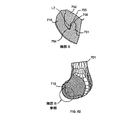
骨701への移植片710の最終的な位置付けを説明するために、多数の断面が示されている。図51を参照すると、第1の固定特徴部730を通る断面図が示されている。「細部A」の図では、干渉領域750、クリアランス領域751、および接触領域752が示されている。ここでは、クリアランス領域751は、この側面図に示されているように、後面734の中心に位置している。さらに、クリアランス領域751は、後面734の略50%を占めている。代替的実施形態では、クリアランス領域は、後面の25%から75%の範囲を占めているとよい。いずれの場合も、クリアランス領域751は、好ましくは、矢状断面に示されているように、接触領域によって取り囲まれている。干渉領域750は、前面733の実質的に中心に位置しており、図51に示されているように、接触領域によって取り囲まれている。付随して生じた力L1によって、移植片―骨界面に付勢された圧入がもたらされることになる。
A number of cross sections are shown to illustrate the final positioning of the
図64は、移植片と骨との間の幾何学的関係のバランスをさらに改良する図60〜図63に示されている脛骨移植片の断面図である。要素1020は、要素中心軸1038および内側1015の基準点1040aを有している。要素1020は、幅「d」を有しており、軸1038から基準点1040aまでの距離は、「a」である。調製された骨1001は、ペグ1020を受け入れるために調製される空洞1050を有している。空洞1050は、空洞中心軸1037を有している。骨1001は、移植片1010が完全に着座したときに点1040aと接触する基準点1040bを有している。空洞1050は、幅「d−x」を有しており、軸1037から点1040bまでの距離は、「a−y」である。移植中、ペグ1020が空洞1050内に圧入される。点1040aが点1040bに着座するとき、「a」と「a−y」との間の差および/または「d」と「d−x」との間の差によって、干渉が生じ、これによって、中心軸1038が軸1037から位置ずれするように移植片を付勢することになる。この幾何学的関係によって、図63において前述したそれぞれの干渉負荷および付随する力が生じることになる。 FIG. 64 is a cross-sectional view of the tibial graft shown in FIGS. 60-63 that further improves the balance of the geometric relationship between the graft and bone. Element 1020 has an element central axis 1038 and an inner 1015 reference point 1040a. Element 1020 has a width “d” and the distance from axis 1038 to reference point 1040a is “a”. The prepared bone 1001 has a cavity 1050 that is prepared to receive a peg 1020. The cavity 1050 has a cavity center axis 1037. Bone 1001 has a reference point 1040 b in contact with the point 1040a when the implant 1010 fully seated. The cavity 1050 has a width “d−x” and the distance from the axis 1037 to the point 1040 b is “a−y”. During implantation, the peg 1020 is pressed into the cavity 1050. When point 1040a sits at point 1040b, the difference between "a" and "ay" and / or the difference between "d" and "dx" causes interference, thereby causing The implant will be biased so that the central shaft 1038 is displaced from the shaft 1037. This geometric relationship results in the respective interference loads and associated forces previously described in FIG.
Claims (13)
第1の端(313,413,513,613,713)と、
第2の端(314,414,514,614,714)と、
関節面(22,130,222,228,311,411,511,611,711,966)と、
湾曲部を備える骨接触面(24,124,218,224,312,412,512,612,712,945)と、
前記骨接触面から延在し、第1の湾曲面を有する第1の要素(26,126,220,320,420,520,620,720)と、
前記骨接触面から延在し、第2の湾曲面を有する第2の要素(28,128,226,330,430,530,630,730)と、
を備えており、
前記第1および第2の湾曲面は、第1の旋回点(46,160,234,322,422,522,622,722,822)を中心として湾曲していることを特徴とする、補綴移植片(12,14,112,114,210,310,410,510,610,710,810,910)。 In prosthetic implants (12, 14, 112, 114, 210, 310, 410, 510, 610, 710, 810, 910),
A first end (313, 413, 513, 613, 713);
A second end (314, 414, 514, 614, 714);
Articular surfaces (22, 130, 222, 228, 311, 411, 511, 611, 711, 966);
A bone contact surface (24, 124, 218, 224, 312, 412, 512, 612, 712, 945) comprising a curved portion;
A first element (26, 126, 220, 320, 420, 520, 620, 720) extending from said bone contacting surface and having a first curved surface;
A second element (28, 128, 226, 330, 430, 530, 630, 730) extending from the bone contacting surface and having a second curved surface;
With
The first and second curved surfaces are curved around a first pivot point (46, 160, 234, 322, 422, 522, 622, 722, 822). Piece (12, 14, 112, 114, 210, 310, 410, 510, 610, 710, 810, 910).
前記第3の湾曲面は、前記第1の旋回点(46,722)を中心として湾曲していることを特徴とする、請求項1に記載の補綴移植片(12,14,112,114,210,310,410,510,610,710,810,910)。 A third element (30, 740) having a third curved surface extending from said bone contacting surface (24, 712);
The prosthetic implant (12, 14, 112, 114, 2) according to claim 1, characterized in that the third curved surface is curved around the first pivot point (46, 722). 210, 310, 410, 510, 610, 710, 810, 910).
Applications Claiming Priority (3)
| Application Number | Priority Date | Filing Date | Title |
|---|---|---|---|
| US201161500257P | 2011-06-23 | 2011-06-23 | |
| US61/500,257 | 2011-06-23 | ||
| PCT/US2012/043780 WO2012178031A1 (en) | 2011-06-23 | 2012-06-22 | Prosthetic implant and method of implantation |
Publications (3)
| Publication Number | Publication Date |
|---|---|
| JP2014523297A JP2014523297A (en) | 2014-09-11 |
| JP2014523297A5 true JP2014523297A5 (en) | 2015-05-28 |
| JP5964955B2 JP5964955B2 (en) | 2016-08-03 |
Family
ID=46457097
Family Applications (1)
| Application Number | Title | Priority Date | Filing Date |
|---|---|---|---|
| JP2014517214A Expired - Fee Related JP5964955B2 (en) | 2011-06-23 | 2012-06-22 | Prosthetic graft and method of implantation |
Country Status (6)
| Country | Link |
|---|---|
| US (2) | US9381085B2 (en) |
| EP (2) | EP2901968B1 (en) |
| JP (1) | JP5964955B2 (en) |
| AU (1) | AU2012272748C1 (en) |
| CA (1) | CA2839706C (en) |
| WO (1) | WO2012178031A1 (en) |
Families Citing this family (109)
| Publication number | Priority date | Publication date | Assignee | Title |
|---|---|---|---|---|
| US7635390B1 (en) | 2000-01-14 | 2009-12-22 | Marctec, Llc | Joint replacement component having a modular articulating surface |
| US7708741B1 (en) | 2001-08-28 | 2010-05-04 | Marctec, Llc | Method of preparing bones for knee replacement surgery |
| US9155544B2 (en) | 2002-03-20 | 2015-10-13 | P Tech, Llc | Robotic systems and methods |
| US9921712B2 (en) | 2010-12-29 | 2018-03-20 | Mako Surgical Corp. | System and method for providing substantially stable control of a surgical tool |
| US9119655B2 (en) | 2012-08-03 | 2015-09-01 | Stryker Corporation | Surgical manipulator capable of controlling a surgical instrument in multiple modes |
| US8728167B2 (en) | 2011-01-10 | 2014-05-20 | Howmedica Osteonics Corp. | Bicruciate retaining tibial baseplate design and method of implantation |
| US11771442B2 (en) | 2011-05-13 | 2023-10-03 | Biomet Manufacturing Llc | Bi-cruciate knee system |
| JP6078052B2 (en) | 2011-05-13 | 2017-02-08 | バイオメット・マニュファクチャリング,エルエルシー | Bilateral knee device (BI-CRUCIATEKNEESYSTEM) |
| MX342475B (en) * | 2011-09-29 | 2016-09-30 | Christiaan Rudolf Oosthuizen | A tibial component. |
| US8911501B2 (en) | 2011-12-29 | 2014-12-16 | Mako Surgical Corp. | Cruciate-retaining tibial prosthesis |
| FR2992164A1 (en) * | 2012-06-20 | 2013-12-27 | Tornier Sa | SET OF FEMALE IMPLANTS FOR KNEE PROSTHESIS |
| US9820818B2 (en) | 2012-08-03 | 2017-11-21 | Stryker Corporation | System and method for controlling a surgical manipulator based on implant parameters |
| US9226796B2 (en) | 2012-08-03 | 2016-01-05 | Stryker Corporation | Method for detecting a disturbance as an energy applicator of a surgical instrument traverses a cutting path |
| KR20230156801A (en) | 2012-08-03 | 2023-11-14 | 스트리커 코포레이션 | Systems and methods for robotic surgery |
| US9008757B2 (en) | 2012-09-26 | 2015-04-14 | Stryker Corporation | Navigation system including optical and non-optical sensors |
| JP6472757B2 (en) | 2013-01-16 | 2019-02-20 | ストライカー・コーポレイション | Navigation system and method for indicating and reducing line-of-sight errors |
| US9993273B2 (en) | 2013-01-16 | 2018-06-12 | Mako Surgical Corp. | Bone plate and tracking device using a bone plate for attaching to a patient's anatomy |
| US9345578B2 (en) | 2013-02-22 | 2016-05-24 | Stryker Corporation | Bicruciate retaining tibial implant system |
| US9949837B2 (en) | 2013-03-07 | 2018-04-24 | Howmedica Osteonics Corp. | Partially porous bone implant keel |
| WO2014137876A2 (en) * | 2013-03-08 | 2014-09-12 | Stryker Corporation | Bone pads |
| US20170319348A1 (en) * | 2015-08-10 | 2017-11-09 | Catalyst Orthoscience Inc. | Arthroplasty prostheses with multi-axis fixation |
| US10973646B2 (en) | 2013-03-11 | 2021-04-13 | Catalyst Orthoscience Inc. | Stabilized drill guide |
| US11007063B2 (en) | 2013-03-11 | 2021-05-18 | Catalyst Orthoscience Inc. | Offset reamers |
| EP2996611B1 (en) | 2013-03-13 | 2019-06-26 | Stryker Corporation | Systems and software for establishing virtual constraint boundaries |
| JP6442472B2 (en) | 2013-03-13 | 2018-12-19 | ストライカー・コーポレイション | System for arranging multiple objects in an operating room for a surgical procedure |
| CA2906631C (en) | 2013-03-15 | 2018-05-01 | Robert Craig COHEN | Unicondylar tibial knee implant |
| FR3007270B1 (en) * | 2013-06-19 | 2015-07-17 | Michel Bercovy | NEW PROSTHETIC FOR KNEE JOINT |
| FR3010628B1 (en) | 2013-09-18 | 2015-10-16 | Medicrea International | METHOD FOR REALIZING THE IDEAL CURVATURE OF A ROD OF A VERTEBRAL OSTEOSYNTHESIS EQUIPMENT FOR STRENGTHENING THE VERTEBRAL COLUMN OF A PATIENT |
| AU2014323515B2 (en) | 2013-09-18 | 2018-08-23 | Stryker Corporation | Patient specific bone preparation for consistent effective fixation feature engagement |
| FR3012030B1 (en) | 2013-10-18 | 2015-12-25 | Medicrea International | METHOD FOR REALIZING THE IDEAL CURVATURE OF A ROD OF A VERTEBRAL OSTEOSYNTHESIS EQUIPMENT FOR STRENGTHENING THE VERTEBRAL COLUMN OF A PATIENT |
| US9655727B2 (en) * | 2013-12-12 | 2017-05-23 | Stryker Corporation | Extended patellofemoral |
| US20150190234A1 (en) * | 2014-01-06 | 2015-07-09 | Chih-Shing Wei | Midlay compartmental tibial component |
| US9387085B2 (en) | 2014-05-30 | 2016-07-12 | Stryker Corporation | Stepped tibial baseplate |
| US9554862B2 (en) * | 2014-06-05 | 2017-01-31 | Mako Surgical Corp. | Morphologically curved sagittal wall of a tibial implant |
| WO2016138124A1 (en) | 2015-02-25 | 2016-09-01 | Mako Surgical Corp. | Navigation systems and methods for reducing tracking interruptions during a surgical procedure |
| KR102448412B1 (en) | 2015-05-19 | 2022-09-28 | 마코 서지컬 코포레이션 | Systems and Methods for Demonstrating Planned Automated Manipulation of Anatomy |
| KR102491910B1 (en) | 2015-05-19 | 2023-01-26 | 마코 서지컬 코포레이션 | Systems and methods for manipulating anatomy |
| US10117713B2 (en) | 2015-07-01 | 2018-11-06 | Mako Surgical Corp. | Robotic systems and methods for controlling a tool removing material from a workpiece |
| US10058393B2 (en) | 2015-10-21 | 2018-08-28 | P Tech, Llc | Systems and methods for navigation and visualization |
| EP3370657B1 (en) | 2015-11-04 | 2023-12-27 | Medicrea International | Apparatus for spinal reconstructive surgery and measuring spinal length |
| WO2017117369A1 (en) | 2015-12-31 | 2017-07-06 | Stryker Corporation | System and methods for performing surgery on a patient at a target site defined by a virtual object |
| US20190350726A1 (en) * | 2016-01-11 | 2019-11-21 | Kambiz Behzadi | Bone preparation apparatus and method |
| US11751807B2 (en) | 2016-01-11 | 2023-09-12 | Kambiz Behzadi | Invasive sense measurement in prosthesis installation and bone preparation |
| US11241248B2 (en) | 2016-01-11 | 2022-02-08 | Kambiz Behzadi | Bone preparation apparatus and method |
| US10245148B2 (en) | 2016-04-25 | 2019-04-02 | Howmedica Osteonics Corp. | Flexible snap-fit prosthetic component |
| US10537395B2 (en) | 2016-05-26 | 2020-01-21 | MAKO Surgical Group | Navigation tracker with kinematic connector assembly |
| US10231840B2 (en) | 2016-07-27 | 2019-03-19 | Howmedica Osteonics Corp. | Low profile tibial baseplate with fixation members |
| DE102016114059A1 (en) * | 2016-07-29 | 2018-02-01 | Aesculap Ag | Implant and joint implant |
| US10456207B2 (en) | 2016-10-21 | 2019-10-29 | Mako Surgical Corp. | Systems and tools for use with surgical robotic manipulators |
| WO2018109556A1 (en) | 2016-12-12 | 2018-06-21 | Medicrea International | Systems and methods for patient-specific spinal implants |
| US11202682B2 (en) | 2016-12-16 | 2021-12-21 | Mako Surgical Corp. | Techniques for modifying tool operation in a surgical robotic system based on comparing actual and commanded states of the tool relative to a surgical site |
| US10499997B2 (en) | 2017-01-03 | 2019-12-10 | Mako Surgical Corp. | Systems and methods for surgical navigation |
| US11406502B2 (en) | 2017-03-02 | 2022-08-09 | Optimotion Implants LLC | Orthopedic implants and methods |
| US11039938B2 (en) | 2017-07-26 | 2021-06-22 | Optimotion Implants LLC | Modular knee prothesis |
| US10905436B2 (en) | 2017-03-02 | 2021-02-02 | Optimotion Implants, Llc | Knee arthroplasty systems and methods |
| AU2018253996A1 (en) | 2017-04-21 | 2019-10-17 | Medicrea International | A system for developing one or more patient-specific spinal implants |
| EP3412251B1 (en) * | 2017-06-08 | 2021-12-15 | MAKO Surgical Corp. | Robotic bone preparation for increasing implant contact surface area |
| US10806529B2 (en) | 2017-07-20 | 2020-10-20 | Mako Surgical Corp. | System and method for robotically assisting a surgical procedure |
| AU2018316801B2 (en) | 2017-08-16 | 2023-12-21 | Mako Surgical Corp. | Ultrasound bone registration with learning-based segmentation and sound speed calibration |
| KR102018051B1 (en) * | 2017-08-29 | 2019-09-04 | 주식회사 코렌텍 | Tibia component of artificial ankle joint |
| US11027432B2 (en) | 2017-09-06 | 2021-06-08 | Stryker Corporation | Techniques for controlling position of an end effector of a robotic device relative to a virtual constraint |
| US11166775B2 (en) | 2017-09-15 | 2021-11-09 | Mako Surgical Corp. | Robotic cutting systems and methods for surgical saw blade cutting on hard tissue |
| US10893948B2 (en) | 2017-11-02 | 2021-01-19 | Howmedica Osteonics Corp. | Rotary arc patella articulating geometry |
| US11432945B2 (en) | 2017-11-07 | 2022-09-06 | Howmedica Osteonics Corp. | Robotic system for shoulder arthroplasty using stemless implant components |
| US11241285B2 (en) | 2017-11-07 | 2022-02-08 | Mako Surgical Corp. | Robotic system for shoulder arthroplasty using stemless implant components |
| US11173048B2 (en) | 2017-11-07 | 2021-11-16 | Howmedica Osteonics Corp. | Robotic system for shoulder arthroplasty using stemless implant components |
| US11272985B2 (en) | 2017-11-14 | 2022-03-15 | Stryker Corporation | Patient-specific preoperative planning simulation techniques |
| US10555781B2 (en) | 2017-11-15 | 2020-02-11 | Stryker Corporation | High bandwidth and low latency hybrid communication techniques for a navigation system |
| US10918422B2 (en) | 2017-12-01 | 2021-02-16 | Medicrea International | Method and apparatus for inhibiting proximal junctional failure |
| US11292135B2 (en) | 2018-05-31 | 2022-04-05 | Mako Surgical Corp. | Rotating switch sensor for a robotic system |
| EP3581121A1 (en) | 2018-06-15 | 2019-12-18 | MAKO Surgical Corp. | Techniques for patient-specific milling path generation |
| US10918487B2 (en) * | 2018-07-25 | 2021-02-16 | Orthopedix, Inc. | Prosthetic implant caps |
| US10925746B2 (en) * | 2018-07-25 | 2021-02-23 | Orthopedix, Inc. | Patient specific carpal implant |
| CN109009576B (en) * | 2018-08-08 | 2023-12-19 | 北京市春立正达医疗器械股份有限公司 | Unicondylar knee prosthesis |
| US11253330B2 (en) | 2018-09-26 | 2022-02-22 | Mako Surgical Corp. | Systems and tools for use with surgical robotic manipulators |
| EP3705074A1 (en) | 2019-03-08 | 2020-09-09 | MAKO Surgical Corp. | Systems and methods for controlling movement of a surgical tool along a predefined path |
| US11925417B2 (en) | 2019-04-02 | 2024-03-12 | Medicrea International | Systems, methods, and devices for developing patient-specific spinal implants, treatments, operations, and/or procedures |
| US11877801B2 (en) | 2019-04-02 | 2024-01-23 | Medicrea International | Systems, methods, and devices for developing patient-specific spinal implants, treatments, operations, and/or procedures |
| US20200345502A1 (en) * | 2019-05-02 | 2020-11-05 | DePuy Synthes Products, Inc. | Orthopaedic implant system with bone conserving features |
| AU2020359626A1 (en) | 2019-09-30 | 2022-04-14 | Mako Surgical Corp. | Systems and methods for guiding movement of a tool |
| EP4037581A1 (en) | 2019-10-01 | 2022-08-10 | Mako Surgical Corp. | Surgical systems for guiding robotic manipulators |
| US11278416B2 (en) | 2019-11-14 | 2022-03-22 | Howmedica Osteonics Corp. | Concentric keel TKA |
| US11769251B2 (en) | 2019-12-26 | 2023-09-26 | Medicrea International | Systems and methods for medical image analysis |
| EP3886056A1 (en) | 2020-03-16 | 2021-09-29 | Stryker Australia PTY LTD | Automated cut planning for removal of diseased regions |
| CN115379814A (en) | 2020-03-27 | 2022-11-22 | 马科外科公司 | System and method for controlling robot movement of a tool based on virtual boundaries |
| US20230414369A1 (en) | 2020-04-30 | 2023-12-28 | Australian Institute of Robotic Orthopaedics Pty Ltd | An orthopaedic implant and a surgical orthopaedic system incorporating same |
| KR20230049062A (en) | 2020-06-09 | 2023-04-12 | 스트리커 라이빙거 게엠바하 운트 콤파니 카게 | Spatial Awareness Displays for Computer-Aided Interventions |
| EP4188283A1 (en) * | 2020-07-30 | 2023-06-07 | Smith & Nephew, Inc. | Tibial implant with improved anterior load transfer |
| US11844697B2 (en) | 2020-09-03 | 2023-12-19 | Globus Medical, Inc. | Systems and methods for knee arthroplasty |
| US11730603B2 (en) * | 2020-09-03 | 2023-08-22 | Globus Medical, Inc. | Systems and methods for knee arthroplasty |
| EP4216859A1 (en) | 2020-09-24 | 2023-08-02 | MAKO Surgical Corp. | Interlocking collet system for a surgical device |
| AU2021269401A1 (en) * | 2020-11-25 | 2022-06-09 | Howmedica Osteonics Corp. | Fixation device for unicondylar prothesis |
| AU2021277758A1 (en) | 2020-12-30 | 2022-07-14 | Howmedica Osteonics Corp. | Cementless screw-in-peg fixation |
| CN116710017A (en) | 2020-12-31 | 2023-09-05 | 马科外科公司 | Robot system and method for mitigating undesired directional movement of a kinematic component |
| EP4291129A1 (en) | 2021-02-11 | 2023-12-20 | MAKO Surgical Corp. | Robotic manipulator comprising isolation mechanism for force/torque sensor |
| WO2022208414A1 (en) | 2021-03-31 | 2022-10-06 | Moon Surgical Sas | Co-manipulation surgical system for use with surgical instruments for performing laparoscopic surgery |
| US11832909B2 (en) | 2021-03-31 | 2023-12-05 | Moon Surgical Sas | Co-manipulation surgical system having actuatable setup joints |
| US11844583B2 (en) | 2021-03-31 | 2023-12-19 | Moon Surgical Sas | Co-manipulation surgical system having an instrument centering mode for automatic scope movements |
| US11819302B2 (en) | 2021-03-31 | 2023-11-21 | Moon Surgical Sas | Co-manipulation surgical system having user guided stage control |
| US11812938B2 (en) | 2021-03-31 | 2023-11-14 | Moon Surgical Sas | Co-manipulation surgical system having a coupling mechanism removeably attachable to surgical instruments |
| US20230013867A1 (en) | 2021-07-19 | 2023-01-19 | Mako Surgical Corp. | Surgical Tool Guard |
| AU2022328362A1 (en) | 2021-08-10 | 2024-02-22 | Mako Surgical Corp. | Tracking apparatus for tracking a patient limb |
| WO2023121966A1 (en) | 2021-12-20 | 2023-06-29 | Mako Surgical Corp. | Robotic systems, methods and software programs for modifying tool operation based on tissue parameters |
| WO2023167906A1 (en) | 2022-03-02 | 2023-09-07 | Mako Surgical Corp. | Robotic system including a link tracker |
| WO2023205072A1 (en) | 2022-04-18 | 2023-10-26 | Mako Surgical Corp. | Systems and methods for guided placement of a robotic manipulator |
| US20230390001A1 (en) | 2022-06-03 | 2023-12-07 | Mako Surgical Corp | Surgical robotic system with compliance mechanism |
| WO2024044365A1 (en) | 2022-08-26 | 2024-02-29 | Mako Surgical Corp. | Selectively automated robotic surgical system |
| WO2024054392A1 (en) | 2022-09-09 | 2024-03-14 | Mako Surgical Corp. | Robotic surgical systems for guiding a tool along a path using hybrid automated/manual control |
| US11839442B1 (en) | 2023-01-09 | 2023-12-12 | Moon Surgical Sas | Co-manipulation surgical system for use with surgical instruments for performing laparoscopic surgery while estimating hold force |
Family Cites Families (62)
| Publication number | Priority date | Publication date | Assignee | Title |
|---|---|---|---|---|
| US4085466A (en) | 1974-11-18 | 1978-04-25 | National Research Development Corporation | Prosthetic joint device |
| EP0013864B1 (en) * | 1979-01-26 | 1983-10-19 | Osteo Ag | Knee joint slide prosthesis |
| FR2466239B1 (en) * | 1979-10-03 | 1986-06-27 | Teinturier Pierre | HIP PROSTHESIS AND ITS IMPLEMENTATION |
| CA1227002A (en) | 1982-02-18 | 1987-09-22 | Robert V. Kenna | Bone prosthesis with porous coating |
| US4986833A (en) | 1989-05-05 | 1991-01-22 | Worland Richard L | Glenoid component for an artificial shoulder joint |
| US5755803A (en) | 1994-09-02 | 1998-05-26 | Hudson Surgical Design | Prosthetic implant |
| US6540786B2 (en) | 1995-08-23 | 2003-04-01 | Jean Chibrac | Joint prosthesis members and method for making same |
| US5593448A (en) * | 1995-11-14 | 1997-01-14 | Osteonics Corp. | Glenoid component for shoulder prosthesis and implant method |
| US5824100A (en) | 1996-10-30 | 1998-10-20 | Osteonics Corp. | Knee prosthesis with increased balance and reduced bearing stress |
| DE19647155C2 (en) | 1996-11-14 | 1998-11-19 | Plus Endoprothetik Ag | Implant |
| US7618451B2 (en) | 2001-05-25 | 2009-11-17 | Conformis, Inc. | Patient selectable joint arthroplasty devices and surgical tools facilitating increased accuracy, speed and simplicity in performing total and partial joint arthroplasty |
| US10085839B2 (en) * | 2004-01-05 | 2018-10-02 | Conformis, Inc. | Patient-specific and patient-engineered orthopedic implants |
| US20070100462A1 (en) * | 2001-05-25 | 2007-05-03 | Conformis, Inc | Joint Arthroplasty Devices |
| US9603711B2 (en) | 2001-05-25 | 2017-03-28 | Conformis, Inc. | Patient-adapted and improved articular implants, designs and related guide tools |
| US6723106B1 (en) | 1998-11-23 | 2004-04-20 | Microdexterity Systems, Inc. | Surgical manipulator |
| US6322567B1 (en) | 1998-12-14 | 2001-11-27 | Integrated Surgical Systems, Inc. | Bone motion tracking system |
| US8004229B2 (en) | 2005-05-19 | 2011-08-23 | Intuitive Surgical Operations, Inc. | Software center and highly configurable robotic systems for surgery and other uses |
| US6702805B1 (en) | 1999-11-12 | 2004-03-09 | Microdexterity Systems, Inc. | Manipulator |
| US6612449B1 (en) | 1999-12-10 | 2003-09-02 | Fanuc Robotics North America, Inc. | Intelligent power assisted manual manipulator |
| US6204620B1 (en) | 1999-12-10 | 2001-03-20 | Fanuc Robotics North America | Method of controlling an intelligent assist device |
| US6313595B2 (en) | 1999-12-10 | 2001-11-06 | Fanuc Robotics North America, Inc. | Method of controlling an intelligent assist device in a plurality of distinct workspaces |
| US20010034530A1 (en) | 2000-01-27 | 2001-10-25 | Malackowski Donald W. | Surgery system |
| US6712856B1 (en) * | 2000-03-17 | 2004-03-30 | Kinamed, Inc. | Custom replacement device for resurfacing a femur and method of making the same |
| US7892243B2 (en) | 2001-01-16 | 2011-02-22 | Microdexterity Systems, Inc. | Surgical manipulator |
| WO2002062199A2 (en) | 2001-01-16 | 2002-08-15 | Microdexterity Systems, Inc. | Surgical manipulator |
| WO2002060653A2 (en) | 2001-01-29 | 2002-08-08 | The Acrobot Company Limited | Active-constraint robots |
| US6482209B1 (en) | 2001-06-14 | 2002-11-19 | Gerard A. Engh | Apparatus and method for sculpting the surface of a joint |
| JP2005536703A (en) | 2001-07-05 | 2005-12-02 | マイクロデクステラティー・システムズ・インコーポレーテッド | Parallel manipulator |
| US6364910B1 (en) * | 2001-07-11 | 2002-04-02 | Biomet, Inc. | Method and apparatus for use of a glenoid component |
| US7458991B2 (en) | 2002-02-08 | 2008-12-02 | Howmedica Osteonics Corp. | Porous metallic scaffold for tissue ingrowth |
| US7831292B2 (en) | 2002-03-06 | 2010-11-09 | Mako Surgical Corp. | Guidance system and method for surgical procedures with improved feedback |
| US8010180B2 (en) | 2002-03-06 | 2011-08-30 | Mako Surgical Corp. | Haptic guidance system and method |
| US6757582B2 (en) | 2002-05-03 | 2004-06-29 | Carnegie Mellon University | Methods and systems to control a shaping tool |
| US20060147332A1 (en) | 2004-12-30 | 2006-07-06 | Howmedica Osteonics Corp. | Laser-produced porous structure |
| EP1418013B1 (en) | 2002-11-08 | 2005-01-19 | Howmedica Osteonics Corp. | Laser-produced porous surface |
| US7160330B2 (en) | 2003-01-21 | 2007-01-09 | Howmedica Osteonics Corp. | Emulating natural knee kinematics in a knee prosthesis |
| US6916341B2 (en) | 2003-02-20 | 2005-07-12 | Lindsey R. Rolston | Device and method for bicompartmental arthroplasty |
| US7387644B2 (en) * | 2003-11-07 | 2008-06-17 | University Of Vermont And State Agricultural College | Knee joint prosthesis with a femoral component which links the tibiofemoral axis of rotation with the patellofemoral axis of rotation |
| US7294149B2 (en) | 2003-12-05 | 2007-11-13 | Howmedica Osteonics Corp. | Orthopedic implant with angled pegs |
| US7544209B2 (en) | 2004-01-12 | 2009-06-09 | Lotke Paul A | Patello-femoral prosthesis |
| US7465320B1 (en) * | 2004-05-06 | 2008-12-16 | Biomet Manufacturing Corp. | Knee joint prosthesis |
| US8500843B2 (en) | 2004-07-02 | 2013-08-06 | Praxis Powder Technology, Inc. | Controlled porosity article |
| US7674426B2 (en) | 2004-07-02 | 2010-03-09 | Praxis Powder Technology, Inc. | Porous metal articles having a predetermined pore character |
| US7524334B2 (en) | 2004-11-29 | 2009-04-28 | Haidukewych George J | Tibial tray for total knee arthroplasty |
| US7766913B2 (en) | 2004-12-07 | 2010-08-03 | Depuy Products, Inc. | Bone shaping instrument and method for using the same |
| US8002777B2 (en) | 2005-06-09 | 2011-08-23 | Biomet Manufacturing Corp. | Instrumentation and method for implanting a curved stem tibial tray |
| DE102006006904A1 (en) | 2006-02-09 | 2007-08-23 | Universität Rostock | New haemostatic agents and adhesives for medical applications |
| US7628817B1 (en) | 2006-12-14 | 2009-12-08 | Howmedica Osteonics Corp. | Soft tissue deflection at a prosthetic joint |
| US7582118B2 (en) * | 2007-02-06 | 2009-09-01 | Zimmer Technology, Inc. | Femoral trochlea prostheses |
| US7950306B2 (en) | 2007-02-23 | 2011-05-31 | Microdexterity Systems, Inc. | Manipulator |
| US8366783B2 (en) | 2007-08-27 | 2013-02-05 | Samuelson Kent M | Systems and methods for providing deeper knee flexion capabilities for knee prosthesis patients |
| AU2009212243B2 (en) * | 2008-02-06 | 2014-08-07 | Exactech, Inc. | Femoral component of knee prosthesis, the femoral component having anterior/posterios claw(s) for digging into bone and/or a raised rib with a bulbous terminus |
| GB2476625B (en) | 2008-10-02 | 2013-02-13 | Mako Surgical Corp | Prosthetic device for knee joint and methods of implanting and removing same |
| AU2009314106A1 (en) | 2008-11-12 | 2010-05-20 | Howmedica Osteonics Corp., | Tetra calcium phosphate based organophosphorus compositions and methods |
| US8784490B2 (en) | 2008-11-18 | 2014-07-22 | Ray C. Wasielewski | Method of designing orthopedic implants using in vivo data |
| US8480753B2 (en) | 2009-02-27 | 2013-07-09 | Howmedica Osteonics Corp. | Spot facing trochlear groove |
| US20100268250A1 (en) | 2009-04-17 | 2010-10-21 | Microdexterity Systems, Inc. | Surgical system with medical manipulator and sterile barrier |
| US20100268249A1 (en) | 2009-04-17 | 2010-10-21 | Microdexterity Systems, Inc. | Surgical system with medical manipulator and sterile barrier |
| US20100275718A1 (en) | 2009-04-29 | 2010-11-04 | Microdexterity Systems, Inc. | Manipulator |
| CA2706233C (en) | 2009-06-04 | 2015-05-05 | Howmedica Osteonics Corp. | Orthopedic peek-on-polymer bearings |
| US9271840B2 (en) | 2010-03-10 | 2016-03-01 | John Keggi | Low stress all poly tibial component |
| US8728167B2 (en) | 2011-01-10 | 2014-05-20 | Howmedica Osteonics Corp. | Bicruciate retaining tibial baseplate design and method of implantation |
-
2012
- 2012-06-22 EP EP15158097.4A patent/EP2901968B1/en active Active
- 2012-06-22 JP JP2014517214A patent/JP5964955B2/en not_active Expired - Fee Related
- 2012-06-22 EP EP12731882.2A patent/EP2720643B1/en active Active
- 2012-06-22 AU AU2012272748A patent/AU2012272748C1/en active Active
- 2012-06-22 US US13/530,927 patent/US9381085B2/en active Active
- 2012-06-22 CA CA2839706A patent/CA2839706C/en active Active
- 2012-06-22 WO PCT/US2012/043780 patent/WO2012178031A1/en active Application Filing
-
2016
- 2016-05-24 US US15/163,146 patent/US9937058B2/en active Active
Similar Documents
| Publication | Publication Date | Title |
|---|---|---|
| JP2014523297A5 (en) | ||
| JP6077082B2 (en) | Tibial bed plate with asymmetric mounting of fixed structure | |
| AU2009270566B2 (en) | A base component for a tibial implant | |
| US7066963B2 (en) | Tibia plateau for a replacement joint | |
| JP5819068B2 (en) | Knee joint prosthesis system | |
| JP2011527220A5 (en) | ||
| WO2007016698A3 (en) | Pelvic implant systems and methods | |
| JP2011050762A (en) | Self-aligning knee prosthesis | |
| JP2012101052A (en) | Set of glenoid components for shoulder prosthesis | |
| JP2010012258A (en) | Implantable patella component having thickened superior edge | |
| JP2009523569A5 (en) | ||
| JP2013521091A (en) | Implant for joint fixation | |
| US20150272741A1 (en) | Press-fit glenoid with peripheral compression pegs | |
| JP6049380B2 (en) | Fixed bearing knee prosthesis with locking mechanism with mating interface from recess to projection | |
| CA2512617A1 (en) | A knee joint prosthesis | |
| US20150257889A1 (en) | Femoral component for a femoral knee implant system | |
| JP2017513647A5 (en) | ||
| CN103260553A (en) | Prosthetic patella | |
| US8287601B2 (en) | Femoral component of a knee prosthesis having an angled cement pocket | |
| JP2006521848A (en) | Cervical disc prosthesis | |
| US8460392B2 (en) | Knee prosthesis having cross-compatible dome and anatomic patella components | |
| FR3019032A1 (en) | FEMORAL IMPLANT COMPRISING A RECEPTION PORTION WITH ANCHORING PICOTS AND TOTAL KNEE PROSTHESIS COMPRISING SUCH A FEMORAL IMPLANT | |
| JP5844148B2 (en) | Knee prosthesis with patella components of common dimensions with various thicknesses and apex surface diameters | |
| JP2012139505A5 (en) | ||
| US20150190234A1 (en) | Midlay compartmental tibial component |