JP2014515501A - Printing periodic patterns with multiple lasers - Google Patents
Printing periodic patterns with multiple lasers Download PDFInfo
- Publication number
- JP2014515501A JP2014515501A JP2014513304A JP2014513304A JP2014515501A JP 2014515501 A JP2014515501 A JP 2014515501A JP 2014513304 A JP2014513304 A JP 2014513304A JP 2014513304 A JP2014513304 A JP 2014513304A JP 2014515501 A JP2014515501 A JP 2014515501A
- Authority
- JP
- Japan
- Prior art keywords
- mask
- light
- pattern
- irradiation
- distribution
- Prior art date
- Legal status (The legal status is an assumption and is not a legal conclusion. Google has not performed a legal analysis and makes no representation as to the accuracy of the status listed.)
- Pending
Links
Images


Classifications
-
- G—PHYSICS
- G03—PHOTOGRAPHY; CINEMATOGRAPHY; ANALOGOUS TECHNIQUES USING WAVES OTHER THAN OPTICAL WAVES; ELECTROGRAPHY; HOLOGRAPHY
- G03F—PHOTOMECHANICAL PRODUCTION OF TEXTURED OR PATTERNED SURFACES, e.g. FOR PRINTING, FOR PROCESSING OF SEMICONDUCTOR DEVICES; MATERIALS THEREFOR; ORIGINALS THEREFOR; APPARATUS SPECIALLY ADAPTED THEREFOR
- G03F7/00—Photomechanical, e.g. photolithographic, production of textured or patterned surfaces, e.g. printing surfaces; Materials therefor, e.g. comprising photoresists; Apparatus specially adapted therefor
- G03F7/70—Microphotolithographic exposure; Apparatus therefor
- G03F7/70058—Mask illumination systems
- G03F7/70075—Homogenization of illumination intensity in the mask plane by using an integrator, e.g. fly's eye lens, facet mirror or glass rod, by using a diffusing optical element or by beam deflection
-
- G—PHYSICS
- G03—PHOTOGRAPHY; CINEMATOGRAPHY; ANALOGOUS TECHNIQUES USING WAVES OTHER THAN OPTICAL WAVES; ELECTROGRAPHY; HOLOGRAPHY
- G03F—PHOTOMECHANICAL PRODUCTION OF TEXTURED OR PATTERNED SURFACES, e.g. FOR PRINTING, FOR PROCESSING OF SEMICONDUCTOR DEVICES; MATERIALS THEREFOR; ORIGINALS THEREFOR; APPARATUS SPECIALLY ADAPTED THEREFOR
- G03F7/00—Photomechanical, e.g. photolithographic, production of textured or patterned surfaces, e.g. printing surfaces; Materials therefor, e.g. comprising photoresists; Apparatus specially adapted therefor
- G03F7/70—Microphotolithographic exposure; Apparatus therefor
- G03F7/70408—Interferometric lithography; Holographic lithography; Self-imaging lithography, e.g. utilizing the Talbot effect
Abstract
本発明は、周期的なフィーチャパターン(19)を感光層(21)に印刷する方法に関する。この場合、マスクパターンを有するマスク(18)を提供するステップと、前記層を有する基板(20)を提供するステップと、マスクと平行に基板を配置するステップと、複数のピーク波長を有する複数のレーザー(1)を提供するステップと、所定の照射線量のスペクトル分布及び所定のコリメーション度でマスクを照射するビームを光から形成するステップと、マスクパターンを透過した各波長の光がタルボ平面間の所定範囲の横強度分布を形成するとともに感光層が露光されて像成分が形成されるようにビームでマスクを照射するステップとを含み、所定の波長の光で形成された所定範囲の横強度分布の平均に対して前記成分の重畳が同等となるよう離間距離及びスペクトル分布が定められ、フィーチャが解像されるようにコリメーションが定められる。 The present invention relates to a method for printing a periodic feature pattern (19) on a photosensitive layer (21). In this case, providing a mask (18) having a mask pattern, providing a substrate (20) having the layer, arranging the substrate in parallel with the mask, and a plurality of peak wavelengths. Providing a laser (1), forming a beam for irradiating the mask with a spectral distribution of a predetermined irradiation dose and a predetermined degree of collimation from the light, and light of each wavelength transmitted through the mask pattern between the Talbot planes Irradiating a mask with a beam so that the photosensitive layer is exposed to form an image component while forming a lateral intensity distribution of a predetermined range, and the lateral intensity distribution of the predetermined range formed with light of a predetermined wavelength The separation distance and the spectral distribution are determined so that the superposition of the components is equal to the average of the collimation so that the feature is resolved. ® emission is determined.
Description
本発明は一般的に、マイクロ構造やナノ構造の製作に用いられるフォトリソグラフィの分野に関し、具体的には、タルボ効果すなわち自己結像に基づくフォトリソグラフィの分野に関する。 The present invention relates generally to the field of photolithography used in the fabrication of microstructures and nanostructures, and in particular to the field of photolithography based on the Talbot effect or self-imaging.
リソグラフィ製作では、表面上にマイクロパターンやナノパターンを形成することができる。これをフォトリソグラフィ技術で実現するには、所望のパターンに対応した強度分布の光照射野に対して感光性表面を露光する。感光性表面は通常、フォトレジスト等の感光性材料の薄層であって、基板表面に直接コーティングされているか、又はその他材料の中間層上で間接的にコーティングされている。露光の結果として感光層に生じる化学的又は物理的な変化を後続のプロセスで利用することにより、基板の材料中又は別の材料の中間層中に所望のパターンが得られる。最も一般的なフォトリソグラフィ技術では、マスクに規定されたパターンの像が光学系により基板表面に投射される。このような従来のシステムで一般的に用いられているマスクは振幅マスクであって、そのパターンフィーチャは、透明基板上の不透明材料(通常、クロム)の層中における開口領域として規定されている。その他、位相シフトマスク(PSM)も用いられており、そのパターンフィーチャは、材料の一定の厚さ又は材料中の陥凹の深さによって規定されているため、このフィーチャ中を伝搬する光は他の伝搬光に対して位相がシフトする。その結果、像平面中で相互に干渉して、所望のパターンが形成される。投射式、接触式、近接式、又は従来のタルボリソグラフィで用いられるPSMの場合、マスクは、透過するすべての回折次数間の干渉を考慮して設計される。1次元パターンの場合、PSMでは、印刷可能な最小周期を振幅マスクに対して2倍小さくすることができる。これは主に、0次回折ビームを抑制することにより、1次回折ビームとの干渉による強度変調を除去することによって実現される。 In lithographic fabrication, micropatterns or nanopatterns can be formed on the surface. In order to realize this by a photolithography technique, the photosensitive surface is exposed to a light irradiation field having an intensity distribution corresponding to a desired pattern. The photosensitive surface is usually a thin layer of a photosensitive material, such as a photoresist, that is coated directly on the substrate surface or indirectly coated on an intermediate layer of other materials. By utilizing the chemical or physical changes that occur in the photosensitive layer as a result of exposure in subsequent processes, the desired pattern is obtained in the material of the substrate or in an intermediate layer of another material. In the most common photolithography technique, an image of a pattern defined on a mask is projected onto the substrate surface by an optical system. A commonly used mask in such conventional systems is an amplitude mask, whose pattern features are defined as open areas in a layer of opaque material (usually chromium) on a transparent substrate. In addition, phase shift masks (PSMs) are also used, and the pattern features are defined by a constant thickness of the material or the depth of the recess in the material, so that the light propagating in this feature is otherwise The phase shifts with respect to the propagating light. As a result, a desired pattern is formed by mutual interference in the image plane. In the case of PSMs used in projection, contact, proximity, or conventional Talbot lithography, the mask is designed taking into account the interference between all transmitted diffraction orders. In the case of a one-dimensional pattern, in the PSM, the minimum printable period can be made twice as small as the amplitude mask. This is mainly achieved by suppressing the 0th order diffracted beam and removing intensity modulation due to interference with the 1st order diffracted beam.
多くの用途において、1次元又は2次元で繰り返すパターンフィーチャの単位格子を含むパターンすなわち周期パターンが必要となる。このようなパターンをマスクから基板へ転写する特殊なフォトリソグラフィ技術は、タルボ効果に基づく。マスクに規定された周期パターンに単色光の平行ビームを照射すると、透過光照射野における回折次数によって、マスクから一定の距離ごとに存在するいわゆるタルボ平面において当該パターンの「自己像」が再構成される。これら自己像間の離間距離Sは、タルボ距離として知られるが、照射波長λ及びパターンの周期pを用いて以下のように表される。 In many applications, a pattern containing a unit cell of pattern features that repeats in one or two dimensions is required, i.e. a periodic pattern. A special photolithography technique for transferring such a pattern from the mask to the substrate is based on the Talbot effect. When a periodic pattern defined on the mask is irradiated with a parallel beam of monochromatic light, the `` self-image '' of the pattern is reconstructed on the so-called Talbot plane that exists at a certain distance from the mask due to the diffraction order in the transmitted light field. The The separation distance S between these self-images, which is known as the Talbot distance, is expressed as follows using the irradiation wavelength λ and the pattern period p.
![]()
![]()
ラインとスペースから成る1次元の周期パターンの場合はk=2であるが、2次元の周期パターンの場合、kの値は、当該パターンの配列の対称性によって決まる。この式は、p>>λの場合(すなわち、1次回折次数の角度が小さいとき)は良い精度を示すが、pの大きさがλに近づくと精度が低くなる。フォトレジストでコーティングされた基板を自己像平面のいずれかに配置すると、マスクパターンがフォトレジスト中に印刷されてしまう(たとえばC.ZankeらによるLarge area patterning for photonic crystals via coherent diffraction lithography, J.Vac.Sci.Technol.B22、3352ページ(2004年)参照)。さらに、自己像平面間の中間距離においては、マスクのパターンよりも高い空間周波数を有するタルボ副像が形成され、フォトレジストでコーティングされた基板をこれら副像平面のいずれかに置くと印刷されることになる。これらの技術により得られる印刷結果は、タルボ平面又は副像平面での強度変化が高コントラストとなるようにマスクパターンのデューティサイクル(すなわち、パターンフィーチャ周期の一部としてのフィーチャ寸法)を選択することで改善される(米国特許第4,360,586号参照)。また、従来技術においては、位相シフト材料を用いてマスクの周期パターンを製作することによりタルボ像のコントラストをさらに向上可能であることも知られている。タルボ結像を用いたフォトリソグラフィは、高解像度のパターンを印刷する従来の投射型フォトリソグラフィシステムのコストを考えると、そのような高解像度の周期パターンを印刷する場合に特に有利である。 In the case of a one-dimensional periodic pattern composed of lines and spaces, k = 2, but in the case of a two-dimensional periodic pattern, the value of k is determined by the symmetry of the arrangement of the pattern. This equation shows good accuracy when p >> λ (that is, when the angle of the first-order diffraction order is small), but the accuracy decreases as the size of p approaches λ. Placing a photoresist-coated substrate in any of the self-image planes causes a mask pattern to be printed in the photoresist (eg, Large area patterning for photonic crystals via coherent diffraction lithography, J. Vac by C. Zanke et al. Sci. Technol. B22, page 3352 (2004)). In addition, at intermediate distances between self-image planes, Talbot subimages having a higher spatial frequency than the mask pattern are formed and printed when a photoresist-coated substrate is placed on any of these subimage planes. It will be. The print results obtained by these techniques are to select the mask pattern duty cycle (ie, feature dimensions as part of the pattern feature period) so that the intensity change in the Talbot plane or sub-image plane is high contrast. (See US Pat. No. 4,360,586). In the prior art, it is also known that the contrast of the Talbot image can be further improved by producing a periodic pattern of a mask using a phase shift material. Photolithography using Talbot imaging is particularly advantageous when printing such high resolution periodic patterns, given the cost of conventional projection photolithography systems that print high resolution patterns.
ただし、タルボ技術の大きな欠点として、マスクからの距離に対する自己像及び副像の強度分布の感度が挙げられる。すなわち、被写界深度が非常に浅い。これは、パターンを正確に印刷するために、基板をマスクに対して非常に高精度に位置決めする必要があることを意味する。これは、格子周期が小さくなるにつれてより困難となる。その理由は、自己像及び副像の被写界深度がパターン周期の2乗に比例するためである。さらに、それほど平坦ではない基板表面、高レリーフの微細パターンが既に存在する表面、又はフォトレジスト厚層中へのパターンの印刷が必要な場合には、所望の結果が得られない場合もある。 However, a major drawback of the Talbot technique is the sensitivity of the intensity distribution of the self-image and the sub-image with respect to the distance from the mask. That is, the depth of field is very shallow. This means that in order to print the pattern accurately, the substrate needs to be positioned with very high precision relative to the mask. This becomes more difficult as the grating period gets smaller. The reason is that the depth of field of the self-image and the sub-image is proportional to the square of the pattern period. Furthermore, the desired result may not be obtained if printing of the pattern on a substrate surface that is not very flat, a surface that already has a high relief fine pattern, or a thick photoresist layer is required.
近年、高解像度の周期パターンを低コストで印刷する新たな方法として、収色性タルボリソグラフィ(ATL:Achromatic Talbot Lithography)が導入されている(H.H.Solakらによる"Achromatic Spatial Frequency Multiplication:A Method for Production of Nanometer-Scale Periodic Structures", J.Vac.Sci.Technol. 第23巻、2705ページ〜2710ページ(2005年)及び米国特許出願第2008/0186579号参照)。この技術は、リソグラフィへの応用として2つの有意な利点を示している。1つは、旧知のタルボ法が直面する被写界深度の問題を克服できることである。もう1つは、多くのパターン種について、空間周波数の増倍がなされることである。すなわち、マスクのパターンに対して印刷フィーチャの解像度が高くなる。ATLにおいては、光源からの広スペクトル帯域幅の平行ビームをマスクに照射すると、マスクから一定の距離を隔てて、強度分布が略不変のいわゆる静止像が透過光照射野により形成され、距離がさらに増加する。ラインとスペースから成る1次元パターン(すなわち、線形格子)の場合、静止像が生じるマスクからの最小距離dminは、マスクのパターンの周期p及びビームのスペクトルプロファイルの半値全幅Δλの関数として、以下のように表される。 In recent years, Achromatic Talbot Lithography (ATL) has been introduced as a new method for printing high-resolution periodic patterns at low cost (Achromatic Spatial Frequency Multiplication: A Method for Production by HHSolak et al.). of Nanometer-Scale Periodic Structures ", J. Vac. Sci. Technol. Vol. 23, pages 2705-2710 (2005) and US Patent Application No. 2008/0186579). This technique shows two significant advantages for lithography applications. One is to overcome the depth-of-field problem faced by the old Talbot method. Another is that spatial frequency multiplication is performed for many pattern types. That is, the resolution of the print feature is high with respect to the mask pattern. In ATL, when a parallel beam having a wide spectral bandwidth from a light source is irradiated onto a mask, a so-called still image whose intensity distribution is substantially unchanged is formed by the transmitted light irradiation field at a certain distance from the mask. To increase. In the case of a one-dimensional pattern of lines and spaces (ie, a linear grating), the minimum distance dmin from the mask at which a static image occurs is a function of the mask pattern period p and the full width at half maximum Δλ of the beam spectral profile: It is expressed as follows.
![]()
![]()
この距離を超えると、マスクからの距離の増加とともに異なる波長ごとのタルボ像平面が連続的に分布して、静止像が形成される。したがって、フォトレジストでコーティングされた基板をこの領域に置くと、特定の波長に関して連続するタルボ平面間に形成されたすべての横強度分布で基板が露光される。このため、基板上に印刷されるパターンは、この所定範囲の横強度分布の平均又は積分となって、マスクに対する基板の長手方向の変位とは実質無関係である。この技術を用いると、標準的なタルボ結像よりも被写界深度がはるかに深くなり、また、従来の投射式、近接式、又は接触式印刷と比べても被写界深度が格段に深くなる。 When this distance is exceeded, the Talbot image plane for each different wavelength is continuously distributed as the distance from the mask increases, and a still image is formed. Thus, placing a photoresist-coated substrate in this region exposes the substrate with all lateral intensity distributions formed between successive Talbot planes for a particular wavelength. For this reason, the pattern printed on the substrate is the average or integral of this predetermined range of lateral intensity distribution and is substantially independent of the displacement of the substrate in the longitudinal direction relative to the mask. With this technology, the depth of field is much deeper than standard Talbot imaging, and the depth of field is much deeper than conventional projection, proximity, or contact printing. Become.
特定のマスクパターンからのATL像における強度分布は、マスク以降の電磁波の伝搬を模擬するモデリングソフトウェアを用いて決定可能である。また、このようなシミュレーションツールを用いることにより、基板表面において特定の印刷パターンを得るためのマスクパターンの設計を最適化することも可能である。 The intensity distribution in the ATL image from a specific mask pattern can be determined using modeling software that simulates propagation of electromagnetic waves after the mask. Further, by using such a simulation tool, it is possible to optimize the design of a mask pattern for obtaining a specific print pattern on the substrate surface.
ATL法は主として、少なくとも1つの方向に一定の周期で繰り返す単位格子を含む周期パターンの印刷を目的として開発されたものである。ただし、この技術は、周期が略一定のマスクの一部によって静止像の特定部分を形成する回折次数が生成されるように、マスク全体にわたって十分に「遅く」空間的な周期が徐々に変化するパターンにも難なく適用可能である。このようなパターンは、準周期的と言い表すこともできる。 The ATL method has been developed mainly for the purpose of printing a periodic pattern including a unit cell that repeats at a constant period in at least one direction. However, this technique gradually changes the spatial period sufficiently “slow” over the entire mask so that a part of the mask with a substantially constant period produces a diffraction order that forms a specific part of the still image. It can be applied to patterns without difficulty. Such a pattern can also be described as quasi-periodic.
ATLの短所は、マスクと基板間に必要な離間距離が大きくなって不都合を被ることがないように、有意なスペクトル帯域幅の光源を要する点である。マスクから伝搬する異なる回折次数の角度発散により、基板表面における異なる次数間の空間オフセットが生じて、パターンエッジの像再構成が不完全となり、離間距離の増加とともに悪化する。また、回折次数のエッジにおけるフレネル回折によっても印刷パターンのエッジが劣化し、同じく離間距離の増加とともに悪化する。このため、レーザー光源は、スペクトル帯域幅が相対的に狭いため、ほとんどの場合においてATLには適さない。 The disadvantage of ATL is that it requires a light source with a significant spectral bandwidth so that the required separation between the mask and the substrate is not increased and incurred. The angular divergence of the different diffraction orders propagating from the mask causes spatial offsets between different orders on the substrate surface, resulting in incomplete image reconstruction of the pattern edges and worsening with increasing separation distance. Also, the edge of the printed pattern deteriorates due to Fresnel diffraction at the edge of the diffraction order, and also deteriorates as the separation distance increases. For this reason, laser light sources are not suitable for ATL in most cases due to their relatively narrow spectral bandwidth.
アーク灯や発光ダイオード等の非レーザー光源をATLに適用すると、製造プロセスにおける高スループットを確保するための高出力と高解像度のフィーチャを結像するための良好なコリメーションとの組み合わせを有する所要寸法の露光ビームを発生するのが困難となる。このような光源からのビームのコリメーションは、空間フィルタリングによって所要レベルまで向上可能であるが、一般的には許容範囲を超えるビームパワーの損失が生じる。 Application of non-laser light sources such as arc lamps and light emitting diodes to ATLs provides the required dimensions with a combination of high power to ensure high throughput in the manufacturing process and good collimation to image high resolution features. It becomes difficult to generate an exposure beam. The collimation of the beam from such a light source can be improved to a required level by spatial filtering, but generally a beam power loss exceeding an allowable range occurs.
ATL技術の利点は、米国特許出願第2008/0186579号に開示の異なる関連技術によって得られる。この方式では、マスクの周期パターンに単色光の平行ビームを照射し、当該露光中に、連続するタルボ像平面間の離間距離の整数倍に相当する範囲で基板のマスクからの距離を変化させることにより、タルボ平面間の強度分布の平均が基板上に印刷されるようにする。したがって、取り得る最小変位は、連続するタルボ平面間の離間距離に等しい(整数=1の場合)。露光中のこの変位により、基板に印刷されるパターンは、ATL技術を用いて印刷する場合と略同じである。また、範囲内の複数の離散位置において基板を露光することにより、連続的又は離散的な変位が可能となることも開示されている。この一般的な技術は、変位タルボリソグラフィ(DTL:Displacement Talbot Lithography)と称することもできる。 The advantages of ATL technology are gained by the different related technologies disclosed in US Patent Application No. 2008/0186579. In this method, the periodic pattern of the mask is irradiated with a parallel beam of monochromatic light, and during the exposure, the distance from the mask of the substrate is changed in a range corresponding to an integral multiple of the separation distance between successive Talbot image planes. Thus, the average of the intensity distribution between the Talbot planes is printed on the substrate. Thus, the smallest possible displacement is equal to the distance between successive Talbot planes (if integer = 1). Due to this displacement during exposure, the pattern printed on the substrate is substantially the same as when printing using ATL technology. It is also disclosed that continuous or discrete displacement is possible by exposing the substrate at a plurality of discrete positions within the range. This general technique can also be referred to as Displacement Talbot Lithography (DTL).
ATL技術及びDTL技術により基板で生じる平均強度分布は、本質的に同等であって、いずれも印刷パターンの被写界深度を深くできるとともに、空間周波数の増倍が可能である。DTL方式は、基板とマスク間の離間距離がATL方式よりもはるかに小さい場合に使用可能である。このため、パターンエッジの劣化が抑えられ、コリメーションに対する要求が低いことから、光源からの出力をいっそう効率的に利用可能である。さらに、DTL技術によれば、レーザー光源を使用できるようになり、製造プロセスに好適と考えられる。このような光源からの光は、パワー損失が無視できる高度にコリメートされたビームへと形成可能であることから、フィーチャ解像度の損失が最小限に抑えられる一方、像コントラストは最大化される。 The average intensity distributions generated on the substrate by the ATL technology and the DTL technology are essentially the same, and both can increase the depth of field of the printed pattern and can increase the spatial frequency. The DTL method can be used when the distance between the substrate and the mask is much smaller than that of the ATL method. For this reason, the deterioration of the pattern edge is suppressed and the demand for collimation is low, so that the output from the light source can be used more efficiently. Furthermore, according to the DTL technology, a laser light source can be used, which is considered suitable for the manufacturing process. Light from such light sources can be formed into highly collimated beams with negligible power loss, thus minimizing feature resolution loss while maximizing image contrast.
また、DTLにより特定のマスクパターンから印刷されるパターンの構造は、シミュレーションソフトウェアを用いて理論的に決定可能である。 Further, the structure of a pattern printed from a specific mask pattern by DTL can be theoretically determined using simulation software.
米国特許出願第2008/0186579号に記載のDTL技術には、露光中のマスクに対する基板の長手方向の変位をタルボ距離の整数倍と高精度に対応させる必要がある、という制約がある。変位が厳密に整数倍の場合、基板を露光する平均強度分布は、基板とマスク間の最初の離間距離とは無関係であるため、マスク及び基板が高精度に平坦かつ平行でなくても、基板上には一様なパターンフィーチャが露光される。一方、たとえば変位アクチュエータの機械的ヒステリシス又はステッピング解像度の制限もしくは照射システムによる露光継続時間と基板変位との不正確な同期により、変位がタルボ距離の厳密な整数倍でない場合、平均強度分布は、最初の離間距離によって決まる。この場合、マスク及び基板が高精度に平坦かつ平行でなければ、フィーチャサイズの空間変動が印刷パターンに取り込まれる。あるいは、マスク及び基板が高精度に平坦かつ平行ではあるものの、その離間距離が基板ごとに異なる場合は、印刷フィーチャのサイズが基板ごとに変化する。いずれの場合も、特定の用途においては問題となり得る。これらフィーチャサイズの変動は、多数のタルボ距離に相当する距離だけ基板をマスクに対して長手方向に変位させることにより抑えることができるものの、(照射ビームが高度にコリメートされていない場合の)フィーチャ解像度の劣化、(変位方向が高精度に長手方向ではない場合の)フィーチャ形状の歪み、(間隙が広すぎる場合の)パターンエッジの劣化等、別の問題を引き起こす可能性があり、機械システムの移動範囲の拡大を要するため不都合である。 The DTL technique described in US Patent Application No. 2008/0186579 has a limitation that the displacement in the longitudinal direction of the substrate with respect to the mask during exposure needs to correspond to an integral multiple of the Talbot distance with high accuracy. If the displacement is exactly an integer multiple, the average intensity distribution that exposes the substrate is independent of the initial separation distance between the substrate and the mask, so that even if the mask and substrate are not flat and parallel with high accuracy, the substrate A uniform pattern feature is exposed on top. On the other hand, if the displacement is not an exact integer multiple of the Talbot distance, for example due to mechanical hysteresis of the displacement actuator or stepping resolution limitations or inaccurate synchronization of exposure duration and substrate displacement by the illumination system, the average intensity distribution is It depends on the separation distance. In this case, if the mask and the substrate are not flat and parallel with high accuracy, the spatial variation of the feature size is taken into the print pattern. Alternatively, if the mask and the substrate are flat and parallel with high accuracy but the separation distance differs from one substrate to another, the size of the print feature changes from one substrate to another. Either case can be problematic for certain applications. These feature size variations can be suppressed by displacing the substrate longitudinally relative to the mask by a distance corresponding to many Talbot distances, but the feature resolution (when the illumination beam is not highly collimated) Movement of the mechanical system may cause other problems such as degradation of the shape, distortion of the feature shape (if the displacement direction is not precisely the longitudinal direction), degradation of the pattern edge (if the gap is too wide), etc. This is inconvenient because it requires an expanded range.
本明細書中に参考として援用する未公開米国特許出願第13/035,012号は、この制約を克服するDTL技術の改良を教示しており、露光中に基板をマスクに対して長手方向に変位させることによりタルボ距離の整数倍と高精度に対応させることなく、周期的又は準周期的なパターンを一様かつ再現可能に印刷可能である。さらに、マスクからの透過光照射野に2次以上の回折次数が存在することで厳密なタルボ結像及び厳密なタルボ距離が実現できていない場合には、周期パターンを一様かつ再現可能に印刷可能である。また、パターンの周期が軸ごとに異なる場合には、2次元周期のフィーチャパターンを一様かつ再現可能に基板上に印刷可能である。さらに、マスクパターンの周期が一定ではなく、チャープ格子のようにマスク全体で連続的に変化しているか、又はステップ状に変化している場合は、フィーチャパターンを一様かつ再現可能に基板上に印刷可能である。この特許出願は、変位の速度及び/又は露光ビームの強度を変更することによって、マスクに対する基板の変位増分当たりの照射線量が変位中に変化することを教示している。 Unpublished U.S. Patent Application No. 13 / 035,012, incorporated herein by reference, teaches an improvement in DTL technology that overcomes this limitation, with the substrate in the longitudinal direction relative to the mask during exposure. By displacing, a periodic or quasi-periodic pattern can be printed uniformly and reproducibly without corresponding to an integer multiple of the Talbot distance and high accuracy. In addition, if there is a second or higher diffraction order in the transmitted light irradiation field from the mask, strict Talbot imaging and strict Talbot distance cannot be realized, the periodic pattern can be printed uniformly and reproducibly. Is possible. When the pattern period is different for each axis, a two-dimensional feature pattern can be printed on the substrate uniformly and reproducibly. In addition, if the mask pattern period is not constant and changes continuously throughout the mask, such as a chirped grating, or changes stepwise, the feature pattern can be uniformly and reproducibly on the substrate. It can be printed. This patent application teaches that by changing the speed of displacement and / or the intensity of the exposure beam, the dose per substrate displacement increment relative to the mask changes during displacement.
この改良DTL技術にも、いくつか不都合がある。フォトレジストでコーティングされた基板のマスクに対する露光中の長手方向の変位を厳密に制御する必要があるため、露光システムの機械的構造及び機能に課される要求が増えるものの、コスト上困難な場合がある。特に、解像度、マスクに対する基板の変位の速度及びヒステリシス、ならびに印刷パターンの領域上における変位の一様性に関する要求が課される。また、基板面に対して変位を高精度に直角方向とする必要もある。その理由は、露光中に基板がマスクに対して横方向に変位すると、印刷パターンの解像度が劣化してしまうためである。さらに、所要の変位を実現するのに通常は圧電変換器等の高解像度アクチュエータが必要であり、また、標準的な接触式又は近接式のマスクアライナには一般的にこのようなアクチュエータが備わっていないことから、そのようなシステムでこの技術を実施することはできない。さらに、フォトレジストでコーティングされた基板の設置及び取り外しには一般的に大きな変位を要するため、高解像度アクチュエータをマスクアライナに組み込むのは困難である。また、大きなパターンが一様に印刷可能となるように、基板上で変位を一様化する必要もある。露光ビームの強度を変えることによりマスクに対する基板の変位増分に伴う照射線量を変化させる場合は、変位に対して強度変調を高精度に同期させることも必要となるが、マスクに対して基板を変位させる機械システムにヒステリシスが存在すると、所要精度で同期を得るのは困難となる。 This improved DTL technique also has some disadvantages. Although there is a need to strictly control the longitudinal displacement during exposure to the mask of the substrate coated with photoresist, the demands placed on the mechanical structure and function of the exposure system increase, but may be difficult in cost. is there. In particular, requirements are imposed regarding resolution, speed and hysteresis of displacement of the substrate relative to the mask, and uniformity of displacement over the area of the printed pattern. It is also necessary to make the displacement perpendicular to the substrate surface with high accuracy. The reason is that if the substrate is displaced laterally with respect to the mask during exposure, the resolution of the print pattern is deteriorated. In addition, high resolution actuators such as piezoelectric transducers are usually required to achieve the required displacement, and standard contact or proximity mask aligners are typically equipped with such actuators. As such, this technique cannot be implemented on such systems. In addition, the installation and removal of photoresist coated substrates generally requires large displacements, making it difficult to incorporate high resolution actuators into the mask aligner. It is also necessary to make the displacement uniform on the substrate so that a large pattern can be printed uniformly. When changing the exposure beam intensity by changing the exposure beam intensity due to incremental displacement of the substrate relative to the mask, it is also necessary to synchronize the intensity modulation with high accuracy with respect to the displacement, but the substrate is displaced relative to the mask. If there is hysteresis in the mechanical system to be made, it becomes difficult to obtain synchronization with the required accuracy.
上述の未公開米国特許出願は、本明細書中に参考として援用する。 The aforementioned unpublished US patent applications are incorporated herein by reference.
以上のことからから本発明の課題は、フォトレジストでコーティングされた基板上に周期的又は準周期的なフィーチャパターンを印刷する方法及び装置において、ATL技術と同じ利点、すなわち焦点深度が深く、マスクのパターンに対して印刷パターンの空間周波数を増倍可能であり、露光中にフォトレジストでコーティングされた基板をマスクに対して長手方向に変位させることなく上記のパターンを結像可能にすることである。 In view of the foregoing, it is an object of the present invention to provide a method and apparatus for printing a periodic or quasi-periodic feature pattern on a photoresist-coated substrate, which has the same advantages as the ATL technology, namely, a deep depth of focus, The spatial frequency of the printed pattern can be multiplied with respect to the pattern of the above, and the above pattern can be imaged without displacing the substrate coated with the photoresist in the longitudinal direction with respect to the mask during the exposure. is there.
さらに本発明の課題は、マスクとウェハー間の離間距離の変動とは実質無関係の線量分布がフォトレジストに与えられ、さらには、様々なパターン種及び周期において同時にこの無関係性が実現されるように、タルボ像平面間で形成される様々な強度分布の平均を精密に制御可能とすることである。 It is a further object of the present invention to provide the photoresist with a dose distribution that is substantially independent of variations in the separation between the mask and wafer, and to achieve this irrelevance simultaneously in various pattern types and periods. The average of various intensity distributions formed between the Talbot image planes can be precisely controlled.
本発明の第1の態様によれば、所望の周期的なフィーチャパターンを感光層に印刷する方法において、
a)所定の周期のマスクパターンを有するマスクを提供するステップと、
b)前記感光層を有する基板を提供するステップと、
c)前記マスクと略平行に離間距離をおいて前記基板を配置するステップと、
d)複数の異なるピーク発光波長を有し、所定範囲の波長で一斉に光をする複数のレーザーを提供するステップと、
e)所定のコリメーション度を有し、前記所定範囲の波長における照射線量のスペクトル分布で前記マスクを照射するビームを前記光から形成するステップと、
f)前記マスクパターンを透過した各波長の光が複数のタルボ平面間の所定範囲の横強度分布を形成するとともに、前記感光層が露光されて像成分が形成されるように前記ビームで前記マスクを照射することにより、前記成分の時間積分された重畳で前記所望のパターンを印刷するステップとを含み、
前記いずれかの波長の光で形成された前記所定範囲の横強度分布の平均に対して前記成分の重畳が略同等となるように、前記離間距離及びスペクトル分布が前記周期と関連して定められており、前記印刷パターンのフィーチャが解像されるように、前記コリメーション度が前記離間距離と関連して定められることを特徴とする方法が提供される。
According to a first aspect of the present invention, in a method for printing a desired periodic feature pattern on a photosensitive layer,
a) providing a mask having a mask pattern of a predetermined period;
b) providing a substrate having the photosensitive layer;
c) placing the substrate at a separation distance substantially parallel to the mask;
d) providing a plurality of lasers having a plurality of different peak emission wavelengths and emitting light simultaneously in a predetermined range of wavelengths;
e) forming from the light a beam that has a predetermined degree of collimation and that irradiates the mask with a spectral distribution of doses in the predetermined range of wavelengths;
f) The light of each wavelength transmitted through the mask pattern forms a lateral intensity distribution within a predetermined range between a plurality of Talbot planes, and the mask is used with the beam so that the photosensitive layer is exposed to form an image component. Printing the desired pattern with time-integrated superposition of the components by irradiating
The separation distance and the spectral distribution are determined in relation to the period so that the superposition of the components is substantially equal to the average of the lateral intensity distribution of the predetermined range formed by light of any one of the wavelengths. And providing a method wherein the degree of collimation is determined in relation to the separation distance such that features of the printed pattern are resolved.
前記照射ビームは、前記照射線量のスペクトル分布と略同じプロファイルを有する強度のスペクトル分布で形成され、すべての像成分が前記感光層を同じ露光時間にわたって同時に露光するように、前記ビームで前記マスクを照射するのが好ましい。この場合、強度のスペクトル分布は、前記複数のレーザー光源からの出力ビームの相対パワーを調整して得るのが好ましい。あるいは、略一様なスペクトル分布の結合ビームが生成されるようにレーザー光源の出力パワーを略同じ値に調整した後、スペクトル特性が所要の線量分布に対応したスペクトルフィルタ(たとえば、透過又は反射)上へと当該結合ビームの配向を行うことによって生成するようにしてもよい。 The irradiation beam is formed with an intensity spectral distribution having a profile that is substantially the same as the spectral distribution of the irradiation dose, and the mask is irradiated with the beam so that all image components simultaneously expose the photosensitive layer over the same exposure time. Irradiation is preferred. In this case, the spectral distribution of intensity is preferably obtained by adjusting the relative power of the output beams from the plurality of laser light sources. Alternatively, after adjusting the output power of the laser light source to approximately the same value so that a combined beam having a substantially uniform spectral distribution is generated, a spectral filter whose spectral characteristics correspond to the required dose distribution (for example, transmission or reflection) It may be generated by orienting the combined beam upward.
前記照射ビームは、前記各ピーク波長における強度が略同じ光で形成され、波長依存性が前記スペクトル分布に略対応した露光時間にわたり各ピーク波長の光で前記マスクを照射するようにしてもよい。このような波長依存性の露光時間は、個々のレーザーからのビーム経路にシャッターを設けるか、又はレーザーをオン/オフ切り替えすることによって得るようにしてもよい。また、波長依存性の露光時間は、総露光時間が最小となるように重複しているのが好ましい。この場合、マスクを照射しているビームの強度(スペクトル成分の合計)は、露光中に変化する。あるいは、露光時間は連続的であってもよく、この場合、ビームの強度は略一定であってもよい。 The irradiation beam may be formed of light having substantially the same intensity at each peak wavelength, and the mask may be irradiated with light of each peak wavelength over an exposure time whose wavelength dependency substantially corresponds to the spectral distribution. Such a wavelength-dependent exposure time may be obtained by providing a shutter in the beam path from the individual lasers or switching the lasers on and off. Further, it is preferable that the wavelength-dependent exposure times overlap so that the total exposure time is minimized. In this case, the intensity of the beam irradiating the mask (total of spectral components) changes during exposure. Alternatively, the exposure time may be continuous, in which case the beam intensity may be substantially constant.
照射波長をλ0−wからλ0+wへと変化させた場合に(λ0はスペクトル分布の中心波長、2wは分布の半値全幅)、フォトレジストを照射する横強度分布が、中心波長λ0でマスクを照射することにより形成される強度分布のタルボ周期に少なくとも対応した距離だけ長手方向に変位するように、マスクと基板間の離間距離を構成するのが最も好ましい。 When the irradiation wavelength is changed from λ 0 −w to λ 0 + w (λ 0 is the center wavelength of the spectrum distribution, 2w is the full width at half maximum of the distribution), the lateral intensity distribution irradiating the photoresist has the center wavelength λ 0. Most preferably, the separation distance between the mask and the substrate is configured to be displaced in the longitudinal direction by a distance corresponding at least to the Talbot period of the intensity distribution formed by irradiating the mask.
スペクトル分布の形状は、切頂ガウスプロファイル、切頂又は非切頂余弦プロファイル、及び切頂又は非切頂三角形プロファイルのうちの1つに略対応しているのが好ましい。あるいは、分布の包絡線が前記プロファイルのうちの1つに略対応しているのが好ましい。 The shape of the spectral distribution preferably corresponds approximately to one of a truncated Gaussian profile, truncated or non-truncated cosine profile, and truncated or non-truncated triangular profile. Alternatively, the distribution envelope preferably corresponds approximately to one of the profiles.
スペクトル分布は、滑らかであるのが最も好ましい。また、複数のピークを有さないのが好ましい。あるいは、実質的に複数のピークが存在しないのが好ましい。 Most preferably, the spectral distribution is smooth. Moreover, it is preferable not to have a plurality of peaks. Alternatively, it is preferable that a plurality of peaks are not substantially present.
ビームは、マスク照射時に変化せず、マスクパターン全体にわたって強度が略一様であるのが最も好ましい。 Most preferably, the beam does not change during mask irradiation and is substantially uniform in intensity across the mask pattern.
あるいは、ビームは、露光中にパターン全体にわたって変位又はスキャンするようにしてもよい。後者の場合は、マスクパターンの時間積分露光密度が略一様となるように、ビームのスキャン動作及び断面強度プロファイルを構成すると都合が良い。たとえば、少なくとも1つの次元におけるビームの強度プロファイルは、ガウス分布に略対応するように構成してもよいし、マスク全体にわたってビームをラスターパターン状にスキャンしてもよい。このようなスキャン露光の場合、光のスペクトル分布は、ビーム全体にわたって略一様であるのが好ましい。あるいは、各レーザー光源からの光は、所要のスペクトル線量分布に対応してパワーが波長に依存する略平行な光のサブビームへと形成してもよい。そして、照射ビームは、これらサブビームが空間的には分離されているものの、結果的に得られる複合照射ビーム内では平行となるように、サブビームを結合して形成するようにしてもよい。その後、マスクパターン全体にわたって複合ビームをスキャンすることにより、線量のスペクトル分布が与えられる。 Alternatively, the beam may be displaced or scanned across the pattern during exposure. In the latter case, it is convenient to configure the beam scanning operation and the cross-sectional intensity profile so that the time-integrated exposure density of the mask pattern is substantially uniform. For example, the intensity profile of the beam in at least one dimension may be configured to substantially correspond to a Gaussian distribution, or the beam may be scanned in a raster pattern across the entire mask. In such scanning exposure, it is preferable that the spectral distribution of light is substantially uniform over the entire beam. Alternatively, the light from each laser light source may be formed into sub-beams of substantially parallel light whose power depends on the wavelength corresponding to the required spectral dose distribution. The irradiation beam may be formed by combining the sub-beams so that the sub-beams are spatially separated but are parallel in the resultant composite irradiation beam. A dose spectral distribution is then given by scanning the composite beam across the mask pattern.
所望のパターン及びマスクパターンは、1次元すなわち線形格子であってもよい。あるいは、正方形、長方形、又は六角形格子上のフィーチャアレイ等の2次元であってもよい。 The desired pattern and mask pattern may be a one-dimensional or linear grid. Alternatively, it may be two dimensional, such as a feature array on a square, rectangular, or hexagonal grid.
所望のパターン及びマスクパターンは、厳密に周期的ではなく、準周期的であってもよい。すなわち、所望のパターン及びマスクパターンが局所的には厳密に周期的であると見なせるように、パターン領域にわたってゆっくりと変化する周期を有していてもよい。 The desired pattern and mask pattern may not be strictly periodic but may be quasi-periodic. That is, the pattern and the mask pattern may have a period that slowly changes over the pattern region so that the pattern can be regarded as strictly periodic locally.
マスクは、同一又は異なる周期の複数の所望パターンを印刷するための同一又は異なる周期の複数の周期パターンを含んでいてもよい。 The mask may include a plurality of periodic patterns having the same or different periods for printing a plurality of desired patterns having the same or different periods.
本発明の第2の態様によれば、所望の周期的なフィーチャパターンを感光層に印刷する装置において、
a)所定の周期のマスクパターンを有するマスクと、
b)前記感光層を有する基板と、
c)前記マスクと略平行に離間距離をおいて前記基板を配置する手段と、
d)複数の異なるピーク発光波長を有し、所定範囲の波長で一斉に光を発する複数のレーザーと、
e)あるコリメーション度を有し、所定の照射線量のスペクトル分布に対して前記感光層を露光する所定範囲の波長の照射ビームを前記発光から形成する手段と、
f)前記マスクパターンを透過した各波長の光がタルボ平面間の所定範囲の横強度分布を形成するとともに、前記感光層が露光されて像成分が形成されるように前記ビームで前記マスクを照射することにより、前記成分の時間積分された重畳で前記所望のパターンを印刷する手段が設けられており、
前記いずれかの波長の光で形成された前記様々な横強度分布の平均に対して前記成分の重畳が略同等となるように、前記離間距離及びスペクトル分布が前記周期と関連して定められており、前記所望のパターンのフィーチャが解像されるように、前記コリメーション度が前記離間距離と関連して定められていることを特徴とする装置が提供される。
According to a second aspect of the present invention, in an apparatus for printing a desired periodic feature pattern on a photosensitive layer,
a) a mask having a mask pattern of a predetermined period;
b) a substrate having the photosensitive layer;
c) means for disposing the substrate at a separation distance substantially parallel to the mask;
d) a plurality of lasers having a plurality of different peak emission wavelengths and emitting light simultaneously in a predetermined range of wavelengths;
e) means for forming from the emitted light an irradiation beam having a certain collimation degree and having a wavelength in a predetermined range for exposing the photosensitive layer to a spectral distribution of a predetermined irradiation dose;
f) The light of each wavelength transmitted through the mask pattern forms a lateral intensity distribution in a predetermined range between the Talbot planes, and the mask is irradiated with the beam so that the photosensitive layer is exposed to form an image component. A means for printing the desired pattern in a time-integrated superposition of the components is provided,
The separation distance and the spectral distribution are determined in relation to the period so that the superposition of the components is substantially equivalent to the average of the various lateral intensity distributions formed by light of any of the wavelengths. An apparatus is provided in which the degree of collimation is determined in relation to the separation distance so that the features of the desired pattern are resolved.
ビーム形成手段は、複数のレーザー光源からの出力ビームを結合して単一ビームを形成することにより、ビーム全体にわたってスペクトル分布が略一様な出力ビームを生成する手段を備えるとともに、前記単一ビームの光をコリメートして照射ビームを形成する手段を備えているのが好ましい。 The beam forming means includes means for generating an output beam having a substantially uniform spectral distribution over the entire beam by combining output beams from a plurality of laser light sources to form a single beam. It is preferable to provide means for collimating the light to form an irradiation beam.
レーザー光源からの出力ビームは、結合して十分な長さの光ファイバへと誘導し、ファイバ中の光伝搬によって異なる波長の光が完全に混ぜ合わされて、スペクトル分布が空間的に略一様なビームがファイバから出力されるようにすると都合が良い。また、ファイバ出力面からの光は、レンズ、レンズ系、又はその他の光学素子により、マイクロレンズアレイ上へ集光されるようにすると都合が良い。タンデム状のアレイであれば、最も都合が良い。円筒状のマイクロレンズアレイを用いる場合は、第1のアレイと直交する同じような第2のアレイを透過光が通過することにより、これら一対のアレイによって、強度が略一様な正方形又は長方形照射野の発散光が生成されるようにするのが好ましい。そして、この光は、コリメートしてマスクを照射する照射ビームを形成するのが好ましい。あるいは、円筒状のマイクロレンズアレイを1つ用いて、1つの方向の強度が略一様な発散光を生成し、コリメートすることによって、マスク全体にわたるスキャンによりマスクパターンの一様な時間積分露光を行う照射ビームを生成するようにしてもよい。さらには、球状のマイクロレンズアレイを用いて、強度が略一様な円形照射野の発散光を生成し、コリメートすることによって、マスクを照射する照射ビームを形成するようにしてもよい。 The output beams from the laser light sources are combined and guided to a sufficiently long optical fiber, and light of different wavelengths is completely mixed by light propagation in the fiber, so that the spectral distribution is substantially uniform in space. It is convenient to have the beam output from the fiber. Further, it is convenient that the light from the fiber output surface is condensed onto the microlens array by a lens, a lens system, or other optical elements. A tandem array is most convenient. In the case of using a cylindrical microlens array, the transmitted light passes through a similar second array orthogonal to the first array, so that a square or rectangular irradiation with a substantially uniform intensity by these pair of arrays. Preferably, divergent light of the field is generated. This light is preferably collimated to form an irradiation beam for irradiating the mask. Alternatively, a single cylindrical microlens array is used to generate divergent light that is substantially uniform in intensity in one direction, and collimated to provide uniform time-integrated exposure of the mask pattern by scanning across the mask. You may make it produce | generate the irradiation beam to perform. Furthermore, an irradiation beam for irradiating the mask may be formed by generating divergent light of a circular irradiation field having a substantially uniform intensity and collimating using a spherical microlens array.
あるいは、レーザー光源からの出力ビームは、結合してマイクロレンズアレイに直接誘導するようにしてもよい。アレイは、タンデム状であれば都合が良い。円筒状のマイクロレンズアレイを用いる場合は、第1のアレイと直交する同じような第2のアレイを透過光が通過することにより、これら一対のアレイによって、強度が略一様な正方形又は長方形照射野の発散光が生成されるようにするのが好ましい。そして、この光は、コリメートして照射ビームを形成するのが好ましい。ビームは、露光中はマスクに対して変化しないのが好ましい。円筒状のマイクロレンズアレイを1つ用いる場合は、アレイからの発散光をコリメートして、1つの方向に略一様な照射ビームを形成するのが好ましい。そして、このビームは、マスク全体にわたってスキャンすることにより、マスクパターンを一様に露光するのが好ましい。あるいは、球状のマイクロレンズアレイを1つ用いて、円形照射野の発散光を生成し、コリメートすることによって、強度が略一様な照射ビームを形成するようにしてもよい。ビームは、露光中はマスクに対して変化しないのが好ましい。 Alternatively, the output beams from the laser light source may be combined and directed directly to the microlens array. The array is convenient if it is in tandem. In the case of using a cylindrical microlens array, the transmitted light passes through a similar second array orthogonal to the first array, so that a square or rectangular irradiation with a substantially uniform intensity by these pair of arrays. Preferably, divergent light of the field is generated. This light is preferably collimated to form an irradiation beam. The beam preferably does not change relative to the mask during exposure. When one cylindrical microlens array is used, it is preferable to collimate the diverging light from the array to form a substantially uniform irradiation beam in one direction. This beam is preferably scanned across the mask to uniformly expose the mask pattern. Alternatively, a single spherical microlens array may be used to generate divergent light in a circular irradiation field and collimate to form an irradiation beam having a substantially uniform intensity. The beam preferably does not change relative to the mask during exposure.
レーザー光源は、レーザーダイオードが好ましい。また、その出力波長は、前記波長範囲にわたって略同等に間隔を空けるように選択すると都合が良い。 The laser light source is preferably a laser diode. It is also convenient to select the output wavelengths so that they are substantially equally spaced over the wavelength range.
露光中にレーザーダイオードの温度及び/又は駆動電流を変化させて、露光中に照射ビームが与える前記照射線量の時間積分スペクトル分布を平滑化する手段を備えていると都合が良い。 It is convenient to provide means for smoothing the time-integrated spectral distribution of the irradiation dose given by the irradiation beam during exposure by changing the temperature and / or drive current of the laser diode during the exposure.
マスクは、周期パターンのフィーチャが不透明材料中の開口として形成された振幅マスクであってもよいし、透明又は部分的に透明な材料中の一定又は異なる深さの開口としてフィーチャが形成された位相シフトマスクであってもよい。 The mask may be an amplitude mask in which periodic pattern features are formed as openings in an opaque material, or a phase in which features are formed as openings of constant or different depth in a transparent or partially transparent material. It may be a shift mask.
以下、図面を参照して、本発明の好適な実施例を説明する。 Hereinafter, preferred embodiments of the present invention will be described with reference to the drawings.
図1を参照して、本発明の第1の例示的な実施形態においては、20個のレーザーダイオードのアレイ1が照射源に含まれ、各レーザーダイオードは、それぞれが制御回路を有しており、出力パワーを独立して調整可能である。レーザーダイオード(LD)は、図2のスペクトルプロファイルで示すように、それぞれの中心波長又はピーク波長がスペクトル範囲371〜379nmにわたって概ね同等の間隔(すなわち、およそ0.4nmの間隔)となり、各LDのスペクトル帯域幅が通常およそ1nmとなるように選択したものである。各LDの出力パワーは、多重横モードで発光するLDを用いることにより、最大200mWを出力可能である。そのようなLDとしては、たとえば日亜化学工業製のものを利用してもよい。各LDからの発散偏光出力ビームは、レンズ2(本発明の実施形態を示す図面中の他のレンズと同様に模式的に示しており、たとえばマルチエレメントレンズ又はGRINレンズ等を含んでいてもよい)でコリメートされた後、第2のレンズ3で集光され、コア径がおよそ0.1mmの光ファイバ4に誘導される。光ファイバの他端は束ねられており、発生光がアダプタを介して、コア径がおよそ0.7mmでNA=0.2の単一のファイバ6に誘導される。ファイバ6は、長さが2mを超え、スペクトル成分が伝搬中に十分混ざり合うことでファイバ6の出力面に現れるビームのスペクトル分布が略一様となるように、ループ状に構成されている。また、光がファイバを伝搬することで、出力ビームの偏光は解消される。分布のFWHM円錐角がおよそ10°(FWHM)となるように発散光線の円錐角を大きくすると、出力ビームの強度は弱くなる。
Referring to FIG. 1, in a first exemplary embodiment of the invention, an
ファイバ6の出力面からの光は、円筒状マイクロレンズの第1のタンデムアレイ9上に直径およそ1.5mmの照射スポットを形成するレンズ7でコリメートされる。アレイ9はyz平面で光を屈折させるように配向しており、マイクロレンズの開口数は、およそ±7°の様々な角度で光を屈折させるように設定されている。透過ビームはその後、類似する第2のマイクロレンズアレイ11に入射する。このアレイは、xz平面において、およそ±7°の様々な角度で光を屈折させるように、第1のアレイ9に近接して直交配置されている。したがって、これら2つのアレイ9、11は、遠視野において、強度及びスペクトル分布が略一様な光の正方形分布を生成する。マイクロレンズアレイ9、11の前段(又は後段)の光路には、入射光の空間コヒーレンスを低減するとともに、マイクロレンズアレイ9、11の周期構造に起因する不要な干渉効果を抑えるため、拡散器8を備えていてもよい。拡散器8は、リソグラフィ露光中にビーム方向と平行な軸周りに拡散器を回転して時間積分露光を一様にするモーター(図示せず)に搭載する必要がある。ファイバ6とコリメートレンズ7間のビーム光路には、電子的に動作するシャッター12を追加して、フォトリソグラフィ露光の継続時間を高精度かつ再現可能に制御できるようにする。マイクロレンズアレイ9、11からの発散ビームは、ミラー14によりレンズ16の方へ反射され、コリメートされた後、略垂直入射でマスク18中のパターン19を照射する。レンズ16の焦点距離は、直径が最大6インチまでのマスクパターンの露光が可能なように、およそ0.75mに選択されている。この焦点距離により、マスクパターンの各点を光が照射する角度範囲は十分に小さく、該当する特定用途で必要な結像解像度が得られる。タルボ結像では、照射ビームの角度が変化するとタルボ像が横方向に変位するため、様々な角度で照射すると像がぼけてしまい、特定の限界を超えると、フィーチャ解像度が損なわれる。直径およそ1.5mmのビームがマイクロレンズアレイ9、11及び焦点距離およそ0.75mのレンズ16を照射している状態では、結果として、マスクの各点における入射角度の範囲はおよそ2mRである。照射ビームの各点における光の角度範囲は、ビームのコリメーション度と反比例しているものと見なしてもよい。すなわち、角度範囲が狭くなると、コリメーション度は高くなる。
The light from the output face of the
マスク18は、標準的な電子ビームリソグラフィで製作された石英ガラス基板上のクロム層に形成された2次元周期パターン19を有する。パターン19は、図3の単位格子で示すように、最短隣接距離600nmで六角形格子状に配置された直径300nmの孔のアレイを備えている。マスク18は、チルトシステムに搭載された真空チャック(図示せず)と、マスク18の下方に配置された基板20に対してマスク18の下面が平行かつ特定の距離となるようにマスク18を位置決め可能な移動ステージ(マスクアライナの精密構造の当業者には周知のため図示せず)とで保持されている。基板20の上面は、標準的なi線感応フォトレジスト層21でコーティングされている。また、基板20は、上面が略平坦となるように、別の真空チャック(図示せず)に搭載されている。マスク18は、近接配置された2つの基板間の離間距離を測定する標準的な測定手段により、基板20に対して略平行かつある距離で配置されている。たとえば、様々な厚さの基準ゲージをマスク18及び基板20のエッジ間に導入してもよいし、好ましくは、光学干渉測定システム(たとえば、白色光又は広帯域光干渉法に基づく)を用いて、マスクパターン19上の異なる位置で離間距離を局所的に測定するようにしてもよい。
The
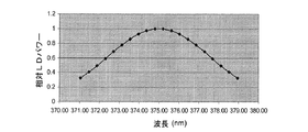
ファイバ6の出力端において光の特定のスペクトル分布を生成するには、コリメートレンズ7後段のビーム光路に検出器を介設した後、各LDを順次オンする一方でその他のLDはオフとし、各LDの駆動電流を調整して所要出力パワーのビームを得ることにより、各LDからのビームのスペクトル成分のパワーを測定する(あるいは、各LDのコリメートレンズ2と集光レンズ3間にシャッターを設け、レンズ7後段の検出器で測定しつつ各シャッターを順次開く一方でその他のシャッターは閉じることにより、個々のLDの出力パワーを測定するようにしてもよい。さらには、分光計を用いてレンズ7後段のビームのスペクトル成分を測定することにより、すべてのLDの出力パワーを同時に測定するようにしてもよい)。具体的には、発光波長λnに対する出力パワーPの依存性が以下の切頂ガウス分布で実質的に記述されるように、LDの出力パワーを調整する。
In order to generate a specific spectral distribution of light at the output end of the

本実施形態にかかるLDアレイ1から得られる様々な波長を考慮して、σ及びtは、それぞれ2.6nm及び1.5とする。これらの値により、LD出力パワーの中心波長依存性は、図4に示す通りとなる。各LDからのスペクトル帯域幅がおよそ1nmであれば、ファイバ6から現れる光の積分スペクトル組成は、図5に示す通りとなる。この分布の半値全幅(FWHM)は、純粋なガウス形からは幾分逸脱しており、6.2nmと判断される。
Considering various wavelengths obtained from the
照射によってフォトレジスト21に静止像が形成されるように、フォトレジストでコーティングされた基板20とマスク18間の離間距離を調整する。波長がλ0−wからλ0+wへと変化する単色ビーム(2wは分布のFWHM)によるマスクの(仮)照射によって、少なくとも中心波長λ0での照射で形成された強度分布のタルボ周期に対応した距離だけフォトレジスト21を照射する横強度分布が長手方向に変位するように離間距離が設定されている場合は、上述の準ガウス分布により、略静止像を形成する。これは、数学的には以下のように表される。
The separation distance between the photoresist-coated
タルボ周期は、波長と以下の関係にある。 The Talbot period has the following relationship with the wavelength.
![]()
![]()
最短隣接距離pのパターンフィーチャの六角形アレイの場合、1次回折次数の極角は、以下で求められる。 For a hexagonal array of pattern features with the shortest adjacent distance p, the polar angle of the first order diffraction order is determined as follows:
![]()
![]()
式(4)〜(6)から、基板とマスク間の離間距離が以下のように構成されている場合には、フォトレジストで静止像が形成されることが導かれる。 From Expressions (4) to (6), it is derived that a still image is formed with a photoresist when the distance between the substrate and the mask is configured as follows.
本実施形態に係る特定のパラメータ値(λ0=375nm、p=600nm、2w=6.2nm)でこの値を求めると、φ(λ0)=46.2°となるため、d≧50μmが得られる。当然のことながら、使用するレーザー光源から形成されるスペクトルプロファイルのFWHMが3.1nmであれば、マスクと基板間の離間距離は2倍必要となる。マスクと基板間の離間距離は、このようにその都度構成するのが好ましいが、特定用途で必要な印刷フィーチャのサイズの一様性に応じて、幾分か小さな離間距離を用いるようにしてもよい。 When this value is obtained with specific parameter values (λ 0 = 375 nm, p = 600 nm, 2w = 6.2 nm) according to the present embodiment, φ (λ 0 ) = 46.2 °, so that d ≧ 50 μm can get. As a matter of course, if the FWHM of the spectrum profile formed from the laser light source to be used is 3.1 nm, the distance between the mask and the substrate needs to be doubled. The separation between the mask and the substrate is preferably configured in this way, but a somewhat smaller separation may be used depending on the size uniformity of the print features required for a particular application. Good.
式(7)は、入射ビームのすべてのスペクトル成分を同じ効率でミラー14が反射することと、LDアレイ1とマスク18間のその他すべての光学素子も同じ効率でスペクトル成分を透過させることで、マスクを照射するスペクトル分布がLDアレイ1からの分布に対応することを前提としている。本発明の別の実施形態において、LDアレイとマスク間の光学素子が同じ効率で光の反射及び/又は透過を行わない場合は、個々のLDの出力パワーを適宜調整して光学的なスペクトル変調を補償する必要がある。また、式(7)のパラメータwは、LDアレイからの分布ではなく、マスクを照射するスペクトル分布のHWHMを表すものとする。
Equation (7) indicates that the
フィーチャの所要解像度がフォトレジストに印刷可能となるように、照射ビームは、十分にコリメートする必要がある。特に、マスクパターンの任意の点を照射する光線の角度範囲Δω(FWHM)は、以下を満足するのが好ましい。 The illumination beam must be sufficiently collimated so that the required resolution of the features can be printed on the photoresist. In particular, it is preferable that the angle range Δω (FWHM) of the light beam that irradiates an arbitrary point of the mask pattern satisfies the following.
![]()
![]()
本実施形態においては、印刷パターンにおける所要フィーチャサイズがマスクパターンの六角形アレイにおける孔の直径と同じであるため、マスクと基板間の離間距離がおよそ50μmに設定されている場合は、式(8)により、マスクパターンの任意の点を照射する入射角度範囲が2mR(FWHM)以下である必要がある。 In this embodiment, since the required feature size in the printed pattern is the same as the hole diameter in the hexagonal array of the mask pattern, when the separation distance between the mask and the substrate is set to about 50 μm, the equation (8) ), The incident angle range for irradiating an arbitrary point of the mask pattern needs to be 2 mR (FWHM) or less.
上述の光学系によるコリメーション度はおよそ2mRであるため、フォトレジスト21に印刷された静止像のおよそ300nmのフィーチャを解像するには十分である。ビームのコリメーション度が高くなると、フィーチャをより正確に規定可能となる。
Since the degree of collimation by the above-described optical system is approximately 2 mR, it is sufficient for resolving the approximately 300 nm feature of the still image printed on the
フォトレジスト21に静止像を印刷する場合にマスク18と基板20間で必要なこの最小離間距離は、マスク18を透過する光照射野のコンピュータシミュレーションによって決定及び/又は検証を行うようにしてもよい。この場合は、Grating Solver Development社が開発したGSolverやマサチューセッツ工科大学が開発したMEEP等の市販又は無料のソフトウェアを用いて、有限差分時間領域法(FTDT)や厳密結合波解析法(RCWA)等の標準的な手法を採用するようにしてもよい。ATL技術及びDTL技術によるこのようなシミュレーションツールのフォトリソグラフィ露光への適用については、米国同時係属出願第12/903,389号に詳しく記載されている。マスクと基板間の離間距離を50μmとして本実施形態の露光ビームでマスクパターン19を照射することにより形成したフォトレジスト層21における積分強度分布のコンピュータシミュレーション結果を図6に示す。図中の強度スケールから、分布中の強度ピークが高いコントラストを有し、デバイス製造において堅牢なリソグラフィプロセスを提供可能であることが分かる。基板20とマスク18間の離間距離をさらに大きくして焦点深度を深くできるように、強度分布が実際に安定すなわち不変であることを検証するため、マスク18と基板20間の離間距離を大きくした場合の関数として分布中心における強度を計算した。図7に示す結果から、離間距離が小さい場合は強度が急速に変化するが、離間距離がおよそ50μmを超えると基本安定値に達して(残留変動およそ±2%未満)、式(4)〜(6)で計算した最小所要離間距離に適合する。
This minimum distance required between the
ある露光時間にわたってマスク18が平行ビームで照射されて特定の露光エネルギー密度(すなわち照射線量)が伝達されるように、シャッター12を開いた後に閉じて露光を行う。ビームのすべての波長成分に対してフォトレジストも同時に露光されるため、照射線量のスペクトル分布は、ビームのスペクトル強度分布に対応する(すなわち、同じプロファイルを有する)。また、総照射線量は、線量スペクトル分布の積分であって、露光時間に比例する。現像したフォトレジスト21において照射線量が所望の構造を形成するように、露光時間を調整する。これは、フォトレジストでコーティングした多数の基板を様々な照射線量に露光して、光学顕微鏡又は走査型電子顕微鏡により印刷パターンを評価することで最適な線量を決定する方法等、標準的なフォトリソグラフィ技術で決定するようにしてもよい。
The exposure is performed after the
米国特許出願第13/035,012号には、切頂ガウスプロファイル、切頂正弦プロファイル、及び切頂三角形プロファイルに従って、フォトレジストでコーティングされた基板の変位増分当たりの照射線量を変化させることにより、実質的に同じ利点及び印刷結果が得られることが示されているが、この教示内容と同様に、LD出力パワーの出力波長依存性が(非)切頂正弦プロファイル及び(非)切頂三角形プロファイルのうちの一方と適合して、マスクを照射する光のスペクトル分布が同様に記述されるように、上記と同じ利点及び印刷結果を得るようにしてもよい。前者の場合、LDの出力パワーP(λn)は、発光波長λn依存性が次式で表されるように調整する必要がある。 U.S. Patent Application No. 13 / 035,012 discloses that by varying the dose per displacement increment of a photoresist coated substrate according to a truncated Gaussian profile, truncated sine profile, and truncated triangular profile, Although it has been shown that substantially the same benefits and printing results are obtained, similar to this teaching, the output wavelength dependence of the LD output power is a (non) truncated sine profile and a (non) truncated triangle profile. The same advantages and printing results as described above may be obtained so that the spectral distribution of the light that illuminates the mask is described in a similar manner, with one of the above. In the former case, it is necessary to adjust the output power P (λ n ) of the LD so that the emission wavelength λ n dependency is expressed by the following equation.
(非)切頂正弦プロファイルでは、照射波長をλ0−wからλ0+wへと変化させることによって、少なくとも中心波長λ0の光で形成された強度分布のタルボ周期に対応した距離だけフォトレジストを照射する横強度分布が長手方向に変位するように離間距離dが設定されている場合は、フォトレジストに静止像が形成される。こうなるのは、パラメータwが(非)切頂正弦プロファイルの半値半幅(HWHM)を表すものとして式(4)が満たされる場合である。 In the (non) truncated sine profile, by changing the irradiation wavelength from λ 0 −w to λ 0 + w, the photoresist is at least a distance corresponding to the Talbot period of the intensity distribution formed by the light having the center wavelength λ 0. When the separation distance d is set so that the lateral intensity distribution for irradiating is displaced in the longitudinal direction, a still image is formed on the photoresist. This is the case when equation (4) is satisfied where the parameter w represents the half width (HWHM) of the (non) truncated sine profile.
したがって、マスク中のフィーチャの六角形アレイから静止像を形成する場合にマスクと基板間で必要な最小離間距離は、式(7)を用いて計算するようにしてもよい。 Therefore, the minimum separation required between the mask and the substrate when forming a still image from a hexagonal array of features in the mask may be calculated using equation (7).
(非)切頂三角形プロファイルの場合、LDの出力パワーP(λn)は、発光波長λn依存性が次式で表されるように調整する必要がある。 In the case of the (non-) truncated triangular profile, the output power P (λ n ) of the LD needs to be adjusted so that the emission wavelength λ n dependency is expressed by the following equation.
(非)切頂三角形プロファイルでは、照射波長をλ0−wからλ0+wへと変化させることによって、少なくとも中心波長λ0の光で形成された強度分布のタルボ周期Tに対応した距離だけフォトレジストを照射する横強度分布が長手方向に変位するように離間距離dが設定されている場合は、フォトレジストに静止像が形成される。こうなるのは、パラメータwが(非)切頂三角形プロファイルのHWHMを表すものとして式(4)が満たされる場合である。 In the (non-) truncated triangular profile, by changing the irradiation wavelength from λ 0 −w to λ 0 + w, a photo is produced by a distance corresponding to at least the Talbot period T of the intensity distribution formed with light having the center wavelength λ 0. When the separation distance d is set so that the lateral intensity distribution irradiated with the resist is displaced in the longitudinal direction, a still image is formed on the photoresist. This is the case when equation (4) is satisfied where the parameter w represents the HWHM of the (non) truncated triangular profile.
したがって、マスク中のフィーチャの六角形アレイから静止像を形成する場合にマスクと基板間で必要な最小離間距離は、同じように式(7)を用いて計算するようにしてもよい。 Therefore, the minimum separation required between the mask and the substrate when forming a still image from a hexagonal array of features in the mask may be calculated using equation (7) in the same way.
このように、FWHMの値が同じガウスプロファイル、(非)切頂正弦プロファイル、及び(非)切頂三角形プロファイルのスペクトル分布では、マスクから略同じ距離で静止像が形成され、フォトレジストの印刷パターンも略同じとなる。 Thus, in the spectral distribution of the Gaussian profile, (non) truncated sine profile, and (non) truncated triangular profile with the same FWHM value, a still image is formed at substantially the same distance from the mask, and the photoresist print pattern Is almost the same.
上述の好適な切頂ガウスプロファイル、(非)切頂三角形プロファイル、及び(非)切頂正弦プロファイルの形状はすべて、中心ピークの波長の滑らかな関数であって、それぞれのFWHM値のおよそ2倍の全幅を有する点で類似している。したがって、当然のことながら、本発明の別の実施形態においては、これらと類似する別のスペクトル分布形状を採用してもよく、その場合も実質的に同じ利点及び印刷結果が得られることが予想される。たとえば、適当な台形プロファイルのスペクトル分布を採用してもよい。このような異なる分布では、式(7)及び/又はコンピュータシミュレーションにより、スペクトル分布のFWHM値からマスクとフォトレジストでコーティングされた基板間の露光中の最小離間距離を決定するのが好ましい。ATL像が形成される安定距離を推定するための補完方法では、スペクトル分布のフーリエ変換を考慮に入れるが、これについては本明細書中で後述する。 The shapes of the preferred truncated Gaussian profile, (non) truncated triangular profile, and (non) truncated sine profile described above are all smooth functions of the wavelength of the central peak, approximately twice the respective FWHM value. It is similar in that it has a full width. Thus, it will be appreciated that other embodiments of the present invention may employ other spectral distribution shapes similar to these, which would be expected to yield substantially the same advantages and print results. Is done. For example, an appropriate trapezoidal profile spectral distribution may be employed. For such different distributions, it is preferable to determine the minimum separation during exposure between the mask and the photoresist coated substrate from the FWHM value of the spectral distribution by equation (7) and / or computer simulation. The interpolation method for estimating the stable distance at which the ATL image is formed takes into account the Fourier transform of the spectral distribution, which will be described later in this specification.
照射ビーム及び/又は照射線量のスペクトル分布においては、2次的な複数のピークが抑えられているのが好ましい。このため、個々のレーザー光源からのビームのスペクトル幅は、昇順に並べた場合のピーク波長のスペクトル分離よりも大きければ、重畳するスペクトルプロファイル間が実質的に重複するため都合が良い。 In the spectral distribution of the irradiation beam and / or irradiation dose, it is preferable that a plurality of secondary peaks are suppressed. For this reason, if the spectral widths of the beams from the individual laser light sources are larger than the spectral separation of the peak wavelengths when arranged in ascending order, it is convenient because the overlapping spectral profiles substantially overlap.
上述の実施形態において、マスクのパターンが正方形アレイ又はハニカムアレイ等、別の対称性を有する2次元アレイもしくは平行なラインとスペースが交互に現れる1次元アレイの場合は、該当するアレイ種別に対応した式(7)の等価形態を導出して使用する必要がある。 In the above-described embodiment, when the mask pattern is a two-dimensional array having another symmetry, such as a square array or a honeycomb array, or a one-dimensional array in which parallel lines and spaces appear alternately, it corresponds to the corresponding array type. It is necessary to derive and use the equivalent form of equation (7).
マスクが1次元アレイを有する場合、スペクトルを混合したビームの経路中に偏光子を設けると都合が良くなる可能性がある。マスク照射光を格子線と平行な方向に偏光することによって、フォトレジストを露光する積分強度分布のコントラストが向上して、印刷フィーチャをより正確に規定可能となる。 If the mask has a one-dimensional array, it may be advantageous to provide a polarizer in the mixed beam path. By polarizing the mask irradiation light in a direction parallel to the lattice lines, the contrast of the integrated intensity distribution for exposing the photoresist is improved, and the print features can be defined more accurately.
図8を参照して、本発明の第2の実施形態においては、20個のレーザーダイオードの2次元4×5アレイ30が照射源に含まれ、各レーザーダイオードは、それぞれが制御回路を有しており、出力パワーを独立して調整可能である。LDは、それぞれの中心波長又はピーク波長がスペクトル範囲371〜379nmにわたって概ね同等の間隔(すなわち、およそ0.4nmの間隔)となり、各LDのスペクトル帯域幅が通常およそ1nmとなるように選択したものである。各LDからのビームは、yz平面よりもxy平面でより高速に発散するが、レンズ32に入射してコリメートされることにより、断面が楕円形のビームとなる。そして、このビームは、アナモルフィックプリズム対34を通過して、xy平面におけるビームの圧縮により、断面が略円形で直径がおよそ1mmの平行ビームとなる。各LDからの平行ビームは、円筒状マイクロレンズの第1のタンデムアレイ37を照射するように、ミラー36で偏向される。アレイ30中の別のLDからのビームについても同様に、ビーム成形アレイ33中の対応するレンズ及びアナモルフィックプリズム対によって平行化及び円形化された後、ミラーアレイ35中の対応するミラーで偏向されるため、すべてのビームが実質的に重畳することにより、マイクロレンズアレイ37において直径およそ2mmの照射スポットが形成される。マイクロレンズの開口数は、およそ±7°の様々な角度で光を屈折させるように設定されている。また、アレイ37は、yz平面で光を屈折させるように配向している。第1のマイクロレンズアレイ37から発散した光はその直後に、直交平面内で配向し、xz平面においておよそ±7°の様々な角度で光を屈折させる同じような第2のアレイ38に入射する。したがって、ビーム結合器としても作用するこれら2つのアレイ37、38からの発散光は、遠視野において、強度及びスペクトル分布が略一様な光の正方形分布を生成する。発生光中の「クロストーク」の問題を回避するため、マイクロレンズアレイ37、38に入射するビームの発散角は、xz平面及びyz平面の両者で±7°未満となるように構成されている。これは、アレイ30中のLD、ビーム成形アレイ33中のレンズ及びアナモルフィックプリズム、ならびにアレイ35中のミラーを1列ではなく2次元形状に配置することで容易となる。マイクロレンズアレイ37、38の前段の光路には、マイクロレンズアレイ37、38の周期構造を照射する各ビームの光の空間コヒーレンスを低減することで出力ビーム中の不要な干渉効果を抑えるため、拡散器40を備えているのが好ましい。拡散器40は、リソグラフィ露光中にマイクロレンズアレイ37、38の平面と垂直な軸周りに回転して時間積分露光を一様にするモーター(図示せず)に搭載されている。拡散器40の前段には、電子制御のシャッター41を追加して、アレイ30中のLDからのビームを同時に遮断することにより、リソグラフィ露光の継続時間を高精度かつ再現可能に制御できるようにする。マイクロレンズアレイ37、38からの発散ビームは、ミラー42によりレンズ44の方へ反射され、コリメートされた後、略垂直入射でマスク46中のパターン47を照射する。マスクパターン47は、第1の実施形態と同じである。タンデムアレイ37、38を照射する積分ビームの直径を考慮して、コリメートレンズ44の焦点距離は、マスクのパターンの各点を照射する光の角度範囲がおよそ2mRとなるように、およそ1mに選択されている。
Referring to FIG. 8, in the second embodiment of the present invention, a two-dimensional 4 × 5
マスク46の下方では、第1の実施形態と同じ機械装置及び間隙測定方法により、フォトレジストでコーティングされた基板48がマスク46と略平行に近接して配置されている。
Below the
マスク46を照射する光のスペクトル分布は、第1の実施形態と略同じ分布に調整されている。これは、検出器を用いて各LDからの平行ビームのパワーを測定した後、各LDの制御回路によりそれぞれの出力パワーを所要値に調整することによって、同等の方法で実現するようにしてもよい。マスク46とフォトレジストでコーティングされた基板48間の離間距離は、同じくおよそ50μmに調整されている。これは、マスクパターンの静止像を形成するのに必要であり、照射ビームのコリメーション度を所与として、印刷パターンのフィーチャが十分に解像されるようにするのにも必要である。また、露光は、第1の実施形態と本質的に同じ手順で実施する。
The spectral distribution of the light that irradiates the
六角形アレイの場合と同様に、マスクパターンが2次元の場合は、マスクを照射するビームが線形偏光されないように、偏光変換素子を光学系に設けると都合が良くなる可能性がある。各LDからの線形偏光平行ビームに1/4波長位相差板又はデポラライザを設けることにより、マスクを照射するビームの偏光が等方的に分散され、円孔等の回転対称フィーチャがフォトレジスト中で容易に形成される。 As in the case of the hexagonal array, when the mask pattern is two-dimensional, it may be convenient to provide a polarization conversion element in the optical system so that the beam irradiating the mask is not linearly polarized. By providing a ¼ wavelength phase difference plate or depolarizer to the linearly polarized parallel beam from each LD, the polarization of the beam irradiating the mask is isotropically dispersed, and rotationally symmetric features such as circular holes are formed in the photoresist. Easy to form.
別の実施形態においては、マスクを照射するビームが線形偏光されないように、アレイ中のLDを異なる配向で配置する。たとえば、半数のLDは、出力ビームの方向と平行な軸周りに90°回転させて搭載することにより、マスクを照射するビーム中の光の半分がある平面で偏光され、残りの半分が直交平面で偏光されるようにしてもよい。これにより、回転対称フィーチャの2次元パターンの印刷でも、略同じ利点が得られる。 In another embodiment, the LDs in the array are arranged in different orientations so that the beam illuminating the mask is not linearly polarized. For example, half of the LDs are mounted by rotating 90 ° about an axis parallel to the direction of the output beam, so that half of the light in the beam illuminating the mask is polarized in a plane and the other half is orthogonal It may be polarized with This provides substantially the same advantage for printing a two-dimensional pattern of rotationally symmetric features.
一方、マスクのパターンが1次元の場合は、静止像のコントラストが高くなるように、マスクを照射するビームが平面偏光されているのが好ましい。 On the other hand, when the mask pattern is one-dimensional, it is preferable that the beam irradiating the mask is plane-polarized so that the contrast of the still image is high.
本発明の別の実施形態においては、2n個のLDがある範囲Δλにわたり出力波長がおよそΔλ/(n−1)の等間隔で用いられており、各波長の値ごとに2つのLDを使用する。同様に、別の実施形態では、3n個又は4n個(又は、それ以上)のLDがある範囲Δλにわたり出力波長がおよそΔλ/(n−1)の等間隔で用いられており、各波長の値ごとに3つ又は4つのLDを使用する。
In another embodiment of the present invention, output wavelengths are used at equal intervals of approximately Δλ / (n−1) over a range Δλ of 2n LDs, and two LDs are used for each wavelength value. To do. Similarly, in another embodiment, the output wavelengths are used at equal intervals of approximately Δλ / (n−1) over a range Δλ of 3n or 4n (or more) LDs, with each
上述の実施形態では、中心波長がある範囲にわたって等間隔となり、相対出力パワーが所要スペクトル分布に従って調整されるようにレーザー光源が選択されているが、本発明の別の実施形態では、単位波長間隔当たりのレーザー数が様々な波長で変化するとともに、出力パワーが好ましくは略同じ値に調整されることによって、結合ビームの積分スペクトル分布が所望の準ガウス分布又はその他のプロファイルに対応するようにレーザーが選択されている。 In the above embodiment, the laser light source is selected such that the center wavelengths are equally spaced over a range and the relative output power is adjusted according to the required spectral distribution, but in another embodiment of the invention the unit wavelength spacing As the number of lasers hit varies at different wavelengths, the output power is preferably adjusted to approximately the same value, so that the integrated spectral distribution of the combined beam corresponds to the desired quasi-Gaussian distribution or other profile. Is selected.
本発明の別の実施形態においては、LDの出力パワーが略同じ値に調整されており、好ましくは最初の結合及びコリメートの後に、スペクトル透過曲線が所要分布に対応したフィルタへと出力ビームが誘導され、この透過ビームによってマスクを照射している。同様かつ同等の実施形態においては、好ましくは最初の結合及びコリメートの後に、スペクトル反射曲線が所要分布に対応した反射フィルタ上へと出力ビームが誘導され、この反射ビームによってマスクを照射している。 In another embodiment of the invention, the output power of the LD is adjusted to approximately the same value, preferably after the first coupling and collimation, the output beam is directed to a filter whose spectral transmission curve corresponds to the required distribution. The mask is irradiated with the transmitted beam. In a similar and equivalent embodiment, preferably after the first combination and collimation, the output beam is directed onto a reflection filter whose spectral reflection curve corresponds to the required distribution and illuminates the mask with this reflected beam.
上述の実施形態において、照射ビームは露光中に変化せず、これが好ましくはあるが、露光中にマスク全体にわたってスキャンするようにしてもよい。この場合は、マスクパターン上の時間積分露光密度が略一様となるように、ビームの断面強度プロファイル及びスキャン動作を構成するのが好ましい。 In the embodiments described above, the irradiation beam does not change during exposure, which is preferred, but it may be scanned across the mask during exposure. In this case, it is preferable to configure the beam cross-sectional intensity profile and the scanning operation so that the time-integrated exposure density on the mask pattern is substantially uniform.
本発明のさらに別の実施形態においては、波長ごとにマスクの露光時間を変化させて、照射波長での照射線量の全部又は一部を必要に応じて変化させている。これは、たとえば各LDからの出力ビームのパワーを略同じ値に調整した後、LDからのビーム光路に設けられた独立制御可能なシャッターにより(あるいは、各LDを個別にオン/オフ切り替えすることにより)、たとえば準ガウス分布に従って、各LDからの光へのマスク露光時間を波長とともに変化させることにより行うようにしてもよい。また、異なる波長の光がマスクを照射する時間の周期は、総露光時間が最小となるように重複しているのが好ましい。ただし、連続していてもよい。本実施形態の変形例においては、各LDからのビームが略同じ瞬時パワーを有するものの、その光は、所望の準ガウス分布又はその他の分布に従って、好ましくは一定周波数かつ波長とともに変化するデューティサイクル(これにより時間平均パワーが決まる)を有するパルスで与えられる。各LDからのビームのこのようなパルス化は、ビーム光路に設けられた電子制御のシャッターを用いるか、又はLDをオン/オフ切り替えすることによって実現するようにしてもよい。あるいは、パワーの高値とゼロ値間ではなく、高値と低値間でパルス化を行うようにしてもよい。また、同じ目的で、各LDからのパワーのアナログ変調を利用してもよい。 In yet another embodiment of the present invention, the exposure time of the mask is changed for each wavelength, and all or part of the irradiation dose at the irradiation wavelength is changed as necessary. This is because, for example, the power of the output beam from each LD is adjusted to substantially the same value, and then each LD is individually switched on / off by an independently controllable shutter provided in the beam optical path from the LD. For example, according to a quasi-Gaussian distribution, the mask exposure time for the light from each LD may be changed with the wavelength. Moreover, it is preferable that the period of time when the light of different wavelengths irradiates the mask is overlapped so that the total exposure time is minimized. However, it may be continuous. In a variation of this embodiment, although the beams from each LD have substantially the same instantaneous power, the light preferably follows a desired quasi-Gaussian or other distribution, preferably at a constant frequency and a duty cycle that varies with wavelength ( This determines the time average power). Such pulsing of the beam from each LD may be realized by using an electronically controlled shutter provided in the beam optical path or by switching the LD on and off. Alternatively, pulsing may be performed between the high value and the low value instead of between the high value and the zero value of the power. For the same purpose, analog modulation of power from each LD may be used.
別の実施形態においては、上述の実施形態に記載のように個々のLDからのビームが重畳して単一の略一様なビームとはならず、結合されて複合ビームとなる。この場合、異なるLDからの平行サブビームは、空間的に区別された状態のままで、略平行である。また、サブビーム中の光のパワーの波長依存性は、所要の線量スペクトル分布に対応するように構成されている。そして、異なる波長の各サブビームに対してマスクパターンが一様に露光され、その結果として所望のスペクトル分布に一様に露光されるように、一定の入射角度でマスク全体にわたり複合ビームをスキャンしてリソグラフィ露光を行う。本実施形態では、異なる波長に対して、同時ではなく連続してマスクパターンを露光する。 In another embodiment, the beams from the individual LDs do not overlap to form a single substantially uniform beam as described in the above embodiments, but are combined into a composite beam. In this case, parallel sub-beams from different LDs are substantially parallel while remaining spatially distinguished. Further, the wavelength dependence of the light power in the sub-beam is configured to correspond to a required dose spectrum distribution. The composite beam is then scanned across the mask at a constant angle of incidence so that the mask pattern is uniformly exposed for each sub-beam of a different wavelength, resulting in a uniform exposure to the desired spectral distribution. Lithographic exposure is performed. In the present embodiment, the mask pattern is exposed to different wavelengths continuously instead of simultaneously.
本発明の別の実施形態においては、独立した冷却機構(熱電冷却等)により各LDの温度を個別に調整することによって、たとえばLDの中心波長が範囲上で高精度に等間隔となるように出力ビームの中心波長を所要の値に微調整する。あるいは、露光中に高値と低値間でLDの温度を振動させることによって、各LDの時間積分スペクトルを広げることで、準ガウス分布又は所望のFWHMを有する類似のスペクトルプロファイルの複合ビームの形成に必要なLD数を低減するようにしてもよい。また、このようなLDの温度振動を用いることにより個々のLDのスペクトル中の考え得る微細構造の影響を抑えて、複数のLDからの時間積分複合スペクトルが所望のプロファイルにより近くなるようにしてもよい。さらには、個々のLDのスペクトル間の重複を大きくして、積分スペクトル中の2次的又は複数のピークを抑制さらには除去する。 In another embodiment of the present invention, by adjusting the temperature of each LD individually by an independent cooling mechanism (thermoelectric cooling or the like), for example, the center wavelength of the LD is evenly spaced with high accuracy over the range. Fine-tune the center wavelength of the output beam to the required value. Alternatively, by widening the time-integrated spectrum of each LD by oscillating the temperature of the LD between high and low values during exposure, a composite beam with a similar spectral profile with a quasi-Gaussian distribution or the desired FWHM is formed. The required number of LDs may be reduced. Further, by using such temperature oscillation of the LD, the influence of a possible fine structure in the spectrum of each LD is suppressed, and the time-integrated complex spectrum from a plurality of LDs is made closer to a desired profile. Good. Furthermore, the overlap between the spectra of individual LDs is increased to suppress or remove secondary or multiple peaks in the integrated spectrum.
あるいは、露光中にLDの駆動電流を振動させることによって、同じように個々のLDの時間積分スペクトルの拡大及び/又は微細構造の抑制を図るようにしてもよい。各LDからの時間積分スペクトルの形状は、要求に応じて各振動中の駆動電流変化プロファイルを選択することにより、さらに変更するようにしてもよい。 Alternatively, the time integration spectrum of each LD may be expanded and / or the fine structure may be suppressed in the same manner by vibrating the LD drive current during exposure. The shape of the time integration spectrum from each LD may be further changed by selecting a drive current change profile during each vibration as required.
別の実施形態においては、結合ビームの積分スペクトル分布が所望のプロファイルに十分近くなるように出力ビームの相対パワーを調整することによって(パワー分布が波長の等間隔を前提として厳密に計算されない)、たとえば範囲上でレーザー光源の実中心波長が等間隔となるための所望の値からの実中心波長のオフセットがある程度は補償されている。 In another embodiment, by adjusting the relative power of the output beam so that the integrated spectral distribution of the combined beam is sufficiently close to the desired profile (the power distribution is not strictly calculated assuming equal wavelength spacing) For example, the offset of the actual center wavelength from a desired value for equalizing the actual center wavelength of the laser light source over the range is compensated to some extent.
上述の実施形態で選択されたLDが多重横モードで発光して出力ビームが相対的に高いパワーを有することは、マスク及びフォトレジストの露光時間最小化という利点であるのに対して、別の実施形態においては、単一横モードで発光するレーザーを採用してもよい。 The fact that the LD selected in the above embodiment emits light in multiple transverse modes and the output beam has a relatively high power is an advantage of minimizing the exposure time of the mask and the photoresist. In the embodiment, a laser that emits light in a single transverse mode may be employed.
また、上述の実施形態では、異なるレーザー光源からの発光を結合して、マスク中の周期パターンを照射する単一のスペクトル一様なビームを形成するため、光ファイバ及びマイクロレンズアレイをそれぞれ採用しているが、当然のことながら、本発明の別の実施形態においては、他のビーム結合手段を採用して同様又は類似の結果を得るようにしてもよい。 Further, in the above-described embodiment, an optical fiber and a microlens array are respectively employed to combine light emitted from different laser light sources to form a single spectrum uniform beam that irradiates the periodic pattern in the mask. However, it will be appreciated that other beam combining means may be employed in other embodiments of the present invention to achieve similar or similar results.
同様に、上述の実施形態では、マイクロレンズアレイを採用して、マスクパターン全体にわたって強度が極めて一様な照射ビームを生成しているが、別の実施形態においては、同じ目的で他の手段を採用するようにしてもよい。たとえば、第1の実施形態のファイバ6からの発散ビームは、実質的にガウス角度分布を有するが、これをまずはコリメートした後、屈折型ガウス/長方形ビーム変換器に誘導して、強度分布が略一様な出力ビームを生成し、その後、ビームをさらに拡張してマスクの照射に必要なビームサイズ及びコリメーション度を得るようにしてもよい。
Similarly, in the above-described embodiment, a microlens array is used to generate an irradiation beam having a very uniform intensity over the entire mask pattern. However, in another embodiment, other means are used for the same purpose. You may make it employ | adopt. For example, the divergent beam from the
上述の実施形態では、異なる波長の多数のレーザーからのビームを結合して、個々のレーザーよりも大きなスペクトル帯域幅及び収色性タルボリソグラフィの原理に従ってフォトリソグラフィ露光を行う際の所望のスペクトル形状を有する一様なビームを形成するため、レーザー光源とマスク間の光学系を構築・採用しているが、略同じ光学系を採用することによって、略同じ中心波長を有する多数のレーザーからの出力ビームを結合して個々のレーザーと略同じ単色スペクトルプロファイルを有する高強度の一様なビームを形成することにより、変位タルボリソグラフィの原理に従ったリソグラフィ露光を行うようにしてもよい。このような高強度のビームには、露光時間の短縮によって、単一レーザーを用いる場合よりも高いウェハースループットが得られるという利点がある。このような実施形態においては、たとえば375nmの中心波長(及び、およそ1nmのスペクトル帯域幅)を有する20個のレーザーのセットを用いるようにしてもよい(これについても、日亜化学工業製のものが利用可能である)。スペクトルプロファイルの形状に関しては、DTLの要件はATLとは異なるため、レーザーの駆動電流は、出力パワーが略同じになるように調整するようにしてもよい。当然のことながら、この用途でも、光学系のスペクトルフィルタによって、結合ビーム中の光のスペクトル分布形状を変更する必要はない。 In the above-described embodiment, beams from multiple lasers of different wavelengths are combined to give a desired spectral shape for photolithography exposure according to the principles of spectral bandwidth and color-collecting Talbotlithography larger than individual lasers. In order to form a uniform beam, an optical system between the laser light source and the mask is constructed and adopted. By adopting substantially the same optical system, output beams from many lasers having substantially the same center wavelength May be combined to form a high-intensity uniform beam having substantially the same monochromatic spectral profile as the individual lasers to perform lithographic exposure according to the principle of displacement Talbot lithography. Such a high-intensity beam has the advantage that a higher wafer throughput can be obtained by using a shorter exposure time than when a single laser is used. In such an embodiment, for example, a set of 20 lasers with a central wavelength of 375 nm (and a spectral bandwidth of approximately 1 nm) may be used (also from Nichia Corporation). Is available). Regarding the shape of the spectrum profile, since the DTL requirement is different from that of the ATL, the laser drive current may be adjusted so that the output power is substantially the same. Of course, even in this application, it is not necessary to change the spectral distribution shape of the light in the combined beam by the spectral filter of the optical system.
マスクとウェハー間の離間距離が露光中に変化するDTL型の露光を行うには、大きなスペクトル帯域幅及び様々な出力中心波長を有する複数のレーザーから生成された所要形状を有する照射ビームと、上述の実施形態に示したような露光システムとを採用するようにしてもよい。このような露光は、略単色のビームで周期パターンを照射する従来技術に係るDTL露光に対して一定の利点がある。具体的には、マスクと垂直な方向に生成された光照射野の強度変化が周期型から大幅に逸脱していると都合が良い。これが起こるのは、たとえばマスクとウェハー間の光照射野に2次以上の回折次数も存在して、0次回折次数と1次回折次数間の光学干渉を変調させている場合である。また、露光中にマスクとウェハー間の離間距離を変化させる手段が十分に精密ではないか、又は露光プロセスの継続時間と高精度に同期していなければ都合が良くなる可能性がある。いずれの場合も、印刷パターンが非一様及び/又は再現不可能となる可能性がある。このことは、マスクからの距離の関数として強度が高速及び/又は大きく振動することによって、特に悪化する。より広いスペクトル分布を有するビームでマスクを照射することにより、DTL型露光で得られる結果は大幅に改善する。これは、ATL露光で製造されたマスクと垂直な方向の透過光照射野の強度振動を考慮することによって理解可能である。すなわち、強度振動の振幅は、マスクからの距離の関数として小さくなり、ATLに係る静止像を得るのに必要な距離よりもはるかに小さな距離で相対的に小さな値に達する。また、強度分布の高周波振動の振幅は、2次以上の回折次数で生成されるものであるが、マスクからの距離が大きくなると、タルボ距離で特徴付けられる基本的な強度振動よりも急速に小さくなる。したがって、本発明の実施形態に示した露光システムを用いて様々な波長を有する複数のレーザー光源からのビームを結合することにより生成された広いスペクトル分布を有する照射ビームを用いてDTL法を実施すると、印刷パターンの再現可能性及び一様性が高くなる。この技術を代替又は追加とすることで、印刷パターンの特定の再現可能性及び一様性を得るための従来技術に要する精度と比較して、DTL変位の所要精度は低く抑えることができる。 In order to perform DTL type exposure in which the separation distance between the mask and the wafer changes during exposure, the irradiation beam having the required shape generated from a plurality of lasers having a large spectral bandwidth and various output center wavelengths, The exposure system as shown in the embodiment may be adopted. Such exposure has certain advantages over DTL exposure according to the prior art in which a periodic pattern is irradiated with a substantially monochromatic beam. Specifically, it is convenient if the intensity change of the light irradiation field generated in the direction perpendicular to the mask deviates significantly from the periodic type. This occurs when, for example, a second or higher diffraction order is also present in the light irradiation field between the mask and the wafer, and optical interference between the zeroth and first order diffraction orders is modulated. It may also be advantageous if the means for changing the separation between the mask and wafer during exposure is not sufficiently precise or not synchronized with the duration of the exposure process with high accuracy. In either case, the printed pattern may be non-uniform and / or non-reproducible. This is particularly exacerbated by the fact that the intensity oscillates fast and / or greatly as a function of distance from the mask. By irradiating the mask with a beam having a broader spectral distribution, the results obtained with DTL-type exposure are greatly improved. This can be understood by considering the intensity vibration of the transmitted light field in the direction perpendicular to the mask manufactured by ATL exposure. That is, the amplitude of the intensity vibration decreases as a function of the distance from the mask and reaches a relatively small value at a distance much smaller than the distance necessary to obtain a still image associated with the ATL. In addition, the amplitude of the high-frequency vibration in the intensity distribution is generated with a second or higher diffraction order. However, as the distance from the mask increases, the amplitude decreases more rapidly than the basic intensity vibration characterized by the Talbot distance. Become. Therefore, when the DTL method is performed using an irradiation beam having a wide spectral distribution generated by combining beams from a plurality of laser light sources having various wavelengths using the exposure system shown in the embodiment of the present invention. The reproducibility and uniformity of the print pattern is increased. By substituting or adding this technology, the required accuracy of DTL displacement can be kept low compared to the accuracy required for the prior art to obtain specific reproducibility and uniformity of the printed pattern.
これらの利点を以下の例によりさらに詳述する。最短隣接距離900nmの孔の六角形パターンを有する振幅マスクに対して、中心波長365nmのビームを照射する。第1の場合として、単色光ビームでマスクを照射する。第2の場合として、FWHM幅4.7nmのガウススペクトルを有するビームでマスクを照射する。図9は、これら2つの場合の照射に関して、マスクからの距離(間隔100〜110μm)の関数としての透過光照射野の強度の依存性を示した図である。「プロット1」及び「プロット2」はそれぞれ、単色光及びガウススペクトルの場合に相当する。強度振動の振幅は、第2の場合におよそ4倍小さくなっていることが分かる。また、第1の場合に存在する高周波振動が第2の場合には存在しない。したがって、ガウススペクトルの照射によるDTL法では、積分距離の変動及び積分の開始距離に対する印刷パターンの感度が低下する。
These advantages are further detailed by the following examples. A beam having a central wavelength of 365 nm is irradiated on an amplitude mask having a hexagonal pattern of holes having a shortest adjacent distance of 900 nm. In the first case, the mask is irradiated with a monochromatic light beam. In the second case, the mask is irradiated with a beam having a Gaussian spectrum with a FWHM width of 4.7 nm. FIG. 9 is a diagram showing the dependence of the intensity of the transmitted light field as a function of the distance from the mask (spacing 100 to 110 μm) with respect to irradiation in these two cases. “
本発明の別の実施形態においては、スペクトル分布のフーリエ変換を考慮することによって、フォトレジストでコーティングされた基板のマスクからの距離がさらに大きくなっても略不変の安定した静止像を得るためのスペクトル分布の所要形状を決定するようにしてもよい。上述の通り、マスクからの距離の関数としての像の安定性は、ビームのスペクトル及び格子の詳細を考慮に入れた電磁シミュレーションによって求めることができる。また、z方向に沿った強度振動の振幅を推定するのに、格子を透過した光のスペクトルのフーリエ変換を利用することもできる。たとえば、純粋な単色光ビームの場合は、フーリエ変換が一定のインパルス関数でスペクトルを表すことができる。したがって、純粋な単色光照射の場合は、強度振動が一定の振幅で無限に続く。 In another embodiment of the present invention, a Fourier transform of the spectral distribution is taken into account to obtain a stable still image that is substantially unchanged even when the distance from the mask of the substrate coated with the photoresist is further increased. The required shape of the spectral distribution may be determined. As described above, the stability of the image as a function of distance from the mask can be determined by electromagnetic simulation taking into account beam spectrum and grating details. Also, the Fourier transform of the spectrum of the light transmitted through the grating can be used to estimate the amplitude of the intensity vibration along the z direction. For example, in the case of a pure monochromatic light beam, the Fourier transform can represent the spectrum with a constant impulse function. Therefore, in the case of pure monochromatic light irradiation, the intensity vibration continues infinitely with a constant amplitude.
さらに別の例として、z軸に沿った強度振動とビームスペクトルのフーリエ変換との間の関係を図10、図11、及び図12に示す。この例では、最短隣接距離720nmの孔の六角形配置を有する2次元格子に方形波スペクトルの光を照射する。図10に示すように、このスペクトルの中心波長は365nmであり、幅は4nmである。図11はこのスペクトルのフーリエ変換の絶対値を示しており、図12は光軸に沿って計算した強度分布を示している。このプロット中の強度は、マスクにおける1つの孔の中心に対応した点で計算したものである。フーリエ変換と強度振動との間の対応が顕著に表れている。一般的に、距離zにおける強度振動の振幅は、当該z値に対応した空間周波数におけるスペクトルのフーリエ変換を計算することによっておおよそ推定可能である。この対応は、以下の関係で求められる。 As yet another example, the relationship between intensity oscillations along the z-axis and the Fourier transform of the beam spectrum is shown in FIG. 10, FIG. 11, and FIG. In this example, light having a square wave spectrum is irradiated onto a two-dimensional grating having a hexagonal arrangement of holes having a shortest adjacent distance of 720 nm. As shown in FIG. 10, the center wavelength of this spectrum is 365 nm and the width is 4 nm. FIG. 11 shows the absolute value of the Fourier transform of this spectrum, and FIG. 12 shows the intensity distribution calculated along the optical axis. The intensity in this plot is calculated at the point corresponding to the center of one hole in the mask. The correspondence between the Fourier transform and the intensity vibration is prominent. In general, the amplitude of the intensity vibration at the distance z can be roughly estimated by calculating the Fourier transform of the spectrum at the spatial frequency corresponding to the z value. This correspondence is required by the following relationship.
ここで、例を挙げてこの方法の使用方法を詳細に説明する。たとえば、最短隣接距離720nmの孔の六角形アレイを印刷したい場合で、照射ビームの中心波長が365nmであるものと仮定する。さらには、ATL法により、マスクからおよそz=100μm以上の距離でこのパターンを印刷したいものと仮定する。式(11)から、この距離に対応した空間周波数がf=0.175nm-1と計算される。したがって、スペクトルのフーリエ変換は、0.175nm-1以上の空間周波数に対して有意な強度を有していないはずである。このフーリエ変換法と式(7)に導入した基準との比較として、距離100μmを超えて静止像を与えるスペクトルの幅wを計算する。式(6)を用いると、この例の上述した印刷要求を満足するには、FWHM(2w)が5.7nmのガウス状スペクトルが必要であることが分かる。また、上記の式により計算した空間周波数(f=0.175nm-1)が式(7)で計算したFWHMの逆数f=1/2wに等しいことが分かる。したがって、いずれの方法でも同様の結果が得られる。式(7)はガウス状の滑らかなスペクトルの場合に特に適しているが、たとえば複数のピークを有するスペクトル等のより複雑なスペクトルの場合は、強度振動の様子及び所要の安定距離を推定する方法としてフーリエ変換法の使用が好ましい。フーリエ変換法は、電磁シミュレーションが不要なため、都合良く利用可能である。たとえばMathWorks社が開発したMatlabソフトウェア等、多くの市販ソフトウェアツールがフーリエ変換機能を備えており、所与のスペクトルに関する計算を容易に実行可能である。 Here, an example is given and the usage method of this method is demonstrated in detail. For example, assume that a hexagonal array of holes with the shortest adjacent distance of 720 nm is to be printed, and that the center wavelength of the illumination beam is 365 nm. Furthermore, it is assumed that it is desired to print this pattern at a distance of approximately z = 100 μm or more from the mask by the ATL method. From equation (11), the spatial frequency corresponding to this distance is calculated as f = 0.175 nm −1 . Therefore, the Fourier transform of the spectrum should not have significant intensity for spatial frequencies above 0.175 nm −1 . As a comparison between this Fourier transform method and the standard introduced in equation (7), the width w of the spectrum that gives a still image over a distance of 100 μm is calculated. Using equation (6), it can be seen that a Gaussian spectrum with a FWHM (2w) of 5.7 nm is required to satisfy the above-described printing requirements of this example. Further, it can be seen that the spatial frequency (f = 0.175 nm −1 ) calculated by the above equation is equal to the reciprocal f = ½w of FWHM calculated by the equation (7). Therefore, the same result can be obtained by either method. Equation (7) is particularly suitable for a Gaussian smooth spectrum, but in the case of a more complex spectrum such as a spectrum having a plurality of peaks, a method of estimating the state of intensity oscillation and the required stable distance. It is preferable to use the Fourier transform method. Since the Fourier transform method does not require electromagnetic simulation, it can be used conveniently. Many commercial software tools, such as Matlab software developed by MathWorks, for example, have a Fourier transform function and can easily perform calculations on a given spectrum.
一般的な指針として使用すべきは、スペクトル幅に基づいて式(7)により求められた推定又は上述したスペクトルのフーリエ変換である。また、振動の振幅は一般に、フィーチャサイズ等のマスクパターンの詳細ならびにフィーチャの位相シフト及び/又は減衰特性によって決まる。さらに、マスクからの距離の増大に伴う強度振動の許容値には、用途に応じた要件及びフォトレジストプロセスの特性も影響する。したがって、プロセスの要件に応じて、格子及び用途の詳細を考慮した適当な電磁計算により、像コントラストと併せて特定の距離における振動振幅を決定するようにしてもよい。また、フォトレジスト中の予想パターンの計算は、このような光学計算の結果を用いて、当該フォトレジスト向けに設計されたシミュレーションツールにより行うようにしてもよい。 What should be used as a general guideline is the estimation obtained by equation (7) based on the spectral width or the Fourier transform of the spectrum described above. Also, the amplitude of vibration generally depends on details of the mask pattern, such as feature size, and the phase shift and / or attenuation characteristics of the feature. Furthermore, the tolerance of the intensity vibration accompanying the increase in the distance from the mask is affected by the requirements according to the application and the characteristics of the photoresist process. Thus, depending on the process requirements, the vibration amplitude at a specific distance may be determined in conjunction with the image contrast by appropriate electromagnetic calculations taking into account the grid and application details. The calculation of the expected pattern in the photoresist may be performed by a simulation tool designed for the photoresist using the result of such optical calculation.
本発明の教示内容は、マスクと基板間の離間距離の許容範囲や所望の露光時間等、リソグラフィ用途のその他要件も考慮に入れつつ、露光システムの設計に適用してもよい。このような設計の場合は、たとえば印刷する周期パターンの種類や周期、マスクとフォトレジストコーティング基板間の許容離間距離、印刷可能な最大パターン面積、フォトレジストの感度、及び所望の露光時間等、露光システムの仕様をまず初めに規定する。マスクとウェハー間の離間距離の許容範囲は、マスクとウェハー間の接触に起因する損傷の回避及び粒子汚染又はウェハーの非平坦性に対する一定許容値の規定の必要に応じて影響を受ける場合がある。そして、これらのシステム仕様に基づいて、特に照射野面積A、照射強度Φ、直交平面におけるビーム光線の角度範囲(すなわち、デコリメーション度)θ、及びスペクトル分布の帯域幅(好ましくはFWHM値)w等、マスクにおいて必要な照射条件を決定するようにしてもよい。所要照射強度は、フォトレジストの感度、フォトマスクの透過性、及び目標露光時間によって決まる。また、所要コリメーション度は、印刷パターンの目標解像度によって決まり、式(8)を用いて決定してもよい。また、照射ビームの所要スペクトル帯域幅は、静止像を形成するマスクからの距離によって決まり、式(7)を用いて推定してもよい。 The teachings of the present invention may be applied to the design of an exposure system, taking into account other requirements for lithography applications, such as the acceptable range of separation between the mask and the substrate and the desired exposure time. In the case of such a design, for example, the type and period of the periodic pattern to be printed, the allowable separation distance between the mask and the photoresist coating substrate, the maximum pattern area that can be printed, the sensitivity of the photoresist, the desired exposure time, etc. System specifications are defined first. The tolerance of the separation distance between the mask and the wafer may be affected as necessary to avoid damage caused by contact between the mask and the wafer and to define a certain tolerance for particle contamination or wafer non-planarity . Based on these system specifications, in particular, the irradiation field area A, the irradiation intensity Φ, the angle range (that is, the degree of decoration) θ of the beam in the orthogonal plane, and the bandwidth of the spectral distribution (preferably the FWHM value) w The irradiation conditions necessary for the mask may be determined. The required irradiation intensity is determined by the sensitivity of the photoresist, the transparency of the photomask, and the target exposure time. Further, the required degree of collimation is determined by the target resolution of the print pattern, and may be determined using Expression (8). The required spectral bandwidth of the irradiation beam is determined by the distance from the mask that forms the still image, and may be estimated using equation (7).
上述の実施形態で説明したように、本発明を実施するのに適したレーザー光源は、様々な出力波長を有するレーザーダイオードのセットである。このようなレーザーの出力特性は、利用可能な波長の範囲λmin〜λmax、該当する波長に関して各レーザーで利用可能な最大パワーPλ、該当する波長に関する各レーザーの出力パワーの駆動電流依存性Pλ=fλ(l)、各レーザーからのビームのスペクトル線幅Δλ、及び発散ビームの平面におけるビーム断面と当該平面における断面の各点を通る光線の立体角との積として規定可能なビームの面積sを考慮して定義するようにしてもよい(Δλ及びsはいずれも、異なるレーザーに対して略同じと仮定してもよい)。そして、この定義と、レーザーとマスク間の光学系の透過効率の推定値εとに基づいて、目標とする仕様を実現するための上記所定のスペクトル分布及びビーム強度を生成するのに必要なレーザー数N、ピーク波長λ1、λ2、・・・λN、及び駆動電流I1、I2、・・・INを選択可能である。基本的な光学原理によれば、光学系を伝搬する光の面積は、保存又は増大する。すなわち、減少することはない(空間フィルタリング又はその同等作用により光が損失していないものと仮定)。したがって、マスクを照射するビームの面積Sは、異なるレーザー光源からのビームの面積の合計を下回ることはない。すなわち、
![]()
![]()
![]()
![]()
この条件が満たされない場合、N個のレーザー光源からのビームは、(少なくとも光の空間フィルタリングや許容範囲外のレーザーパワー損失があれば)結合して断面積A及びデコリメーション度θのビームを生成することはできない。このような場合は、妥協が必要となる。たとえば、結合ビーム中の光は、空間フィルタリングによって面積を小さくすることにより、上記の式の左辺を小さくするようにしてもよい。あるいは、レーザー数を削減してもよい。後者を選択した場合は、スペクトル幅への影響を考慮する必要がある。たとえば、スペクトル幅が小さくなると、マスクとウェハー間の離間距離を大きくする必要があるため、より小さなビームのデコリメーションが必要となる場合がある。また、いずれの場合も、照射ビームの強度が低下するため、露光時間及びシステムスループットに悪影響が出る。 If this condition is not met, the beams from the N laser sources will combine to produce a beam with cross-sectional area A and decorrelation degree θ (at least if there is spatial filtering of the light or laser power loss outside the acceptable range). I can't do it. In such cases, a compromise is necessary. For example, the left side of the above equation may be reduced by reducing the area of the light in the combined beam by spatial filtering. Alternatively, the number of lasers may be reduced. When the latter is selected, it is necessary to consider the influence on the spectral width. For example, as the spectral width becomes smaller, it may be necessary to increase the separation between the mask and the wafer, which may require smaller beam decoration. In either case, since the intensity of the irradiation beam is reduced, the exposure time and system throughput are adversely affected.
さらに、N個のレーザー光源からのビームを結合するために用いる手段に応じて、結合ビーム中の光の面積が式(13)の右辺のNsよりも実質的に大きくなる場合がある。したがって、条件違反の場合はシステム仕様の再考が当然必要であるが、違反していなくても、マスクにおけるビームサイズやデコリメーション角の観点では、照射要件が確実に満たされるわけではない。したがって、式(13)は最小要件を表しており、システム設計に応じて拡大する必要がある。特定の場合においては、実用上の制約及び設計関連の制約によって、(少なくとも許容範囲外のパワー損失があれば)ビームを結合して結果的に面積Nsを有することができなくなる場合もある。 Furthermore, depending on the means used to combine the beams from the N laser light sources, the area of the light in the combined beam may be substantially larger than Ns on the right side of equation (13). Therefore, if the condition is violated, it is naturally necessary to reconsider the system specification. Even if the condition is not violated, the irradiation requirement is not surely satisfied in terms of the beam size and the decoration angle in the mask. Therefore, equation (13) represents the minimum requirement and needs to be expanded depending on the system design. In certain cases, due to practical and design related constraints, the beams may not be combined (and at least with an unacceptable power loss) resulting in an area Ns.
本発明の教示内容に基づくリソグラフィ露光システムの設計に利用可能な上記一連のステップ手順を図13のフローチャートに示す。当然のことながら、これの代わりに別の設計方法を採用してもよい。 The above sequence of steps that can be used to design a lithographic exposure system based on the teachings of the present invention is shown in the flowchart of FIG. As a matter of course, another design method may be adopted instead.
上記詳述した第1の実施形態の場合、使用するレーザー光源の数は20個であり、各LDの発光断面はおよそ10μm2であり、直交平面における各LDからの出力ビームの発散は通常およそ15°×30°(FWHM値)である。このため、出力ビームの総面積すなわち式(13)の右辺は、およそ0.3cm2mR2となる。一方、第1の実施形態においてマスクを照射するビームの面積はおよそ225cm2(レンズ口径による欠失は一切無視)であり、ビーム中のコリメーション度は各平面においておよそ1.4mRである。このため、マスクを照射するビームの面積すなわち式(13)の左辺は、およそ440cm2mR2である。したがって、式(13)で表される条件は容易に順守され、当該要件を実現する光学系の設計が可能であることを裏付けている。また、式(13)の右辺は、第1の実施形態の光学系における中間位置で計算することにより、総面積が光学系の一部で大きくなっていないことを確認するようにしてもよい。たとえば、ファイバ6の出力において計算するようにしてもよい。ここで、発光表面の面積はおよそ0.33mm2であり、出力ビームの発散角は直交平面においておよそ10°である。このため、ファイバ6の端部におけるビームの面積は、およそ100cm2mR2である。この値は、マスクを照射するビームについて上記計算した値よりもはるかに小さく、ファイバ6の出力ビームを変換してマスクの照射に必要な特性を有するビームを形成する光学系の設計が可能であることを裏付けている。
In the case of the first embodiment described in detail above, the number of laser light sources used is 20, the emission cross section of each LD is approximately 10 μm 2 , and the divergence of the output beam from each LD in the orthogonal plane is usually approximately. It is 15 ° × 30 ° (FWHM value). For this reason, the total area of the output beam, that is, the right side of Equation (13) is approximately 0.3 cm 2 mR 2 . On the other hand, in the first embodiment, the area of the beam that irradiates the mask is approximately 225 cm 2 (deletion due to lens aperture is completely ignored), and the degree of collimation in the beam is approximately 1.4 mR in each plane. For this reason, the area of the beam that irradiates the mask, that is, the left side of Equation (13) is approximately 440 cm 2 mR 2 . Therefore, the condition represented by the equation (13) is easily observed, which confirms that an optical system that realizes the requirement can be designed. Further, the right side of Expression (13) may be calculated at an intermediate position in the optical system of the first embodiment to confirm that the total area is not increased in a part of the optical system. For example, it may be calculated at the output of the
上述の実施形態は、本発明の好適な実施形態と考えられるが、当然のことながら、本発明の精神から逸脱することなく、構成又は細部について種々改良及び変更が容易に可能である。したがって、本発明は、上記説明した厳密な構成に限定されるものではなく、添付の請求の範囲に含まれ得るすべての改良を網羅するように構築すべきである。 Although the above-described embodiments are considered as preferred embodiments of the present invention, it should be understood that various improvements and modifications can be easily made in configuration or details without departing from the spirit of the present invention. Accordingly, the present invention is not limited to the precise configuration described above, but is to be construed as covering all modifications that may fall within the scope of the appended claims.
Claims (20)
a)所定の周期のマスクパターンを有するマスクを提供するステップと、
b)前記感光層を有する基板を提供するステップと、
c)前記マスクと略平行に離間距離をおいて前記基板を配置するステップと、
d)複数の異なるピーク発光波長を有し、所定範囲の波長で一斉に光を発する複数のレーザーを提供するステップと、
e)所定のコリメーション度を有し、前記所定範囲の波長にわたる照射線量のスペクトル分布で前記マスクを照射するビームを前記光から形成するステップと、
f)前記マスクパターンを透過した各波長の光が複数のタルボ平面間の所定範囲の横強度分布を形成するとともに、前記感光層が露光されて像成分が形成されるように前記ビームで前記マスクを照射することにより、前記成分の時間積分された重畳で前記所望のパターンを印刷するステップを含み、
前記いずれかの波長の光で形成された前記所定範囲の横強度分布の平均に対して前記成分の重畳が略同等となるように、前記離間距離及びスペクトル分布が前記周期と関連して定められ、前記印刷パターンのフィーチャが解像されるように、前記コリメーション度が前記離間距離と関連して定められることを特徴とする方法。 In a method for printing a desired periodic feature pattern on a photosensitive layer,
a) providing a mask having a mask pattern of a predetermined period;
b) providing a substrate having the photosensitive layer;
c) placing the substrate at a separation distance substantially parallel to the mask;
d) providing a plurality of lasers having a plurality of different peak emission wavelengths and emitting light simultaneously in a predetermined range of wavelengths;
e) forming from the light a beam having a predetermined degree of collimation and irradiating the mask with a spectral distribution of the irradiation dose over the predetermined range of wavelengths;
f) The light of each wavelength transmitted through the mask pattern forms a lateral intensity distribution within a predetermined range between a plurality of Talbot planes, and the mask is used with the beam so that the photosensitive layer is exposed to form an image component. Printing the desired pattern with time-integrated superposition of the components by irradiating
The separation distance and the spectral distribution are determined in relation to the period so that the superposition of the components is substantially equal to the average of the lateral intensity distribution of the predetermined range formed by light of any one of the wavelengths. , Wherein the degree of collimation is determined in relation to the separation distance such that features of the printed pattern are resolved.
a)所定の周期のマスクパターンを有するマスクと、
b)前記感光層を有する基板と、
c)前記マスクと略平行に離間距離をおいて前記基板を配置する手段と、
d)複数の異なるピーク発光波長を有し、所定範囲の波長で一斉に光を発する複数のレーザーと、
e)所定のコリメーション度を有し、予め定められた照射線量のスペクトル分布に対して前記感光層を露光する所定範囲の波長の照射ビームを前記発せられた光から形成する手段と、
f)前記マスクパターンを透過した各波長の光が複数のタルボ平面間の所定範囲の横強度分布を形成するとともに、前記感光層が露光されて像成分が形成されるように前記ビームで前記マスクを照射することにより、前記成分の時間積分された重畳で前記所望のパターンを印刷する手段が設けられており、
前記いずれかの波長の光で形成された前記所定範囲の横強度分布の平均に対して前記成分の重畳が略同等となるように、前記離間距離及びスペクトル分布が前記周期と関連して定められており、前記所望のパターンのフィーチャが解像されるように、前記コリメーション度が前記離間距離と関連して定められていることを特徴とする装置。 In an apparatus for printing a desired periodic feature pattern on a photosensitive layer,
a) a mask having a mask pattern of a predetermined period;
b) a substrate having the photosensitive layer;
c) means for disposing the substrate at a separation distance substantially parallel to the mask;
d) a plurality of lasers having a plurality of different peak emission wavelengths and emitting light simultaneously in a predetermined range of wavelengths;
e) means for forming from the emitted light an irradiation beam having a predetermined range of wavelengths for exposing the photosensitive layer to a spectral distribution of a predetermined irradiation dose having a predetermined degree of collimation;
f) The light of each wavelength transmitted through the mask pattern forms a lateral intensity distribution within a predetermined range between a plurality of Talbot planes, and the mask is used with the beam so that the photosensitive layer is exposed to form an image component. Means for printing the desired pattern with time-integrated superposition of the components by irradiating
The separation distance and the spectral distribution are determined in relation to the period so that the superposition of the components is substantially equal to the average of the lateral intensity distribution of the predetermined range formed by light of any one of the wavelengths. And the degree of collimation is determined in relation to the separation distance such that features of the desired pattern are resolved.
Applications Claiming Priority (5)
| Application Number | Priority Date | Filing Date | Title |
|---|---|---|---|
| US201161492039P | 2011-06-01 | 2011-06-01 | |
| US61/492,039 | 2011-06-01 | ||
| US201161531642P | 2011-09-07 | 2011-09-07 | |
| US61/531,642 | 2011-09-07 | ||
| PCT/IB2012/052778 WO2012164539A1 (en) | 2011-06-01 | 2012-06-01 | Printing periodic patterns using multiple lasers |
Publications (1)
| Publication Number | Publication Date |
|---|---|
| JP2014515501A true JP2014515501A (en) | 2014-06-30 |
Family
ID=46598877
Family Applications (1)
| Application Number | Title | Priority Date | Filing Date |
|---|---|---|---|
| JP2014513304A Pending JP2014515501A (en) | 2011-06-01 | 2012-06-01 | Printing periodic patterns with multiple lasers |
Country Status (4)
| Country | Link |
|---|---|
| US (1) | US20140307242A1 (en) |
| EP (1) | EP2715453A1 (en) |
| JP (1) | JP2014515501A (en) |
| WO (1) | WO2012164539A1 (en) |
Cited By (5)
| Publication number | Priority date | Publication date | Assignee | Title |
|---|---|---|---|---|
| JP2016021521A (en) * | 2014-07-15 | 2016-02-04 | 株式会社東芝 | Exposure method and exposure device |
| JP2016035509A (en) * | 2014-08-02 | 2016-03-17 | 株式会社アドテックエンジニアリング | Light source device and exposure apparatus |
| JP2018502326A (en) * | 2014-12-22 | 2018-01-25 | ユーリタ アクチエンゲゼルシャフトEulitha Ag | How to print a color image |
| JP2019066595A (en) * | 2017-09-29 | 2019-04-25 | 株式会社アドテックエンジニアリング | Exposure equipment |
| KR20190115837A (en) * | 2018-04-04 | 2019-10-14 | 세메스 주식회사 | Apparatus and method for treating a substrate |
Families Citing this family (16)
| Publication number | Priority date | Publication date | Assignee | Title |
|---|---|---|---|---|
| WO2014147562A2 (en) | 2013-03-18 | 2014-09-25 | Eulitha A.G. | Methods and systems for printing periodic patterns |
| JP6283798B2 (en) * | 2013-07-01 | 2018-02-28 | 株式会社ブイ・テクノロジー | Exposure apparatus and illumination unit |
| US9423306B2 (en) * | 2014-01-03 | 2016-08-23 | Ram Photonics, LLC | Method and apparatus for wavefront sensing |
| EP4063952A1 (en) * | 2015-10-13 | 2022-09-28 | Micro Tau IP Pty Ltd | Microstructure patterns |
| CN105259739B (en) * | 2015-11-12 | 2017-06-30 | 中国科学院光电技术研究所 | The photolithography method and device of periodic array in two dimensions are prepared from imaging based on ultraviolet wide spectrum |
| US10365566B2 (en) | 2015-12-14 | 2019-07-30 | Eulitha A.G. | Methods and systems for printing arrays of features |
| WO2017110837A1 (en) * | 2015-12-25 | 2017-06-29 | 株式会社キーエンス | Confocal displacement meter |
| DE102017107915A1 (en) * | 2016-07-18 | 2018-01-18 | Carl Zeiss Meditec Ag | System for eye therapy by tissue treatment by nonlinear interaction |
| EP3279736A1 (en) | 2016-08-01 | 2018-02-07 | ASML Netherlands B.V. | Device and method for processing a radiation beam with coherence |
| US10005290B1 (en) | 2017-11-17 | 2018-06-26 | Capital One Services, Llc | Laser assembly for a laser printer |
| WO2019148008A1 (en) * | 2018-01-26 | 2019-08-01 | University Of Washington | Apparatuses and methods for multi-direction digital scanned light sheet microscopy |
| WO2019202551A1 (en) * | 2018-04-19 | 2019-10-24 | Eulitha A.G. | Methods and systems for printing large periodic patterns by overlapping exposure fields |
| US11036145B2 (en) | 2018-12-21 | 2021-06-15 | Applied Materials, Inc. | Large area self imaging lithography based on broadband light source |
| AU2020282386B2 (en) * | 2019-05-30 | 2021-12-16 | Microtau Ip Pty Ltd | Systems and methods for fabricating microstructures |
| CN116755299B (en) * | 2023-08-21 | 2023-10-31 | 深圳市先地图像科技有限公司 | Image processing method and device |
| CN116755298B (en) * | 2023-08-21 | 2023-10-31 | 深圳市先地图像科技有限公司 | Image processing method and device |
Citations (5)
| Publication number | Priority date | Publication date | Assignee | Title |
|---|---|---|---|---|
| JPH077212A (en) * | 1993-06-15 | 1995-01-10 | Nec Corp | Apparatus for controlling wavelength of light emitted from laser diode |
| JP2002257593A (en) * | 2001-03-06 | 2002-09-11 | Koyo Seiko Co Ltd | Optical encoder |
| JP2004146793A (en) * | 2002-08-30 | 2004-05-20 | Nichia Chem Ind Ltd | Semiconductor-laser light source for exposure |
| JP2004310081A (en) * | 2003-03-25 | 2004-11-04 | Fuji Photo Film Co Ltd | Method for aligning multiplexed laser beam, laser beam multiplexing light source, and exposure device |
| JP2006330085A (en) * | 2005-05-23 | 2006-12-07 | Matsushita Electric Ind Co Ltd | Method for manufacturing member having fine structure and exposure method used for the manufacturing method |
Family Cites Families (4)
| Publication number | Priority date | Publication date | Assignee | Title |
|---|---|---|---|---|
| US4360586A (en) | 1979-05-29 | 1982-11-23 | Massachusetts Institute Of Technology | Spatial period division exposing |
| EP1810085B1 (en) | 2004-10-22 | 2011-03-16 | Eulitha AG | A system and a method for generating periodic and/or quasi-periodic pattern on a sample |
| US7894495B2 (en) * | 2009-03-09 | 2011-02-22 | Eastman Kodak Company | Power stabilized laser diode array |
| EP2499539B1 (en) * | 2009-11-13 | 2014-06-18 | Eulitha AG | Optimized mask design for fabricating periodic and quasi-periodic patterns |
-
2012
- 2012-06-01 US US14/123,330 patent/US20140307242A1/en not_active Abandoned
- 2012-06-01 JP JP2014513304A patent/JP2014515501A/en active Pending
- 2012-06-01 EP EP12741083.5A patent/EP2715453A1/en not_active Withdrawn
- 2012-06-01 WO PCT/IB2012/052778 patent/WO2012164539A1/en active Application Filing
Patent Citations (5)
| Publication number | Priority date | Publication date | Assignee | Title |
|---|---|---|---|---|
| JPH077212A (en) * | 1993-06-15 | 1995-01-10 | Nec Corp | Apparatus for controlling wavelength of light emitted from laser diode |
| JP2002257593A (en) * | 2001-03-06 | 2002-09-11 | Koyo Seiko Co Ltd | Optical encoder |
| JP2004146793A (en) * | 2002-08-30 | 2004-05-20 | Nichia Chem Ind Ltd | Semiconductor-laser light source for exposure |
| JP2004310081A (en) * | 2003-03-25 | 2004-11-04 | Fuji Photo Film Co Ltd | Method for aligning multiplexed laser beam, laser beam multiplexing light source, and exposure device |
| JP2006330085A (en) * | 2005-05-23 | 2006-12-07 | Matsushita Electric Ind Co Ltd | Method for manufacturing member having fine structure and exposure method used for the manufacturing method |
Cited By (6)
| Publication number | Priority date | Publication date | Assignee | Title |
|---|---|---|---|---|
| JP2016021521A (en) * | 2014-07-15 | 2016-02-04 | 株式会社東芝 | Exposure method and exposure device |
| JP2016035509A (en) * | 2014-08-02 | 2016-03-17 | 株式会社アドテックエンジニアリング | Light source device and exposure apparatus |
| JP2018502326A (en) * | 2014-12-22 | 2018-01-25 | ユーリタ アクチエンゲゼルシャフトEulitha Ag | How to print a color image |
| JP2019066595A (en) * | 2017-09-29 | 2019-04-25 | 株式会社アドテックエンジニアリング | Exposure equipment |
| KR20190115837A (en) * | 2018-04-04 | 2019-10-14 | 세메스 주식회사 | Apparatus and method for treating a substrate |
| KR102152904B1 (en) * | 2018-04-04 | 2020-09-08 | 세메스 주식회사 | Apparatus and method for treating a substrate |
Also Published As
| Publication number | Publication date |
|---|---|
| WO2012164539A4 (en) | 2013-01-24 |
| WO2012164539A1 (en) | 2012-12-06 |
| EP2715453A1 (en) | 2014-04-09 |
| US20140307242A1 (en) | 2014-10-16 |
Similar Documents
| Publication | Publication Date | Title |
|---|---|---|
| JP2014515501A (en) | Printing periodic patterns with multiple lasers | |
| EP2663898B1 (en) | Method and system for printing high-resolution periodic patterns | |
| KR101778831B1 (en) | Method and apparatus for printing periodic patterns | |
| KR101709376B1 (en) | A method and apparatus for printing a periodic pattern with large depth of focus | |
| US9036133B2 (en) | Lithographic fabrication of general periodic structures by exposing a photosensitive layer to a range of lateral intensity distributions | |
| JP6218918B2 (en) | Method and system for printing periodic patterns | |
| US9007566B2 (en) | Apparatus and method for printing a periodic pattern with a large depth of focus | |
| KR101820558B1 (en) | System and method for production of nanostructures over large areas | |
| CN108604068B (en) | Method and system for printing an array of features | |
| CN101128917A (en) | Exposure method and apparatus, and electronic device manufacturing method, illumination optical device | |
| US20120092634A1 (en) | Method and apparatus for printing periodic patterns | |
| KR102467826B1 (en) | Method and system for printing large periodic patterns by overlapping exposure fields |
Legal Events
| Date | Code | Title | Description |
|---|---|---|---|
| A524 | Written submission of copy of amendment under article 19 pct |
Free format text: JAPANESE INTERMEDIATE CODE: A525 Effective date: 20140130 |
|
| A621 | Written request for application examination |
Free format text: JAPANESE INTERMEDIATE CODE: A621 Effective date: 20150417 |
|
| A977 | Report on retrieval |
Free format text: JAPANESE INTERMEDIATE CODE: A971007 Effective date: 20160229 |
|
| A131 | Notification of reasons for refusal |
Free format text: JAPANESE INTERMEDIATE CODE: A131 Effective date: 20160307 |
|
| A02 | Decision of refusal |
Free format text: JAPANESE INTERMEDIATE CODE: A02 Effective date: 20161017 |