JP2014515311A - Metal filter for purification of ship exhaust gas and method for producing the same - Google Patents
Metal filter for purification of ship exhaust gas and method for producing the same Download PDFInfo
- Publication number
- JP2014515311A JP2014515311A JP2014513464A JP2014513464A JP2014515311A JP 2014515311 A JP2014515311 A JP 2014515311A JP 2014513464 A JP2014513464 A JP 2014513464A JP 2014513464 A JP2014513464 A JP 2014513464A JP 2014515311 A JP2014515311 A JP 2014515311A
- Authority
- JP
- Japan
- Prior art keywords
- precursor
- exhaust gas
- weight
- parts
- metal filter
- Prior art date
- Legal status (The legal status is an assumption and is not a legal conclusion. Google has not performed a legal analysis and makes no representation as to the accuracy of the status listed.)
- Pending
Links
Images

Classifications
-
- F—MECHANICAL ENGINEERING; LIGHTING; HEATING; WEAPONS; BLASTING
- F01—MACHINES OR ENGINES IN GENERAL; ENGINE PLANTS IN GENERAL; STEAM ENGINES
- F01N—GAS-FLOW SILENCERS OR EXHAUST APPARATUS FOR MACHINES OR ENGINES IN GENERAL; GAS-FLOW SILENCERS OR EXHAUST APPARATUS FOR INTERNAL COMBUSTION ENGINES
- F01N3/00—Exhaust or silencing apparatus having means for purifying, rendering innocuous, or otherwise treating exhaust
- F01N3/08—Exhaust or silencing apparatus having means for purifying, rendering innocuous, or otherwise treating exhaust for rendering innocuous
- F01N3/10—Exhaust or silencing apparatus having means for purifying, rendering innocuous, or otherwise treating exhaust for rendering innocuous by thermal or catalytic conversion of noxious components of exhaust
- F01N3/24—Exhaust or silencing apparatus having means for purifying, rendering innocuous, or otherwise treating exhaust for rendering innocuous by thermal or catalytic conversion of noxious components of exhaust characterised by constructional aspects of converting apparatus
- F01N3/28—Construction of catalytic reactors
- F01N3/2803—Construction of catalytic reactors characterised by structure, by material or by manufacturing of catalyst support
- F01N3/2807—Metal other than sintered metal
- F01N3/281—Metallic honeycomb monoliths made of stacked or rolled sheets, foils or plates
-
- B—PERFORMING OPERATIONS; TRANSPORTING
- B01—PHYSICAL OR CHEMICAL PROCESSES OR APPARATUS IN GENERAL
- B01D—SEPARATION
- B01D53/00—Separation of gases or vapours; Recovering vapours of volatile solvents from gases; Chemical or biological purification of waste gases, e.g. engine exhaust gases, smoke, fumes, flue gases, aerosols
- B01D53/34—Chemical or biological purification of waste gases
- B01D53/92—Chemical or biological purification of waste gases of engine exhaust gases
- B01D53/94—Chemical or biological purification of waste gases of engine exhaust gases by catalytic processes
-
- B—PERFORMING OPERATIONS; TRANSPORTING
- B01—PHYSICAL OR CHEMICAL PROCESSES OR APPARATUS IN GENERAL
- B01D—SEPARATION
- B01D53/00—Separation of gases or vapours; Recovering vapours of volatile solvents from gases; Chemical or biological purification of waste gases, e.g. engine exhaust gases, smoke, fumes, flue gases, aerosols
- B01D53/34—Chemical or biological purification of waste gases
- B01D53/46—Removing components of defined structure
- B01D53/54—Nitrogen compounds
- B01D53/56—Nitrogen oxides
-
- B—PERFORMING OPERATIONS; TRANSPORTING
- B01—PHYSICAL OR CHEMICAL PROCESSES OR APPARATUS IN GENERAL
- B01D—SEPARATION
- B01D53/00—Separation of gases or vapours; Recovering vapours of volatile solvents from gases; Chemical or biological purification of waste gases, e.g. engine exhaust gases, smoke, fumes, flue gases, aerosols
- B01D53/34—Chemical or biological purification of waste gases
- B01D53/74—General processes for purification of waste gases; Apparatus or devices specially adapted therefor
- B01D53/86—Catalytic processes
- B01D53/8621—Removing nitrogen compounds
- B01D53/8625—Nitrogen oxides
-
- B—PERFORMING OPERATIONS; TRANSPORTING
- B01—PHYSICAL OR CHEMICAL PROCESSES OR APPARATUS IN GENERAL
- B01D—SEPARATION
- B01D53/00—Separation of gases or vapours; Recovering vapours of volatile solvents from gases; Chemical or biological purification of waste gases, e.g. engine exhaust gases, smoke, fumes, flue gases, aerosols
- B01D53/34—Chemical or biological purification of waste gases
- B01D53/92—Chemical or biological purification of waste gases of engine exhaust gases
- B01D53/94—Chemical or biological purification of waste gases of engine exhaust gases by catalytic processes
- B01D53/9404—Removing only nitrogen compounds
- B01D53/9409—Nitrogen oxides
- B01D53/9413—Processes characterised by a specific catalyst
-
- B—PERFORMING OPERATIONS; TRANSPORTING
- B01—PHYSICAL OR CHEMICAL PROCESSES OR APPARATUS IN GENERAL
- B01J—CHEMICAL OR PHYSICAL PROCESSES, e.g. CATALYSIS OR COLLOID CHEMISTRY; THEIR RELEVANT APPARATUS
- B01J29/00—Catalysts comprising molecular sieves
- B01J29/04—Catalysts comprising molecular sieves having base-exchange properties, e.g. crystalline zeolites
- B01J29/049—Pillared clays
-
- B—PERFORMING OPERATIONS; TRANSPORTING
- B01—PHYSICAL OR CHEMICAL PROCESSES OR APPARATUS IN GENERAL
- B01J—CHEMICAL OR PHYSICAL PROCESSES, e.g. CATALYSIS OR COLLOID CHEMISTRY; THEIR RELEVANT APPARATUS
- B01J37/00—Processes, in general, for preparing catalysts; Processes, in general, for activation of catalysts
- B01J37/02—Impregnation, coating or precipitation
- B01J37/024—Multiple impregnation or coating
- B01J37/0244—Coatings comprising several layers
-
- F—MECHANICAL ENGINEERING; LIGHTING; HEATING; WEAPONS; BLASTING
- F01—MACHINES OR ENGINES IN GENERAL; ENGINE PLANTS IN GENERAL; STEAM ENGINES
- F01N—GAS-FLOW SILENCERS OR EXHAUST APPARATUS FOR MACHINES OR ENGINES IN GENERAL; GAS-FLOW SILENCERS OR EXHAUST APPARATUS FOR INTERNAL COMBUSTION ENGINES
- F01N3/00—Exhaust or silencing apparatus having means for purifying, rendering innocuous, or otherwise treating exhaust
- F01N3/02—Exhaust or silencing apparatus having means for purifying, rendering innocuous, or otherwise treating exhaust for cooling, or for removing solid constituents of, exhaust
- F01N3/021—Exhaust or silencing apparatus having means for purifying, rendering innocuous, or otherwise treating exhaust for cooling, or for removing solid constituents of, exhaust by means of filters
- F01N3/022—Exhaust or silencing apparatus having means for purifying, rendering innocuous, or otherwise treating exhaust for cooling, or for removing solid constituents of, exhaust by means of filters characterised by specially adapted filtering structure, e.g. honeycomb, mesh or fibrous
-
- F—MECHANICAL ENGINEERING; LIGHTING; HEATING; WEAPONS; BLASTING
- F01—MACHINES OR ENGINES IN GENERAL; ENGINE PLANTS IN GENERAL; STEAM ENGINES
- F01N—GAS-FLOW SILENCERS OR EXHAUST APPARATUS FOR MACHINES OR ENGINES IN GENERAL; GAS-FLOW SILENCERS OR EXHAUST APPARATUS FOR INTERNAL COMBUSTION ENGINES
- F01N3/00—Exhaust or silencing apparatus having means for purifying, rendering innocuous, or otherwise treating exhaust
- F01N3/02—Exhaust or silencing apparatus having means for purifying, rendering innocuous, or otherwise treating exhaust for cooling, or for removing solid constituents of, exhaust
- F01N3/021—Exhaust or silencing apparatus having means for purifying, rendering innocuous, or otherwise treating exhaust for cooling, or for removing solid constituents of, exhaust by means of filters
- F01N3/033—Exhaust or silencing apparatus having means for purifying, rendering innocuous, or otherwise treating exhaust for cooling, or for removing solid constituents of, exhaust by means of filters in combination with other devices
- F01N3/035—Exhaust or silencing apparatus having means for purifying, rendering innocuous, or otherwise treating exhaust for cooling, or for removing solid constituents of, exhaust by means of filters in combination with other devices with catalytic reactors, e.g. catalysed diesel particulate filters
-
- F—MECHANICAL ENGINEERING; LIGHTING; HEATING; WEAPONS; BLASTING
- F01—MACHINES OR ENGINES IN GENERAL; ENGINE PLANTS IN GENERAL; STEAM ENGINES
- F01N—GAS-FLOW SILENCERS OR EXHAUST APPARATUS FOR MACHINES OR ENGINES IN GENERAL; GAS-FLOW SILENCERS OR EXHAUST APPARATUS FOR INTERNAL COMBUSTION ENGINES
- F01N3/00—Exhaust or silencing apparatus having means for purifying, rendering innocuous, or otherwise treating exhaust
- F01N3/08—Exhaust or silencing apparatus having means for purifying, rendering innocuous, or otherwise treating exhaust for rendering innocuous
- F01N3/10—Exhaust or silencing apparatus having means for purifying, rendering innocuous, or otherwise treating exhaust for rendering innocuous by thermal or catalytic conversion of noxious components of exhaust
- F01N3/18—Exhaust or silencing apparatus having means for purifying, rendering innocuous, or otherwise treating exhaust for rendering innocuous by thermal or catalytic conversion of noxious components of exhaust characterised by methods of operation; Control
- F01N3/20—Exhaust or silencing apparatus having means for purifying, rendering innocuous, or otherwise treating exhaust for rendering innocuous by thermal or catalytic conversion of noxious components of exhaust characterised by methods of operation; Control specially adapted for catalytic conversion ; Methods of operation or control of catalytic converters
-
- B—PERFORMING OPERATIONS; TRANSPORTING
- B01—PHYSICAL OR CHEMICAL PROCESSES OR APPARATUS IN GENERAL
- B01D—SEPARATION
- B01D2255/00—Catalysts
- B01D2255/20—Metals or compounds thereof
- B01D2255/207—Transition metals
- B01D2255/20707—Titanium
-
- B—PERFORMING OPERATIONS; TRANSPORTING
- B01—PHYSICAL OR CHEMICAL PROCESSES OR APPARATUS IN GENERAL
- B01D—SEPARATION
- B01D2255/00—Catalysts
- B01D2255/20—Metals or compounds thereof
- B01D2255/207—Transition metals
- B01D2255/20723—Vanadium
-
- B—PERFORMING OPERATIONS; TRANSPORTING
- B01—PHYSICAL OR CHEMICAL PROCESSES OR APPARATUS IN GENERAL
- B01D—SEPARATION
- B01D2255/00—Catalysts
- B01D2255/20—Metals or compounds thereof
- B01D2255/207—Transition metals
- B01D2255/20776—Tungsten
-
- B—PERFORMING OPERATIONS; TRANSPORTING
- B01—PHYSICAL OR CHEMICAL PROCESSES OR APPARATUS IN GENERAL
- B01D—SEPARATION
- B01D2255/00—Catalysts
- B01D2255/20—Metals or compounds thereof
- B01D2255/209—Other metals
- B01D2255/2092—Aluminium
-
- F—MECHANICAL ENGINEERING; LIGHTING; HEATING; WEAPONS; BLASTING
- F01—MACHINES OR ENGINES IN GENERAL; ENGINE PLANTS IN GENERAL; STEAM ENGINES
- F01N—GAS-FLOW SILENCERS OR EXHAUST APPARATUS FOR MACHINES OR ENGINES IN GENERAL; GAS-FLOW SILENCERS OR EXHAUST APPARATUS FOR INTERNAL COMBUSTION ENGINES
- F01N2330/00—Structure of catalyst support or particle filter
- F01N2330/02—Metallic plates or honeycombs, e.g. superposed or rolled-up corrugated or otherwise deformed sheet metal
-
- F—MECHANICAL ENGINEERING; LIGHTING; HEATING; WEAPONS; BLASTING
- F01—MACHINES OR ENGINES IN GENERAL; ENGINE PLANTS IN GENERAL; STEAM ENGINES
- F01N—GAS-FLOW SILENCERS OR EXHAUST APPARATUS FOR MACHINES OR ENGINES IN GENERAL; GAS-FLOW SILENCERS OR EXHAUST APPARATUS FOR INTERNAL COMBUSTION ENGINES
- F01N2330/00—Structure of catalyst support or particle filter
- F01N2330/22—Metal foam
-
- F—MECHANICAL ENGINEERING; LIGHTING; HEATING; WEAPONS; BLASTING
- F01—MACHINES OR ENGINES IN GENERAL; ENGINE PLANTS IN GENERAL; STEAM ENGINES
- F01N—GAS-FLOW SILENCERS OR EXHAUST APPARATUS FOR MACHINES OR ENGINES IN GENERAL; GAS-FLOW SILENCERS OR EXHAUST APPARATUS FOR INTERNAL COMBUSTION ENGINES
- F01N2510/00—Surface coverings
- F01N2510/06—Surface coverings for exhaust purification, e.g. catalytic reaction
Abstract
本発明は、船舶排ガス浄化用の金属フィルタおよびその製造方法に関するものであって、その目的は、250〜300℃の温度範囲において85%以上の窒素酸化物の低減効率を実現できる船舶排ガス浄化用の金属フィルタおよびその製造方法を提供することである。
本発明は、船舶の排ガス内に含まれている窒素酸化物を除去する金属フィルタにおいて、前記金属フィルタは、粉末担体Ti-PILC(Pillared Clay)にバナジウム(V)、タングステン(W)及びアルミナゾル(Aluminasol)が担持された低温活性触媒が、凹凸を備えている金属基板上にコーティングされることにより、触媒が一体的に形成されるようになっている。TECHNICAL FIELD The present invention relates to a metal filter for ship exhaust gas purification and a method for producing the same, and the object thereof is for ship exhaust gas purification capable of realizing a reduction efficiency of 85% or more of nitrogen oxides in a temperature range of 250 to 300 ° C. It is providing the metal filter and its manufacturing method.
The present invention relates to a metal filter for removing nitrogen oxides contained in the exhaust gas of a ship, wherein the metal filter is made of powder carrier Ti-PILC (Pillared Clay) with vanadium (V), tungsten (W) and alumina sol ( A low-temperature active catalyst carrying Aluminasol) is coated on a metal substrate having irregularities so that the catalyst is integrally formed.
Description
本発明は、船舶排ガス浄化用の金属フィルタ及びその製造方法に関するものであって、粉末担体Ti-PILC(Pillared Clay)にバナジウム(V)、タングステン(W)及びアルミナゾル(Aluminasol)を担持した低温活性触媒を、凹凸を備えた金属基板にコーティングして形成した船舶排ガス浄化用の金属フィルタ及びその製造方法に関する。 TECHNICAL FIELD The present invention relates to a metal filter for purifying ship exhaust gas and a method for producing the same, and includes a powder carrier Ti-PILC (Pillared Clay) carrying vanadium (V), tungsten (W), and alumina sol (Aluminasol). The present invention relates to a ship exhaust gas purification metal filter formed by coating a catalyst on a metal substrate having irregularities and a method for manufacturing the same.
内燃機関を備えた自動車や船舶の排気ガスには、光化学スモッグや酸性雨の原因となるNO、NO2、N2O等の窒素酸化物(NOx)が含まれており、一般的に窒素酸化物の排出量を低減させるために、排ガスにアンモニアまたは尿素等の還元剤を噴射して、活性触媒反応にて無害なN2、H2Oに変換する排ガス浄化用のフィルタが用いられている。 The exhaust gas from automobiles and ships equipped with an internal combustion engine contains nitrogen oxides (NOx) such as NO, NO 2 , and N 2 O that cause photochemical smog and acid rain. In order to reduce the amount of waste discharged, exhaust gas purification filters that inject a reducing agent such as ammonia or urea into exhaust gas and convert it into harmless N 2 and H 2 O by an active catalytic reaction are used. .
窒素酸化物の排出量に関する法規制が厳格に適用されており、特に、国際海事機関(IMO)は、2016年から海洋汚染防止のために船舶エンジンからの窒素酸化物の排出量を従来のhあたり14.4gから3.4gに減らすなど、その規制がより強化されている傾向にある。 Laws and regulations concerning nitrogen oxide emissions are strictly applied. In particular, since 2016, the International Maritime Organization (IMO) has been reducing the amount of nitrogen oxide emissions from marine engines in order to prevent marine pollution. The regulation tends to be strengthened, such as reducing from 14.4 g to 3.4 g.
一般的に、自動車エンジンの排ガス成分には、硫黄成分が10ppm未満であり、排ガスの温度は250〜450℃であるのに対し、船舶エンジンの排ガス成分には、硫黄成分が500ppm以上、水が10%以上であり、排ガスの温度は250〜350℃であることから、船舶エンジンに用いられる排ガス浄化用のフィルタは、自動車に適用される排ガス浄化用のフィルタに比べて、水や硫黄に対する大きい耐性と、300℃以下の温度でその活性が円滑になされるようにすることが求められる。 In general, the exhaust gas component of an automobile engine has a sulfur component of less than 10 ppm and the temperature of the exhaust gas is 250 to 450 ° C., whereas the exhaust gas component of a ship engine has a sulfur component of 500 ppm or more and water. Since it is 10% or more and the temperature of the exhaust gas is 250 to 350 ° C., the exhaust gas purification filter used for marine engines is larger than the exhaust gas purification filter applied to automobiles with respect to water and sulfur. It is required to have resistance and smooth activity at a temperature of 300 ° C. or lower.
従来の船舶(ship)やプラント(plant)に適用されている窒素酸化物の低減技術として、バーナディア(V2O5)系の触媒物質を押し出して製作した押出触媒フィルターがあるが、このような押出触媒フィルターは、セル密度が低すぎて体積が非常に大きく、低温では触媒の活性が急激に低下して、船舶規制であるTier IIIを満たしていない。 As a technology for reducing nitrogen oxides applied to conventional ships and plants, there is an extruded catalyst filter manufactured by extruding a catalytic material of Bernadia (V 2 O 5 ). Such an extruded catalyst filter has a cell density that is too low and has a very large volume. At low temperatures, the activity of the catalyst is drastically reduced and does not satisfy Tier III, which is a ship regulation.
以下の[表1]は、250〜300℃の温度範囲において、バーナディア(V2O5)とPILC(Pillared InterlayerClay)をベースにした従来の押出触媒フィルターの窒素酸化物の低減効率を実験した結果をまとめたものであって、実験条件は、N2balance、NO 1000ppm、NH31000ppm、O211%、Water10%、CO 100ppm、CO25%、SO2500ppm、THC 100ppm、SV(Space Velocity)10000h-1である。
[Table 1] below tested the nitrogen oxide reduction efficiency of a conventional extruded catalyst filter based on Bernadia (V 2 O 5 ) and PILC (Pillared Interlayer Clay) in the temperature range of 250-300 ° C. The experimental conditions are N 2 balance, NO 1000ppm, NH 3 1000ppm,

(特許文献1)韓国登録特許公報 登録番号10-0969060(2010.07.01) (Patent Document 1) Korean Patent Register No. 10-0969060 (2010.07.01)
本発明の目的は、250〜300℃の温度範囲において85%以上の窒素酸化物の低減効率を実現することができる船舶排ガス浄化用の金属フィルタ及びその製造方法を提供することである。 The objective of this invention is providing the metal filter for ship exhaust gas purification which can implement | achieve the reduction | restoration efficiency of 85% or more of nitrogen oxides in the temperature range of 250-300 degreeC, and its manufacturing method.
本発明は、船舶の排ガス内に含まれる窒素酸化物を除去する金属フィルタに関するものであって、前記金属フィルターは、粉末担体Ti-PILC(Pillared Clay)にバナジウム(V)、タングステン(W)及びアルミナゾル(Aluminasol)が担持された低温活性触媒が、凹凸を備えた金属基板上にコーティングされている。 The present invention relates to a metal filter that removes nitrogen oxides contained in the exhaust gas of a ship, the metal filter comprising: vanadium (V), tungsten (W) and powder carrier Ti-PILC (Pillared Clay) A low-temperature active catalyst carrying alumina sol is coated on a metal substrate having irregularities.
本発明は、船舶排ガスの金属フィルターに適用するに相応しい低温活性触媒が、凹凸を備える金属基板上にコーティングされていることから、250〜300℃以下の低温領域において、窒素酸化物に対して85%以上の高い低減効率を安定的に実現することができる。特に、本発明は、排ガスの温度範囲が250℃以下である船舶の排ガス処理用として適用する場合、既存の船舶用の排ガス処理技術に比べて、格段に優れた浄化性能を実現することができる。 In the present invention, since a low-temperature active catalyst suitable for application to a metal filter for marine exhaust gas is coated on a metal substrate having irregularities, it is 85 against nitrogen oxide in a low-temperature region of 250 to 300 ° C. or lower. % Or higher reduction efficiency can be stably realized. In particular, the present invention, when applied as an exhaust gas treatment for ships having an exhaust gas temperature range of 250 ° C. or less, can achieve a significantly superior purification performance compared to existing exhaust gas treatment techniques for ships. .
また、本発明は、金属基板上に形成された凹凸によりコーティングされる低温活性触媒の結束力が強化されることから、船舶排ガスの浄化のために従来使用されている押出低温活性触媒フィルタに比べて、水中で格段に優れた付着性や結束力を実現ことができ、使用時間の経過につれて、基板から低温活性触媒が離脱して低温活性触媒サイトが減少することによって窒素酸化物の浄化性能が低減することが防止され、より長持ちすることができる。 In addition, the present invention enhances the binding force of the low-temperature active catalyst coated by the irregularities formed on the metal substrate, so that it is compared with the extruded low-temperature active catalyst filter conventionally used for purifying ship exhaust gas. In water, the adhesion and cohesion can be remarkably improved, and as the usage time elapses, the low-temperature active catalyst is detached from the substrate and the low-temperature active catalyst sites are reduced. Reduction is prevented and it can last longer.
また、本発明は、船舶排ガスの金属フィルターに適用するに相応しい低温活性触媒を通じて、金属フィルターの効率を向上させることができるなど、たくさんの効果を有する。 In addition, the present invention has many effects such as improving the efficiency of the metal filter through a low-temperature active catalyst suitable for being applied to a metal filter for marine exhaust gas.
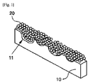
図1は、本発明に係る金属フィルタの構成を示した例示図であって、本発明は、船舶の排ガス内に含まれる窒素酸化物を除去する船舶排ガス浄化用の金属フィルタにおいて、前記金属フィルタ100は、粉末担体Ti-PILC(Pillared Clay)にバナジウム(V)、タングステン(W)及びアルミナゾル(Aluminasol)が担持された低温活性触媒20が、凹凸11を備えた金属基板10上にコーティングされている。
FIG. 1 is an exemplary diagram showing a configuration of a metal filter according to the present invention. The present invention relates to a metal filter for purifying a ship exhaust gas that removes nitrogen oxides contained in the exhaust gas of the ship. 100, a low-temperature
上記低温活性触媒20は、排ガス内に含まれる窒素酸化物除去用の低温活性触媒であって、粉末担体Ti-PILC(Pillared Clay)に、Ti-PILCの100重量部を基準として、バナジウム(V)前駆体の1〜10重量部、タングステン(W)前駆体の1〜5重量部、アルミナゾル(Aluminasol)の5〜20重量部を含むようになっている。
The low-temperature
また、上記低温活性触媒は、Ti-PILCの100重量部に対し、セリウム(Ce)前駆体の1〜5重量部、二酸化チタン(TiO2)前駆体の5〜20重量部、鉄(Fe)前駆体の1〜6重量部、二酸化硫黄(SO2)前駆体の1〜5重量部をさらに含んで構成することができる。 The low-temperature active catalyst is 1 to 5 parts by weight of a cerium (Ce) precursor, 5 to 20 parts by weight of a titanium dioxide (TiO 2 ) precursor, and iron (Fe) with respect to 100 parts by weight of Ti-PILC. It may further comprise 1 to 6 parts by weight of the precursor and 1 to 5 parts by weight of the sulfur dioxide (SO 2 ) precursor.
上記V、W、Ce、Fe、SO2は、低温活性触媒を活性化させることができる助触媒であって、押出低温活性触媒に比べて、相対的に低温で酸化/還元反応を活発に誘導することができる特徴を有する。 The above V, W, Ce, Fe, and SO 2 are co-catalysts that can activate the low-temperature active catalyst, and actively induce oxidation / reduction reactions at relatively low temperatures compared to the extrusion low-temperature active catalyst. It has the characteristics that can be done.
また、上記Ce、Fe、SO2は、硫黄(sulfur)に対する耐性を強化するだけでなく、V、W及びPILCの構造を安定化することができるので、安定性と耐久性の面において低温活性触媒の性能を確保することができる。 In addition, Ce, Fe, and SO 2 not only enhance resistance to sulfur, but also stabilize the structure of V, W, and PILC, so they are low temperature active in terms of stability and durability. The performance of the catalyst can be ensured.
上記助触媒(promoter)は、化学反応において触媒の活性を高めるために、固体の低温活性触媒に添加する物質であって、助触媒自体は、触媒の役割ができないが、一部の助触媒は、触媒の活性成分と相互作用し、活性固体成分の電子構造または結晶構造を変化させることにより、触媒作用を受ける物質に及ぼす化学的な効果を変化させることができる。 The promoter is a substance added to a solid low-temperature active catalyst in order to increase the activity of the catalyst in a chemical reaction, and the promoter itself cannot function as a catalyst. By interacting with the active component of the catalyst and changing the electronic structure or crystal structure of the active solid component, the chemical effect on the catalyzed substance can be changed.
また、助触媒の金属成分が過剰に使用されると、PILC担体上に均等に分散されるよりは、凝集や重なり現象によって、むしろ金属の活性面を浸漬することになり、パフォーマンスが低下することがあり、比率の範囲以下で過小に使用されると、分散度が低くなり、パフォーマンスが低下し、特定の混合比率によって添加される場合には、優れた活性特性を備えることになる。 Also, if the metal component of the cocatalyst is used in excess, the active surface of the metal will be immersed rather than being evenly dispersed on the PILC support, rather than agglomeration or overlap phenomenon, resulting in reduced performance. If it is used too little below the range of the ratio, the degree of dispersion will be low, the performance will be reduced, and when added at a specific mixing ratio, it will have excellent active properties.
上記アルミナゾル(Aluminasol)は、アルミナ(Alumina)単一成分の寝床型構造を有するゾル(sol)で構成される。 The above-mentioned alumina sol (Aluminasol) is composed of a sol having a bed type structure of alumina (Alumina) single component.
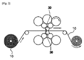
上記金属基板は、金属フィルタを形成するためのものであって、その材質は特に限定されるものではなく、表面に複数の凹凸を有する。すなわち、上記金属基板は、図2及び図3に示すように、ショットブラスト加工により表面に凹凸が形成されたローラ30により、表面に複数の凹凸が形成されており、上記金属基板上に形成された凹凸は、低温活性触媒との接触面積を増大させ、低温活性触媒の付着力を向上させる機能を有する。
The metal substrate is for forming a metal filter, and the material thereof is not particularly limited, and has a plurality of irregularities on the surface. That is, as shown in FIGS. 2 and 3, the metal substrate has a plurality of irregularities formed on the surface by a
すなわち、上記金属基板10の表面には、低温活性触媒の単位面積当たりのコーティング面積を平板に比べてより拡大させるための凹凸が形成されており、このように、凹凸が形成された金属基板10上に低温活性触媒20が塗布されると、金属基板10上への付着が行われる低温活性触媒20の端部が、平板型の金属母材に付着される場合に比べて、より小さい角度を有し、同じ質量であってもより拡大された領域にわたって接触がなされるようになる。
That is, the surface of the
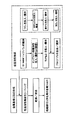
図4は、本発明に係る金属フィルターの製造工程を示したブロック例図図であって、上記のように構成される本発明の金属フィルターの製造工程は、金属基板に凹凸を成形する凹凸成形ステップと、凹凸を備えた金属基板をスラリー状態の低温活性触媒溶液に浸すか、機器から金属基板上に塗布することによって、低温活性触媒をコーティングするコーティングステップを含むようになっている。 FIG. 4 is a block diagram showing a manufacturing process of the metal filter according to the present invention, and the manufacturing process of the metal filter of the present invention configured as described above is a concavo-convex forming for forming a concavo-convex shape on a metal substrate. And a coating step of coating the low-temperature active catalyst by immersing the metal substrate with irregularities in a slurry-state low-temperature active catalyst solution or applying the metal substrate on the metal substrate from an apparatus.
また、上記低温活性触媒は、蒸留水(DI water)とバナジウム前駆体(V precursor)を攪拌する第1ステップ;第1ステップの後、pH2〜3に調整しながら、タングステン(W)前駆体を投入して攪拌する第2ステップ;第2ステップの後、Ti-PILCを投入して攪拌する第3ステップ;第3ステップの後、アルミナゾル(aluminasol)を添加して攪拌する第4ステップを含む工程によりスラリー状態で形成される。 The low-temperature active catalyst is a first step of stirring distilled water (DI water) and vanadium precursor (V precursor); after the first step, the tungsten (W) precursor is adjusted while adjusting the pH to 2-3. 2nd step of adding and stirring; 3rd step of adding and stirring Ti-PILC after 2nd step; 4th step of adding alumina sol (aluminasol) and stirring after 3rd step Is formed in a slurry state.
上記Ti-PILCは、韓国特許10-0415434に開示されたTi-PILCを使用するか、PILC (Pillared Clay)にTiをイオン交換法により置換して形成された公知のものを使用するので、これに対する説明は省略する。本発明におけるTi-PILCは、韓国特許10-0415434に開示されたTi-PILCを使用することが望ましい。 As the Ti-PILC, a Ti-PILC disclosed in Korean Patent 10-0415434 is used, or a known one formed by replacing PILC (Pillared Clay) with Ti by an ion exchange method is used. The description for is omitted. As the Ti-PILC in the present invention, it is desirable to use the Ti-PILC disclosed in Korean Patent 10-0415434.
また、上記低温活性触媒は、上記第3ステップの後と第4ステップの前に、酸化チタン(TiO2)を添加して攪拌する第3aステップと、上記第3aステップの後、セリウム(Ce)の前駆体、鉄の前駆体(Fe precursor)、SO2precursorから選択された1つ以上を追加的に添加して攪拌する第3bステップをさらに含む。 Further, the low-temperature active catalyst includes a 3a step of adding and stirring titanium oxide (TiO 2 ) after the third step and before the fourth step, and cerium (Ce) after the third a step. The method further includes a third step of adding and stirring at least one selected from the group consisting of a precursor, an iron precursor, and an SO 2 precursor.
すなわち、上記第3bステップは、一例として、第3aステップにおける攪拌物とセリウムの前駆体(Ce precursor)を攪拌する第3b-1ステップと、上記第3aステップにおける撹拌物、セリウムの前駆体、鉄の前駆体(Fe precursor)を攪拌する第3b-2ステップと、上記第3aステップにおける撹拌物、セリウムの前駆体、鉄の前駆体、SO2precursorを攪拌する第3b-3ステップをさらに含むことができる。 That is, the 3b step includes, as an example, the 3b-1 step of stirring the stirring material and cerium precursor (Ce precursor) in the 3a step, the stirring material, cerium precursor, iron in the 3a step. 3b-2 step of stirring the precursor (Fe precursor), and 3b-3 step of stirring the stirring material, cerium precursor, iron precursor, SO 2 precursor in step 3a above Can do.
上記のような本発明は、第1ステップが約10〜15min、第2ステップが10〜30min、第3ステップが1〜2hrs、第3aステップが1〜2hrs、第3bステップが30〜50min、望ましくは、30min、第4ステップが約25〜35minの間に持続的に行われる。 In the present invention as described above, the first step is about 10-15 min, the second step is 10-30 min, the third step is 1-2 hrs, the 3a step is 1-2 hrs, the 3b step is 30-50 min, preferably For 30 min and the fourth step is performed continuously for about 25 to 35 min.
上記のような低温活性触媒の製造は、50〜80℃の温度環境で行われ、Ti-PILC:蒸留水(DI water-イオンのない純粋な水)は、3〜5:6〜8の重量比を有する。例えば、Ti-PILC 30〜50g、DI water 60〜80mlを有する。 The production of the low-temperature active catalyst as described above is performed in a temperature environment of 50 to 80 ° C., and Ti-PILC: distilled water (DI water-pure water without ions) has a weight of 3 to 5: 6 to 8 Have a ratio. For example, it has Ti-PILC 30-50 g and DI water 60-80 ml.
また、低温活性触媒の製造時に各ステップで添加されるバナジウム前駆体(V precursor)、タングステン前駆体、鉄の前駆体、二酸化硫黄の前駆体、セリウム前駆体、二酸化チタンは、Ti-PILCの100重量部に対し、バナジウム(V)の1〜10重量部、タングステン(W)の1〜5重量部、二酸化チタン(TiO2)の5〜20重量部、鉄(Fe)の1〜6重量部、セリウムの1〜5重量部、二酸化硫黄(SO2)の1〜5重量部を含んでいる。 In addition, vanadium precursor (V precursor), tungsten precursor, iron precursor, sulfur dioxide precursor, cerium precursor, titanium dioxide, which are added at each step during the production of the low-temperature active catalyst, are Ti-PILC 100 1 to 10 parts by weight of vanadium (V), 1 to 5 parts by weight of tungsten (W), 5 to 20 parts by weight of titanium dioxide (TiO 2 ), 1 to 6 parts by weight of iron (Fe) with respect to parts by weight 1-5 parts by weight of cerium and 1-5 parts by weight of sulfur dioxide (SO 2 ).
上記バナジウム前駆体とタングステン前駆体は、特に制限されるものではなく、一例として、メタバナジウム酸アンモニウム(NH4VO3)または三塩化酸化バナジウム(VOCl3)等のようなバナジウム前駆体を用い、タングステン前駆体としては、アンモニウムタングステート((NH4)10H2(W2O7)6)を用いることができる。また、上記の各前駆体は、硝酸塩等のような公知の金属前駆体を用いるので、これについての詳細な説明は省略する。 The vanadium precursor and the tungsten precursor are not particularly limited. As an example, a vanadium precursor such as ammonium metavanadate (NH 4 VO 3 ) or vanadium trichloride (VOCl 3 ) is used. As the tungsten precursor, ammonium tungstate ((NH 4 ) 10 H 2 (W 2 O 7 ) 6 ) can be used. Moreover, since each said precursor uses well-known metal precursors, such as nitrate, the detailed description about this is abbreviate | omitted.
以下、本発明を実施例に基づいて説明すると、次の通りである。 Hereinafter, the present invention will be described based on examples.
<第1実施形態>
蒸留水(DI water)とバナジウム前駆体(V precursor)を30分間攪拌する第1ステップと、第1ステップの後、Ph2〜3に調整しながら、タングステン(W)前駆体を投入して30分間攪拌する第2ステップと、第2ステップの後、Ti-PILCを投入して2時間攪拌する第3ステップと、第3ステップの後、酸化チタン(TiO2)を添加して2時間攪拌する第3aステップと、前記第3aステップの後、セリウム(Ce)前駆体を添加して30分間攪拌する第3bステップと、第3bステップの後、アルミナゾル(aluminasol)を添加して30分間攪拌する第4ステップを順次に経て、PILC担体Ti-PILC、前記Ti-PILCの100重量部に対し、Vの3重量部、Wの3重量部、TiO2の5重量部、Ceの2重量部、アルミナゾル(Aluminasol)の8重量部を含むスラリー状態の低温活性触媒を製造した。
<First Embodiment>
1st step of stirring distilled water (DI water) and vanadium precursor (V precursor) for 30 minutes, and after adding the tungsten (W) precursor for 30 minutes while adjusting to Ph2-3 after the first step 2nd step to stir, 3rd step to stir 2 hours after adding Ti-PILC after 2nd step, and 2nd step to stir 2 hours after adding 3rd step and adding titanium oxide (TiO 2 ) Step 3a, Step 3b after adding the cerium (Ce) precursor after Step 3a, and Step 3b after adding Step 3b, Step 3b, adding alumina sol and stirring for 30 minutes Through successive steps, PILC support Ti-PILC, 100 parts by weight of Ti-PILC, 3 parts by weight of V, 3 parts by weight of W, 5 parts by weight of TiO 2 , 2 parts by weight of Ce, alumina sol ( A low temperature active catalyst in a slurry state containing 8 parts by weight of Aluminasol was prepared.
このとき、前記Ti-PILCと、DI(De-ionized)water(イオンのない純粋な水)は、4:7の重量比を有するようにした。 At this time, the Ti-PILC and DI (De-ionized) water (pure water without ions) had a weight ratio of 4: 7.
<第2実施形態>
凹凸が形成された金属基板(ステンレス材)に、第1実施形態に係るスラリー状態の低温活性触媒を塗布・コーティングし、これを乾燥焼成させることにより、低温活性触媒がコーティングされた金属フィルタを形成し、これに対して250〜300℃の温度範囲において窒素酸化物の低減効率を実験した。その結果を以下の表2に示した。
<Second Embodiment>
A metal filter coated with a low-temperature active catalyst is formed by applying and coating the slurry-like low-temperature active catalyst according to the first embodiment on a metal substrate (stainless steel) on which irregularities are formed, and drying and firing this. On the other hand, the nitrogen oxide reduction efficiency was tested in the temperature range of 250 to 300 ° C. The results are shown in Table 2 below.
上記の表2に示すように、250℃以上において80%以上の窒素酸化物の低減効率を実現することが分かり、295℃以上においては、90%の窒素酸化物の低減効率を実現することが分かった。
As shown in Table 2 above, it can be seen that a nitrogen oxide reduction efficiency of 80% or more is realized at 250 ° C or higher, and a nitrogen oxide reduction efficiency of 90% is realized at 295 ° C or higher. I understood.
<第3実施形態>
凹凸が形成されたセラミック基板(Ceramic Substrate)(例えば、Cordierite substrate)に、第1実施形態に係るスラリー状態の低温活性触媒を塗布・コーティングし、これを乾燥焼成させることにより、低温活性触媒がコーティングされたセラミック金属フィルター(cordierite材質のハニカム形状の基板)を形成し、これに対して250〜300℃の温度範囲において窒素酸化物の低減効率を実験した。その結果を以下の表3に示した。この時の実験条件は、第2実施形態における実験条件と同様である。
<Third embodiment>
The low-temperature active catalyst is coated by coating and coating the slurry-like low-temperature active catalyst according to the first embodiment on a ceramic substrate (for example, Cordierite substrate) on which irregularities are formed, and drying and firing this. A ceramic metal filter (a honeycomb-shaped substrate made of cordierite material) was formed, and a nitrogen oxide reduction efficiency was tested in a temperature range of 250 to 300 ° C. The results are shown in Table 3 below. The experimental conditions at this time are the same as the experimental conditions in the second embodiment.
<第4実施形態>
蒸留水(DI water)とバナジウム前駆体(V precursor)を30分間攪拌する第1ステップと、第1ステップの後、pH2〜3に調整しながら、タングステン(W)前駆体を投入して30分間攪拌する第2ステップと、第2ステップの後、Ti-PILCを投入して2時間攪拌する第3ステップと、第3ステップの後、酸化チタン(TiO2)を添加して2時間攪拌する第3aステップと、前記第3aステップの後、セリウム(Ce)前駆体を添加して30分間攪拌する第3b-1ステップと、第3b-1ステップの後、鉄の前駆体を投入して30分間攪拌する第3b-2ステップと、第3b-2ステップの後、アルミナゾル(aluminasol)を添加して30分間攪拌する第4ステップを順次に経て、PILC担体Ti-PILC、上記Ti-PILC 100重量部に対し、Vの3重量部、Wの3重量部、TiO2の5重量部、Ceの2重量部、Feの3重量部、アルミナゾル(Aluminasol)の15重量部を含むスラリー状態の低温活性触媒を製造した。
<Fourth embodiment>
The first step of stirring distilled water (DI water) and vanadium precursor (V precursor) for 30 minutes, and after the first step, adjusting the pH to 2-3, adding tungsten (W) precursor for 30 minutes 2nd step to stir, 3rd step to stir 2 hours after adding Ti-PILC after 2nd step, and 3a after adding 3rd step and adding titanium oxide (TiO2) after 3rd step Step 3b-1 after adding the cerium (Ce) precursor after the step 3a and stirring for 30 minutes, and after step 3b-1 adding the iron precursor and stirring for 30 minutes 3b-2 step, and after the 3b-2 step, after adding 4 steps of adding alumina sol (aluminasol) and stirring for 30 minutes, PILC carrier Ti-PILC, and 100 parts by weight of Ti-PILC above In contrast, 3 parts by weight of V, 3 parts by weight of W, 5 parts by weight of TiO 2 , 2 parts by weight of Ce, 3 parts by weight of Fe, Aluminasol A low temperature active catalyst in a slurry state containing 15 parts by weight was produced.
このとき、前記Ti-PILCと、DI(De-ionized)water(イオンのない純粋な水)は、4:7の重量比を有するようにした。 At this time, the Ti-PILC and DI (De-ionized) water (pure water without ions) had a weight ratio of 4: 7.
<第5実施形態>
凹凸が形成された金属基板(ステインス材)に、第4実施形態に係るスラリー状態の低温活性触媒を塗布・コーティングし、これを乾燥焼成させることにより、低温活性触媒がコーティングされた金属フィルタを形成し、これに対して250〜300℃の温度範囲において窒素酸化物の低減効率を実験した。その結果は、以下の表4に示した。この際、実験条件は第2実施形態の実験条件と同様である。
<Fifth embodiment>
A metal filter coated with a low-temperature active catalyst is formed by applying and coating the slurry-like low-temperature active catalyst according to the fourth embodiment on a metal substrate (stain material) on which irregularities are formed, and drying and firing this. On the other hand, the nitrogen oxide reduction efficiency was tested in the temperature range of 250 to 300 ° C. The results are shown in Table 4 below. At this time, the experimental conditions are the same as the experimental conditions of the second embodiment.
<第6実施形態>
凹凸が形成されたセラミック基板に、第4実施形態に係るスラリー状態の低温活性触媒を塗布・コーティングし、これを乾燥焼成させることにより、低温活性触媒がコーティングされたセラミック金属フィルタを形成し、これに対して250〜300℃の温度範囲において窒素酸化物の低減効率を実験した。その結果を、以下の表5に示した。このとき、実験条件は第2実施形態の実験条件と同様である。
<Sixth Embodiment>
A ceramic substrate filter coated with a low-temperature active catalyst is formed by applying and coating the slurry-like low-temperature active catalyst according to the fourth embodiment on a ceramic substrate with irregularities formed thereon, followed by drying and firing. On the other hand, the reduction efficiency of nitrogen oxide was experimented in the temperature range of 250-300 ° C. The results are shown in Table 5 below. At this time, the experimental conditions are the same as the experimental conditions of the second embodiment.
<第7実施形態>
蒸留水(DI water)とバナジウム前駆体(V precursor)を30分間攪拌する第1ステップと、第1ステップの後、pH2〜3に調整しながら、タングステン(W)前駆体を投入して30分間攪拌する第2ステップと、第2ステップの後、Ti-PILCを投入して2時間攪拌する第3ステップと、第3ステップの後、酸化チタン(TiO2)を添加して2時間攪拌する第3aステップと、前記第3aステップの後、セリウム(Ce)前駆体を添加して30分間攪拌する第3b-1ステップと、第3b-1ステップの後、鉄の前駆体を投入して30分間攪拌する第3b-2ステップと、第3b-2ステップの後、SO2 precursorを投入して30分間攪拌する第3b-3ステップと、第3b-3ステップの後、アルミナゾル(aluminasol)を添加して30分間攪拌する第4ステップを順次に経て、PILC担体Ti-PILC、上記Ti-PILCの100重量部に対し、V3の重量部、Wの3重量部、TiO2の5重量部、Ceの2重量部、Feの3重量部、SO2の2重量部、アルミナゾル(Aluminasol)の15重量部を含むスラリー状態の低温活性触媒を製造した。
<Seventh embodiment>
The first step of stirring distilled water (DI water) and vanadium precursor (V precursor) for 30 minutes, and after the first step, adjusting the pH to 2-3, adding tungsten (W) precursor for 30 minutes 2nd step to stir, 3rd step to stir 2 hours after adding Ti-PILC after 2nd step, and 2nd step to stir 2 hours after adding 3rd step and adding titanium oxide (TiO 2 ) Step 3a, Step 3b-1 after adding the cerium (Ce) precursor after Step 3a, and stirring for 30 minutes; Step 3b-1; 3b-2 step to stir, 3b-2 step, 3b-3 step to add SO2 precursor and stir for 30 minutes, and 3b-3 step, then add alumina sol (aluminasol) Through the fourth step of stirring for 30 minutes, PILC carrier Ti-PILC, 100 parts by weight of Ti-PILC, 3 parts by weight of V3, 3 parts of W The amount unit, 5 parts by weight of TiO 2, 2 parts by weight of Ce, 3 parts by weight of Fe, 2 parts by weight of SO 2, to produce a low temperature active catalyst in a slurry state containing 15 parts by weight of alumina sol (Aluminasol).
このとき、前記Ti-PILCとDI(De-ionized)water(イオンのない純粋な水)とは、4:7の重量比を有するようにした。 At this time, the Ti-PILC and DI (De-ionized) water (pure water without ions) had a weight ratio of 4: 7.
<第8実施形態>
凹凸が形成された金属基板(ステンレス材)に、第7実施形態に係るスラリー状態の低温活性触媒を塗布・コーティングし、これを乾燥焼成させることにより、低温活性触媒がコーティングされた金属フィルタを形成し、これに対し、250〜300℃の温度範囲において窒素酸化物の低減効率を実験した。その結果を、以下の表6に示した。この際、実験条件は第2実施形態の実験条件と同様である。
<Eighth embodiment>
A metal filter coated with a low-temperature active catalyst is formed by applying and coating a slurry-like low-temperature active catalyst according to the seventh embodiment on a metal substrate (stainless steel) on which irregularities are formed, and drying and firing this. On the other hand, nitrogen oxide reduction efficiency was tested in the temperature range of 250 to 300 ° C. The results are shown in Table 6 below. At this time, the experimental conditions are the same as the experimental conditions of the second embodiment.
<第9実施形態>
凹凸が形成されたセラミック基板に、第7実施形態に係るスラリー状態の低温活性触媒を塗布・コーティングし、これを乾燥焼成させることにより、低温活性触媒がコーティングされたセラミック金属フィルタを形成し、これに対して250〜300℃の温度範囲において窒素酸化物の低減効率を実験した。その結果を、以下の表7に示した。この際、実験条件は第2実施形態の実験条件と同様である。
<Ninth embodiment>
A ceramic substrate filter coated with a low-temperature active catalyst is formed by applying and coating the slurry-like low-temperature active catalyst according to the seventh embodiment on a ceramic substrate having irregularities formed thereon, followed by drying and firing. On the other hand, the reduction efficiency of nitrogen oxide was experimented in the temperature range of 250-300 ° C. The results are shown in Table 7 below. At this time, the experimental conditions are the same as the experimental conditions of the second embodiment.
上記表2乃至表7によれば、本発明に係る船舶排ガス金属フィルター用の低温活性触媒は、第1実施形態<第4実施形態<第7実施形態の順に窒素酸化物の除去効率が優れていることが分かる。 According to Tables 2 to 7, the low-temperature active catalyst for a ship exhaust gas metal filter according to the present invention is excellent in nitrogen oxide removal efficiency in the order of the first embodiment <fourth embodiment <seventh embodiment. I understand that.
また、一般的に金属基板を用いる場合には、セラミック基板を用いる場合に比べて、窒素酸化物の除去効率が低いことが知られているが、本発明は、凹凸面を有する金属基板10を利用することにより、セラミック基板と同程度の窒素酸化物除去効率を実現することが分かった。 Further, in general, when using a metal substrate, it is known that nitrogen oxide removal efficiency is lower than when using a ceramic substrate. It has been found that the use of this material achieves the same nitrogen oxide removal efficiency as that of the ceramic substrate.
また、実際の船舶の場合、SV(space velocity)は、5,000〜10,000h-1程度であるため、実際の船舶運行時には、上記第2実施形態,3,5,6,8,9の実験条件であるSV 20000h-1に比べて、反応ガスと低温活性触媒サイトとの間の反応時間が増加し、かつ、反応することのできるガスも確率的に増加するので、表2乃至表7から分かるパフォーマンスよりも窒素酸化物の低減効率はさらに向上すると考えることができる。 Further, in the case of an actual ship, the SV (space velocity) is about 5,000 to 10,000 h −1 , so the experimental conditions of the second embodiment, 3, 5, 6, 8, 9 are used during actual ship operation. Compared to SV 20000h -1 , the reaction time between the reaction gas and the low-temperature active catalyst site is increased, and the gas that can be reacted is also increased stochastically, so it can be seen from Tables 2 to 7. It can be considered that the reduction efficiency of nitrogen oxides is further improved than the performance.
<第10実施形態>
上記の第8実施形態に係る金属フィルターおよび第9実施形態に係るセラミック金属フィルターと、既存の船舶用の押出触媒フィルターに対する触媒付着性を評価し、その結果を表8に示した。
<Tenth embodiment>
Catalyst adhesion to the metal filter according to the eighth embodiment and the ceramic metal filter according to the ninth embodiment and the existing extruded catalyst filter for ships was evaluated, and the results are shown in Table 8.
触媒付着性評価は、それぞれの試験片を、水で満たされたビーカーに個別に浸し、それぞれのビーカーを超音波洗浄装置に入れ、40MHzで3minの間に超音波を印加し、その後、各試験片を24hrsの間に十分乾燥した後の重量を測定して、触媒の損失量(付着性)を計算した。 For catalyst adhesion evaluation, each test piece was individually immersed in a beaker filled with water, each beaker was placed in an ultrasonic cleaning device, ultrasonic waves were applied at 40 MHz for 3 min, and then each test was performed. After the piece was sufficiently dried for 24 hrs, the weight was measured, and the amount of catalyst loss (adhesion) was calculated.
上記の表8に示すように、従来の押出触媒フィルタ<本発明に係るセラミック金属フィルタ<本発明に係る金属フィルタの順に付着性が優れていることが分かる。 As shown in Table 8 above, it can be seen that the adhesion is excellent in the following order: conventional extruded catalyst filter <ceramic metal filter according to the present invention <metal filter according to the present invention.
上記のような優れた付着性を実現するにあたっては、Alumina単一成分の寝床型構造を有するゾル(sol)形態の上記Aluminasolの採用と、その適正な組成比や凹凸構造を有するなど、主に上記金属基板の表面特性に基づいた。 In realizing the excellent adhesion as described above, the adoption of the above-mentioned Aluminasol in the form of a sol having a single-layer bed structure of Alumina, and its proper composition ratio and uneven structure are mainly used. Based on the surface properties of the metal substrate.
本発明は、上述した特定の好ましい実施形態に限定されるものでなく、特許請求の範囲にて請求する本発明の要旨を逸脱することなく、当該発明の属する技術分野における通常の知識を有する者であれば誰でも多様な変形実施が可能なのはもちろん、そのような変更は、特許請求の範囲に記載した範囲内のものである。 The present invention is not limited to the specific preferred embodiments described above, and has ordinary knowledge in the technical field to which the invention belongs without departing from the spirit of the invention claimed in the claims. Anyone can make various modifications, and such changes are within the scope of the claims.
10 金属基板
11 凹凸
20 低温活性触媒
100 金属フィールター
10
Claims (9)
前記金属フィルターは、
粉末担体Ti-PILC(Pillared Clay)にバナジウム(V)、タングステン(W)、及びアルミナゾル(Aluminasol)が担持された低温活性触媒が、凹凸を備えている金属基板上にコーティングされていることを特徴とする船舶排ガス浄化用の金属フィルター。 In the metal filter for ship exhaust gas purification that removes nitrogen oxide contained in the exhaust gas of the ship,
The metal filter is
A low-temperature active catalyst in which vanadium (V), tungsten (W), and alumina sol (Aluminasol) are supported on a powder carrier Ti-PILC (Pillared Clay) is coated on a metal substrate with irregularities. Metal filter for purifying ship exhaust gas.
金属基板に凹凸を成形する凹凸成形ステップと、
凹凸を備えた金属基板をスラリー状態の低温活性触媒の溶液に浸すか、または、機器から金属基板上に塗布することにより、低温活性触媒をコーティングするコーティングステップを含むことを特徴とする船舶排ガス浄化用の金属フィルターの製造方法。 In the manufacturing method of the metal filter for ship exhaust gas purification that removes nitrogen oxides contained in the exhaust gas of the ship,
An uneven forming step for forming unevenness on a metal substrate;
Vessel exhaust gas purification characterized by including a coating step of coating a low temperature active catalyst by immersing a metal substrate with irregularities in a solution of a low temperature active catalyst in a slurry state or by applying it on a metal substrate from a device Method for manufacturing metal filters.
蒸留水(DI water)とバナジウム前駆体(V precursor)を攪拌する第1ステップと、
第1ステップの後、pH2〜3に調整しながら、タングステン(W)前駆体を投入して攪拌する第2ステップと、
第2ステップの後、Ti-PILCを投入して攪拌する第3ステップと、
第3ステップの後、アルミナゾル(aluminasol)を添加して攪拌する第4ステップを含めてスラリー状態で形成されたことを特徴とする請求項4に記載の船舶排ガス浄化用の金属フィルターの製造方法。 The low temperature active catalyst is:
A first step of stirring distilled water (DI water) and vanadium precursor (V precursor);
After the first step, while adjusting the pH to 2-3, a second step of adding and stirring the tungsten (W) precursor,
After the second step, a third step of adding and stirring Ti-PILC,
5. The method for producing a metal filter for purifying ship exhaust gas according to claim 4, wherein the metal filter is formed in a slurry state including a fourth step of adding and stirring alumina sol after the third step.
前記第3aステップの後、セリウム(Ce)の前駆体、鉄の前駆体(Fe precursor)及びSO2precursorから選択された1つ以上を追加的に添加して攪拌する第3bステップをさらに含むことを特徴とする請求項5に記載の船舶排ガス浄化用の金属フィルターの製造方法。 The low temperature active catalyst, after the third step and before the fourth step, a third a step of adding and stirring titanium oxide (TiO 2 ),
After the step 3a, the method further includes a step 3b in which one or more selected from a cerium (Ce) precursor, an iron precursor (Fe precursor), and a SO 2 precursor are added and stirred. The method for producing a metal filter for purifying ship exhaust gas according to claim 5.
第3aステップにおける撹拌物とセリウムの前駆体(Ce precursor)を攪拌する第3b-1ステップと、
前記第3aステップにおける撹拌物とセリウムの前駆体および鉄の前駆体(Fe precursor)を攪拌する第3b-2ステップと、
前記第3aステップにおける撹拌物とセリウムの前駆体、鉄の前駆体およびSO2 precursorを攪拌する第3b-3ステップからなることを特徴とする請求項8に記載の船舶排ガス浄化用の金属フィルターの製造方法。 The step 3b includes
Step 3b-1 of stirring the agitated material and cerium precursor in step 3a; and
Step 3b-2 of stirring the agitated material, the cerium precursor and the iron precursor (Fe precursor) in Step 3a,
Precursor of the stirring thereof and cerium in said first 3a step, the metal filter for ships purification of exhaust gas according to claim 8, characterized in that it consists of the 3b-3 step of agitating the precursor and SO 2 precursor iron Production method.
Applications Claiming Priority (3)
| Application Number | Priority Date | Filing Date | Title |
|---|---|---|---|
| KR10-2012-0031616 | 2012-03-28 | ||
| KR1020120031616A KR101907147B1 (en) | 2012-03-28 | 2012-03-28 | Metallic filter for exhaust gas of marine |
| PCT/KR2013/002383 WO2013147465A1 (en) | 2012-03-28 | 2013-03-22 | Metal filter for purifying exhaust gas from ship, and preparation method thereof |
Publications (2)
| Publication Number | Publication Date |
|---|---|
| JP2014515311A true JP2014515311A (en) | 2014-06-30 |
| JP2014515311A5 JP2014515311A5 (en) | 2015-08-06 |
Family
ID=49260653
Family Applications (1)
| Application Number | Title | Priority Date | Filing Date |
|---|---|---|---|
| JP2014513464A Pending JP2014515311A (en) | 2012-03-28 | 2013-03-22 | Metal filter for purification of ship exhaust gas and method for producing the same |
Country Status (7)
| Country | Link |
|---|---|
| US (1) | US9371765B2 (en) |
| JP (1) | JP2014515311A (en) |
| KR (1) | KR101907147B1 (en) |
| CN (1) | CN103648617B (en) |
| DK (1) | DK178798B1 (en) |
| FI (1) | FI127851B (en) |
| WO (1) | WO2013147465A1 (en) |
Cited By (4)
| Publication number | Priority date | Publication date | Assignee | Title |
|---|---|---|---|---|
| JP2015066473A (en) * | 2013-09-26 | 2015-04-13 | 株式会社日本触媒 | Catalyst for treating marine exhaust gas and exhaust gas treatment method |
| CN106040287A (en) * | 2015-04-13 | 2016-10-26 | 丰田自动车株式会社 | Exhaust gas purification catalyst |
| JP2018527168A (en) * | 2015-07-15 | 2018-09-20 | ヒュンダイ ヘビー インダストリーズ カンパニー リミテッドHyundai Heavy Industries Co., Ltd. | SCR catalyst for removing nitrogen oxides and method for producing the same |
| CN108554410A (en) * | 2018-05-03 | 2018-09-21 | 东华大学 | A kind of Fe/Ti-PILC catalyst, preparation method and application |
Families Citing this family (3)
| Publication number | Priority date | Publication date | Assignee | Title |
|---|---|---|---|---|
| DE102014201263A1 (en) | 2014-01-23 | 2015-07-23 | Johnson Matthey Catalysts (Germany) Gmbh | catalyst |
| KR20180030712A (en) * | 2015-08-14 | 2018-03-23 | 바스프 코포레이션 | Ion-exchanged synthetic phyllosilicates as SCR catalysts |
| CN114433115B (en) * | 2020-10-16 | 2024-01-30 | 中国石油化工股份有限公司 | Coating slurry and preparation method and application thereof |
Citations (15)
| Publication number | Priority date | Publication date | Assignee | Title |
|---|---|---|---|---|
| JPS50128681A (en) * | 1974-03-29 | 1975-10-09 | ||
| JPS5242464A (en) * | 1975-10-01 | 1977-04-02 | Hitachi Ltd | Method of reducing and removing nox in exhaust gas |
| JPS54122690A (en) * | 1978-03-16 | 1979-09-22 | Hitachi Zosen Corp | Catalyst carrier |
| JPS5513127A (en) * | 1978-07-14 | 1980-01-30 | Mitsubishi Heavy Ind Ltd | Metal-based catalyst |
| JPS5697548A (en) * | 1980-01-09 | 1981-08-06 | Mitsubishi Heavy Ind Ltd | Preparation of catalyst containing metal as base material |
| JPS6388047A (en) * | 1987-08-28 | 1988-04-19 | Ngk Insulators Ltd | Preparation of catalyst for removing nitrogen oxide |
| JPS63147546A (en) * | 1986-07-29 | 1988-06-20 | Mitsubishi Petrochem Co Ltd | Method for removing nitrogen oxide in exhaust gas |
| JPH01168341A (en) * | 1987-11-27 | 1989-07-03 | Degussa Ag | Catalyst for selectively reducing nitrogen oxide using ammonia |
| JPH01288338A (en) * | 1988-05-16 | 1989-11-20 | Babcock Hitachi Kk | Catalyst for catalytic reduction of nitrogen oxides |
| JPH05154351A (en) * | 1991-12-11 | 1993-06-22 | Babcock Hitachi Kk | Plate type denitration catalyst and preparation of the same |
| JPH1099684A (en) * | 1996-09-04 | 1998-04-21 | Basf Ag | Catalyst composition for reduction of nox, its production and reducing method for nox in exhaust combustion gas containing oxygen |
| JP2001300309A (en) * | 2000-04-20 | 2001-10-30 | Hyundai Heavy Industries Co Ltd | Vanadium oxide catalyst in which titania for removing nitrogen oxides is impregnated in columnar bentnite |
| JP2006501064A (en) * | 2002-09-30 | 2006-01-12 | イーカーオー・ミネラルズ・ゲゼルシャフト・ミト・ベシュレンクテル・ハフツング | Process for producing catalyzed layered silicates |
| JP2007032400A (en) * | 2005-07-26 | 2007-02-08 | Mitsui Eng & Shipbuild Co Ltd | Method for processing particulate in diesel engine exhaust gas |
| JP2007529300A (en) * | 2004-03-17 | 2007-10-25 | ジーエム・グローバル・テクノロジー・オペレーションズ・インコーポレーテッド | Catalyst for improving the efficiency of NOx reduction in automobiles |
Family Cites Families (14)
| Publication number | Priority date | Publication date | Assignee | Title |
|---|---|---|---|---|
| GB1511841A (en) * | 1974-03-06 | 1978-05-24 | Johnson Matthey Co Ltd | Catalysis |
| US5225390A (en) * | 1988-02-23 | 1993-07-06 | Siemens Aktiengesellschaft | Catalyst for reducing nitrogen oxides |
| US5166122A (en) * | 1988-09-19 | 1992-11-24 | Babcock-Hitachi Kabushiki Kaisha | Process for producing a denitration catalyst |
| US6521559B1 (en) * | 1999-09-27 | 2003-02-18 | The Regents Of The University Of Michigan | Superior pillared clay catalysts for selective catalytic reduction of nitrogen oxides for power plant emission control |
| WO2001028665A1 (en) | 1999-10-15 | 2001-04-26 | Abb Lummus Global, Inc. | Conversion of nitrogen oxides in the presence of a catalyst supported of a mesh-like structure |
| US6475944B1 (en) * | 2000-03-27 | 2002-11-05 | Hyundai Heavy Industries Co., Ltd. | Vanadia catalyst impregnated on titania-pillared clay for the removal of nitrogen oxide |
| JP4246412B2 (en) * | 2001-07-05 | 2009-04-02 | 株式会社日本触媒 | Exhaust gas treatment catalyst and exhaust gas purification method using the same |
| DE10207986A1 (en) * | 2002-02-25 | 2003-09-04 | Daimler Chrysler Ag | Emission control system for an internal combustion engine |
| CN100560204C (en) * | 2003-12-24 | 2009-11-18 | 中国科学院生态环境研究中心 | Catalyst for purification of nitrogen oxides in the sulfur-bearing oxygen enrichment tail gas |
| KR100629574B1 (en) * | 2005-03-14 | 2006-09-27 | 현대중공업 주식회사 | Catalyst for nitrogen oxides reduction using activated carbon and method for preparing the same |
| US7712308B2 (en) * | 2005-11-08 | 2010-05-11 | Tenneco Automotive Operating Company Inc. | Selective catalyst reduction of nitrogen oxides with hydrogen |
| KR100969060B1 (en) * | 2007-12-11 | 2010-07-09 | 현대자동차주식회사 | Method for manufacturing metal filter using electrophoretic deposition |
| KR101100851B1 (en) * | 2009-10-29 | 2012-01-02 | 한국전력기술 주식회사 | An Exhaust Gas Denitrifing System having Reducer-mixing and Noise-diminution Structure |
| KR101276103B1 (en) * | 2011-01-19 | 2013-06-18 | 현대비앤지스틸 주식회사 | low temperature activity catalysts used in filter for exhaust gas of ship, preparing method thereof and filter for exhaust gas of ship |
-
2012
- 2012-03-28 KR KR1020120031616A patent/KR101907147B1/en active IP Right Grant
-
2013
- 2013-03-22 US US14/232,807 patent/US9371765B2/en active Active
- 2013-03-22 CN CN201380002045.6A patent/CN103648617B/en active Active
- 2013-03-22 JP JP2014513464A patent/JP2014515311A/en active Pending
- 2013-03-22 FI FI20145083A patent/FI127851B/en active IP Right Grant
- 2013-03-22 WO PCT/KR2013/002383 patent/WO2013147465A1/en active Application Filing
- 2013-03-22 DK DKPA201300648A patent/DK178798B1/en active
Patent Citations (15)
| Publication number | Priority date | Publication date | Assignee | Title |
|---|---|---|---|---|
| JPS50128681A (en) * | 1974-03-29 | 1975-10-09 | ||
| JPS5242464A (en) * | 1975-10-01 | 1977-04-02 | Hitachi Ltd | Method of reducing and removing nox in exhaust gas |
| JPS54122690A (en) * | 1978-03-16 | 1979-09-22 | Hitachi Zosen Corp | Catalyst carrier |
| JPS5513127A (en) * | 1978-07-14 | 1980-01-30 | Mitsubishi Heavy Ind Ltd | Metal-based catalyst |
| JPS5697548A (en) * | 1980-01-09 | 1981-08-06 | Mitsubishi Heavy Ind Ltd | Preparation of catalyst containing metal as base material |
| JPS63147546A (en) * | 1986-07-29 | 1988-06-20 | Mitsubishi Petrochem Co Ltd | Method for removing nitrogen oxide in exhaust gas |
| JPS6388047A (en) * | 1987-08-28 | 1988-04-19 | Ngk Insulators Ltd | Preparation of catalyst for removing nitrogen oxide |
| JPH01168341A (en) * | 1987-11-27 | 1989-07-03 | Degussa Ag | Catalyst for selectively reducing nitrogen oxide using ammonia |
| JPH01288338A (en) * | 1988-05-16 | 1989-11-20 | Babcock Hitachi Kk | Catalyst for catalytic reduction of nitrogen oxides |
| JPH05154351A (en) * | 1991-12-11 | 1993-06-22 | Babcock Hitachi Kk | Plate type denitration catalyst and preparation of the same |
| JPH1099684A (en) * | 1996-09-04 | 1998-04-21 | Basf Ag | Catalyst composition for reduction of nox, its production and reducing method for nox in exhaust combustion gas containing oxygen |
| JP2001300309A (en) * | 2000-04-20 | 2001-10-30 | Hyundai Heavy Industries Co Ltd | Vanadium oxide catalyst in which titania for removing nitrogen oxides is impregnated in columnar bentnite |
| JP2006501064A (en) * | 2002-09-30 | 2006-01-12 | イーカーオー・ミネラルズ・ゲゼルシャフト・ミト・ベシュレンクテル・ハフツング | Process for producing catalyzed layered silicates |
| JP2007529300A (en) * | 2004-03-17 | 2007-10-25 | ジーエム・グローバル・テクノロジー・オペレーションズ・インコーポレーテッド | Catalyst for improving the efficiency of NOx reduction in automobiles |
| JP2007032400A (en) * | 2005-07-26 | 2007-02-08 | Mitsui Eng & Shipbuild Co Ltd | Method for processing particulate in diesel engine exhaust gas |
Cited By (6)
| Publication number | Priority date | Publication date | Assignee | Title |
|---|---|---|---|---|
| JP2015066473A (en) * | 2013-09-26 | 2015-04-13 | 株式会社日本触媒 | Catalyst for treating marine exhaust gas and exhaust gas treatment method |
| CN106040287A (en) * | 2015-04-13 | 2016-10-26 | 丰田自动车株式会社 | Exhaust gas purification catalyst |
| JP2016198741A (en) * | 2015-04-13 | 2016-12-01 | トヨタ自動車株式会社 | Catalyst for exhaust purification |
| US9789474B2 (en) | 2015-04-13 | 2017-10-17 | Toyota Jidosha Kabushiki Kaisha | Exhaust gas purification catalyst |
| JP2018527168A (en) * | 2015-07-15 | 2018-09-20 | ヒュンダイ ヘビー インダストリーズ カンパニー リミテッドHyundai Heavy Industries Co., Ltd. | SCR catalyst for removing nitrogen oxides and method for producing the same |
| CN108554410A (en) * | 2018-05-03 | 2018-09-21 | 东华大学 | A kind of Fe/Ti-PILC catalyst, preparation method and application |
Also Published As
| Publication number | Publication date |
|---|---|
| KR20130109674A (en) | 2013-10-08 |
| KR101907147B1 (en) | 2018-10-12 |
| WO2013147465A1 (en) | 2013-10-03 |
| US20140170032A1 (en) | 2014-06-19 |
| FI127851B (en) | 2019-04-15 |
| DK201300648A (en) | 2013-11-15 |
| CN103648617A (en) | 2014-03-19 |
| US9371765B2 (en) | 2016-06-21 |
| DK178798B1 (en) | 2017-02-13 |
| CN103648617B (en) | 2016-05-04 |
| FI20145083A (en) | 2014-01-27 |
Similar Documents
| Publication | Publication Date | Title |
|---|---|---|
| JP2014515311A (en) | Metal filter for purification of ship exhaust gas and method for producing the same | |
| KR101798713B1 (en) | SCR Catalyst for Nitrogen Oxide Removal and Manufacturing method thereof | |
| JP2005177738A (en) | Multipart catalyst system for exhaust gas treatment element | |
| CN103769083B (en) | A kind of NO_x Reduction by Effective composite oxide catalysts and its preparation method and application | |
| JP2013091045A (en) | Exhaust gas treating method | |
| WO2014054607A1 (en) | Shipboard gas treatment apparatus | |
| JP3826167B2 (en) | Nitrogen oxide removal method using natural manganese ore | |
| JP5787901B2 (en) | NOx removal catalyst carrier, NOx removal catalyst and NOx removal device | |
| KR101717319B1 (en) | Nox reduction catalyst for exhaust gas of biomass combustion and nox reduction method | |
| JP4989545B2 (en) | Nitrogen oxide catalytic reduction catalyst | |
| KR20170126837A (en) | SCR Catalyst for Nitrogen Oxide Removal and Manufacturing Method Thereof | |
| JP2010142688A (en) | Catalyst for selective catalytic reduction of nitrogen oxide | |
| JP5178164B2 (en) | Exhaust gas purification catalyst | |
| EP1360006A1 (en) | A catalyst for selective catalytic reduction of nitrogen oxides and a method for preparing the same | |
| KR101276103B1 (en) | low temperature activity catalysts used in filter for exhaust gas of ship, preparing method thereof and filter for exhaust gas of ship | |
| JP6261260B2 (en) | Ship exhaust gas treatment catalyst and exhaust gas treatment method | |
| JP3495548B2 (en) | Reduction method of sulfur trioxide | |
| US20120124976A1 (en) | Apparatus for removing mixed nitrogen oxides, carbon monoxide, hydrocarbons and diesel particulate matter from diesel engine exhaust streams at temperatures at or below 280 degrees c | |
| JP4499511B2 (en) | Method for treating exhaust gas containing nitrogen oxides | |
| JP4948331B2 (en) | Ship exhaust gas treatment method | |
| JP4918241B2 (en) | Exhaust gas treatment catalyst, exhaust gas treatment method and exhaust gas treatment device | |
| JP2002102696A (en) | Denitration catalyst and processing method for exhaust gas using this | |
| JP2000093803A (en) | Catalyst for purification of exhaust gas and purification of exhaust gas | |
| JP2016064358A (en) | Marine exhaust gas treatment catalyst, and exhaust treatment method | |
| JP2004298760A (en) | Method for regenerating spent denitrification catalyst |
Legal Events
| Date | Code | Title | Description |
|---|---|---|---|
| A621 | Written request for application examination |
Free format text: JAPANESE INTERMEDIATE CODE: A621 Effective date: 20131129 |
|
| A977 | Report on retrieval |
Free format text: JAPANESE INTERMEDIATE CODE: A971007 Effective date: 20150204 |
|
| A131 | Notification of reasons for refusal |
Free format text: JAPANESE INTERMEDIATE CODE: A131 Effective date: 20150210 |
|
| A601 | Written request for extension of time |
Free format text: JAPANESE INTERMEDIATE CODE: A601 Effective date: 20150507 |
|
| A521 | Written amendment |
Free format text: JAPANESE INTERMEDIATE CODE: A523 Effective date: 20150609 |
|
| A524 | Written submission of copy of amendment under section 19 (pct) |
Free format text: JAPANESE INTERMEDIATE CODE: A524 Effective date: 20150609 |
|
| A02 | Decision of refusal |
Free format text: JAPANESE INTERMEDIATE CODE: A02 Effective date: 20151215 |