JP2014512242A - Method for calibrating and correcting scanning distortion in an optical coherence tomography system - Google Patents
Method for calibrating and correcting scanning distortion in an optical coherence tomography system Download PDFInfo
- Publication number
- JP2014512242A JP2014512242A JP2014506915A JP2014506915A JP2014512242A JP 2014512242 A JP2014512242 A JP 2014512242A JP 2014506915 A JP2014506915 A JP 2014506915A JP 2014506915 A JP2014506915 A JP 2014506915A JP 2014512242 A JP2014512242 A JP 2014512242A
- Authority
- JP
- Japan
- Prior art keywords
- optical coherence
- coherence tomography
- distortion
- data
- image
- Prior art date
- Legal status (The legal status is an assumption and is not a legal conclusion. Google has not performed a legal analysis and makes no representation as to the accuracy of the status listed.)
- Pending
Links
- 238000012014 optical coherence tomography Methods 0.000 title claims abstract description 95
- 238000000034 method Methods 0.000 title claims description 54
- 238000012937 correction Methods 0.000 claims description 23
- 230000003287 optical effect Effects 0.000 claims description 19
- 238000012876 topography Methods 0.000 claims description 17
- 238000006073 displacement reaction Methods 0.000 claims description 6
- 230000009466 transformation Effects 0.000 claims description 6
- 230000002207 retinal effect Effects 0.000 claims description 5
- 230000007704 transition Effects 0.000 claims description 2
- 210000004087 cornea Anatomy 0.000 description 10
- 238000005259 measurement Methods 0.000 description 8
- 210000000695 crystalline len Anatomy 0.000 description 4
- 238000005516 engineering process Methods 0.000 description 4
- 229920003229 poly(methyl methacrylate) Polymers 0.000 description 4
- 239000004926 polymethyl methacrylate Substances 0.000 description 4
- 230000008569 process Effects 0.000 description 3
- 238000001314 profilometry Methods 0.000 description 3
- 230000003595 spectral effect Effects 0.000 description 3
- 238000007429 general method Methods 0.000 description 2
- 238000003384 imaging method Methods 0.000 description 2
- 238000001727 in vivo Methods 0.000 description 2
- 238000012417 linear regression Methods 0.000 description 2
- 238000012887 quadratic function Methods 0.000 description 2
- 230000011218 segmentation Effects 0.000 description 2
- 238000003325 tomography Methods 0.000 description 2
- 238000002679 ablation Methods 0.000 description 1
- 238000004458 analytical method Methods 0.000 description 1
- 238000013459 approach Methods 0.000 description 1
- 201000009310 astigmatism Diseases 0.000 description 1
- 238000006243 chemical reaction Methods 0.000 description 1
- 238000004891 communication Methods 0.000 description 1
- 239000002131 composite material Substances 0.000 description 1
- 238000010276 construction Methods 0.000 description 1
- 230000003247 decreasing effect Effects 0.000 description 1
- 230000000694 effects Effects 0.000 description 1
- 238000005286 illumination Methods 0.000 description 1
- 238000003703 image analysis method Methods 0.000 description 1
- 238000005305 interferometry Methods 0.000 description 1
- 238000002372 labelling Methods 0.000 description 1
- 238000013507 mapping Methods 0.000 description 1
- 238000000691 measurement method Methods 0.000 description 1
- 238000000386 microscopy Methods 0.000 description 1
- 208000001491 myopia Diseases 0.000 description 1
- 230000004379 myopia Effects 0.000 description 1
- 229920003023 plastic Polymers 0.000 description 1
- 239000004033 plastic Substances 0.000 description 1
- 238000012545 processing Methods 0.000 description 1
- 230000004044 response Effects 0.000 description 1
- 238000005070 sampling Methods 0.000 description 1
- 238000000926 separation method Methods 0.000 description 1
- 238000004441 surface measurement Methods 0.000 description 1
- 238000001356 surgical procedure Methods 0.000 description 1
Images


Classifications
-
- A—HUMAN NECESSITIES
- A61—MEDICAL OR VETERINARY SCIENCE; HYGIENE
- A61B—DIAGNOSIS; SURGERY; IDENTIFICATION
- A61B6/00—Apparatus for radiation diagnosis, e.g. combined with radiation therapy equipment
- A61B6/02—Devices for diagnosis sequentially in different planes; Stereoscopic radiation diagnosis
-
- G—PHYSICS
- G01—MEASURING; TESTING
- G01B—MEASURING LENGTH, THICKNESS OR SIMILAR LINEAR DIMENSIONS; MEASURING ANGLES; MEASURING AREAS; MEASURING IRREGULARITIES OF SURFACES OR CONTOURS
- G01B9/00—Measuring instruments characterised by the use of optical techniques
- G01B9/02—Interferometers
- G01B9/0209—Low-coherence interferometers
-
- A—HUMAN NECESSITIES
- A61—MEDICAL OR VETERINARY SCIENCE; HYGIENE
- A61B—DIAGNOSIS; SURGERY; IDENTIFICATION
- A61B3/00—Apparatus for testing the eyes; Instruments for examining the eyes
- A61B3/10—Objective types, i.e. instruments for examining the eyes independent of the patients' perceptions or reactions
- A61B3/102—Objective types, i.e. instruments for examining the eyes independent of the patients' perceptions or reactions for optical coherence tomography [OCT]
-
- A—HUMAN NECESSITIES
- A61—MEDICAL OR VETERINARY SCIENCE; HYGIENE
- A61B—DIAGNOSIS; SURGERY; IDENTIFICATION
- A61B5/00—Measuring for diagnostic purposes; Identification of persons
- A61B5/0059—Measuring for diagnostic purposes; Identification of persons using light, e.g. diagnosis by transillumination, diascopy, fluorescence
- A61B5/0062—Arrangements for scanning
- A61B5/0066—Optical coherence imaging
-
- G—PHYSICS
- G01—MEASURING; TESTING
- G01B—MEASURING LENGTH, THICKNESS OR SIMILAR LINEAR DIMENSIONS; MEASURING ANGLES; MEASURING AREAS; MEASURING IRREGULARITIES OF SURFACES OR CONTOURS
- G01B9/00—Measuring instruments characterised by the use of optical techniques
- G01B9/02—Interferometers
- G01B9/02055—Reduction or prevention of errors; Testing; Calibration
- G01B9/0207—Error reduction by correction of the measurement signal based on independently determined error sources, e.g. using a reference interferometer
- G01B9/02072—Error reduction by correction of the measurement signal based on independently determined error sources, e.g. using a reference interferometer by calibration or testing of interferometer
-
- G—PHYSICS
- G01—MEASURING; TESTING
- G01B—MEASURING LENGTH, THICKNESS OR SIMILAR LINEAR DIMENSIONS; MEASURING ANGLES; MEASURING AREAS; MEASURING IRREGULARITIES OF SURFACES OR CONTOURS
- G01B9/00—Measuring instruments characterised by the use of optical techniques
- G01B9/02—Interferometers
- G01B9/02055—Reduction or prevention of errors; Testing; Calibration
- G01B9/02075—Reduction or prevention of errors; Testing; Calibration of particular errors
- G01B9/02076—Caused by motion
-
- G—PHYSICS
- G01—MEASURING; TESTING
- G01B—MEASURING LENGTH, THICKNESS OR SIMILAR LINEAR DIMENSIONS; MEASURING ANGLES; MEASURING AREAS; MEASURING IRREGULARITIES OF SURFACES OR CONTOURS
- G01B9/00—Measuring instruments characterised by the use of optical techniques
- G01B9/02—Interferometers
- G01B9/0209—Low-coherence interferometers
- G01B9/02091—Tomographic interferometers, e.g. based on optical coherence
-
- G06T5/80—
-
- G—PHYSICS
- G06—COMPUTING; CALCULATING OR COUNTING
- G06T—IMAGE DATA PROCESSING OR GENERATION, IN GENERAL
- G06T7/00—Image analysis
- G06T7/80—Analysis of captured images to determine intrinsic or extrinsic camera parameters, i.e. camera calibration
-
- A—HUMAN NECESSITIES
- A61—MEDICAL OR VETERINARY SCIENCE; HYGIENE
- A61B—DIAGNOSIS; SURGERY; IDENTIFICATION
- A61B2560/00—Constructional details of operational features of apparatus; Accessories for medical measuring apparatus
- A61B2560/02—Operational features
- A61B2560/0223—Operational features of calibration, e.g. protocols for calibrating sensors
- A61B2560/0228—Operational features of calibration, e.g. protocols for calibrating sensors using calibration standards
- A61B2560/0233—Optical standards
-
- G—PHYSICS
- G01—MEASURING; TESTING
- G01B—MEASURING LENGTH, THICKNESS OR SIMILAR LINEAR DIMENSIONS; MEASURING ANGLES; MEASURING AREAS; MEASURING IRREGULARITIES OF SURFACES OR CONTOURS
- G01B2290/00—Aspects of interferometers not specifically covered by any group under G01B9/02
- G01B2290/65—Spatial scanning object beam
-
- G—PHYSICS
- G06—COMPUTING; CALCULATING OR COUNTING
- G06T—IMAGE DATA PROCESSING OR GENERATION, IN GENERAL
- G06T2207/00—Indexing scheme for image analysis or image enhancement
- G06T2207/10—Image acquisition modality
- G06T2207/10072—Tomographic images
- G06T2207/10101—Optical tomography; Optical coherence tomography [OCT]
Abstract
基準パターンを使用し、さらに基準パターン内での基準点の位置と前記基準点のローカル座標との間の数学的関係を取得することにより、任意の光コヒーレンストモグラフィシステムの走査歪みを較正および補正する方法であって、前記座標は前記光コヒーレンストモグラフィシステムにより取得される。Calibrate and correct scanning distortion of any optical coherence tomography system by using a reference pattern and also obtaining a mathematical relationship between the position of the reference point within the reference pattern and the local coordinates of the reference point The coordinates are obtained by the optical coherence tomography system.
Description
本発明は、本明細書内で説明しているように、光コヒーレンストモグラフィシステムの走査歪みを較正および補正する方法に関する。 The present invention relates to a method for calibrating and correcting scanning distortion of an optical coherence tomography system as described herein.
本発明に記載の方法によれば、光コヒーレンストモグラフィ画像に基づいて表面の二次元および三次元の定量的なトモグラフィ(tomography)が得られるため、本発明は、光コヒーレンストモグラフィ技術を改良することができる。この方法は、トモグラフィシステムの走査システムが2軸走査システムに基づくような任意の光コヒーレンストモグラフィシステムに適用できる。 According to the method described in the present invention, since two-dimensional and three-dimensional quantitative tomography of a surface is obtained based on an optical coherence tomography image, the present invention improves the optical coherence tomography technology. can do. This method can be applied to any optical coherence tomography system in which the tomography system scanning system is based on a two-axis scanning system.
本発明は、光コヒーレンストモグラフィ技術を用いて得た画像を定量化し、一般表面(general surface)、特に眼表面のトポグラフィックマップ(topographical map)を取得できるので、既存の代替技術よりも有利であり、従来技術を改良するものである。 The present invention is advantageous over existing alternatives because it can quantify images obtained using optical coherence tomography techniques and obtain a general surface, particularly a topographical map of the ocular surface. Yes, it improves the prior art.
それゆえ、本発明は、複数の基準パターンを用い、一基準パターン内での基準点の位置と、前記光コヒーレンストモグラフィシステムにより得られる前記基準点のローカル座標との間の数学的関係を得ることにより、任意の光コヒーレンストモグラフィシステムの走査歪みを補正する方法を提供することを目的とする。 Therefore, the present invention uses a plurality of reference patterns and obtains a mathematical relationship between the position of the reference point in one reference pattern and the local coordinates of the reference point obtained by the optical coherence tomography system. Accordingly, an object of the present invention is to provide a method for correcting scanning distortion of an arbitrary optical coherence tomography system.
概して、本発明は、撮像システム、特に光コヒーレンストモグラフィシステムの分野に関する。 In general, the invention relates to the field of imaging systems, particularly optical coherence tomography systems.
光コヒーレンストモグラフィすなわちOCT(Huang, D. et al., 1991.Optical coherence tomography. Science 254: 1178-1181)は、表面間の光路差を得ることができる干渉法による技術である。サンプル上で横方向掃引スキャナを用いることにより、インターフェログラムを収集し(Aスキャン)、これがサンプルの断面画像を構成する(Bスキャン)ことができる。両方向(xとy)での走査により、Bスキャンの収集とサンプルの三次元画像の構築が可能になる。この技術の軸方向分解能はミクロンオーダであり(Povazay, B. et al. 2002. Submicrometer axial resolution optical coherence tomography.Opt. Lett. 27:1800)、光源(通常はスーパールミネッセントダイオードを用いるが、フェムトセカンドレーザや掃引光源レーザを用いてもよい)のスペクトル幅によって決定される。インターフェログラムは、基準アームの長さを物理的に変えて時間領域で得ることができる。あるいは、分光器により符号化し、または光源の周波数を走査することにより、特に(空間周波数領域(Fercher A.F. et al., "Measurement of Infraocular Distances by Backscattering Spectral Interferometry". Optics Communications, 1995, 117:43-48))または時間的に(時間周波数領域(Chinn, S.R. et al., (1997).Optical coherence tomography using a frequency-tunable optical source.Opt. Lett., 22, 340-342))周波数領域で得ることができる。 Optical coherence tomography or OCT (Huang, D. et al., 1991. Optical coherence tomography. Science 254: 1178-1181) is an interferometric technique that can obtain optical path differences between surfaces. By using a lateral sweep scanner on the sample, an interferogram can be collected (A-scan), which can constitute a cross-sectional image of the sample (B-scan). Scanning in both directions (x and y) allows the collection of B scans and the construction of a three-dimensional image of the sample. The axial resolution of this technique is on the order of microns (Povazay, B. et al. 2002. Submicrometer axial resolution optical coherence tomography. Opt. Lett. 27: 1800) and the light source (usually using a superluminescent diode, A femtosecond laser or a swept source laser may be used). The interferogram can be obtained in the time domain by physically changing the length of the reference arm. Alternatively, by encoding with a spectrograph or scanning the frequency of the light source, in particular (Fercher AF et al., “Measurement of Infraocular Distances by Backscattering Spectral Interferometry”. Optics Communications, 1995, 117: 43- 48)) or temporally (Chinn, SR et al., (1997). Optical coherence tomography using a frequency-tunable optical source. Opt. Lett., 22, 340-342)) be able to.
OCTシステムでデータ取得速度が増加すると(最大で150000Aスキャン/s)、1秒未満で三次元画像の撮影が可能になる。高い軸方向分解能(2μmから20μm)と高い横方向分解能(100μmの領域内)は、表面の立体的(topographical)特徴と表面形状の(profilometric)特徴について、また、とりわけ角膜トポグラフィ(topography)のインビボ(in vivo)測定について、光コヒーレンストモグラフィの実現可能性が高くなる。 When the data acquisition speed is increased in the OCT system (maximum 150000 A scan / s), a three-dimensional image can be captured in less than 1 second. High axial resolution (2 μm to 20 μm) and high lateral resolution (in the region of 100 μm) can be used for surface topographical and surface profilometric features, and in particular for corneal topography in vivo. For (in vivo) measurements, the feasibility of optical coherence tomography is increased.
(光コヒーレンストモグラフィ技術、眼表面のトポグラフィシステム、および他の方法に基づいた一般表面用の表面形状測定法に関連する)既在の技術では、光コヒーレンストポグラフィシステムを定量化してこれらのシステムにより得られる眼のバイオメトリ(biometry)を改良し、これにより、光コヒーレンストモグラフィに基づく表面形状測定法の使用に関連する新規かつ有利なプロセスを達成することに対するニーズが存在する。さらに、これらのシステムから得られる定量的情報を改良する目的で、光コヒーレンストモグラフィシステムを較正する一般的な方法に対するニーズが存在する。一般に、トポグラフィ技術としての光コヒーレンストモグラフィ(OCT)技術の使用は、画像において場歪みや非点収差も生み出す掃引システム(一般に2軸ミラースキャナにより形成される)の構造に関連する走査歪みの存在により制限される。この歪みに寄与する主な要因は、スキャナでのミラーの分離と、サンプルに入射するビームをコリメートするレンズの焦点距離と、より少ない程度では、ミラーの平坦性とミラーの回転ビームの位置ずれである。 Existing technologies (related to surface profiling for general surfaces based on optical coherence tomography technology, ocular surface topography systems, and other methods) quantitate optical coherence topography systems and use these systems There is a need to improve the resulting ocular biometry, thereby achieving a new and advantageous process associated with the use of surface profilometry based on optical coherence tomography. Furthermore, there is a need for a general method for calibrating optical coherence tomography systems in order to improve the quantitative information obtained from these systems. In general, the use of optical coherence tomography (OCT) technology as a topographic technique is the presence of scan distortion associated with the structure of a sweep system (typically formed by a two-axis mirror scanner) that also produces field distortion and astigmatism in the image. Limited by. The main factors contributing to this distortion are the separation of the mirror in the scanner, the focal length of the lens that collimates the beam incident on the sample, and to a lesser extent the mirror flatness and the misalignment of the mirror rotating beam. is there.
今までのところ、システムの光学的および機械的構成の事前知識なく、任意の光コヒーレンストモグラフィシステムに適用可能な、走査歪みを較正および補正する一般的な方法は、最先端の技術において未知のままである。走査歪みの較正および補正がされないことにより、光コヒーレンストモグラフィシステムの定量的な使用が一般的になることが阻まれ、さらにトポグラフィデータの正しい解釈が阻まれてきた。本発明の主な目的の1つは、走査歪みを較正および補正する方法を提供し、任意の光コヒーレンストモグラフィシステムを用いて得られるトポグラフィデータを定量化することである。光学歪みの補正は、単一のスキャナに基づきデータを二次元取得する光コヒーレンストモグラフィシステムでは比較的単純である。しかし、2つのスキャナを有し、データを三次元取得するシステムでは、歪みは、線形でないこと、横方向位置と軸方向位置との間に依存性があること、さらに各機器の光学的および幾何学的構成に依存することを理由として、複雑である。一般に、この複雑性により、定量的な三次元トポグラフィデータを得られることが阻まれてきた。 So far, general methods for calibrating and correcting scanning distortions that can be applied to any optical coherence tomography system without prior knowledge of the optical and mechanical configuration of the system are unknown in the state of the art. It remains. The lack of scan distortion calibration and correction has prevented the quantitative use of optical coherence tomography systems from becoming common, and has further hindered correct interpretation of topographic data. One of the main objectives of the present invention is to provide a method for calibrating and correcting scan distortion and to quantify the topographic data obtained using any optical coherence tomography system. Optical distortion correction is relatively simple in an optical coherence tomography system that acquires data two-dimensionally based on a single scanner. However, in a system with two scanners and acquiring data in three dimensions, distortion is not linear, there is a dependency between the lateral and axial positions, and the optical and geometric characteristics of each instrument. It is complex because it depends on the scientific structure. In general, this complexity has prevented obtaining quantitative three-dimensional topographic data.
前眼部用に種々の光コヒーレンストモグラフィシステムが市場に存在する。これらのシステムは、一般に軸方向の定量的なバイオメトリックデータを提供する。それでもなお、これらの商用システムでの走査歪みの補正は、プラチドリングに基づく従来最も普及した商用システムの1つ(Visante、Zeiss社)の場合(プラチドリングは三次元角膜標高データを提供するにもかかわらず)と同様に確認されていない。執筆者の中には、同一のミラー構成に応じて(Chin et al, (1997). Optical coherence tomography using a frequency-tunable optical source. Opt.Lett., 22, 340-342)、または切断機の方向を向くスキャナシステムにおいて(Ireneusz Grulkowski et al, "Anterior segment imaging with Spectral OCT system using a high-speed CMOS camera", OPT. Express 17, 4842-4858, (2009))走査歪みを最小化する代替の走査構成を提供している者もいる。しかし、これらのシステムでは常に残留歪みがあり、これを補正して表面の各点の三次元座標を得られるようにすべきである。 There are various optical coherence tomography systems for the anterior segment on the market. These systems generally provide axial quantitative biometric data. Nonetheless, the correction of scanning distortion in these commercial systems is one of the most popular commercial systems based on platid rings (Visante, Zeiss), which also provides 3D corneal elevation data. Regardless of whether or not). Depending on the same mirror configuration (Chin et al, (1997). Optical coherence tomography using a frequency-tunable optical source.Opt. Lett., 22, 340-342) In an orientation-oriented scanner system (Ireneusz Grulkowski et al, "Anterior segment imaging with Spectral OCT system using a high-speed CMOS camera", OPT. Express 17, 4842-4858, (2009)) Some provide scanning configurations. However, these systems always have residual distortion, which should be corrected to obtain the three-dimensional coordinates of each point on the surface.
Westphalらは、軸方向位置の周囲で軸方向に撮像し、サンプルの二次元区画(section)にのみ適用して三次元区画には適用しないことにより、走査システムが(非テレセントリック走査を用いた共鳴ミラーを有する)非線形走査システムであるような角膜OCTシステムにおいて走査歪みに対する解決手段を提供する(Correction of geometric and refractive image distortions in optical coherence tomography applying Fermat’s principle, Opt. Express 10, 397-404, (2002))。 Westphal et al., By scanning axially around an axial position and applying only to the 2D section of the sample and not to the 3D section, the scanning system (resonant using non-telecentric scanning) Provides a solution to scanning distortion in corneal OCT systems, such as non-linear scanning systems with mirrors (Correction of geometric and refractive image distortions in optical coherence tomography applying Fermat's principle, Opt. Express 10, 397-404, (2002 )).
Kimらは、テレセントリックシステムを用いて、光学歪みのない横方向(二次元)画像を得ている(Automated analysis of OCT images of the crystalline lens, Proc. SPIE 7163, 716313, (2009))。O’haraとMeyerは、角膜に対して垂直な複数のビームを用いてその屈折を得ることを提案している(米国特許第7878651号明細書)。しかしこれは、複数のビームが大きく違った経路を横断する必要があるため、請求項記載の歪み補正を生成せず、むしろ逆効果を生み出す。 Kim et al. Have obtained a lateral (two-dimensional) image without optical distortion using a telecentric system (Automated analysis of OCT images of the crystalline lens, Proc. SPIE 7163, 716313, (2009)). O'hara and Meyer propose using multiple beams perpendicular to the cornea to obtain its refraction (US Pat. No. 7,878,651). However, this does not produce the claimed distortion correction, but rather produces the opposite effect, since the beams need to traverse significantly different paths.
Ortizらは、時間領域OCTシステムにおいて走査歪みを最適化する方法、およびOCTシステム内に構築される共焦点横方向画像チャネルにより軸方向画像を取得することに基づいて残留走査歪みの三次元補正を行う方法を提案した(Optical coherence tomography for quantitative surface topography, Appl. Opt. 48, 6708-6715, (2009))。しかしこの方法は、走査歪みを得るために共焦点チャネルを用いる必要がある。一般に、この共焦点チャネルは光コヒーレンストモグラフィ機器では利用できない。これが、当該方法を一般的に用いることができない理由である。さらに、これらの執筆者は、走査歪みについての理論的な推定を付与して実験的に測定される走査歪みの予測を可能にするが、これらの推定には、機器の光学的および幾何学的構成の正確な知識が必要となる。その理論的な推定により、これらの歪みを次々に最小限に抑えることを可能にする最適な構成を得ることができるが、歪みを除去することはできず、光照射システムおよび光収集システムにおける残留歪みのために提案される方法を実行する必要がある。 Ortiz et al. Provide a three-dimensional correction of residual scanning distortion based on a method of optimizing scanning distortion in a time domain OCT system and acquiring an axial image with a confocal lateral image channel built in the OCT system. A method to do this was proposed (Optical coherence tomography for quantitative surface topography, Appl. Opt. 48, 6708-6715, (2009)). However, this method requires the use of a confocal channel to obtain scanning distortion. In general, this confocal channel is not available in optical coherence tomography equipment. This is the reason why the method cannot be generally used. In addition, these authors give theoretical estimates of scan distortion and allow for the prediction of experimentally measured scan distortion, which includes instrument optical and geometric Accurate knowledge of the configuration is required. Its theoretical estimation can yield an optimal configuration that allows these distortions to be minimized one after another, but the distortion cannot be removed and remains in the light illumination and light collection systems. It is necessary to implement the proposed method for distortion.
本発明の目的である走査歪みの補正方法は、光コヒーレンストモグラフィシステムを採用することにより、一般表面の表面形状の取得、具体的には角膜トポグラフィに適用できる。 The scanning distortion correction method that is the object of the present invention can be applied to acquisition of the surface shape of a general surface, specifically to corneal topography, by employing an optical coherence tomography system.
米国特許第7416300号は、レンズと表面の計測用に光コヒーレンストモグラフィを用いることについては説明しているが、走査歪みの補正については言及していない。米国特許第716313号と米国特許第5491524号は、光コヒーレンストモグラフィによる角膜トポグラフィマッピングシステムについて説明しているが、走査歪みの補正については開示していない。一般的に言って、これらの研究では、角膜頂点の中心に位置する回転軸の周囲の経線の集まりにより得られる1組の断面に基づいてマップが得られ(シャインプルーフシステムまたはクラック回転走査システムと同様の方法で)、半径方向寸法において横方向分解能が制限される。 U.S. Pat. No. 7,416,300 describes the use of optical coherence tomography for lens and surface measurements, but does not mention scanning distortion correction. US Pat. No. 716313 and US Pat. No. 5,491,524 describe a corneal topography mapping system with optical coherence tomography, but do not disclose correction of scanning distortion. Generally speaking, these studies produce maps based on a set of cross-sections obtained by a collection of meridians around a rotation axis located at the center of the corneal apex (Scheinproof system or crack rotation scanning system and In a similar manner), lateral resolution is limited in radial dimensions.
走査歪みが補正されると、光コヒーレンストモグラフィ技術は、より高速なデータ取得とサンプルに接触しないことなどの点で、表面接触形状測定(例えばTalysurf)に比べて好都合である。それはまた、より大きい作動距離、より広い領域での充分高速なデータ取得、およびサンプルの鏡面反射特性の観点でのより大きい非依存性などの点で、顕微鏡法に基づく光学的表面形状測定より好都合である。走査歪みが補正されると、患者の角膜トポグラフィを測定する観点では、通常臨床で採用されるプラチドリングに基づくビデオ角膜鏡検査法と比較して、半径方向の寸法と標高データの直接取得でスキュー光線の存在から生じる仮定なしにより大きい軸方向解像度と横方向解像度が得られるといった点で、光コヒーレンストモグラフィ技術が好都合である。それはまた、より高速かつ優れた軸方向分解能および横方向分解能などの点で、シャインプルーフに基づく角膜トポグラフィよりも好都合である。 When scanning distortion is corrected, optical coherence tomography techniques are advantageous over surface contact shape measurements (eg, Talysurf), such as faster data acquisition and no contact with the sample. It is also advantageous over optical surface profilometry based on microscopy in terms of greater working distance, sufficiently fast data acquisition over a larger area, and greater independence in terms of sample specular properties. It is. Once the scan distortion has been corrected, in terms of measuring the patient's corneal topography, the direct acquisition of radial dimension and elevation data is skewed compared to the platid ring-based video cornoscopy usually employed in clinical practice. Optical coherence tomography techniques are advantageous in that greater axial and lateral resolution can be obtained without assumptions arising from the presence of rays. It is also advantageous over corneal topography based on Scheinproof in terms of faster and better axial and lateral resolution.
目的を達成し、上記制限を回避するため、本発明は、種々の光コヒーレンストモグラフィシステムを較正する方法からなる。 In order to achieve the objective and avoid the above limitations, the present invention comprises a method for calibrating various optical coherence tomography systems.
本発明の方法は、サンプルの三次元光コヒーレンストモグラフィ画像に基づいて定量的なトポグラフィックマップを得るための種々の光コヒーレンストモグラフィ用較正プロトコルとして提案している。この方法は、システムの一特定構造または二次元画像に限定される方法、またはシステムの事前知識(そのエレメントの配置ならびにシステムの配置および応答を含む)を必要とするという前提を採用する、記載した他の方法と比較して、具体的な光学的および幾何学的構造から独立して、種々の光コヒーレンストモグラフィシステムにおいて歪み補正を可能にする。本発明は、基準パターンの使用を通じて、問題となる体積の空間座標の歪みを決定する、システムの走査歪みの経験的測定にアプローチするものである。 The method of the present invention is proposed as a variety of calibration protocols for optical coherence tomography to obtain a quantitative topographic map based on a three-dimensional optical coherence tomography image of a sample. This method is described as adopting a method that is limited to one specific structure of the system or a two-dimensional image, or the premise that it requires prior knowledge of the system (including its element placement and system placement and response) Compared to other methods, it allows distortion correction in various optical coherence tomography systems, independent of the specific optical and geometric structure. The present invention approaches the empirical measurement of system scanning distortion, which determines the spatial coordinate distortion of the volume in question through the use of a reference pattern.
本発明は、基準パターンを利用する。基準パターンは、これに限定されないが、線形軸方向変位デバイスの上に搭載された較正用格子、三次元彫刻された格子を有する透明バケット(bucket)、または階段状パターンから構成されてもよい。 The present invention utilizes a reference pattern. The reference pattern may comprise, but is not limited to, a calibration grid mounted on a linear axial displacement device, a transparent bucket with a three-dimensionally sculpted grid, or a stepped pattern.
本発明は、前記基準パターンの光コヒーレンストモグラフィ画像を利用する。当該光コヒーレンストモグラフィ画像から、パターンの基準点の画像内での位置を抽出し、光コヒーレンストモグラフィ機器により得られる複数の測定値間の関係を確立することが可能になる。 The present invention uses an optical coherence tomography image of the reference pattern. From the optical coherence tomography image, the position of the reference point of the pattern in the image can be extracted, and a relationship between a plurality of measurement values obtained by the optical coherence tomography device can be established.
概して、当該関係は、パターンの離散点、例えば各軸方向の位置についての格子内での節点(node)または三次元格子内での節点と、光コヒーレンストモグラフィシステムにより取得され、システムのローカル座標で記述されるデータ内の基準パターン点の位置との間で確立されることになる。当該関係は、充分高密度である点のサンプルを用いた解析関数または数値関数により、複数の抽出点間のデータの一般に非線形である補間により、較正された領域内の体積の任意の位置に一般化する。例えば、直線により結合した等間隔の節点が形成する較正用格子の歪んだ水平線と垂直線は、線形回帰(方向余弦)により、二次関数(横座標)と節点の軸方向位置に応じて調整してもよい。前記解析関数により、ローカル座標で歪んだ体積の任意の点の位置を表すことが可能となる。本発明は、システムのローカル座標での歪んだ体積と、基準パターンの実際の体積と、または同等には(概して角座標(angular coordinate)での)各点での走査歪みの大きさの実際の体積との間での数学的座標変換を確立する。本発明は、角座標におけるシステムの歪んだ体積と、基準パターンの実際の体積との間の数学的な座標変換を確立する。走査歪みは、光コヒーレンストモグラフィシステムが取得するいずれかの画像の全点にこの変換を適用することで補正されることになる。 In general, the relationship is obtained by an optical coherence tomography system with discrete points of the pattern, such as nodes in a grid for each axial position or nodes in a three-dimensional grid, and local coordinates of the system. Is established with the position of the reference pattern point in the data described in (1). The relationship can be applied to any position of the volume within the calibrated region by an analytical or numerical function using a sample of points that is sufficiently dense, and by a generally non-linear interpolation of the data between multiple sampling points. Turn into. For example, the distorted horizontal and vertical lines of the calibration grid formed by equally spaced nodes joined by straight lines are adjusted according to the quadratic function (abscissa) and the axial position of the nodes by linear regression (direction cosine). May be. The analytic function can represent the position of an arbitrary point in the volume distorted in local coordinates. The present invention provides an actual measurement of the magnitude of the scan distortion at each point (generally in angular coordinates) with the distorted volume in the local coordinates of the system and the actual volume of the reference pattern. Establish a mathematical coordinate transformation to and from the volume. The present invention establishes a mathematical coordinate transformation between the distorted volume of the system in angular coordinates and the actual volume of the reference pattern. Scanning distortion will be corrected by applying this transformation to all points of any image acquired by the optical coherence tomography system.
本発明の一実施形態で、この方法は、光コヒーレンストモグラフィ画像に直接にまたはグレースケールで適用される。これらの画像をデジタルアルゴリズムで処理して、画像と表面セグメンテーションからノイズを除去する。 In one embodiment of the invention, the method is applied directly or in gray scale to optical coherence tomography images. These images are processed with digital algorithms to remove noise from the images and surface segmentation.
本発明の別の実施形態で、この方法は、予めセグメント化された(segmented)表面の点に適用される。 In another embodiment of the present invention, the method is applied to pre-segmented surface points.
本発明のさらに別の実施形態で、この方法は、画像のエッジまたは表面に応じて調整された解析関数に適用される。 In yet another embodiment of the invention, the method is applied to an analytic function adjusted according to the edge or surface of the image.
本発明の一実施形態で、この方法は、2軸掃引スキャナを有する任意の光コヒーレンストモグラフィシステムにより得られた任意の反射表面の画像に適用される。 In one embodiment of the present invention, the method is applied to an image of any reflective surface obtained by any optical coherence tomography system having a two-axis sweep scanner.
本発明の追加の実施形態で、この方法は、2軸前部掃引スキャナを有する任意の光コヒーレンストモグラフィシステムにより得られた前部角膜表面に適用される。 In an additional embodiment of the invention, the method is applied to the anterior corneal surface obtained by any optical coherence tomography system with a biaxial front sweep scanner.
本発明の更なる実施形態で、この方法は、2軸前部掃引スキャナを有する任意の光コヒーレンストモグラフィシステムにより得られた前眼部の画像全体に適用される。 In a further embodiment of the invention, the method is applied to the entire anterior segment image obtained by any optical coherence tomography system with a two-axis anterior sweep scanner.
本発明の別の実施形態で、この方法は、2軸網膜掃引スキャナを有する任意の光コヒーレンストモグラフィシステムにより得られた前部の画像全体に適用される。 In another embodiment of the invention, the method is applied to the entire anterior image obtained by any optical coherence tomography system having a two-axis retinal sweep scanner.
それゆえ、本発明は、光コヒーレンストモグラフィシステムの走査歪みを較正および補正する方法であって、
i)複数の実座標(a number of real coordinates)で記述される既知の基準点を含む基準パターンを選択するステップ、
ii)光コヒーレンストモグラフィシステムにより、基準パターンから画像を取得するステップ、ここで当該基準パターンは、ステップi)で選択されて光コヒーレンストモグラフィシステムのオブジェクト空間内に配置され、
iii)基準パターンから取得された画像において、光コヒーレンストモグラフィシステムにより付与されるローカル座標で記述され、ステップi)で選択された基準点に対応する複数の基準点の複数の位置を特定するステップ、
iv)光コヒーレンストモグラフィシステムにより付与されるローカル座標と複数の実座標との間の変換を規定する数学的歪み関係を取得するステップ、ここで当該数学的関係は、ステップiii)の既知のローカル座標とステップi)の実座標で、基準点の位置を比較することに基づき、
v)ステップiv)で取得される数学的歪み関係を、光コヒーレンストモグラフィシステムにより取得されるデータに適用することにより、歪みを補正するステップ、
を含む方法に係る。
Therefore, the present invention is a method for calibrating and correcting scanning distortion of an optical coherence tomography system, comprising:
i) selecting a reference pattern including a known reference point described by a number of real coordinates;
ii) acquiring an image from a reference pattern by an optical coherence tomography system, wherein the reference pattern is selected in step i) and placed in the object space of the optical coherence tomography system;
iii) identifying a plurality of positions of a plurality of reference points corresponding to the reference point described in the local coordinates given by the optical coherence tomography system and selected in step i) in the image obtained from the reference pattern ,
iv) obtaining a mathematical distortion relationship defining a transformation between the local coordinates provided by the optical coherence tomography system and a plurality of real coordinates, wherein the mathematical relation is a known local of step iii) Based on comparing the position of the reference point with the coordinates and the real coordinates of step i),
v) correcting the distortion by applying the mathematical distortion relationship acquired in step iv) to the data acquired by the optical coherence tomography system;
Relating to a method comprising:
本発明の好ましい実施形態で、ステップiv)に記載された数学的歪み関係は、解析関数、数値関数およびその組合せから選択される関数による基準点の位置の補間である。 In a preferred embodiment of the invention, the mathematical distortion relationship described in step iv) is an interpolation of the position of the reference point by a function selected from analytic functions, numerical functions and combinations thereof.
本発明の別の実施形態で、ステップi)の基準パターンは、既知の位置に配置された標識を有する任意の二次元可動式構造、および既知の位置に配置された標識を有する任意の三次元構造から選択される。 In another embodiment of the present invention, the reference pattern of step i) is any two-dimensional movable structure having a sign placed at a known location, and any three-dimensional having a sign placed at a known location. Selected from structure.
本発明の更なる実施形態で、
ステップi)の基準パターンは、
三次元較正用格子であり、ここで既知の基準点は当該三次元較正用格子の節点であり、
較正された直線変位エレメントの上に搭載された二次元較正用格子であり、ここで既知の基準点は、種々の軸方向の位置にある較正用格子の節点であり、
彫刻された(sculpted, sculptured)三次元較正用格子を有する立方体であり、ここで既知の基準点は該三次元較正用格子の節点であり、および、
階段状パターンであり、ここで既知の基準パターンは、段の間での深さ推移の急峻性である、のいずれかから選択される。
In a further embodiment of the invention,
The reference pattern of step i) is
A three-dimensional calibration grid, where the known reference points are the nodes of the three-dimensional calibration grid,
A two-dimensional calibration grid mounted on a calibrated linear displacement element, where the known reference points are the nodes of the calibration grid at various axial positions;
A cube with a sculpted, sculptured three-dimensional calibration grid, where the known reference point is a node of the three-dimensional calibration grid; and
It is a stepped pattern, and the known reference pattern here is selected from any one of steepness of the depth transition between steps.
本発明のさらに別の実施形態で、ステップiii)でのローカル座標で記述される基準点は、解析関数により画定される複数のラインにより結合する。システムの較正を実行するために、この方法のステップiii)で特定される複数の点は、複数のラインにより結合する。走査歪みに起因して、それらを結合させる複数のラインは、空間の3軸のいずれかで、従来の解析関数に従わない。例えば、特定の実施形態で、解析関数は放物線に対応する。ここでは、この方法のステップiii)で特定される複数の点を結合させる複数のラインで記述される曲線をこれらの放物線がシミュレートすることを想定している。 In yet another embodiment of the present invention, the reference points described in local coordinates in step iii) are joined by a plurality of lines defined by the analytic function. In order to perform the calibration of the system, the points identified in step iii) of the method are joined by a plurality of lines. Due to scan distortion, the lines that combine them do not follow conventional analytic functions in any of the three axes of space. For example, in certain embodiments, the analytic function corresponds to a parabola. Here, it is assumed that these parabolas simulate a curve described by a plurality of lines connecting a plurality of points identified in step iii) of the method.
さらに、
二次元断面データ(section data)、
三次元ボリュームデータ、
角膜トポグラフィデータ、
網膜トポグラフィデータ
光学歪みおよび屈折の補償と組み合わせた眼の内表面のデータ、
前眼部の画像データ、
網膜層の画像データ、
光コヒーレンストモグラフィの光検出器内で取得された信号データ、
強度画像およびボリュームデータ、
予め光コヒーレンストモグラフィ画像から抽出した複数のエッジに対応するマップ点データ、
予め光コヒーレンストモグラフィ画像から抽出したエッジの数に適合した表面のデータ
から選択される、光コヒーレンストモグラフィシステムを用いて較正および補正された走査歪みデータを取得するために、本明細書で説明している方法の使用について提案している。
further,
2D section data,
3D volume data,
Corneal topography data,
Retinal topography data Internal eye data combined with optical distortion and refraction compensation,
Anterior eye image data,
Retinal layer image data,
Signal data acquired in the optical coherence tomography photodetector,
Intensity image and volume data,
Map point data corresponding to a plurality of edges previously extracted from the optical coherence tomography image,
Described herein to obtain calibrated and corrected scan distortion data using an optical coherence tomography system, selected from surface data that is pre-matched to the number of edges previously extracted from the optical coherence tomography image. It suggests the use of the method you are using.
上記にかかわらず、本明細書の詳細な説明には記載していない多くの科学分野において、本発明の目的について可能性のある他の用途が多く存在する。 Notwithstanding the above, there are many other possible applications for the purposes of the present invention in many fields of science not described in the detailed description herein.
走査歪みは、他種の補正、例えば光学歪みの補正への取り組みを可能にする例であり、説明しているプロセスにより前記走査歪みが補正されると、光学歪みは、別の表面を通じて表面を見る際に生成することに留意されたい。 Scanning distortion is an example that allows other types of corrections to be addressed, e.g., optical distortion correction, and once the scanning distortion is corrected by the process described, the optical distortion passes the surface through another surface. Note that it is generated when viewed.
以下、上記の通り説明した図面内で用いた番号を参照しつつ、本発明の種々の例示的な実施形態について説明する。この説明は、本発明の非制限的な説明として機能するものである。 Hereinafter, various exemplary embodiments of the present invention will be described with reference to the numbers used in the drawings described above. This description serves as a non-limiting description of the invention.
それゆえ、以下では光コヒーレンストモグラフィシステム用の好ましい較正方法と、プラスチック表面と患者の角膜の測定へのその応用について説明している。 Therefore, the following describes a preferred calibration method for an optical coherence tomography system and its application to the measurement of plastic surfaces and the patient's cornea.
この方法は、研究室内で用いられる非商業用の前眼部撮影カメラ(anterior camera)の光コヒーレンストモグラフィにより得られたOCT画像に適用されてきた。用いられるデバイスは、xyスキャナのシステム(開口部8mm、ミラー中心間の間隔13.6mm)と、75mmのコリメータ焦点レンズとを備える。光源は、スーパールミネッセントダイオード(840ナノメートル、スペクトル幅50ナノメートル)である。 This method has been applied to OCT images obtained by optical coherence tomography of a non-commercial anterior camera used in the laboratory. The device used comprises an xy scanner system (8 mm aperture, 13.6 mm spacing between mirror centers) and a 75 mm collimator focus lens. The light source is a superluminescent diode (840 nanometers, spectral width 50 nanometers).
遅延線は、回折網を有する分光計とCMOSカメラにより構成される。取得速度は、25000Aスキャン(1秒あたりのインターフェログラム)である。 The delay line includes a spectrometer having a diffraction network and a CMOS camera. The acquisition speed is 25000 A scan (interferogram per second).
本発明に係るプロセスは、以下のステップにより実施される。 The process according to the present invention is performed by the following steps.
(1)印刷または記録された既知の間隔を有し、特に黒インクを用いて白紙に印刷された、目盛り付きの(graduated)較正用メッシュまたは格子における、平坦で不透明な反射面からなる基準パターンを作製するステップ。 (1) A reference pattern consisting of a flat, opaque reflective surface on a graduated calibration mesh or grid with known intervals printed or recorded, in particular printed on white paper with black ink Making the step.
(2)前記較正用格子が上に配置された目盛りを用いて、手動または自動で変位させるステップ。 (2) A step of manually or automatically displacing using the scale on which the calibration grid is arranged.
(3)7mmの範囲かつ0.5mmステップで、サンプル位置(オブジェクト空間)およびその周りの種々の軸方向位置に配置された較正用格子の3D体積を取得するステップ。図1(a)から(c)は、格子を用いて走査歪みを較正する実施形態の画像を示す。図1(a)は作製された較正用格子自体を示している。図1(b)は同じ格子を示しており、既知の節点を白点で特定する。図1(c)は、特定した節点を有する格子と、走査歪みに起因する前記節点の変位を示す。これらの図を見て判るように、走査歪みにより節点が変位し、この変位は、節点の元の位置から、光コヒーレンストモグラフィシステムのオブジェクト空間内で撮像された後に節点が見いだされる位置まで生じるラインにより表されるものである。 (3) Acquiring a 3D volume of a calibration grid placed at various sample positions (object space) and around it in a range of 7 mm and 0.5 mm steps. FIGS. 1 (a) to 1 (c) show images of an embodiment in which scanning distortion is calibrated using a grid. FIG. 1 (a) shows the produced calibration grid itself. FIG. 1B shows the same grid, and a known node is identified by a white point. FIG. 1 (c) shows a grid having the identified nodes and the displacement of the nodes due to scanning distortion. As can be seen from these figures, the nodes are displaced by the scanning distortion, and this displacement occurs from the original position of the node to the position where the node is found after being imaged in the object space of the optical coherence tomography system. It is represented by a line.
(4)各Aスキャンの信号全体に基づいて、較正用格子の各軸方向の位置についての二次元複合画像を取得するステップ。 (4) A step of acquiring a two-dimensional composite image of the position of each calibration grid in the axial direction based on the entire signal of each A scan.
(5)デジタルフィルタにより、画像から走査ノイズを除去するステップ。 (5) A step of removing scanning noise from the image by a digital filter.
(6)画像解析方法、特にハフ変換法により、格子の線エッジを抽出するステップ。 (6) A step of extracting line edges of the lattice by an image analysis method, particularly a Hough transform method.
(7)抽出した水平ラインと垂直ラインの二次関数を調整するステップ。 (7) A step of adjusting a quadratic function of the extracted horizontal line and vertical line.
(8)水平曲線と垂直曲線の交点を取得し、異なる軸方向位置で取得される各格子画像について、前記節点にラベル付けするステップ。これにより、各節点について、デバイスのローカル座標で記述される1組の三次元点、例えば三次元画像内の画素が得られる。 (8) The step of acquiring the intersection of the horizontal curve and the vertical curve and labeling the node for each grid image acquired at different axial positions. Thereby, for each node, a set of three-dimensional points described in the local coordinates of the device, for example, pixels in a three-dimensional image, is obtained.
(9)(上記(8)で算出した)デバイスのローカル座標と、ユークリッド座標(Euclidean axial coordinate)との間での較正係数を取得するステップ。ユークリッド座標は、直線変位の軸方向位置から得られる。 (9) A step of obtaining a calibration coefficient between the local coordinates of the device (calculated in (8) above) and the Euclidean axial coordinates. The Euclidean coordinates are obtained from the axial position of the linear displacement.
(10)推定された複数の節点(横座標)の位置間でのバイキュービック補間と、節点の軸方向位置(方向余弦)の線形回帰とにより、較正用格子の画像の任意の点の位置を記述する解析関数を取得するステップ。 (10) The position of an arbitrary point in the calibration grid image is determined by bicubic interpolation between the estimated positions of a plurality of nodes (abscissas) and linear regression of the axial position (direction cosine) of the nodes. Get the analytic function to describe.
(11)実座標と画像(または等価的に角座標(angular coordinate)において各点で得られる走査歪みの大きさ)の座標との間の変換関数を取得するステップ。 (11) obtaining a conversion function between real coordinates and the coordinates of the image (or equivalently, the magnitude of scanning distortion obtained at each point in angular coordinates);
(12)生成点(generic point)の歪みを補正するステップ。これは、光コヒーレンストモグラフィシステムにより得られた表面画像の各点に対して座標変換関数を適用することにより実行される。歪みのない表面の現在位置を得るために、各点での走査歪みの大きさを、検出される表面の各点でOCT信号として得られる光路差から減算する(角座標において)。 (12) A step of correcting the distortion of the generic point. This is performed by applying a coordinate transformation function to each point of the surface image obtained by the optical coherence tomography system. To obtain the current position of the surface without distortion, the magnitude of the scanning distortion at each point is subtracted (in angular coordinates) from the optical path difference obtained as an OCT signal at each point on the detected surface.
この例で用いるOCTシステムの場合、−7.5度から7.5度のスキャナの角度範囲に対し、平均走査歪みは、水平方向で24画素(86μm)であり、垂直方向で7画素(24μm)である。 For the OCT system used in this example, the average scan distortion is 24 pixels (86 μm) in the horizontal direction and 7 pixels (24 μm in the vertical direction) over the scanner angle range of −7.5 degrees to 7.5 degrees. ).
説明している例の応用において、この方法は、球状PMMA(ポリメチルメタクリレート)表面と患者の角膜の三次元データに適用される。画像処理ルーチンと表面セグメンテーションルーチンを用いてノイズを除去した。三次元画像内で検出される表面の各点に対してこの方法が適用される。球状PMMA表面の場合、10mm×10mmの領域で、200×200のAスキャン密度で画像を取得し、患者の角膜の場合、10mm×12mmの領域で、120×50のAスキャン密度で画像を取得する。 In the example application described, this method is applied to 3D data of spherical PMMA (polymethylmethacrylate) surfaces and the patient's cornea. Noise was removed using image processing routine and surface segmentation routine. This method is applied to each surface point detected in the three-dimensional image. In the case of spherical PMMA surface, an image is acquired with an A scan density of 200 × 200 in an area of 10 mm × 10 mm, and in the case of a patient's cornea, an image is acquired with an A scan density of 120 × 50 in an area of 10 mm × 12 mm. To do.
PMMA表面は、表面形態を変化させて角膜の非球面性(asphericality)を増加させる屈折矯正手術レーザ(近視アブレーションモデル)を用いて治療される非球面から構成されることになる。参照として、共焦点顕微鏡(PLμ、Sensofar社)をベースとする非接触の表面形状測定装置(profilometer)を用いて、表面のトポグラフィを評価した。 The PMMA surface will consist of an aspheric surface that is treated with a refractive surgery laser (myopia ablation model) that changes the surface morphology and increases the asphericity of the cornea. As a reference, the surface topography was evaluated using a non-contact profilometer based on a confocal microscope (PLμ, Sensofar).
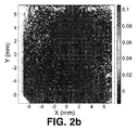
適用例で詳述しているパラメータを用いて、この表面上で取得した三次元OCT画像に、本発明で説明している方法を適用した。トポグラフィックデータ(表面形状測定装置とOCT、未分析(crude)データ、および次の走査歪みの較正/補正の)を、(曲率半径と非球面性を特徴とする)双円錐関数(biconical function)と8次の(order 8)ゼルニケ多項式に応じて調整した。較正または補正なしのOCT表面に対して調整された曲率半径の、非接触の表面形状プロファイルの調整に対する相違は4.6%であり、較正後の相違は1.6%であった。非球面性の相違は130%から5%まで減少した。図2aは、表面と、較正前の表面形状プロファイルの調整との間の差のマップを示す。図2bは、表面と、本発明の目的である較正方法の適用後の表面形状プロファイルの調整との間の差のマップを示す。 The method described in the present invention was applied to the three-dimensional OCT image acquired on this surface using the parameters detailed in the application example. Topographic data (surface profiler and OCT, crude data, and subsequent scan distortion calibration / correction), biconical function (characterized by radius of curvature and asphericity) And an 8th order (order 8) Zernike polynomial. The difference in radius of curvature adjusted for an OCT surface without calibration or correction was 4.6% for adjustment of the non-contact surface shape profile, and the difference after calibration was 1.6%. The difference in asphericity decreased from 130% to 5%. FIG. 2a shows a map of the difference between the surface and the adjustment of the surface shape profile before calibration. FIG. 2b shows a map of the difference between the surface and the adjustment of the surface shape profile after application of the calibration method which is the object of the present invention.
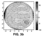
本発明の目的である方法を人間の角膜に適用した別の例の実施形態では、測定した患者は、通常の若年被験者であった。被験者は、角膜曲率測定により測定した乳頭軸(karatometric papillary axis)を機器の光軸に一致させることを可能にする刺激に対して視点を固定した。OCT画像取得時間は0.72秒である。適用例に記載のパラメータを用いて、本発明で説明している方法を、前部角膜面から取得した三次元OCT画像に適用した。双円錐面と8次のゼルニケ多項式に応じてトポグラフィックデータを調整した。走査歪みの補正は、表面の非対称性を5.7%(曲率半径)と9.5%(非曲面性)に低下させた。補正前後の角膜の頂点曲率半径はそれぞれ7.38mmと7.59mmであり、非球面性はそれぞれ−0.38、−0.42であった。図3aは、走査歪み補正を適用する前に、OCTにより取得した、患者の角膜前面の(ゼルニケ多項式に応じて調整された)トポグラフィックマップを示す。図3bは、走査歪み補正を適用した後の、角膜前面の前記トポグラフィックマップを示す。図3a、図3bともに、大きい方の球を予め減算している。 In another example embodiment where the method that is the object of the present invention is applied to a human cornea, the measured patient was a normal young subject. The subject fixed his viewpoint to a stimulus that allowed the karatometric papillary axis measured by corneal curvature measurement to coincide with the optical axis of the instrument. The OCT image acquisition time is 0.72 seconds. Using the parameters described in the application examples, the method described in the present invention was applied to a three-dimensional OCT image acquired from the anterior corneal surface. The topographic data was adjusted according to the biconic surface and the 8th order Zernike polynomial. The correction of scanning distortion reduced the surface asymmetry to 5.7% (curvature radius) and 9.5% (non-curved surface). The apex curvature radii of the cornea before and after correction were 7.38 mm and 7.59 mm, respectively, and the asphericity was −0.38 and −0.42, respectively. FIG. 3a shows a topographic map (adjusted according to Zernike polynomials) of the anterior cornea of the patient, obtained by OCT before applying scan distortion correction. FIG. 3b shows the topographic map of the anterior cornea after applying scanning distortion correction. In both FIG. 3a and FIG. 3b, the larger sphere is subtracted in advance.
Claims (6)
i)複数の実座標で記述される複数の既知の基準点を含む基準パターンを選択するステップ、
ii)光コヒーレンストモグラフィシステムにより基準パターンの画像を取得するステップ、ここで該基準パターンは、ステップi)で選択されて光コヒーレンストモグラフィシステムのオブジェクト空間内に配置され、
iii)取得された基準パターンの画像において、光コヒーレンストモグラフィシステムにより付与される複数のローカル座標で記述され、ステップi)での既知の基準点に対応する複数の基準点の複数の位置を特定するステップ、
iv)光コヒーレンストモグラフィシステムにより付与されるローカル座標と複数の実座標との間の変換を規定する数学的歪み関係を取得するステップ、ここで該数学的関係は、ステップiii)のローカル座標とステップi)の実座標で、既知の基準点の位置を比較することに基づき、
v)ステップiv)で取得される数学的歪み関係を、光コヒーレンストモグラフィシステムにより取得されるデータに適用することにより、歪みを補正するステップ、
を含むことを特徴とする方法。 A method for calibrating and correcting scanning distortion of an optical coherence tomography system comprising:
i) selecting a reference pattern including a plurality of known reference points described by a plurality of real coordinates;
ii) acquiring an image of a reference pattern with an optical coherence tomography system, wherein the reference pattern is selected in step i) and placed in the object space of the optical coherence tomography system;
iii) In the acquired reference pattern image, a plurality of positions of a plurality of reference points described by a plurality of local coordinates given by the optical coherence tomography system and corresponding to the known reference points in step i) are specified. Step to do,
iv) obtaining a mathematical distortion relationship that defines a transformation between the local coordinates provided by the optical coherence tomography system and a plurality of real coordinates, wherein the mathematical relation is defined as the local coordinates of step iii) Based on comparing the position of the known reference point with the real coordinates of step i),
v) correcting the distortion by applying the mathematical distortion relationship acquired in step iv) to the data acquired by the optical coherence tomography system;
A method comprising the steps of:
三次元較正用格子であり、ここで既知の基準点は該三次元較正用格子の節点であり、
較正された変位直線エレメントの上に搭載された二次元較正用格子であり、ここで既知の基準点は、種々の軸方向の位置にある較正用格子の節点であり、
彫刻された三次元較正用格子を有する立方体であり、ここで既知の基準点は該三次元較正用格子の節点であり、および、
階段状パターンであり、ここで既知の基準パターンは、段の間での深さ推移の急峻性である、のいずれかから選択されることを特徴とする、請求項1に記載の光コヒーレンストモグラフィシステムの走査歪みを較正および補正する方法。 The reference pattern of step i) is
A three-dimensional calibration grid, where the known reference points are the nodes of the three-dimensional calibration grid;
A two-dimensional calibration grid mounted on a calibrated displacement linear element, where the known reference points are the nodes of the calibration grid at various axial positions;
A cube with an engraved three-dimensional calibration grid, where the known reference point is a node of the three-dimensional calibration grid; and
The optical coherence tomograph according to claim 1, characterized in that it is a stepped pattern, wherein the known reference pattern is selected from one of the steepness of the depth transition between the steps. A method for calibrating and correcting scanning distortion of a graphy system.
三次元ボリュームデータ、
角膜トポグラフィデータ、
網膜トポグラフィデータ
光学歪みおよび屈折の補償と組み合わせた眼の内表面のデータ、
前眼部の画像データ、
網膜層の画像データ、
光コヒーレンストモグラフィの光検出器内で取得された信号データ、
強度画像およびボリュームデータ、
予め画像から抽出した複数のエッジに対応する点のマップデータ、
予め光コヒーレンストモグラフィ画像から抽出したエッジの数に適合した表面のデータ
から選択される走査歪みの較正および補正データを、光コヒーレンストモグラフィから取得するための請求項1から5のいずれか1項に記載の方法の使用。 2D section data,
3D volume data,
Corneal topography data,
Retinal topography data Internal eye data combined with optical distortion and refraction compensation,
Anterior eye image data,
Retinal layer image data,
Signal data acquired in the optical coherence tomography photodetector,
Intensity image and volume data,
Map data of points corresponding to a plurality of edges previously extracted from the image,
6. Scan distortion calibration and correction data selected from surface data adapted to the number of edges previously extracted from an optical coherence tomography image, for obtaining from the optical coherence tomography data. Use of the method described in.
Applications Claiming Priority (3)
| Application Number | Priority Date | Filing Date | Title |
|---|---|---|---|
| ESP201130685 | 2011-04-29 | ||
| ES201130685A ES2391510B1 (en) | 2011-04-29 | 2011-04-29 | CALIBRATION AND CORRECTION PROCEDURE OF THE SWEEP DISTORSION OF AN OPTICAL COHERENCE TOMOGRAPHY SYSTEM |
| PCT/ES2012/070185 WO2012146811A1 (en) | 2011-04-29 | 2012-03-21 | Method for calibrating and correcting the scanning distortion of an optical coherence tomography system |
Publications (2)
| Publication Number | Publication Date |
|---|---|
| JP2014512242A true JP2014512242A (en) | 2014-05-22 |
| JP2014512242A5 JP2014512242A5 (en) | 2015-05-07 |
Family
ID=47071640
Family Applications (1)
| Application Number | Title | Priority Date | Filing Date |
|---|---|---|---|
| JP2014506915A Pending JP2014512242A (en) | 2011-04-29 | 2012-03-21 | Method for calibrating and correcting scanning distortion in an optical coherence tomography system |
Country Status (5)
| Country | Link |
|---|---|
| US (1) | US9593933B2 (en) |
| EP (1) | EP2704095B1 (en) |
| JP (1) | JP2014512242A (en) |
| ES (1) | ES2391510B1 (en) |
| WO (1) | WO2012146811A1 (en) |
Cited By (2)
| Publication number | Priority date | Publication date | Assignee | Title |
|---|---|---|---|---|
| JP2014121606A (en) * | 2012-12-21 | 2014-07-03 | Optos Plc | Improvement in ophthalmoscope |
| JP2021053198A (en) * | 2019-09-30 | 2021-04-08 | 株式会社ニデック | Ophthalmology imaging apparatus |
Families Citing this family (14)
| Publication number | Priority date | Publication date | Assignee | Title |
|---|---|---|---|---|
| ITFI20130067A1 (en) * | 2013-03-26 | 2014-09-27 | Strumenti Oftalmici C S O S R L Costruzioni | PROCEDURE AND TOMOGRAPHY SYSTEM WITH OPTICAL CONSISTENCY |
| GB201307990D0 (en) | 2013-05-02 | 2013-06-12 | Optos Plc | Improvements in and relating to imaging of the eye |
| US9733152B2 (en) | 2013-12-17 | 2017-08-15 | Bioptigen, Inc. | Immersion lens assemblies for use in optical coherence tomography systems |
| WO2017125570A1 (en) * | 2016-01-22 | 2017-07-27 | 3Shape A/S | Encoder for optical coherence tomography scanner |
| EP3510562A1 (en) | 2016-09-07 | 2019-07-17 | Starship Technologies OÜ | Method and system for calibrating multiple cameras |
| WO2018167696A1 (en) * | 2017-03-14 | 2018-09-20 | Narayana Nethralaya Foundation | A system and method of artificial intelligence and tomography imaging of human cornea |
| CN107737410B (en) * | 2017-10-12 | 2024-04-09 | 佛山科学技术学院 | Vitiligo treatment system and implementation method thereof |
| EP4085819B1 (en) | 2018-05-11 | 2023-12-20 | Optos plc | Oct image processing |
| KR102145381B1 (en) * | 2018-05-21 | 2020-08-19 | 주식회사 고영테크놀러지 | Oct system, method of generating oct image and storage medium |
| CN109887037B (en) * | 2019-01-22 | 2023-03-14 | 西安工程大学 | Calibration method suitable for oblique laser interferometry lens imaging distortion |
| WO2021081157A1 (en) * | 2019-10-22 | 2021-04-29 | The Uab Research Foundation | Distortion correction for optical coherence tomography |
| KR102449039B1 (en) * | 2021-02-19 | 2022-09-29 | (주) 휴비츠 | Optical tomography oral scanner correction device and method of obtaining correction information through full area scan |
| KR102625950B1 (en) * | 2021-12-20 | 2024-01-17 | 주식회사 휴비츠 | Calibration method of optical coherence tomography device |
| DE102022104416A1 (en) | 2022-02-24 | 2023-08-24 | Precitec Optronik Gmbh | Device and method for measuring wafers |
Citations (3)
| Publication number | Priority date | Publication date | Assignee | Title |
|---|---|---|---|---|
| US20090261240A1 (en) * | 2008-02-07 | 2009-10-22 | Daisuke Watanabe | Calibration jig for optical tomographic imaging apparatus and method for generating a calibration conversion table |
| JP2010014458A (en) * | 2008-07-02 | 2010-01-21 | Fujifilm Corp | Calibration jig |
| JP2011158309A (en) * | 2010-01-29 | 2011-08-18 | Japan Health Science Foundation | Standard lattice, method of using standard lattice, and optical interference tomographic image diagnostic apparatus with standard lattice |
Family Cites Families (9)
| Publication number | Priority date | Publication date | Assignee | Title |
|---|---|---|---|---|
| US716313A (en) | 1902-02-24 | 1902-12-16 | John S Thurman | Carpet-renovator. |
| US5005578A (en) * | 1986-12-16 | 1991-04-09 | Sam Technology, Inc. | Three-dimensional magnetic resonance image distortion correction method and system |
| US5491524A (en) | 1994-10-05 | 1996-02-13 | Carl Zeiss, Inc. | Optical coherence tomography corneal mapping apparatus |
| US7092581B2 (en) * | 2001-11-23 | 2006-08-15 | Imaging Dynamics Company Ltd. | Balancing areas of varying density in a digital image |
| JP2005261487A (en) * | 2004-03-16 | 2005-09-29 | Fuji Photo Film Co Ltd | Method and apparatus for reading radiograph |
| CA2595324C (en) * | 2005-01-21 | 2015-08-11 | Massachusetts Institute Of Technology | Methods and apparatus for optical coherence tomography scanning |
| US7416300B2 (en) | 2006-05-25 | 2008-08-26 | Coopervision International Holding Company, Lp | Measurement of lenses and lens molds using optical coherence tomography |
| US10028722B2 (en) * | 2007-09-25 | 2018-07-24 | Hospital For Special Surgery | Methods and apparatus for assisting cartilage diagnostic and therapeutic procedures |
| US7878651B2 (en) | 2007-12-26 | 2011-02-01 | Carl Zeiss Meditec, Inc. | Refractive prescription using optical coherence tomography |
-
2011
- 2011-04-29 ES ES201130685A patent/ES2391510B1/en not_active Expired - Fee Related
-
2012
- 2012-03-21 WO PCT/ES2012/070185 patent/WO2012146811A1/en active Application Filing
- 2012-03-21 JP JP2014506915A patent/JP2014512242A/en active Pending
- 2012-03-21 EP EP12777359.6A patent/EP2704095B1/en active Active
- 2012-03-21 US US14/114,254 patent/US9593933B2/en active Active
Patent Citations (3)
| Publication number | Priority date | Publication date | Assignee | Title |
|---|---|---|---|---|
| US20090261240A1 (en) * | 2008-02-07 | 2009-10-22 | Daisuke Watanabe | Calibration jig for optical tomographic imaging apparatus and method for generating a calibration conversion table |
| JP2010014458A (en) * | 2008-07-02 | 2010-01-21 | Fujifilm Corp | Calibration jig |
| JP2011158309A (en) * | 2010-01-29 | 2011-08-18 | Japan Health Science Foundation | Standard lattice, method of using standard lattice, and optical interference tomographic image diagnostic apparatus with standard lattice |
Cited By (4)
| Publication number | Priority date | Publication date | Assignee | Title |
|---|---|---|---|---|
| JP2014121606A (en) * | 2012-12-21 | 2014-07-03 | Optos Plc | Improvement in ophthalmoscope |
| JP2021053198A (en) * | 2019-09-30 | 2021-04-08 | 株式会社ニデック | Ophthalmology imaging apparatus |
| JP7367433B2 (en) | 2019-09-30 | 2023-10-24 | 株式会社ニデック | Ophthalmology imaging device |
| US11877798B2 (en) | 2019-09-30 | 2024-01-23 | Nidek Co., Ltd. | Ophthalmologic imaging apparatus |
Also Published As
| Publication number | Publication date |
|---|---|
| EP2704095A1 (en) | 2014-03-05 |
| US9593933B2 (en) | 2017-03-14 |
| US20140107960A1 (en) | 2014-04-17 |
| ES2391510B1 (en) | 2013-11-11 |
| ES2391510A1 (en) | 2012-11-27 |
| WO2012146811A1 (en) | 2012-11-01 |
| EP2704095B1 (en) | 2015-07-01 |
| EP2704095A4 (en) | 2014-11-05 |
Similar Documents
| Publication | Publication Date | Title |
|---|---|---|
| JP2014512242A (en) | Method for calibrating and correcting scanning distortion in an optical coherence tomography system | |
| US10512395B2 (en) | Montaging of wide-field fundus images | |
| KR101442519B1 (en) | Optical coherence tomographic imaging method and optical coherence tomographic imaging apparatus | |
| JP3549961B2 (en) | Optical coherence tomography corneal mapping system | |
| CN104684458B (en) | For reliably determining the device of the bio-identification measurand of whole eyes | |
| JP5685013B2 (en) | Optical tomographic imaging apparatus, control method therefor, and program | |
| US9733152B2 (en) | Immersion lens assemblies for use in optical coherence tomography systems | |
| TWI291013B (en) | Digital-structured micro-optic three-dimensional confocal surface profile measuring system and technique | |
| US20130027515A1 (en) | Scanning of cavities with restricted accessibility | |
| US20110301455A1 (en) | Optical tomographic imaging apparatus | |
| CN112987288A (en) | Confocal imaging apparatus with curved focal plane or target reference element and field compensator | |
| CA2668950A1 (en) | Improvements in or relating to retinal scanning | |
| WO2004006751A2 (en) | Method and device for quantitative image correction for optical coherence tomography | |
| Pande et al. | A mosaicking approach for in vivo thickness mapping of the human tympanic membrane using low coherence interferometry | |
| JP2015505039A (en) | Non-contact surface shape evaluation using modulated light | |
| WO2021106987A1 (en) | Medical image processing device, optical coherence tomography device, medical image processing method, and program | |
| CN110325101B (en) | Method and device for high-resolution topographic mapping of the cornea of an eye | |
| JP6616673B2 (en) | Corneal inspection device | |
| CN111627085B (en) | Wavefront split-field curvature sensing method and device and self-adaptive OCT system | |
| JP2013075035A (en) | Ophthalmic apparatus, ophthalmic image processing method, and recording medium | |
| Escamilla et al. | Three-dimensional surface measurement based on the projected defocused pattern technique using imaging fiber optics | |
| CN110383019A (en) | Hand-held imaging instrument system and application method based on image | |
| Ralston et al. | Phase stability technique for inverse scattering in optical coherence tomography | |
| JP5893248B2 (en) | Optical tomographic imaging method and optical tomographic imaging apparatus | |
| CN112393694B (en) | Measurement method for improving precision of photoelectric autocollimator based on pixel frequency domain calibration |
Legal Events
| Date | Code | Title | Description |
|---|---|---|---|
| A521 | Request for written amendment filed |
Free format text: JAPANESE INTERMEDIATE CODE: A523 Effective date: 20150319 |
|
| A621 | Written request for application examination |
Free format text: JAPANESE INTERMEDIATE CODE: A621 Effective date: 20150319 |
|
| A977 | Report on retrieval |
Free format text: JAPANESE INTERMEDIATE CODE: A971007 Effective date: 20160129 |
|
| A131 | Notification of reasons for refusal |
Free format text: JAPANESE INTERMEDIATE CODE: A131 Effective date: 20160209 |
|
| A02 | Decision of refusal |
Free format text: JAPANESE INTERMEDIATE CODE: A02 Effective date: 20160927 |