JP2014509174A - Charge management method for rechargeable battery of automobile vehicle - Google Patents
Charge management method for rechargeable battery of automobile vehicle Download PDFInfo
- Publication number
- JP2014509174A JP2014509174A JP2013549871A JP2013549871A JP2014509174A JP 2014509174 A JP2014509174 A JP 2014509174A JP 2013549871 A JP2013549871 A JP 2013549871A JP 2013549871 A JP2013549871 A JP 2013549871A JP 2014509174 A JP2014509174 A JP 2014509174A
- Authority
- JP
- Japan
- Prior art keywords
- module
- battery
- cell
- computer
- charge management
- Prior art date
- Legal status (The legal status is an assumption and is not a legal conclusion. Google has not performed a legal analysis and makes no representation as to the accuracy of the status listed.)
- Pending
Links
Images


Classifications
-
- H—ELECTRICITY
- H01—ELECTRIC ELEMENTS
- H01M—PROCESSES OR MEANS, e.g. BATTERIES, FOR THE DIRECT CONVERSION OF CHEMICAL ENERGY INTO ELECTRICAL ENERGY
- H01M10/00—Secondary cells; Manufacture thereof
- H01M10/42—Methods or arrangements for servicing or maintenance of secondary cells or secondary half-cells
- H01M10/48—Accumulators combined with arrangements for measuring, testing or indicating the condition of cells, e.g. the level or density of the electrolyte
- H01M10/486—Accumulators combined with arrangements for measuring, testing or indicating the condition of cells, e.g. the level or density of the electrolyte for measuring temperature
-
- B—PERFORMING OPERATIONS; TRANSPORTING
- B60—VEHICLES IN GENERAL
- B60L—PROPULSION OF ELECTRICALLY-PROPELLED VEHICLES; SUPPLYING ELECTRIC POWER FOR AUXILIARY EQUIPMENT OF ELECTRICALLY-PROPELLED VEHICLES; ELECTRODYNAMIC BRAKE SYSTEMS FOR VEHICLES IN GENERAL; MAGNETIC SUSPENSION OR LEVITATION FOR VEHICLES; MONITORING OPERATING VARIABLES OF ELECTRICALLY-PROPELLED VEHICLES; ELECTRIC SAFETY DEVICES FOR ELECTRICALLY-PROPELLED VEHICLES
- B60L3/00—Electric devices on electrically-propelled vehicles for safety purposes; Monitoring operating variables, e.g. speed, deceleration or energy consumption
- B60L3/0023—Detecting, eliminating, remedying or compensating for drive train abnormalities, e.g. failures within the drive train
- B60L3/0046—Detecting, eliminating, remedying or compensating for drive train abnormalities, e.g. failures within the drive train relating to electric energy storage systems, e.g. batteries or capacitors
-
- B—PERFORMING OPERATIONS; TRANSPORTING
- B60—VEHICLES IN GENERAL
- B60L—PROPULSION OF ELECTRICALLY-PROPELLED VEHICLES; SUPPLYING ELECTRIC POWER FOR AUXILIARY EQUIPMENT OF ELECTRICALLY-PROPELLED VEHICLES; ELECTRODYNAMIC BRAKE SYSTEMS FOR VEHICLES IN GENERAL; MAGNETIC SUSPENSION OR LEVITATION FOR VEHICLES; MONITORING OPERATING VARIABLES OF ELECTRICALLY-PROPELLED VEHICLES; ELECTRIC SAFETY DEVICES FOR ELECTRICALLY-PROPELLED VEHICLES
- B60L58/00—Methods or circuit arrangements for monitoring or controlling batteries or fuel cells, specially adapted for electric vehicles
- B60L58/10—Methods or circuit arrangements for monitoring or controlling batteries or fuel cells, specially adapted for electric vehicles for monitoring or controlling batteries
- B60L58/12—Methods or circuit arrangements for monitoring or controlling batteries or fuel cells, specially adapted for electric vehicles for monitoring or controlling batteries responding to state of charge [SoC]
- B60L58/15—Preventing overcharging
-
- B—PERFORMING OPERATIONS; TRANSPORTING
- B60—VEHICLES IN GENERAL
- B60L—PROPULSION OF ELECTRICALLY-PROPELLED VEHICLES; SUPPLYING ELECTRIC POWER FOR AUXILIARY EQUIPMENT OF ELECTRICALLY-PROPELLED VEHICLES; ELECTRODYNAMIC BRAKE SYSTEMS FOR VEHICLES IN GENERAL; MAGNETIC SUSPENSION OR LEVITATION FOR VEHICLES; MONITORING OPERATING VARIABLES OF ELECTRICALLY-PROPELLED VEHICLES; ELECTRIC SAFETY DEVICES FOR ELECTRICALLY-PROPELLED VEHICLES
- B60L58/00—Methods or circuit arrangements for monitoring or controlling batteries or fuel cells, specially adapted for electric vehicles
- B60L58/10—Methods or circuit arrangements for monitoring or controlling batteries or fuel cells, specially adapted for electric vehicles for monitoring or controlling batteries
- B60L58/24—Methods or circuit arrangements for monitoring or controlling batteries or fuel cells, specially adapted for electric vehicles for monitoring or controlling batteries for controlling the temperature of batteries
- B60L58/26—Methods or circuit arrangements for monitoring or controlling batteries or fuel cells, specially adapted for electric vehicles for monitoring or controlling batteries for controlling the temperature of batteries by cooling
-
- G—PHYSICS
- G01—MEASURING; TESTING
- G01R—MEASURING ELECTRIC VARIABLES; MEASURING MAGNETIC VARIABLES
- G01R31/00—Arrangements for testing electric properties; Arrangements for locating electric faults; Arrangements for electrical testing characterised by what is being tested not provided for elsewhere
- G01R31/36—Arrangements for testing, measuring or monitoring the electrical condition of accumulators or electric batteries, e.g. capacity or state of charge [SoC]
- G01R31/382—Arrangements for monitoring battery or accumulator variables, e.g. SoC
-
- H—ELECTRICITY
- H02—GENERATION; CONVERSION OR DISTRIBUTION OF ELECTRIC POWER
- H02J—CIRCUIT ARRANGEMENTS OR SYSTEMS FOR SUPPLYING OR DISTRIBUTING ELECTRIC POWER; SYSTEMS FOR STORING ELECTRIC ENERGY
- H02J7/00—Circuit arrangements for charging or depolarising batteries or for supplying loads from batteries
- H02J7/0029—Circuit arrangements for charging or depolarising batteries or for supplying loads from batteries with safety or protection devices or circuits
- H02J7/00302—Overcharge protection
-
- H—ELECTRICITY
- H02—GENERATION; CONVERSION OR DISTRIBUTION OF ELECTRIC POWER
- H02J—CIRCUIT ARRANGEMENTS OR SYSTEMS FOR SUPPLYING OR DISTRIBUTING ELECTRIC POWER; SYSTEMS FOR STORING ELECTRIC ENERGY
- H02J7/00—Circuit arrangements for charging or depolarising batteries or for supplying loads from batteries
- H02J7/0029—Circuit arrangements for charging or depolarising batteries or for supplying loads from batteries with safety or protection devices or circuits
- H02J7/0031—Circuit arrangements for charging or depolarising batteries or for supplying loads from batteries with safety or protection devices or circuits using battery or load disconnect circuits
-
- H—ELECTRICITY
- H02—GENERATION; CONVERSION OR DISTRIBUTION OF ELECTRIC POWER
- H02J—CIRCUIT ARRANGEMENTS OR SYSTEMS FOR SUPPLYING OR DISTRIBUTING ELECTRIC POWER; SYSTEMS FOR STORING ELECTRIC ENERGY
- H02J7/00—Circuit arrangements for charging or depolarising batteries or for supplying loads from batteries
- H02J7/007—Regulation of charging or discharging current or voltage
- H02J7/007188—Regulation of charging or discharging current or voltage the charge cycle being controlled or terminated in response to non-electric parameters
- H02J7/007192—Regulation of charging or discharging current or voltage the charge cycle being controlled or terminated in response to non-electric parameters in response to temperature
- H02J7/007194—Regulation of charging or discharging current or voltage the charge cycle being controlled or terminated in response to non-electric parameters in response to temperature of the battery
-
- B—PERFORMING OPERATIONS; TRANSPORTING
- B60—VEHICLES IN GENERAL
- B60L—PROPULSION OF ELECTRICALLY-PROPELLED VEHICLES; SUPPLYING ELECTRIC POWER FOR AUXILIARY EQUIPMENT OF ELECTRICALLY-PROPELLED VEHICLES; ELECTRODYNAMIC BRAKE SYSTEMS FOR VEHICLES IN GENERAL; MAGNETIC SUSPENSION OR LEVITATION FOR VEHICLES; MONITORING OPERATING VARIABLES OF ELECTRICALLY-PROPELLED VEHICLES; ELECTRIC SAFETY DEVICES FOR ELECTRICALLY-PROPELLED VEHICLES
- B60L2240/00—Control parameters of input or output; Target parameters
- B60L2240/40—Drive Train control parameters
- B60L2240/54—Drive Train control parameters related to batteries
- B60L2240/545—Temperature
-
- H—ELECTRICITY
- H01—ELECTRIC ELEMENTS
- H01M—PROCESSES OR MEANS, e.g. BATTERIES, FOR THE DIRECT CONVERSION OF CHEMICAL ENERGY INTO ELECTRICAL ENERGY
- H01M2220/00—Batteries for particular applications
- H01M2220/20—Batteries in motive systems, e.g. vehicle, ship, plane
-
- Y—GENERAL TAGGING OF NEW TECHNOLOGICAL DEVELOPMENTS; GENERAL TAGGING OF CROSS-SECTIONAL TECHNOLOGIES SPANNING OVER SEVERAL SECTIONS OF THE IPC; TECHNICAL SUBJECTS COVERED BY FORMER USPC CROSS-REFERENCE ART COLLECTIONS [XRACs] AND DIGESTS
- Y02—TECHNOLOGIES OR APPLICATIONS FOR MITIGATION OR ADAPTATION AGAINST CLIMATE CHANGE
- Y02E—REDUCTION OF GREENHOUSE GAS [GHG] EMISSIONS, RELATED TO ENERGY GENERATION, TRANSMISSION OR DISTRIBUTION
- Y02E60/00—Enabling technologies; Technologies with a potential or indirect contribution to GHG emissions mitigation
- Y02E60/10—Energy storage using batteries
-
- Y—GENERAL TAGGING OF NEW TECHNOLOGICAL DEVELOPMENTS; GENERAL TAGGING OF CROSS-SECTIONAL TECHNOLOGIES SPANNING OVER SEVERAL SECTIONS OF THE IPC; TECHNICAL SUBJECTS COVERED BY FORMER USPC CROSS-REFERENCE ART COLLECTIONS [XRACs] AND DIGESTS
- Y02—TECHNOLOGIES OR APPLICATIONS FOR MITIGATION OR ADAPTATION AGAINST CLIMATE CHANGE
- Y02T—CLIMATE CHANGE MITIGATION TECHNOLOGIES RELATED TO TRANSPORTATION
- Y02T10/00—Road transport of goods or passengers
- Y02T10/60—Other road transportation technologies with climate change mitigation effect
- Y02T10/70—Energy storage systems for electromobility, e.g. batteries
Abstract
少なくとも1つの電気化学セルを含む少なくとも1つのモジュールを備える充電式バッテリの充電管理方法において、その少なくとも1つのモジュール内に発生する熱流束を、当該モジュールのセル全体の内部抵抗を推定するオブザーバを利用して推定する段階を含むことを特徴とする方法。 In a charge management method for a rechargeable battery including at least one module including at least one electrochemical cell, an observer that estimates an internal resistance of the entire cell of the module is used for heat flux generated in the at least one module And estimating the method.
Description
本発明は、1対の電気化学セルを含む少なくとも1つのモジュールを備える充電式バッテリの充電管理方法、または1対の電気化学セルを含む少なくとも1つのモジュールを備える充電式バッテリの充電管理装置の動作方法に関する。本発明はまた、その方法を実装する装置およびその装置を備える自動車車両にも関する。本発明はさらに、その方法を実装するためのデータ記憶媒体にも関する。 The present invention relates to a charge management method for a rechargeable battery including at least one module including a pair of electrochemical cells, or an operation of a charge management apparatus for a rechargeable battery including at least one module including a pair of electrochemical cells. Regarding the method. The invention also relates to a device for implementing the method and a motor vehicle equipped with the device. The invention further relates to a data storage medium for implementing the method.
1対の並列のセルの端子間で測定した電圧が閾値を超えた時点で電気車両のバッテリの充電を止めることが知られている。過充電の危険性を考えると、この停止はできるだけ高い信頼性を備えている必要がある。この測定に使用される電圧センサに本来的に備わる信頼性は、それ自体きわめて高いものであっても、あらゆるケースで充電の停止を保証するには十分とは言えない。そのため、場合によってはセルの過充電が起こる。すると、バッテリを傷め、さらにはバッテリの機能を壊しかねない副反応がその過充電によって始まることになる。さらに厄介なことに、その副反応は有毒ガスを発生させる可能性もある。また、発熱反応によって発生する熱流束がセルから外部環境に放散される熱流束を超えると、熱暴走が起こり、たとえ充電を止めても、バッテリは多少なりとも激しく破損することになる。 It is known to stop charging the battery of an electric vehicle when the voltage measured between the terminals of a pair of parallel cells exceeds a threshold value. Given the danger of overcharging, this stop must be as reliable as possible. Even if the inherent reliability of the voltage sensor used for this measurement is extremely high, it cannot be said to be sufficient to guarantee the stopping of charging in all cases. Therefore, in some cases, the cell is overcharged. Then, a side reaction that can damage the battery and possibly destroy the function of the battery is started by the overcharge. To make matters worse, the side reactions can generate toxic gases. Further, if the heat flux generated by the exothermic reaction exceeds the heat flux dissipated from the cell to the external environment, thermal runaway occurs, and even if charging is stopped, the battery will be severely damaged somewhat.
上に説明したように、充電の停止が電圧の測定を介して行われる場合、その測定に不具合があると、バッテリの充電電流を止められなかったり、しかるべきタイミングで止めることができなかったりする。 As explained above, when charging is stopped via voltage measurement, if the measurement fails, the charging current of the battery cannot be stopped or cannot be stopped at an appropriate timing. .
この不測の事態に対処するために現在行われている解決法は、互いに完全に独立した冗長な2つのシステムによって電圧を測定するというものである。 The current solution to deal with this contingency is to measure the voltage with two redundant systems that are completely independent of each other.
一方、バッテリのあらゆる過充電電流をしかるべきタイミングで止めるために、モジュールの温度測定値を利用することによってセルの過充電を検出する信頼性のある指標を定義し、利用することは全くもって意義あることであると考えられる。この指標は、その上で、充電をしかるべきタイミングで止めるための過充電検出論理の中で利用される。この指標は、バッテリ管理計算機によって管理される充電の停止論理とは独立した補完物であることができる。 On the other hand, defining and using a reliable indicator to detect cell overcharge by using module temperature measurements to stop any overcharge current of the battery at the right time is quite meaningful. It is considered to be. This index is then used in overcharge detection logic to stop charging at the appropriate time. This indicator can be a complement that is independent of the charge stop logic managed by the battery management computer.
温度測定を直接利用するだけでは、過充電の検出に十分たり得ないことはすでに指摘されている。温度測定に基づいて熱暴走前に過充電を検出することは不可能であることは研究によって示されている。これは、そうした戦略には低い温度閾値の利用が前提となることが考えられるが、その閾値はバッテリ利用の最適化に反する、したがって車両の利用可能性に反するものである。 It has already been pointed out that direct use of temperature measurement is not sufficient to detect overcharge. Studies have shown that it is impossible to detect overcharge prior to thermal runaway based on temperature measurements. This may be premised on the use of a low temperature threshold for such a strategy, but that threshold goes against the optimization of battery usage and therefore against the availability of the vehicle.
バッテリ充電を止めるための温度測定値の利用は、米国特許出願公開第2005/0137823号、特開2010−016944号および仏国特許第2926165号にそれぞれ記載されている。 The use of temperature measurements to stop battery charging is described in US Patent Application Publication No. 2005/0137823, Japanese Patent Application Laid-Open No. 2010-016944 and French Patent No. 2926165, respectively.
本発明の目的は、上に述べた問題を解決できるとともに、周知の先行技術による充電管理方法を改善するものである充電管理方法を提供することにある。とりわけ、本発明は、最適で信頼性のあるバッテリ利用を可能にする充電管理方法を提案する。 It is an object of the present invention to provide a charge management method that can solve the above-described problems and improve a well-known prior art charge management method. In particular, the present invention proposes a charge management method that enables optimal and reliable battery utilization.
本発明によれば、その方法は、少なくとも1つの電気化学セルを含む少なくとも1つのモジュールを備える充電式バッテリの充電を管理することができる。その方法は、少なくとも1つのモジュールのセル全体の内部抵抗を推定するオブザーバを利用して当該モジュールで発生する熱流束を推定する段階を含む。 According to the invention, the method can manage the charging of a rechargeable battery comprising at least one module comprising at least one electrochemical cell. The method includes estimating a heat flux generated in the module using an observer that estimates an internal resistance of the entire cell of at least one module.
その推定段階は、その少なくとも1つのセルを含むその少なくとも1つのモジュールの熱モデルの定義ステップ、および/またはその少なくとも1つのセルを含むその少なくとも1つのモジュールの温度の測定ステップを含むことができる。 The estimating step may include defining a thermal model of the at least one module including the at least one cell and / or measuring a temperature of the at least one module including the at least one cell.
その少なくとも1つのモジュール内に発生する熱流束の推定を利用して、その少なくとも1つのモジュールまたはバッテリの充電の停止操作を決定することができる。 An estimate of the heat flux generated within the at least one module can be used to determine a stop operation for charging the at least one module or battery.
推定される全体の内部抵抗があらかじめ定められた閾値を超えるか、または他のモジュールで推定される内部抵抗と著しく異なる場合に、その少なくとも1つのモジュールまたはバッテリの充電を止めることができる。 If the estimated overall internal resistance exceeds a predetermined threshold or is significantly different from the estimated internal resistance of other modules, the charging of the at least one module or battery can be stopped.
本発明はまた、計算機が読み取ることができるデータ記録媒体であって、前に定義した管理方法の段階および/またはステップを実装するコンピュータプログラムのコード手段を含むコンピュータプログラムが記録された媒体にも関する。 The invention also relates to a computer readable data recording medium on which a computer program is recorded, including computer program code means implementing the steps and / or steps of the management method defined above. .
本発明によれば、少なくとも1つの電気化学セルを含む少なくとも1つのモジュールを備える充電式バッテリの充電管理装置は、前に定義した管理方法の実装のためのハードウェアおよび/またはソフトウェア手段を含むことを特徴とする。 According to the present invention, a rechargeable battery charge management device comprising at least one module comprising at least one electrochemical cell comprises hardware and / or software means for the implementation of the previously defined management method. It is characterized by.
ハードウェアおよび/またはソフトウェア手段は、その少なくとも1つのモジュールで発生する熱流束の推定手段を含むことができる。 The hardware and / or software means may include means for estimating heat flux generated in the at least one module.
少なくとも1つのモジュールで発生する熱流束の推定手段は、前記1つまたは複数のセルを含むモジュールの温度の測定手段と、その少なくとも1つのセルの熱モデル化手段とを含むことができる。 The means for estimating the heat flux generated in the at least one module may include means for measuring the temperature of the module including the one or more cells, and means for thermal modeling of the at least one cell.
この装置は、バッテリ充電器およびバッテリ充電器の制御手段、ならびに/またはバッテリ充電器とその少なくとも1つのモジュールとの接続もしくは切離しのために操作されるスイッチを含むことができる。 The apparatus can include a battery charger and battery charger control means, and / or a switch operated to connect or disconnect the battery charger and its at least one module.
本発明によれば、自動車車両、とりわけ電気式またはハイブリッド式自動車車両が前に定義した装置を含む。 According to the invention, an automobile vehicle, in particular an electric or hybrid automobile vehicle, includes the device as defined above.
本発明によれば、コンピュータプログラムは、プログラムがコンピュータ上または車載計算機上で動作するとき、上に定義した方法の段階および/またはステップを実施するように適合されたコンピュータプログラムのコード手段を含む。 According to the invention, the computer program comprises computer program code means adapted to carry out the method steps and / or steps defined above when the program runs on a computer or on-board computer.
添付の各図面は、本発明による管理方法の1つの実施形態を実装する充電管理装置の1つの実施形態を例示するものである。 The accompanying drawings illustrate one embodiment of a charge management device that implements one embodiment of the management method according to the present invention.
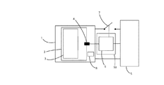
図1に示す設備は、充電式バッテリ1、充電器5およびバッテリ充電管理装置10を備える。これにより、バッテリは、充電管理装置による制御のもとで充電器によって充電することができる。
The equipment shown in FIG. 1 includes a
バッテリはあらゆる種類のものであってよい。好ましくは、自動車車両のバッテリ、とりわけ電気車両またはハイブリッド車両の駆動用電動機の電源バッテリである。 The battery can be of any kind. Preferably, it is a battery of a motor vehicle, in particular, a power source battery for a driving motor of an electric vehicle or a hybrid vehicle.
バッテリは、1つもしくは複数の電気化学セル3または電気化学蓄電池を筐体内に収めた1つまたは複数のモジュール2を備える。同一モジュールに属する電気化学セルは互いに電気的に接続される。同様に、バッテリのモジュールは互いに電気的に接続される。その一方で、バッテリはバッテリ管理計算機8を備える。バッテリは、その2つの端子の間に電気エネルギーを供給することができる一方、充電されるときは、その2つの端子の間に電気エネルギーを受け取ることができる。計算機8は、バッテリの充電終了を、それによって動作不良を引き起こすことがないようにしながら、その間に行わなければならない通常動作状態を検出することなどができる充電管理手段を備える。この管理手段はその充電の停止を操作することもできる。
The battery comprises one or more
充電器はあらゆる形式のものであってよい。充電器は、充電しようとするバッテリの特徴に適合したものである。充電器は、操作されるスイッチ7によってバッテリに接続し、またはバッテリから切り離すことができる。
The charger may be of any type. The charger is adapted to the characteristics of the battery to be charged. The charger can be connected to or disconnected from the battery by a
バッテリ充電管理装置10は、とりわけ、バッテリが充電された状態を検出するほか、場合により、充電器によるバッテリの充電の停止を操作することができる。そのため、充電管理装置は、本発明による充電管理方法を実装するためのハードウェアおよび/またはソフトウェア手段を備える。言い換えれば、充電管理装置は、本発明の対象である方法に従って自らの動作をコントロールすることができるハードウェアおよび/またはソフトウェア手段を備える。
In particular, the battery
管理装置は、計算機6、すなわち、図2を参照しながら以下に説明する制御手段を備える。計算機は、たとえばモジュールの温度測定信号を受け取り、さらに場合に応じてデータバス11を通るその他の信号を受け取る。温度測定信号は、フィルタ手段13によってフィルタリングされる。フィルタリングされた測定信号、および場合に応じたデータバス11を通るその他の信号は、次いで、モジュールの熱モデル15などが含まれる計算手段14に供給される。この計算手段は、モジュールの異常動作の検出手段16に供給される信号を生成する。この検出手段は、モジュールの正常動作または異常動作を表わす論理信号、とりわけバッテリが過充電状態にあるか否かを表わす信号を出力側に供給する。この論理信号は、前述の論理信号の妥当性を確認できる妥当性確認手段17であって、バッテリが過充電状態にあることを示すか、または示さない信号を出力側に供給する妥当性確認手段17に対して供給される。妥当性確認手段は、たとえば、受け取る論理信号が所定の時間にわたって継続して入力側に存在する場合には、その論理信号を妥当であるものと判断する。
The management apparatus includes a
妥当性確認手段17の出力側に供給される信号は、充電器の制御および/またはバッテリ1の充電器5の接続もしくは切離しを行えるように操作されるスイッチ7の制御を可能にする。
The signal supplied to the output side of the validation means 17 makes it possible to control the charger and / or the
好ましくは、この操作されるスイッチは充電管理装置の一部をなす。同様に、好ましくは、温度判定手段4は充電管理装置の一部をなす。 Preferably, the operated switch forms part of the charge management device. Similarly, preferably, the temperature determination means 4 forms part of the charge management device.
本発明による充電管理方法の1つの実施形態を以下に説明する。 One embodiment of the charge management method according to the present invention will be described below.
すでに見たように、バッテリのあるセルが過充電になると、そのセルに移動した余分なエネルギーは好ましくない副反応を引き起こす。これらの副反応は気体の発生と温度の異常な反応をもたらす。本発明による方法では、この反応が解析の対象とされる。その方法は、過充電をしかるべきタイミングでやはり止められるように温度の異常な状態を検出することをよりどころとする。過電圧を十分早くに、すなわち熱暴走の前に検出するためには、センサだけで測定した温度情報では十分でなく、センサは必ずしも適切に配置されているわけではないという事情を考えれば、なおさらである。 As already seen, when a cell with a battery is overcharged, the extra energy transferred to that cell causes an undesirable side reaction. These side reactions result in abnormal gas evolution and temperature reactions. In the method according to the present invention, this reaction is the object of analysis. The method relies on detecting an abnormal temperature condition so that overcharging can be stopped at an appropriate timing. In order to detect overvoltage quickly enough, that is, before thermal runaway, the temperature information measured by the sensor alone is not enough, especially when considering that the sensor is not always properly positioned. is there.
この熱暴走に備えるには、温度信号を微分することによって温度勾配を知る必要があろう。この温度勾配は充電を止める場合の有益な指標になると考えられる。残念ながら、この微分は測定ノイズを増幅させることにしかならない。 To prepare for this thermal runaway, it will be necessary to know the temperature gradient by differentiating the temperature signal. This temperature gradient is considered to be a useful index for stopping charging. Unfortunately, this differentiation can only amplify measurement noise.
そこで、異常な状態の検出は、好ましくは1つのモジュールレベルにおける熱移動のモデル化をよりどころとし、それによって熱情報を(対象システムに固有の時間定数と関連づけて)可能な限り適切に判定するようにする。 Thus, detection of abnormal conditions is preferably based on modeling heat transfer at one module level, thereby determining the thermal information as appropriately as possible (in relation to the time constant specific to the target system). Like that.
その原理は、対象とするモジュールのセル全体の内部抵抗を以下のいくつかの情報から推定するというものである。
− 温度情報
− バッテリの電流情報
− モジュールの冷却情報
The principle is that the internal resistance of the entire cell of the module of interest is estimated from the following information.
− Temperature information − Battery current information − Module cooling information
この先で見るように、これは当該モジュール内に発生する熱流束を推定するということにほかならない。 As we will see, this is nothing more than estimating the heat flux generated in the module.
温度情報は、たとえば温度センサ(1つのモジュール、複数のモジュールまたは各モジュールに必要)によって与えられる。 The temperature information is provided, for example, by a temperature sensor (required for one module, multiple modules or each module).
バッテリの電流情報は、たとえば充電器の電圧および出力(データバス上で得られるもの)に応じて計算される。提案する解決法では、電流に関する情報の不確かさが考慮に入れられる。オブザーバはその不確かさに対してロバストであるように校正される。 The battery current information is calculated according to, for example, the voltage and output of the charger (obtained on the data bus). In the proposed solution, the uncertainty of information about the current is taken into account. The observer is calibrated to be robust to its uncertainty.
冷却条件は、モジュールの熱モデルを定義するために収集されるもので、データバス上で得られる情報であって、冷却システムから供給される情報を通してオンラインで取得される。本発明は、冷却システムのない車両の場合でも機能する。その場合には、情報はモデルを定義するために収集され、外部温度の測定で事足りる。 The cooling conditions are collected to define the thermal model of the module, and are information obtained on the data bus and obtained online through information supplied from the cooling system. The invention works even in the case of a vehicle without a cooling system. In that case, information is collected to define the model, and measuring external temperature is sufficient.
1つのモジュールの熱的反応を記した下式を調べてみると、セルの温度のモデル化には内部抵抗がかかわってくることがわかる。内部抵抗の動特性は、与えられるデータをもとにモデル化することはできないため、ゼロであるものと考える。

![]()
・ Tcell:モジュールのセルの温度の推定値
・ Tcap:モジュール内に閉じ込められた空気を測定するセンサの温度の推定値
・ Tpar:モジュールの隔壁の温度の推定値
・ R:モジュールのセル全体の内部抵抗の推定値
・ Tair:空気の温度(冷却システムによって示されるもの)
・ Ibat:バッテリの充電電流
点は、温度変数の時間微分を表わす。したがって、この点の付いた変数はシステムの動特性を示す。
Examining the following equation describing the thermal response of one module shows that the internal resistance is involved in modeling the cell temperature. The dynamic characteristics of internal resistance are considered to be zero because they cannot be modeled based on given data.
![]()
Tcell: Estimated temperature of the module cell Tcap: Estimated temperature of the sensor that measures the air trapped in the module Tpar: Estimated temperature of the module bulkhead R: Inside the entire module cell Estimated resistance • Tair: Air temperature (as indicated by the cooling system)
Ibat: The charging current point of the battery represents the time derivative of the temperature variable. Therefore, variables with this point indicate the dynamic characteristics of the system.
内部抵抗の動特性は未知であり、内部抵抗の値は温度センサの測定値を用いて修正される。Ibatはバッテリ電流(インバータの電圧および電気回路網から取り出した出力をもとに推定したもの)を表わす。パラメータkiは様々な比熱容量と様々な対流熱伝達率を表わす。それらの係数を実験によって評価する。このモデル化は、(取付け上の制約から)セルの直近に配置されるわけでない温度センサの位置取りを考慮に入れることができる。状態(x=[Tcell Tcap Tpar R])の形にしたとき、前述の式は次のようになる。
実験の結果は、定格状態(過充電がないとき)の内部抵抗の推定値はその実際の値の前後で安定している一方、過充電の場合は、内部抵抗の値の推定値(モジュール内に発生する熱流束の形)は大幅に増大することを示している。 The experimental results show that the estimated value of the internal resistance in the rated state (when there is no overcharge) is stable before and after the actual value, whereas in the case of overcharge, the estimated value of the internal resistance (within the module It is shown that the shape of the heat flux generated in (3) increases significantly.
そのため、内部抵抗値の推定値Rは過充電を検出する基準としての役割を果たすことができる。比較戦略の中でこの基準を用いることで、セルの過充電を効率的に検出することができる。基準のいずれか1つが比較可能なモジュールから得られる他の基準と比べて著しく異なる場合には、あるセルに間違いなく過充電が起きている。そこで、あるモジュールの推定された基準Rを少なくとも1つの別のモジュールの少なくとも1つの別の推定された基準と比較する。 Therefore, the estimated value R of the internal resistance value can serve as a reference for detecting overcharge. By using this criterion in the comparison strategy, cell overcharge can be detected efficiently. If any one of the criteria is significantly different from the other criteria obtained from a comparable module, then a cell is definitely overcharged. There, the estimated criterion R of one module is compared with at least one other estimated criterion of at least one other module.
提案する基準Rは従来からの観察技法に基づく(基準は、熱移動モデルをモデルと測定値の間の誤差で修正して作り上げる)。従来からの観察技法により、観察の集束を保証する利得Kを提案することができる。基準Rはオブザーバから得られる基準である。 The proposed criterion R is based on conventional observation techniques (the criterion is created by correcting the heat transfer model with the error between the model and the measured value). Conventional observation techniques can propose a gain K that guarantees the convergence of the observation. The standard R is a standard obtained from the observer.
過充電の場合には、発熱性の副反応により、上に述べたモデル化では考慮されていない熱流束が発生し、それによって熱モデル化によって得られる内部抵抗値の推定にバイアスがかかるため、熱モデルによって得られる熱抵抗値の推定値はその実際の値よりかなり高めになる。そのため、この現象を、バッテリの充電を止め、過充電を回避するために利用することができる。 In the case of overcharge, the exothermic side reaction generates a heat flux that is not taken into account in the modeling described above, thereby biasing the estimation of the internal resistance value obtained by the thermal modeling. The estimated thermal resistance value obtained by the thermal model is much higher than its actual value. Therefore, this phenomenon can be used to stop battery charging and avoid overcharging.
そこで、本発明による管理方法により、熱移動の単純なモデルを温度測定と組み合わせることで、モジュール内に生じる熱流束を推定することができる(これは、温度測定信号の微分を信頼性をもって行うのと同じことになる)。その上で、この熱量(変数Rとして示されるもの)は過充電検出戦略における指標の役割を果たす。 Therefore, the management method according to the present invention can estimate the heat flux generated in the module by combining a simple model of heat transfer with temperature measurement (this is a reliable way to differentiate the temperature measurement signal). Will be the same). In addition, this amount of heat (shown as variable R) serves as an indicator in the overcharge detection strategy.
図3では、モジュールが過充電でないときは、変数Rが時間を通してほぼ一定であることがわかる。この図では、変数Rの変化の様子を、縦座標軸にオーム、横座標軸に秒をとったグラフで示している。 In FIG. 3, it can be seen that the variable R is substantially constant over time when the module is not overcharged. In this figure, the state of the change of the variable R is shown as a graph with ohms on the ordinate axis and seconds on the abscissa axis.
図4では、変数Rは、モジュールが過充電となった途端に非常に急激に増大することがわかる。この図では、変数の変化の様子を、縦座標軸にオーム、横座標軸に分をとったグラフで示している。 In FIG. 4, it can be seen that the variable R increases very rapidly as soon as the module is overcharged. In this figure, the state of change of variables is shown by a graph with ohms on the ordinate axis and minutes on the abscissa axis.
基準Rの値はたとえば計算手段14によって与えられる。 The value of the reference R is given by the calculation means 14, for example.
Claims (11)
Applications Claiming Priority (3)
| Application Number | Priority Date | Filing Date | Title |
|---|---|---|---|
| FR1150543A FR2970820B1 (en) | 2011-01-24 | 2011-01-24 | METHOD FOR MANAGING THE CHARGE OF A RECHARGEABLE BATTERY OF A MOTOR VEHICLE |
| FR1150543 | 2011-01-24 | ||
| PCT/FR2012/050136 WO2012101366A2 (en) | 2011-01-24 | 2012-01-23 | Method for managing the charging of a rechargeable battery of a motor vehicle |
Publications (1)
| Publication Number | Publication Date |
|---|---|
| JP2014509174A true JP2014509174A (en) | 2014-04-10 |
Family
ID=45755383
Family Applications (1)
| Application Number | Title | Priority Date | Filing Date |
|---|---|---|---|
| JP2013549871A Pending JP2014509174A (en) | 2011-01-24 | 2012-01-23 | Charge management method for rechargeable battery of automobile vehicle |
Country Status (8)
| Country | Link |
|---|---|
| US (1) | US9653936B2 (en) |
| EP (1) | EP2668064B1 (en) |
| JP (1) | JP2014509174A (en) |
| KR (1) | KR20140014150A (en) |
| CN (1) | CN103442934B (en) |
| BR (1) | BR112013018767A2 (en) |
| FR (1) | FR2970820B1 (en) |
| WO (1) | WO2012101366A2 (en) |
Families Citing this family (4)
| Publication number | Priority date | Publication date | Assignee | Title |
|---|---|---|---|---|
| FR2997509B1 (en) * | 2012-10-25 | 2014-11-28 | IFP Energies Nouvelles | METHOD FOR DEFINING AN OPTIMUM PROFILE OF USING AN ELECTRIC ENERGY STORAGE SYSTEM |
| JP6532401B2 (en) * | 2015-12-28 | 2019-06-19 | 株式会社日立製作所 | Power storage system and control method of power storage system |
| US10436851B2 (en) * | 2016-07-29 | 2019-10-08 | Con Edison Battery Storage, Llc | Electrical energy storage system with battery resistance estimation |
| CN110954834B (en) * | 2019-12-06 | 2022-01-25 | 上海理工大学 | Mobile power battery thermal management system detection device and method |
Citations (6)
| Publication number | Priority date | Publication date | Assignee | Title |
|---|---|---|---|---|
| JP2001196102A (en) * | 1999-10-25 | 2001-07-19 | Matsushita Electric Ind Co Ltd | Integrated battery control unit |
| JP2006262614A (en) * | 2005-03-16 | 2006-09-28 | Sanyo Electric Co Ltd | Charger and charging method |
| JP3873623B2 (en) * | 1998-05-28 | 2007-01-24 | トヨタ自動車株式会社 | Battery charge state estimation means and battery deterioration state estimation method |
| JP2008253129A (en) * | 2007-03-07 | 2008-10-16 | Matsushita Electric Ind Co Ltd | Method for quick charging lithium-based secondary battery and electronic equipment using same |
| JP2009055704A (en) * | 2007-08-27 | 2009-03-12 | Denso Corp | Charge and discharge controller for battery |
| JP2010135075A (en) * | 2008-12-02 | 2010-06-17 | Calsonic Kansei Corp | Method and device for estimating temperature of battery pack |
Family Cites Families (7)
| Publication number | Priority date | Publication date | Assignee | Title |
|---|---|---|---|---|
| US6928381B2 (en) | 2003-12-17 | 2005-08-09 | The Boeing Company | Battery overtemperature control system and method |
| US7688033B2 (en) * | 2004-09-29 | 2010-03-30 | Panasonic Ev Energy Co., Ltd. | Method for detecting state of secondary battery and device for detecting state of secondary battery |
| JP5050325B2 (en) * | 2005-07-12 | 2012-10-17 | 日産自動車株式会社 | Battery control device |
| JP5008863B2 (en) * | 2005-11-30 | 2012-08-22 | プライムアースEvエナジー株式会社 | Secondary battery control device, secondary battery deterioration determination method using secondary battery temperature estimation method |
| CN101636872A (en) * | 2007-03-07 | 2010-01-27 | 松下电器产业株式会社 | Quick charging method of lithium based secondary battery and electronic apparatus employing it |
| FR2926165B1 (en) | 2008-01-08 | 2010-11-05 | Saft Groupe Sa | METHOD FOR MANAGING THE CHARGE OF A BATTERY |
| JP2010016944A (en) | 2008-07-02 | 2010-01-21 | Panasonic Corp | Charging voltage control method, battery charger using the same, overcharge protection method, and battery pack using the same |
-
2011
- 2011-01-24 FR FR1150543A patent/FR2970820B1/en not_active Expired - Fee Related
-
2012
- 2012-01-23 KR KR1020137022390A patent/KR20140014150A/en not_active Application Discontinuation
- 2012-01-23 CN CN201280014643.0A patent/CN103442934B/en active Active
- 2012-01-23 US US13/981,010 patent/US9653936B2/en active Active
- 2012-01-23 JP JP2013549871A patent/JP2014509174A/en active Pending
- 2012-01-23 WO PCT/FR2012/050136 patent/WO2012101366A2/en active Application Filing
- 2012-01-23 BR BR112013018767A patent/BR112013018767A2/en not_active IP Right Cessation
- 2012-01-23 EP EP12705353.6A patent/EP2668064B1/en active Active
Patent Citations (6)
| Publication number | Priority date | Publication date | Assignee | Title |
|---|---|---|---|---|
| JP3873623B2 (en) * | 1998-05-28 | 2007-01-24 | トヨタ自動車株式会社 | Battery charge state estimation means and battery deterioration state estimation method |
| JP2001196102A (en) * | 1999-10-25 | 2001-07-19 | Matsushita Electric Ind Co Ltd | Integrated battery control unit |
| JP2006262614A (en) * | 2005-03-16 | 2006-09-28 | Sanyo Electric Co Ltd | Charger and charging method |
| JP2008253129A (en) * | 2007-03-07 | 2008-10-16 | Matsushita Electric Ind Co Ltd | Method for quick charging lithium-based secondary battery and electronic equipment using same |
| JP2009055704A (en) * | 2007-08-27 | 2009-03-12 | Denso Corp | Charge and discharge controller for battery |
| JP2010135075A (en) * | 2008-12-02 | 2010-06-17 | Calsonic Kansei Corp | Method and device for estimating temperature of battery pack |
Also Published As
| Publication number | Publication date |
|---|---|
| WO2012101366A2 (en) | 2012-08-02 |
| US9653936B2 (en) | 2017-05-16 |
| EP2668064B1 (en) | 2015-07-22 |
| US20140009121A1 (en) | 2014-01-09 |
| FR2970820A1 (en) | 2012-07-27 |
| WO2012101366A3 (en) | 2013-07-18 |
| CN103442934A (en) | 2013-12-11 |
| FR2970820B1 (en) | 2013-01-04 |
| EP2668064A2 (en) | 2013-12-04 |
| KR20140014150A (en) | 2014-02-05 |
| BR112013018767A2 (en) | 2016-10-25 |
| CN103442934B (en) | 2016-02-17 |
Similar Documents
| Publication | Publication Date | Title |
|---|---|---|
| US10553896B2 (en) | Battery capacity degradation resolution methods and systems | |
| CN109874352B (en) | Battery control device | |
| US9770997B2 (en) | Detection of imbalance across multiple battery cells measured by the same voltage sensor | |
| US8148993B2 (en) | Abnormality detecting device, abnormality detecting method, and computer readable medium storing an abnormality detecting program | |
| KR101547006B1 (en) | Apparatus and method for estimating state of charging of battery | |
| US9927492B2 (en) | Cell monitoring apparatus, battery monitoring apparatus, integrated circuit and method of monitoring a rechargeable cell | |
| CN104422917B (en) | The fault detection of current sensor in range | |
| JP6101714B2 (en) | Battery control device, battery system | |
| CN109870650B (en) | Battery monitoring method and system | |
| KR20170092552A (en) | Wireless Network based Battery Management System | |
| JP7016704B2 (en) | Rechargeable battery system | |
| Dey et al. | On-board thermal fault diagnosis of lithium-ion batteries for hybrid electric vehicle application | |
| JP5838224B2 (en) | Battery control device | |
| JP2014509174A (en) | Charge management method for rechargeable battery of automobile vehicle | |
| Wu et al. | Comprehensive early warning strategies based on consistency deviation of thermal–electrical characteristics for energy storage grid | |
| JP2018148720A (en) | Battery control device and program | |
| CN113745672B (en) | Battery self-heating control method, battery self-heating device, system and vehicle | |
| JP2019184440A (en) | Battery controller | |
| CN114158276A (en) | Method of detecting lithium plating and method and apparatus for managing battery by using the same | |
| WO2023120282A1 (en) | Battery monitoring device, battery transport apparatus, and battery monitoring method | |
| JP5413592B2 (en) | Secondary battery charge state estimation control device | |
| JP6944647B2 (en) | Battery pack disconnection judgment system | |
| JP2023095746A (en) | Battery monitoring device, battery transport equipment and battery monitoring method | |
| Dheenadhayalan et al. | A Novel Method for Estimation of State of Charge of Lithium-Ion Battery Using Extended Kalman Filter | |
| Ferdowsi et al. | A PDE-Based Approach for Fault Detection in Li-Ion Batteries |
Legal Events
| Date | Code | Title | Description |
|---|---|---|---|
| A621 | Written request for application examination |
Free format text: JAPANESE INTERMEDIATE CODE: A621 Effective date: 20141219 |
|
| A977 | Report on retrieval |
Free format text: JAPANESE INTERMEDIATE CODE: A971007 Effective date: 20150831 |
|
| A131 | Notification of reasons for refusal |
Free format text: JAPANESE INTERMEDIATE CODE: A131 Effective date: 20150908 |
|
| A601 | Written request for extension of time |
Free format text: JAPANESE INTERMEDIATE CODE: A601 Effective date: 20151207 |
|
| A521 | Request for written amendment filed |
Free format text: JAPANESE INTERMEDIATE CODE: A523 Effective date: 20160107 |
|
| A131 | Notification of reasons for refusal |
Free format text: JAPANESE INTERMEDIATE CODE: A131 Effective date: 20160524 |
|
| A601 | Written request for extension of time |
Free format text: JAPANESE INTERMEDIATE CODE: A601 Effective date: 20160815 |
|
| A02 | Decision of refusal |
Free format text: JAPANESE INTERMEDIATE CODE: A02 Effective date: 20161220 |