JP2014508565A - Improved needleless syringe - Google Patents
Improved needleless syringe Download PDFInfo
- Publication number
- JP2014508565A JP2014508565A JP2013548606A JP2013548606A JP2014508565A JP 2014508565 A JP2014508565 A JP 2014508565A JP 2013548606 A JP2013548606 A JP 2013548606A JP 2013548606 A JP2013548606 A JP 2013548606A JP 2014508565 A JP2014508565 A JP 2014508565A
- Authority
- JP
- Japan
- Prior art keywords
- needleless syringe
- ram
- spool
- drug
- gas
- Prior art date
- Legal status (The legal status is an assumption and is not a legal conclusion. Google has not performed a legal analysis and makes no representation as to the accuracy of the status listed.)
- Pending
Links
Images


Classifications
-
- A—HUMAN NECESSITIES
- A61—MEDICAL OR VETERINARY SCIENCE; HYGIENE
- A61M—DEVICES FOR INTRODUCING MEDIA INTO, OR ONTO, THE BODY; DEVICES FOR TRANSDUCING BODY MEDIA OR FOR TAKING MEDIA FROM THE BODY; DEVICES FOR PRODUCING OR ENDING SLEEP OR STUPOR
- A61M5/00—Devices for bringing media into the body in a subcutaneous, intra-vascular or intramuscular way; Accessories therefor, e.g. filling or cleaning devices, arm-rests
- A61M5/178—Syringes
- A61M5/30—Syringes for injection by jet action, without needle, e.g. for use with replaceable ampoules or carpules
-
- A—HUMAN NECESSITIES
- A61—MEDICAL OR VETERINARY SCIENCE; HYGIENE
- A61M—DEVICES FOR INTRODUCING MEDIA INTO, OR ONTO, THE BODY; DEVICES FOR TRANSDUCING BODY MEDIA OR FOR TAKING MEDIA FROM THE BODY; DEVICES FOR PRODUCING OR ENDING SLEEP OR STUPOR
- A61M5/00—Devices for bringing media into the body in a subcutaneous, intra-vascular or intramuscular way; Accessories therefor, e.g. filling or cleaning devices, arm-rests
- A61M5/178—Syringes
- A61M5/20—Automatic syringes, e.g. with automatically actuated piston rod, with automatic needle injection, filling automatically
- A61M2005/2073—Automatic syringes, e.g. with automatically actuated piston rod, with automatic needle injection, filling automatically preventing premature release, e.g. by making use of a safety lock
-
- A—HUMAN NECESSITIES
- A61—MEDICAL OR VETERINARY SCIENCE; HYGIENE
- A61M—DEVICES FOR INTRODUCING MEDIA INTO, OR ONTO, THE BODY; DEVICES FOR TRANSDUCING BODY MEDIA OR FOR TAKING MEDIA FROM THE BODY; DEVICES FOR PRODUCING OR ENDING SLEEP OR STUPOR
- A61M5/00—Devices for bringing media into the body in a subcutaneous, intra-vascular or intramuscular way; Accessories therefor, e.g. filling or cleaning devices, arm-rests
- A61M5/178—Syringes
- A61M5/31—Details
- A61M2005/3103—Leak prevention means for distal end of syringes, i.e. syringe end for mounting a needle
- A61M2005/3104—Caps for syringes without needle
-
- A—HUMAN NECESSITIES
- A61—MEDICAL OR VETERINARY SCIENCE; HYGIENE
- A61M—DEVICES FOR INTRODUCING MEDIA INTO, OR ONTO, THE BODY; DEVICES FOR TRANSDUCING BODY MEDIA OR FOR TAKING MEDIA FROM THE BODY; DEVICES FOR PRODUCING OR ENDING SLEEP OR STUPOR
- A61M5/00—Devices for bringing media into the body in a subcutaneous, intra-vascular or intramuscular way; Accessories therefor, e.g. filling or cleaning devices, arm-rests
- A61M5/178—Syringes
- A61M5/20—Automatic syringes, e.g. with automatically actuated piston rod, with automatic needle injection, filling automatically
- A61M5/2053—Media being expelled from injector by pressurised fluid or vacuum
Abstract
エネルギー源、トリガー機構、衝撃部材、および薬物送達ピストンを含む改善された無針注射器が開示される。1つの好ましい態様において、トリガー機構は、圧縮ガスを含むエネルギー源を密封するスプール、およびスプールを解放して加圧ガスを放出し、ラムを前方に駆り立てて、薬物含有製剤を薬物送達オリフィスを通るように押し出すための構成要素を備える。装置は、オリフィスをカバーするキャップ、および誤った送達を阻止するための安全機構を備えてもよい。

Description
発明の分野
本発明は、無針注射器、無針注射器の信頼性および製造性を改善するための技術、ならびに高用量を送達することができる無針注射器に関する。
The present invention relates to needleless syringes, techniques for improving the reliability and manufacturability of needleless syringes, and needleless syringes capable of delivering high doses.
発明の背景
多くの患者は注射針を嫌っているか、注射針恐怖症にかかっているか、注射針に基づく医療注射の自己投与に恐怖心がある。多くの患者および/または医療提供者には、複雑な説明書を理解できないか、理解したくないこと、針刺し傷および交差汚染の危険を含めて他の苦労がある。治療遵守の徹底が問題になることがある。さらに、患者が、注射を自己投与する訓練を受ける必要がある場合があるが、一部の適応症の場合、患者が自己投与する注射の回数がほんのわずかしかないことが問題である。さらに、注射針および注射器は一般的に充填される必要があり、一部の製剤の場合では、乾燥薬物が再構成を必要とし、この再構成が自己投与をさらに複雑にし、遵守を低下させる。これらの問題は、多くの場合、家庭の場における、自己治療または家族などの比較的に訓練されていない介護者による治療のいずれかの治療の可能性を除外する。家庭で投与できないと高額の治療費、治療の遅延、遵守の低下、快適さの低下、および院内感染への潜在的な曝露につながることがある。
BACKGROUND OF THE INVENTION Many patients dislike needles, have needle phobias, or are terrified of self-administration of medical injections based on needles. Many patients and / or health care providers have other challenges, including incomprehensible or unintelligible complicated instructions, the risk of needle stick injury and cross-contamination. Thorough treatment compliance can be a problem. In addition, patients may need to be trained to self-administer injections, but for some indications the problem is that the patient has only a few injections of self-administration. In addition, needles and syringes generally need to be filled, and in some formulations, dry drugs require reconstitution, which further complicates self-administration and reduces compliance. These problems often rule out the possibility of treatment either in the home setting, either self-treatment or treatment by a relatively untrained caregiver such as a family. Failure to administer at home can lead to high treatment costs, delayed treatment, reduced compliance, reduced comfort, and potential exposure to nosocomial infections.
粘性製剤中の多くの生物活性薬は無針注射器を用いた送達から利益を得るであろう。この群は、抗炎症薬、抗菌剤、駆虫剤、抗真菌剤、抗ウイルス薬、抗腫瘍薬、鎮痛薬、麻酔薬、ワクチン、中枢神経系薬、成長因子、ホルモン、抗ヒスタミン薬、骨誘導薬、心血管治療薬、抗潰瘍薬、気管支拡張薬、血管拡張薬、受胎調節薬および妊娠促進剤、インターフェロンα、成長ホルモン、PTHおよびPTH類似体およびフラグメントを含む骨粗鬆症薬、肥満薬、精神薬、抗糖尿病薬、女性不妊、AIDS、子供における成長遅延、肝炎、多発性硬化症、偏頭痛、およびアレルギー反応の治療剤からなるものとすることができる(が、それらに限定されない)。 Many bioactive agents in viscous formulations will benefit from delivery using a needleless syringe. This group consists of anti-inflammatory drugs, antibacterial drugs, anthelmintic drugs, antifungal drugs, antiviral drugs, antitumor drugs, analgesics, anesthetics, vaccines, central nervous system drugs, growth factors, hormones, antihistamines, bone induction Drugs, cardiovascular drugs, anti-ulcer drugs, bronchodilators, vasodilators, fertility regulators and pregnancy promoters, osteoporosis drugs, obesity drugs, psychiatric drugs including interferon alpha, growth hormone, PTH and PTH analogs and fragments , Anti-diabetic drugs, female infertility, AIDS, growth retardation in children, hepatitis, multiple sclerosis, migraine, and allergic reaction treatments (but not limited to).
本発明の1つの局面は、加圧ガスシリンダーを含む無針注射器である。前記ガスシリンダーは、スプールおよびシールの非存在下では完全に封入されていない。保存シールを含むスプールは、保存中にガラスシリンダーを加圧状態に維持する。注射器は、加圧ガスをチャンバーに放出する形でスプールを解放するための手段を備える。ラムは、ガスシリンダーからの解放された圧力によって前方に駆り立てられるようにチャンバー内に摺動可能に配置される。薬物容器は、薬物送達オリフィスと流体連通した液体薬物製剤を保持する。ラムが、放出された加圧ガスによって強制的に動かされると、液体製剤は、ヒト皮膚に穴を開け、液体薬物製剤を無針注射するのに十分な速度で薬物送達オリフィスを通り、細い噴流になって押し出される。 One aspect of the invention is a needleless syringe that includes a pressurized gas cylinder. The gas cylinder is not completely enclosed in the absence of spools and seals. A spool containing a storage seal maintains the glass cylinder in a pressurized state during storage. The syringe comprises means for releasing the spool in a manner that releases pressurized gas into the chamber. The ram is slidably disposed within the chamber so as to be propelled forward by the released pressure from the gas cylinder. The drug container holds a liquid drug formulation in fluid communication with the drug delivery orifice. When the ram is forced to move by the released pressurized gas, the liquid formulation passes through the drug delivery orifice at a rate sufficient to puncture human skin and needle-free injection of the liquid drug formulation, and a thin jet And pushed out.
本発明の1つの局面は、スプールバルブが存在するために加圧シリンダーに穴を開ける必要がないことである。 One aspect of the present invention is that there is no need to puncture the pressure cylinder due to the presence of the spool valve.
本発明の別の局面は、ノズルとヒト皮膚にある注射部位の間に空気ギャップを設けるためのスペーサーを装置が必要としないことである。 Another aspect of the present invention is that the device does not require a spacer to provide an air gap between the nozzle and the injection site in the human skin.
本発明の別の局面は、キャップが取り外された時に装置が誤って起動されないような安全特徴を備えることである。 Another aspect of the present invention is to provide safety features that prevent the device from being accidentally activated when the cap is removed.
本発明の別の局面は、装置が皮下注射を提供できることである。 Another aspect of the invention is that the device can provide subcutaneous injection.
本発明の別の局面は、取り外された時に装置を起動しない、ねじキャップ安全特徴である。良好なシールが維持されるように、キャップをまわして薬物容器にはめてもよい。何らかの安全装置がない時には、キャップをまわして開ける動作が、装置の残りに向けてキャップを押すことと組み合わされれば、装置を起動することができる。しかしながら、装置は、キャップをまわしてはずされた時に装置から離されるような、キャップと係合する第2のセットのねじ山をキャップ上に備える。キャップ上にある第2のセットのねじ山のこの配置によって、安全機構、例えば、レバーによって駆動されるブロックの必要を無くし、装置をさらに使いやすくすることが可能になる。 Another aspect of the present invention is a screw cap safety feature that does not activate the device when removed. The cap may be turned to fit the drug container so that a good seal is maintained. In the absence of any safety device, the device can be activated if the action of turning the cap open is combined with pushing the cap toward the rest of the device. However, the device includes a second set of threads on the cap that engages the cap so that it is separated from the device when the cap is unscrewed. This arrangement of the second set of threads on the cap eliminates the need for a safety mechanism, eg, a block driven by a lever, and makes the device easier to use.
本発明の1つの局面において、スプールは、ガスがチャンバー内に放出された後に、加圧ガスの消失に抵抗して密閉する、さらなるシールをさらに備える。さらに、スプールが解放される前には、スプールの動きをブロックする可動体によって加圧ガスがスプールを第1の位置に保持するようにスプールは構成されてもよい。 In one aspect of the invention, the spool further comprises an additional seal that seals against the disappearance of the pressurized gas after the gas is released into the chamber. Further, the spool may be configured such that the pressurized gas holds the spool in the first position by a movable body that blocks the movement of the spool before the spool is released.
本発明の1つの局面は、スプールが可動体を動かし、それによって、スプールの端が凹部に曝露されるように、スプールを解放するための手段を備える。加圧ガスによって加えられた力によって、スプールは凹部の中まで動かされる。可動体は、装置の薬物送達オリフィスをヒト皮膚などの表面に押しつける動作によって動かされてもよい。 One aspect of the present invention comprises means for releasing the spool such that the spool moves the movable body, thereby exposing the end of the spool to the recess. The spool is moved into the recess by the force applied by the pressurized gas. The movable body may be moved by the action of pressing the drug delivery orifice of the device against a surface such as human skin.
本発明の1つの局面は、スプールが解放された時に、液体薬物製剤を、薬物オリフィスから注射部位でヒト皮膚を通るように押し出し、皮下注射が起こるように構成された注射器を備える。 One aspect of the invention comprises a syringe configured to extrude a liquid drug formulation from the drug orifice through the human skin at the injection site and cause subcutaneous injection when the spool is released.
本発明の1つの局面において、液体薬物製剤を含有する薬物カプセルを含む無針注射器が提供される。この装置は容器内にオリフィスを備え、オリフィスは流体連通して液体薬物製剤に通じている。第1の圧力で第1の加圧ガスを含有する第1のガスリザーバが用いられ、第1の加圧ガスは薬物投与部材と接触し、薬物投与部材を前方に駆り立てる。薬物投与部材の動きはトリガー機構によって妨げられる。 In one aspect of the invention, a needleless syringe is provided that includes a drug capsule containing a liquid drug formulation. The device includes an orifice in the container that is in fluid communication with the liquid drug formulation. A first gas reservoir containing a first pressurized gas at a first pressure is used, the first pressurized gas contacts the drug delivery member and drives the drug delivery member forward. The movement of the drug delivery member is hindered by the trigger mechanism.
第2の圧力で第2の加圧ガスを含有する第2のガスリザーバも存在する。ここで、投与部材はトリガー機構によって解放されるまで、第2の加圧ガスによって前方に駆り立てられない。 There is also a second gas reservoir containing a second pressurized gas at a second pressure. Here, the dosing member is not driven forward by the second pressurized gas until it is released by the trigger mechanism.
本発明は、予め充填された、独立型の、1回使用の、手持ち型の無針注射器を用いて実施され得る。 The present invention may be practiced with a pre-filled, stand-alone, single use, hand-held needleless syringe.
特に好ましい態様において、本発明は、独立型の圧縮ガス充填によって動力が供給される無針注射器を用いて実施される。この要素は、米国特許第5,891,086号(その全体が参照により組み入れられる)に記載されている。この態様は、無針注射によって製剤を、例えば、皮下(SC)、皮内(ID)、または筋肉内(IM)に送達するための装置を備える。無針注射器を形成するために、エナージャイザー(energizer)が薬物カートリッジと併用される。カートリッジには、対象に注射される液体が予め充填され、カートリッジは、少なくとも1つの液体出口、および液体と接触している液体出口の内側にある自由ピストンを有する。 In a particularly preferred embodiment, the present invention is practiced with a needleless syringe powered by a stand-alone compressed gas charge. This element is described in US Pat. No. 5,891,086, which is incorporated by reference in its entirety. This embodiment comprises a device for delivering the formulation by needleless injection, for example, subcutaneously (SC), intradermally (ID), or intramuscularly (IM). An energizer is used in conjunction with a drug cartridge to form a needleless syringe. The cartridge is prefilled with liquid to be injected into the subject, the cartridge having at least one liquid outlet and a free piston inside the liquid outlet in contact with the liquid.
エナージャイザーは、以下:
(a)カートリッジと接続されるように適合された前方部分を有するハウジング;
(b)カートリッジが接続された時に第1の位置から前方部分に向かって動いて自由ピストンにぶつかり、自由ピストンを液体出口に向けて動かし続け、これによって、ある用量の液体がカートリッジ中の液体出口を通って吐き出されるように、前記ハウジングの中に、前方部分の内側に取り付けられた衝撃部材;
(c)保存および取扱い中に衝撃部材の動きを阻止するための、前記衝撃部材と係合する前記ハウジング内の要素であって、駆動の際に衝撃部材が動くのを可能にする、要素;
(d)注射オリフィスをカバーして、オリフィスを清潔にし、薬物製剤の無菌性を確実にする、キャップ;
(e)装置が時期尚早に駆動しないのを確実にする、安全機構;および
(f)前記安全機構のためのアクチュエータであって、オリフィスキャップを取り外す動作によって装置が誤って起動しないようにするために、オリフィスキャップが取り外された後しか使用者は接触できない、前記安全機構のためのアクチュエータ;または
(f)装置が誤って起動しないように、キャップを取り外す動作を能動的に妨げる特徴を安全機構が備える、前記安全機構のためのアクチュエータ
を備える。
The energizer is:
(a) a housing having a forward portion adapted to be connected with the cartridge;
(b) When the cartridge is connected, it moves from the first position towards the front part, hits the free piston and keeps moving the free piston towards the liquid outlet, so that a dose of liquid is discharged into the liquid outlet in the cartridge. An impact member attached to the inside of the front portion in the housing to be exhaled through;
(c) an element in the housing that engages the impact member to prevent movement of the impact member during storage and handling, allowing the impact member to move upon actuation;
(d) a cap covering the injection orifice to clean the orifice and ensure sterility of the drug formulation;
(e) a safety mechanism to ensure that the device does not prematurely drive; and
(f) an actuator for the safety mechanism, wherein the user can only contact after the orifice cap has been removed to prevent the device from being accidentally activated by the action of removing the orifice cap. Actuator for; or
(f) An actuator for the safety mechanism is provided, wherein the safety mechanism has a feature that actively prevents an operation of removing the cap so that the device is not accidentally activated.
本発明は、5,891,086の注射器を含む無針注射器を用いて送達することができる様々な製剤について述べる。これらの製剤活性成分は様々なポリマー、担体などを含んでもよい。 The present invention describes a variety of formulations that can be delivered using a needleless syringe, including 5,891,086 syringes. These active pharmaceutical ingredients may include various polymers, carriers and the like.
本発明の1つの局面は、所望の送達時間、特に、高粘度製剤の所望の送達時間である。所望の送達時間は、製剤が首尾良く送達される任意の送達時間を含んでもよい。好ましい送達時間には、ヒトの反応時間より短い送達時間、例えば、送達される0.5mL製剤それぞれにつき約600ms未満、より好ましくは400ms未満、最も好ましくは100ms未満が含まれる。 One aspect of the present invention is the desired delivery time, particularly the desired delivery time for high viscosity formulations. The desired delivery time may include any delivery time at which the formulation is successfully delivered. Preferred delivery times include delivery times that are shorter than the human reaction time, eg, less than about 600 ms, more preferably less than 400 ms, and most preferably less than 100 ms for each 0.5 mL formulation delivered.
本発明の別の局面は注射に関連する許容可能な痛みである。 Another aspect of the invention is acceptable pain associated with injection.
本発明の別の局面は製剤の注射に関連する注射針の恐怖の軽減に関する。 Another aspect of the invention relates to the relief of needle fear associated with injection of a formulation.
本発明の別の局面は、製剤の注射に関連する針刺し傷および交差汚染の危険を無くすことに関する。 Another aspect of the invention relates to eliminating the risk of needle sticks and cross-contamination associated with injection of a formulation.
本発明の別の局面は、予め充填された1回使用の使い捨て注射器を供給することによる、製剤の注射に関連する調製の単純化に関する。 Another aspect of the invention relates to the simplification of preparation associated with injection of a formulation by providing a pre-filled single use disposable syringe.
本発明の別の局面は、高粘度デポー製剤の注射に関連する薬物放出プロファイルに関する。 Another aspect of the invention relates to drug release profiles associated with injection of high viscosity depot formulations.
本発明の別の局面は無針注射器の信頼性を改善することである。 Another aspect of the present invention is to improve the reliability of needleless syringes.
本発明の別の局面は、無針注射の成功に必要とされる大きな力に、保存中に曝露されたエナージャイザー要素において見られる、ひずみ、および付随する変形、ならびに信頼性の喪失を最小限にすることである。 Another aspect of the present invention minimizes the strain and concomitant deformation and loss of reliability seen in energizer elements exposed during storage to the large forces required for successful needle-free injection. It is to limit.
本発明の別の局面は、無針注射器の薬物容器を作り出すために必要とされる、ガラス形成の量を最小限にすること、ガラス内の欠陥、および薬物製剤の加圧時のガラス内の欠陥に関連する付随するガラス破損を最小限にすることである。 Another aspect of the present invention is to minimize the amount of glass formation, defects in the glass, and glass in the pressurization of the drug formulation needed to create a needle-free syringe drug container. Minimizing the accompanying glass breakage associated with defects.
本発明の別の局面は、ガラス内の小さな注射オリフィスの形成に関連した製造困難を無くすことである。 Another aspect of the present invention is to eliminate manufacturing difficulties associated with the formation of small injection orifices in the glass.
本発明の別の局面は、送達のために製剤が急速に加圧された時に、気泡が、ガラスの中に形成された注射オリフィスに近接した時に起こり得る破損の可能性を無くすことである。 Another aspect of the present invention is to eliminate the possibility of breakage that can occur when the air bubbles are close to the injection orifice formed in the glass when the formulation is rapidly pressurized for delivery.
本発明の別の局面は無針注射器の製造性を改善することである。 Another aspect of the present invention is to improve the manufacturability of needleless syringes.
本発明の別の局面は、無針注射を用いたより高用量の送達を可能にすることである。 Another aspect of the present invention is to enable higher dose delivery using needleless injection.
本発明の別の局面は、無針注射器の動力源のためにより低いガス圧力を使用できることである。 Another aspect of the present invention is that lower gas pressures can be used for the power source of needleless syringes.
本発明の別の局面は、簡単な説明書セットならびに調製および送達のための最小限の数の工程を有し、基本的な手先の器用さおよび手の筋力しか必要としない、使用するのが非常に簡単な無針注射器を提供することである。 Another aspect of the invention is to use a simple set of instructions and a minimal number of steps for preparation and delivery, requiring only basic hand dexterity and hand strength. It is to provide a very simple needleless syringe.
本発明の別の局面は、保存中に、または送達のために調製中に誤って駆動する可能性を無くす安全特徴を有する無針注射器を提供することである。 Another aspect of the invention is to provide a needleless syringe with safety features that eliminates the possibility of accidental actuation during storage or during preparation for delivery.
本発明の別の局面は、送達のために装置が調製されるまで、清潔なかつ無菌の状態に各オリフィスを維持し、薬物製剤の無菌性を維持する、注射オリフィス用のカバーを有する無針注射器を提供することである。 Another aspect of the present invention is a needleless syringe having a cover for an injection orifice that maintains each orifice in a clean and sterile condition and maintains the sterility of the drug formulation until the device is prepared for delivery. Is to provide.
本発明の別の局面は、送達のために注射器を調製するための工程を、使用者が正しい順序で実施しなければならないことを確実にするための手段、例えば、安全装置を取り外す前に、または安全装置を取り外すのと同時にオリフィスキャップを取り外さなければならないことを確実にするための手段、例えば、キャップを取り外す動作によって装置が起動しないことを確実にするための手段を提供することである。 Another aspect of the present invention provides a means for ensuring that the user must perform the steps for preparing a syringe for delivery in the correct order, e.g., before removing the safety device. Or to provide a means to ensure that the orifice cap must be removed at the same time that the safety device is removed, eg, to ensure that the device is not activated by the action of removing the cap.
本発明の別の局面は、密封封止ガスカートリッジに穴を開けることによって、無針注射器をプライミング(priming)する必要を無くすことである。 Another aspect of the present invention is to eliminate the need for priming a needleless syringe by perforating a hermetically sealed gas cartridge.
本発明の別の局面は、穿刺可能な密封封止CO2カートリッジを含む動力源の、温度に伴う圧力の大きな変動を無くすことである。 Another aspect of the present invention is to eliminate large fluctuations in pressure with temperature of a power source including a puncturable hermetically sealed CO 2 cartridge.
本発明の別の局面は、無針注射器からガスを放出し、医用薬剤を送達するための、さらなる部品、および穿刺部材で突き刺さなければならないガスカートリッジに関連した複雑さを無くすことである。 Another aspect of the present invention is to eliminate the complexity associated with additional parts and gas cartridges that must be pierced with a piercing member to release gas from a needleless syringe and deliver a medical agent.
本発明のこれらのおよび他の目的、利点、および特徴は、下記でより完全に記載されている製剤および方法の詳細を読むと、当業者には明らかになると思われる。 These and other objects, advantages and features of the present invention will become apparent to those skilled in the art upon reading the details of the formulations and methods described more fully below.
本発明は、添付の図面と共に下記詳細な説明を読むと、最もよく理解される。慣行に従うと、図面の様々な特徴は縮尺通りではないことを強調する。それどころか、様々な特徴の寸法は明確に示すために、適宜拡大または縮小される。図面には下記図が含まれる。 The invention is best understood from the following detailed description when read with the accompanying drawing figures. It is emphasized that, according to common practice, the various features of the drawings are not to scale. On the contrary, the dimensions of the various features are scaled up or down as appropriate for clarity. The drawings include the following figures.
発明の詳細な説明
本発明の製剤および方法を説明する前に、本発明は記載した特別な製剤および方法に限定されず、そのようなものとして、当然、変動する可能性があることを理解すべきである。本発明の範囲は添付の特許請求の範囲によってのみ制限されるので、本明細書で使用した専門用語は特別な態様を説明することを目的としたものにすぎず、制限するものではないことも理解すべきである。
DETAILED DESCRIPTION OF THE INVENTION Before describing the formulations and methods of the present invention, it is understood that the present invention is not limited to the specific formulations and methods described, and as such may, of course, vary. Should. Since the scope of the present invention is limited only by the appended claims, the terminology used herein is for the purpose of describing particular embodiments only and is not intended to be limiting. Should be understood.
ある範囲の値を提供する場合、その範囲の上限と下限との間の各々の介在値もまた、文脈で明確に記載されていなければ、下限の単位の10分の1まで、特異的に開示されることが理解される。規定した範囲内の任意の規定した値または介在値と規定した範囲内の任意の他の規定した値または介在値との間の各々のより小さな範囲は本発明に含まれる。これらのより小さな範囲の上限および下限は、独立してその範囲に含まれてもよく、排除されてもよく、各範囲は、限界のいずれかまたは両方がより小さな範囲に含まれようと、どちらも含まれていなかろうと、規定した範囲中の任意の特異的に排除された限界に従い、本発明に含まれる。規定した範囲が1つまたは両方の限界を含む場合、それらの含まれる限界のいずれかまたは両方を排除する範囲もまた、本発明に含まれる。 When providing a range of values, each intervening value between the upper and lower limits of the range is also specifically disclosed, up to 1 / 10th of the lower limit unit, unless explicitly stated in the context. It is understood that Each smaller range between any defined value or intervening value within the defined range and any other defined value or intervening value within the defined range is included in the invention. The upper and lower limits of these smaller ranges may be independently included or excluded from that range, and each range may be either included in the smaller range, either or both of the limits. Is included in the present invention in accordance with any specifically excluded limits within the defined ranges. Where the stated range includes one or both of the limits, ranges excluding either or both of those included limits are also included in the invention.
特に記載がなければ、本明細書で使用される全ての技術用語および科学用語は、本発明が属する分野の当業者により普通に理解されるものと同じ意味を有する。本明細書で記載されたものと同様の、または等価の任意の方法および材料を本発明の実施または試験で使用することができるが、好ましい方法および材料を以下、説明する。本明細書で言及した出版物は全て、参照により本明細書に組み入れられ、引用した出版物と関連させて方法および/または材料が開示、説明される。 Unless defined otherwise, all technical and scientific terms used herein have the same meaning as commonly understood by one of ordinary skill in the art to which this invention belongs. Although any methods and materials similar or equivalent to those described herein can be used in the practice or testing of the present invention, the preferred methods and materials are now described. All publications mentioned herein are hereby incorporated by reference, and the methods and / or materials are disclosed and described in connection with the cited publications.
本明細書および添付の特許請求の範囲で使用されるように、単数形「1つ(a)」、「1つ(an)」、および「その(the)」は、文脈で明確に記載されていなければ、複数の指示対象を含むことに注意しなければならない。このように、例えば、「1つの製剤」というと、複数のそのような製剤が含まれ、「その方法」というと、1つまたは複数の方法および当業者に公知の等価物などが含まれる。 As used in this specification and the appended claims, the singular forms “a”, “an”, and “the” are clearly described in the context. If not, it must be noted that it contains multiple indication objects. Thus, for example, reference to “a formulation” includes a plurality of such formulations, and “the method” includes one or more methods and equivalents known to those skilled in the art.
本明細書で記載した刊行物は、本出願の出願日前に開示されただけで提供されている。本明細書において、本発明が先行発明によってそのような刊行物に先行する権利が与えられていないことを承認するものとして考えるべきではない。さらに、提供した公開日は、実際の公開日とは異なる可能性があり、独立して確認する必要がある。 The publications mentioned herein are provided solely for their disclosure prior to the filing date of the present application. Nothing in this specification should be considered as an admission that the invention is not entitled to antedate such publication by virtue of prior invention. Furthermore, the provided release date may be different from the actual release date and must be independently confirmed.
定義
活性薬学的成分、API、活性原薬、医用薬剤など:
薬学的に活性があり、望ましい効果のために送達される薬学的製剤の成分。
Definition active pharmaceutical ingredient, API, active drug substance, medical drug etc .:
A component of a pharmaceutical formulation that is pharmaceutically active and delivered for the desired effect.
アクチュエータ:
機構またはシステムを動かすための、または制御するための機械装置。アクチュエータの一例は、送達のために自動注入装置を準備するために患者が使用するレバーである。
Actuator:
A mechanical device for moving or controlling a mechanism or system. An example of an actuator is a lever that a patient uses to prepare an automatic infusion device for delivery.
凝集:
ファン・デル・ワールス力または化学結合によって結合された、連結分子の形成。
Aggregation:
Formation of linked molecules linked by van der Waals forces or chemical bonds.
AUC:
ある期間にわたる送達薬物の血漿中濃度の曲線下面積、すなわち積分。
AUC:
Area under the curve of the plasma concentration of the delivered drug over a period of time, ie integration.
皿ばね、皿ばねスタック、ベルヴィルばねなど:
ばね特徴を有し、圧縮された時に力を保存する複数の円錐台形型ワッシャーから作られた、無針注射のための動力源。この名前は、発明者であるジュリアンF.ベルヴィル(Jullian F. Belleville)に由来する。
Disc spring, disc spring stack, Belleville spring etc .:
A power source for needleless injection made from a plurality of frustoconical washers that have spring characteristics and store force when compressed. The name comes from the inventor Julian F. Belleville.
生分解性の:
体内で化学的に分解または劣化して非毒性成分を形成することができること。デポーの分解速度は、薬物放出速度と同じかまたは異なるものとすることができる。
Biodegradable:
It can be chemically decomposed or degraded in the body to form non-toxic components. The degradation rate of the depot can be the same or different from the drug release rate.
生物製剤:
(化学プロセスとは対照的に)生物プロセスによって作り出された医薬製品。例には、ワクチン、血液および血液成分、アレルギー誘発物質、体細胞、遺伝子療法、組織、幹細胞、免疫グロブリン、および組換え治療用タンパク質が含まれる。生物製剤は、ヒト、動物、植物、または微生物などの天然源から単離されてもよく、バイオテクノロジー方法によって産生されてもよい。
Biologic:
A pharmaceutical product produced by a biological process (as opposed to a chemical process). Examples include vaccines, blood and blood components, allergens, somatic cells, gene therapy, tissues, stem cells, immunoglobulins, and recombinant therapeutic proteins. Biologics may be isolated from natural sources such as humans, animals, plants, or microorganisms and may be produced by biotechnological methods.
二酸化炭素、すなわちCO2:
大気中に通常見られる圧力で無色無臭の気体。CO2は無針注射器の動力源としてよく用いられる。CO2には、加圧された密封封止容器に入れて市販できるという利点がある。これらの容器に入っているCO2は液化されており、従って、容器が空の状態になった時に比較的一定の圧力(70°Fで約853PSI)を維持する。CO2の欠点は、温度と共に圧力が比較的大きく変化することである。
Carbon dioxide, or CO 2 :
A colorless, odorless gas at the pressure normally found in the atmosphere. CO 2 is often used as a power source for needleless syringes. CO 2 has the advantage that it can be marketed in a pressurized sealed container. The CO 2 contained in these containers is liquefied and therefore maintains a relatively constant pressure (approximately 853 PSI at 70 ° F.) when the containers are empty. The disadvantage of CO 2 is that the pressure varies relatively greatly with temperature.
担体:
液体でもよく、製剤の溶媒として作用してもよい、または製剤が懸濁される、製剤の非活性部分。有用な担体は活性薬学的成分と有害に相互作用せず、注射、具体的には無針注射による送達を可能にする特性を有する。注射のための好ましい担体には、水、食塩水、およびその混合物が含まれる。適切な製剤を作り出すように処方することができ、活性薬学的成分にもヒト組織にも悪影響を及ぼさなければ、他の担体を使用することができる。
Carrier:
An inactive part of a formulation that may be a liquid, may act as a solvent for the formulation, or in which the formulation is suspended. Useful carriers do not adversely interact with the active pharmaceutical ingredient and have properties that allow delivery by injection, specifically needleless injection. Preferred carriers for injection include water, saline, and mixtures thereof. Other carriers can be used provided they can be formulated to produce a suitable formulation and do not adversely affect the active pharmaceutical ingredient or human tissue.
センチポアズおよびセンチストーク:
粘度の異なる測定値、単に異なる単位ではない。センチポアズは粘度の動的測定値であるのに対して、センチストークは粘度の運動学的測定値である。センチストークおよびセンチポアズからs.i.単位への変換は下記で示される:
1cS=0.0001m2/s 1cP=0.001Ns/m2。
Centipoise and Centistoke:
Different measurements of viscosity, not just different units. Sentipoise is a dynamic measure of viscosity, whereas centistoke is a kinematic measure of viscosity. Conversion from centistokes and centipoise to si units is shown below:
1cS = 0.0001m 2 / s 1cP = 0.001Ns / m 2 .
熱膨張係数(Coefficient of Thermal Expansion)、熱膨張係数(Thermal Expansion Coefficient)など:
1℃あたりの材料のサイズのわずかな変化(ΔL/L)。
Coefficient of thermal expansion, thermal expansion coefficient, etc .:
Slight change in material size per ℃ (ΔL / L).
摩擦係数:
2つの材料間の垂直力および2つの材料間の摩擦力を比例して関係づける定数。一般的に、摩擦は、接触面積などの他の要因に依存しないと考えられる。静止摩擦係数は、静止時の2つの材料間の摩擦力を特徴付ける。この力は、一般的に、相対的運動を開始するのに必要とされるものである。運動摩擦係数は、互いに対して運動している2つの材料間の摩擦力を特徴付ける。一般的に、静止摩擦係数は運動摩擦係数より大きい。
Coefficient of friction:
A constant that proportionally relates the normal force between two materials and the friction force between two materials. Generally, friction is considered independent of other factors such as contact area. The coefficient of static friction characterizes the friction force between two materials at rest. This force is generally that required to initiate relative movement. The coefficient of kinetic friction characterizes the friction force between two materials that are moving relative to each other. Generally, the static friction coefficient is larger than the kinetic friction coefficient.
容器閉鎖、容器閉鎖システム、薬物容器、カプセルなど:
薬物製剤の無菌性を維持し、薬物製剤の汚染の可能性を無くすように設計された薬物容器。水性製剤を含有する容器閉鎖システムの場合、製剤の濃度が製品貯蔵寿命にわたって容易に評価できるほど変化しないように、容器閉鎖システムは十分に低い水蒸気透過率も有さなければならない。好ましい材料は、保存中に製剤を汚染しないように十分に少ない、浸出可能な材料を有する。容器閉鎖のための好ましい材料には、ガラス、より好ましくはホウケイ酸ガラス、またはフッ化材料、例えば、ポリテトラフルオロエチレン(PTFE)が含まれる。
Container closure, container closure system, drug container, capsule etc .:
A drug container designed to maintain the sterility of a drug formulation and eliminate the possibility of contamination of the drug formulation. In the case of a container closure system containing an aqueous formulation, the container closure system must also have a sufficiently low water vapor transmission rate so that the concentration of the formulation does not change appreciably over the product shelf life. Preferred materials have leaching materials that are sufficiently low so as not to contaminate the formulation during storage. Preferred materials for container closure include glass, more preferably borosilicate glass, or fluorinated materials such as polytetrafluoroethylene (PTFE).
容器閉鎖完全性:
容器閉鎖システムが保存中に無菌性を維持し、汚染の可能性を無くし、担体の消失を最小限にする能力。
Container closure integrity:
The ability of the container closure system to maintain sterility during storage, eliminate the possibility of contamination, and minimize carrier loss.
CPV治験:
本発明のIVIVCの予測力を検証するために用いられた対象が400人の治験。
CPV trial:
A trial of 400 subjects used to verify the predictive power of IVIVC of the present invention.
送達段階:
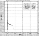
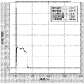
製剤用量の大部分が無針注射器から送達される間の一定した、またはゆっくりと変化する製剤圧力(図2を参照されたい)。本発明の好ましい態様において、望ましい注射は皮下注射である。一般的に、これは、送達される注射剤が通る穴が形成される、前の高圧段階(「穿刺段階」を参照されたい)を必要とする。
Delivery stage:
Constant or slowly changing formulation pressure while the majority of the formulation dose is delivered from a needleless syringe (see FIG. 2). In a preferred embodiment of the invention, the desired injection is a subcutaneous injection. In general, this requires a previous high-pressure stage (see “Puncture Stage”) in which a hole is formed through which the injection to be delivered passes.
デポー注射、デポーなど:
長期間にわたって一定して活性化合物を放出する、薬理学的薬剤の注射、通常、皮下注射、静脈内注射、または筋肉内注射。デポー注射は、ある特定の形の薬物、例えば、デカン酸塩またはデカン酸エステルとして利用できることがある。デポー注射の例には、Depo Proveraおよびデカン酸ハロペリドールが含まれる。デポーは体内の一カ所に局在してもよいが、常に体内の一カ所に局在しているとは限らない。
Depot injection, depot etc:
Injection of a pharmacological agent, usually subcutaneous, intravenous, or intramuscular, that releases the active compound constantly over a long period of time. Depot injections may be available as certain forms of drugs, such as decanoate or decanoate. Examples of depot injections include Depo Provera and haloperidol decanoate. The depot may be localized in one place in the body, but is not always localized in one place in the body.
DosePro、Intraject、‘086システムなど:
現在、Zogenix社によって製造されている、1回使用の、予め充填された、使い捨ての無針注射器。カートリッジには、対象に注射される液体が予め充填されている。カートリッジは、液体出口、および液体と接触している自由ピストンを有する。この注射器は、圧縮ガスばねによって駆り立てられ、装置が駆動されるまで一時的に拘束される衝撃部材を備えるエナージャイザーを備える。衝撃部材は、ばねの力によって第1の方向に動いて、最初に自由ピストンにぶつかり、次いで、ピストンを第1の方向に動かし続けて、ある用量の液体を液体出口に通して放出する。ばねは内蔵のエネルギーストア(energy store)を提供し、高エネルギー状態から低エネルギー状態に動くが、その逆はできないように適合されている。エナージャイザーは、装置が皮膚に押しつけられた時にだけ装置を駆動する、従って、注射を開始するトリガー手段を備えてもよい。DoseProの要素および変形物は米国特許第5,891,086号(‘086)に記載されており、さらなる説明、改善、および変形は、参照により本明細書に組み入れられる、US6620135、US6554818、US6415631、US6409032、US6280410、US6258059、US6251091、US6216493、US6179583、US6174304、US6149625、US6135979、US5957886、US5891086、およびUS5480381において見られる。
DosePro, Intraject, '086 system, etc .:
A single-use, pre-filled, disposable needle-free syringe currently manufactured by Zogenix. The cartridge is prefilled with a liquid to be injected into the subject. The cartridge has a liquid outlet and a free piston in contact with the liquid. The syringe includes an energizer with an impact member that is driven by a compressed gas spring and is temporarily restrained until the device is driven. The impact member moves in the first direction by the force of the spring, first hits the free piston, and then continues to move the piston in the first direction to release a dose of liquid through the liquid outlet. The spring provides a built-in energy store and is adapted to move from a high energy state to a low energy state, but not vice versa. The energizer may be provided with trigger means that drives the device only when the device is pressed against the skin and thus initiates an injection. Elements and variations of DosePro are described in U.S. Pat.No. 5,891,086 ('086), further description, improvements, and variations are incorporated herein by reference, US6620135, US6554818, US6415631, US64090310, US6280410, Seen in US6258059, US6251091, US6216493, US6179583, US6174304, US6149625, US6135979, US5957886, US5891086, and US5480381.
エナージャイザー:
注射のためにエネルギーを供給し、装置を起動し、送達中の適切な圧力プロファイルを確かなものにする自動注入装置の機械部分。エナージャイザーは、送達前に設けなければならない安全機構を備えてもよい。一部の先行技術では、この部分はアクチュエータと呼ばれることに注意のこと。しかしながら、ここでは、本発明者らは、例えば、安全機構アクチュエータとの混同を避けるために、この部分をエナージャイザーと呼ぶ。
Energizer:
The mechanical part of an automatic infusion device that provides energy for injection, activates the device, and ensures the proper pressure profile during delivery. The energizer may be equipped with a safety mechanism that must be provided prior to delivery. Note that in some prior art, this part is called an actuator. However, here we call this part an energizer to avoid confusion with, for example, a safety mechanism actuator.
賦形剤:
混合物が、活性薬物の効果的な送達に必要な適切な物理的特徴を得るように活性原薬に加えられる、担体を含む任意の物質。
Excipient:
Any substance, including a carrier, to which the mixture is added to the active drug substance so as to obtain the appropriate physical characteristics necessary for effective delivery of the active drug.
濾紙重量、すなわちFPW:
無針注射事象後に皮膚に残された注射剤の量の尺度。FPWを測定するために、注射されなかった材料を濾紙に吸い取り、試料を秤量し、風袋を差し引く。血液が試料中に見られれば、このことに注意する。血液はFPWの過大評価を引き起こすので、一般的に、結果は用いられない。VASを補正するためにFPWを使用することができる。VASの定義および実施例1を参照されたい。
Filter paper weight, i.e.FPW:
A measure of the amount of injection left on the skin after a needleless injection event. To measure FPW, blot the uninjected material onto filter paper, weigh the sample, and subtract the tare. Note this if blood is found in the sample. In general, results are not used because blood causes overestimation of FPW. FPW can be used to compensate for VAS. See VAS definition and Example 1.
製剤、注射剤など:
注射することができる任意の液体、固体、または他の状態の物体。好ましい製剤は、溶液、ナノ懸濁液を含む懸濁液、エマルジョン、ポリマー、およびゲルを含むが、それらに限定されない液体製剤である。製剤には、注射に適した賦形剤を含有し、1種類または複数の種類の活性薬学的成分を含有する製剤が含まれるが、それらに限定されない。
Formulations, injections, etc .:
Any liquid, solid, or other state object that can be injected. Preferred formulations are liquid formulations including but not limited to solutions, suspensions including nanosuspensions, emulsions, polymers, and gels. Formulations include, but are not limited to, formulations containing excipients suitable for injection and containing one or more types of active pharmaceutical ingredients.
円錐台形:
土台に平行な面によって先端部が切断されている円錐の形状を有すること。皿ばねを参照されたい
Frustoconical:
Having a conical shape where the tip is cut by a plane parallel to the base. Please refer to the disc spring
密封封止容器など:
閉じ込められたガスの漏出を通さない、無針注射の動力源として用いられる加圧ガス用の容器。一般的に、密封封止容器は深絞り亜鉛メッキ鋼から形成され、加圧ガス、例えば、窒素、または液化ガス、例えば、二酸化炭素もしくは亜酸化窒素を含有する。密封封止容器は、ソーダ水またはホイップクリームなどの調製食品のために食品サービス産業において用いられることが多いが、エアゾール吸入(US6,981,660を参照されたい)または無針注射(us3.10.US6607510を参照されたい)などの分野において医療用途にも供される。通常、これらの容器には、加圧内容物を利用できるようにするために穴を開けるように設計された特徴がある。
Sealed sealed container etc .:
A container for pressurized gas used as a power source for needle-free injection that does not allow leakage of trapped gas. Generally, hermetically sealed containers are formed from deep drawn galvanized steel and contain a pressurized gas, such as nitrogen, or a liquefied gas, such as carbon dioxide or nitrous oxide. Sealed sealed containers are often used in the food service industry for prepared foods such as soda water or whipped cream, but aerosol inhalation (see US 6,981,660) or needle-free injection (us3.10.US6607510 For medical use in fields such as Typically, these containers have features designed to be pierced so that pressurized content can be used.
免疫原性:
物質(抗原)が免疫応答を誘発する能力。非凝集分子が免疫原性でない時でも、凝集した生物製剤薬物が免疫原性になる場合がある。
Immunogenicity:
The ability of a substance (antigen) to elicit an immune response. Aggregated biopharmaceutical drugs may become immunogenic even when non-aggregated molecules are not immunogenic.
衝撃ギャップなど:
製剤の圧力スパイクを作り出すために用いられる、衝撃部材(ラムを参照されたい)とピストンとのギャップの幅。無針送達事象の間、衝撃部材は、例えば、圧縮ガスまたは別のエネルギー源によって、ギャップの端から端まで駆り立てられる。ここで、衝撃部材はギャップの端から端まで移動する時に、エネルギー源によってなされた仕事を統合し、衝突時に、このエネルギーを製剤に送達して、初期圧力スパイクを作り出す。「穿刺段階」も参照されたい。
Impact gap etc:
The width of the gap between the impact member (see Ram) and the piston used to create the pressure spike of the formulation. During a needle-free delivery event, the impact member is driven from end to end, for example, by compressed gas or another energy source. Here, as the impact member moves from end to end of the gap, it integrates the work done by the energy source and delivers this energy to the formulation upon impact, creating an initial pressure spike. See also “Puncture Stage”.
インビボ(「生物内の」というラテン語から):
部分的な生物もしくは死んだ生物またはインビトロ実験とは対照的に、生物全体を用いた実験。インビボ研究には動物試験およびヒト臨床試験が含まれる。インビボ試験は、結果が臨床結果をインビトロ実験より予測し得るのでインビトロ試験より好ましいことが多い。
In vivo (from the Latin word “in vivo”):
Experiments with whole organisms as opposed to partial or dead organisms or in vitro experiments. In vivo studies include animal studies and human clinical studies. In vivo tests are often preferred over in vitro tests because the results can predict clinical outcomes from in vitro experiments.
インビトロ(「ガラス内の」というラテン語から):
生物(インビボを参照されたい)ではないが、管理された環境、例えば、試験管または他の研究室実験器具の中での処置。インビトロ試験は、コスト、ならびにヒトおよび/または動物対象に対する危険性が低いためにインビボ試験より好ましいことが多い。
In vitro (from the Latin word "in glass"):
Treatment in a controlled environment, such as a test tube or other laboratory labware, but not an organism (see in vivo). In vitro testing is often preferred over in vivo testing because of its cost and low risk to human and / or animal subjects.
インビボ/インビトロ相関、IVIVCなど:
インビトロ測定値、設計パラメータなどに基づいてインビボ性能を予測するモデル、好ましくは、数学モデル。予測IVIVCは、高価な、かつ潜在的に危険なヒト臨床試験または動物臨床試験を必要とすることなくインビボ測定値の予測値を可能にする。IVIVCは、好ましくは、薬物、薬物送達技術、または他の医療機器技術の様々な構成を用いた、いくつかの臨床試験、好ましくはヒト試験のメタアナリシスに基づく。この議論のために、IVIVCは、注射器設計パラメータおよび性能のベンチ測定値に基づいて無針注射器のインビボ注射性能を予測するモデルを意味するとみなすことができる。
In vivo / in vitro correlation, IVIVC etc .:
A model, preferably a mathematical model, that predicts in vivo performance based on in vitro measurements, design parameters, and the like. Predictive IVIVC enables predictive values of in vivo measurements without the need for expensive and potentially dangerous human or animal clinical trials. IVIVC is preferably based on a meta-analysis of several clinical trials, preferably human trials, using various configurations of drugs, drug delivery technologies, or other medical device technologies. For the purposes of this discussion, IVIVC can be considered to mean a model that predicts the in vivo injection performance of a needleless syringe based on syringe design parameters and performance bench measurements.
噴流試験、噴流試験器、噴流試験法など:
模擬薬物送達事象の間に液体噴流が当たった時にトランスデューサーにかかる力を測定する実験器具。これらのデータを用いると、ある期間にわたる製剤圧力を計算することができる。噴流試験はひずみゲージ試験と同時に行われることが多い。
Jet test, jet tester, jet test method, etc .:
A laboratory instrument that measures the force on a transducer when a liquid jet strikes during a simulated drug delivery event. Using these data, the formulation pressure over a period of time can be calculated. The jet test is often performed simultaneously with the strain gauge test.
無針注射器、ニードルレス(Needle-less)注射器、噴流注射器など:
皮下針を用いることなく皮下注射、筋肉内注射、または皮内注射を送達する薬物送達システム。注射は、皮膚、皮下組織、または筋肉に望ましい深さまで入り込むのに十分な速度で、少なくとも1つの高速液体噴流を作り出すことによって達成される。無針注射システムには、Zogenix Corporationにより製造されたDosePro(登録商標)システム、Bioject Medical Technologies, Incorporatedにより製造されたBioject(登録商標)2000、Iject、またはVitaject装置、Antaresにより製造されたMediject VISIONおよびMediject VALEO装置、Visionary Medicalにより製造されたPenJet装置、Crossjectにより製造されたCrossJect装置、Biovalveにより製造されたMiniJect装置、Caretek Medicalにより製造されたImplaject装置、AlgoRxにより製造されたPowderJect装置、National Medical Productsにより製造されたJ-tip装置、Activa Systemsにより製造されたAdvantaJet、Injex-Equidyneにより製造されたInjex30装置、およびMedical House Productsにより製造されたMhi-500装置が含まれるが、それらに限定されない。
Needleless syringe, needle-less syringe, jet syringe, etc .:
A drug delivery system that delivers subcutaneous, intramuscular, or intradermal injection without the use of a hypodermic needle. Injection is accomplished by creating at least one high velocity liquid jet at a rate sufficient to penetrate the skin, subcutaneous tissue, or muscle to the desired depth. Needleless injection systems include the DosePro® system manufactured by Zogenix Corporation, the Bioject® 2000, Iject, or Vitaject device manufactured by Bioject Medical Technologies, Incorporated, the Mediject VISION manufactured by Antares, and Mediject VALEO device, PenJet device manufactured by Visionary Medical, CrossJect device manufactured by Crossject, MiniJect device manufactured by Biovalve, Implaject device manufactured by Caretek Medical, PowderJect device manufactured by AlgoRx, by National Medical Products These include, but are not limited to, J-tip devices manufactured, AdvantaJet manufactured by Activa Systems, Injex30 devices manufactured by Injex-Equidyne, and Mhi-500 devices manufactured by Medical House Products.
ピストン:
エネルギー源からの力によって、オリフィスから液体製剤を排出して無針注射を実現する無針注射器の構成要素。好ましい態様において、無針注射器には製剤が予め充填され、次いで、ピストンは容器閉鎖システムの薬物接触面になる。特に好ましい態様において、ピストンは、衝撃部材からのエネルギーを製剤に伝えて圧力スパイクを作り出すというさらなる機能を有する。「穿刺段階」を参照されたい。好ましくは、ピストンはPTFEからなる。
piston:
A component of a needleless syringe that realizes needleless injection by discharging a liquid preparation from an orifice by a force from an energy source. In a preferred embodiment, the needleless syringe is pre-filled with the formulation and then the piston becomes the drug contacting surface of the container closure system. In a particularly preferred embodiment, the piston has the additional function of transferring energy from the impact member to the formulation to create a pressure spike. See “Puncture Stage”. Preferably, the piston is made of PTFE.
ポリテトラフルオロエチレン、PTFE、Teflonなど:
テトラフルオロエチレンの合成フルオロポリマー。PTFEはDuPontの商標名であるTeflonによって最も知られている。PTFEは、完全に炭素およびフッ素からなる高分子量フルオロカーボン固体である。PTFEは、固体に対して最も低い摩擦係数の1つを有する。PTFEはまた、多くの薬物製剤のための許容可能な薬物接触面であることも示されている。
Polytetrafluoroethylene, PTFE, Teflon etc .:
Synthetic fluoropolymer of tetrafluoroethylene. PTFE is best known by Teflon, the DuPont trade name. PTFE is a high molecular weight fluorocarbon solid consisting entirely of carbon and fluorine. PTFE has one of the lowest friction coefficients for solids. PTFE has also been shown to be an acceptable drug contact surface for many drug formulations.
予防:
有害な状態または医学的障害の発生または発症を阻止するために用いられる薬物の投与。
Prevention:
Administration of drugs used to prevent the development or development of adverse conditions or medical disorders.
穿刺段階、初期圧力スパイクなど:
皮膚の中に入って、または皮膚を通って望ましい深さまで穿孔するのに十分なエネルギーを有する噴流を作り出す、無針注射器の中の製剤圧力の初期スパイク(図12、図13、および図15を参照されたい)。本発明の好ましい態様において、注射は皮下注射である。効率的な再現性のある皮下注射を実現するために、噴流は、皮下組織まで穿孔するのに十分なエネルギーがあることが重要である。しかしながら、注射が、痛みを伴う筋肉内注射になる前に穴の形成を止めるために、製剤の大部分が低圧で送達されることが次に重要である。
Puncture stage, initial pressure spike, etc .:
An initial spike of formulation pressure in a needleless syringe (Figures 12, 13, and 15) that creates a jet with sufficient energy to penetrate into or through the skin to the desired depth. See) In a preferred embodiment of the invention, the injection is a subcutaneous injection. In order to achieve an efficient and reproducible subcutaneous injection, it is important that the jet has sufficient energy to drill into the subcutaneous tissue. However, it is next important that the majority of the formulation is delivered at low pressure to stop the formation of holes before the injection becomes a painful intramuscular injection.
ラム、衝撃部材など:
圧力に曝露された時に、前方に、空気間隙(「衝撃ギャップ」を参照されたい)の端から端まで駆り立てられた後に、薬物送達ピストンにぶつかる構成要素。ラムが衝撃ギャップを横断した時に膨張ガスによってなされる仕事は本質的に全て、ラムがピストンにぶつかった時に製剤に送達され、皮膚に、望ましい深さ、例えば、皮下組織まで穴を作り出す圧力スパイク(「穿刺段階」を参照されたい)を作り出す。次いで、加圧ガスはラムおよびピストンを前方に動かし、製剤を穴に通して望ましい組織の中に送達する。
Ram, impact member, etc .:
A component that, when exposed to pressure, strikes the drug delivery piston after being propelled forward to end of the air gap (see “Shock Gap”). Essentially all the work done by the inflation gas when the ram crosses the impact gap is delivered to the formulation when the ram strikes the piston, creating a pressure spike in the skin that creates a hole to the desired depth, e.g., subcutaneous tissue ( (See “Puncture Stage”). The pressurized gas then moves the ram and piston forward, delivering the formulation through the hole and into the desired tissue.
弾力性の:
曲げられた、圧縮された、または引き伸ばされた後に元の形または位置に戻ること。
Elasticity:
To return to its original shape or position after being bent, compressed, or stretched.
比重:
水密度に対する化合物密度の割合。
specific gravity:
Ratio of compound density to water density.
スプールバルブ:
無針注射器の加圧ガス動力源の圧力がガスブロッキング構成要素を前方に駆り立てるが、ガスブロッキング構成要素の動きがさらなる装置要素によって阻害される、バルブ。さらなる装置構成要素が取り外された時に、好ましくは、無針注射器が患者の皮膚に押しつけられた時、さらなる装置構成要素の相対的運動のために、さらなる装置構成要素が取り外された時に、ガスブロッキング構成要素が前方に動かされて、加圧ガスが薬物送達機構に流入するのを可能にするガス出口が露出し、それによって薬物が送達される。1つの態様である「平衡スプールバルブ」では、ガスブロッキング構成要素の基端および末端は動力源圧力に曝露され、異なる面積の表面を加圧ガスに曝露する。これによって、駆動力は調整され、場合によっては、ガスブロッキング構成要素の動きをブロックする、さらなる装置構成要素上での摩擦力が最適化および/または最小化される。
Spool valve:
A valve, wherein the pressure of the pressurized gas power source of the needleless syringe drives the gas blocking component forward, but the movement of the gas blocking component is impeded by additional device elements. Gas blocking when the additional device component is removed, preferably when the needleless syringe is pressed against the patient's skin, when the additional device component is removed due to the relative movement of the additional device component. The component is moved forward to expose a gas outlet that allows pressurized gas to flow into the drug delivery mechanism, thereby delivering the drug. In one embodiment, an “equilibrium spool valve”, the proximal and distal ends of the gas blocking component are exposed to power source pressure and different areas of the surface are exposed to pressurized gas. This adjusts the driving force and, in some cases, optimizes and / or minimizes frictional forces on further device components that block the movement of the gas blocking component.
ばね:
注射器内で医用薬剤を推進させて、患者の皮膚の中に入れ、皮膚を通過し、体内に入れることに使用するためのエネルギーを保存することができる機構。エネルギーストアによって供給される力は変位量に比例する。この機構は機械式でもよく、例えば、圧縮可能な金属構成要素、例えば、コイルばねまたは皿ばねスタックでもよい。好ましくは、機構は、エネルギーが保存されており、放出されるとガスが膨張する圧縮ガスばねである。
Spring:
A mechanism that can store energy for use in propelling a medicinal agent in a syringe, into the patient's skin, through the skin, and into the body. The force supplied by the energy store is proportional to the amount of displacement. This mechanism may be mechanical, for example a compressible metal component, for example a coil spring or a disc spring stack. Preferably, the mechanism is a compressed gas spring in which energy is stored and the gas expands when released.
剛性の:
高弾性率または低圧縮率を有すること。この場合、衝撃エネルギーを効果的に媒体に通して伝えることができる材料。
Of rigidity:
Have high modulus or low compressibility. In this case, a material that can effectively transmit impact energy through the medium.
ひずみゲージ試験、ひずみゲージ法など:
インビトロ送達事象中に製剤圧力を測定する方法。ひずみゲージは製剤容器に取り付けられ、製剤圧力について較正され、次いで、ある期間にわたって製剤の圧力プロファイルを測定するのに用いられる。ひずみゲージ試験は一般的に噴流試験と並行して行われる。
Strain gauge test, strain gauge method, etc .:
A method of measuring formulation pressure during an in vitro delivery event. A strain gauge is attached to the formulation container, calibrated for formulation pressure, and then used to measure the pressure profile of the formulation over a period of time. The strain gauge test is generally performed in parallel with the jet test.
皮下組織(subcutaneous tissue)、皮下組織(stratum subcutaneum)、皮下組織(hypodermis)、皮下組織(hypoderm)、または浅在筋膜など:
主に、緩い結合組織および脂肪の小葉からなる、皮膚の真皮のすぐ下にある組織層。皮下組織は皮下注射の標的である。
Subcutaneous tissue, subcutaneous tissue (stratum subcutaneum), subcutaneous tissue (hypodermis), subcutaneous tissue (hypoderm), or superficial fascia:
A tissue layer just below the dermis of the skin, mainly consisting of loose connective tissue and fat leaflets. Subcutaneous tissue is the target for subcutaneous injection.
視覚評価スコア(Visual Assessment Score)、VASなど:
観察に基づいて0〜4のスケールで無針注射をスコアリングする半定量法。0、1、または2とスコアリングされた注射は失敗と呼ばれるのに対して(以下の「ウェットインジェクション(wet injection)」を参照されたい)、3または4は成功した注射である。注射スコアは以下の通り定義される:
0=注射剤は100%はね返され、表皮に穴さえない。
1=表皮に穴があるが、注射剤の浸透があったとしても、ごくわずかである。
2=注射剤の一部の浸透(約5%〜<90%)
3=注射剤の約90%〜<95%の浸透
4=注射剤の約95%の浸透
Visual assessment score, VAS, etc .:
Semi-quantitative method of scoring needleless injections on a scale of 0-4 based on observations. Injections scored as 0, 1, or 2 are referred to as failures (see “wet injection” below), whereas 3 or 4 are successful injections. The injection score is defined as follows:
0 = Injection is rebounded 100% and there are no holes in the epidermis.
1 = There is a hole in the epidermis, but very little, if any, of the injection.
2 = Partial penetration of injection (approximately 5% to <90%)
3 = About 90% to <95% penetration of injection
4 = About 95% penetration of injection
水蒸気透過率(WVTR)は、水蒸気が材料を透過する定常状態での率である。値はUS標準単位ではg/100in2/24hr、メートル単位ではg/m2/24hrで表される。 The water vapor transmission rate (WVTR) is a rate in a steady state where water vapor passes through the material. Values US The standard unit g / 100in 2 / 24hr, the meters are represented by g / m 2 / 24hr.
ウェットインジェクション:
注射剤の10%超が皮下組織に入り込まない、失敗した無針注射。関連する定義は、視覚評価スコア(VAS)が3未満の注射である。
Wet injection:
Unsuccessful needleless injection in which more than 10% of the injection does not enter the subcutaneous tissue. A related definition is an injection with a visual assessment score (VAS) of less than 3.
一般的な発明
本発明は、信頼性、安全性、および製造性を改善する、予め充填された無針注射器に対する改善に関する。
General Invention The present invention relates to improvements to prefilled needleless syringes that improve reliability, safety, and manufacturability.
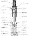
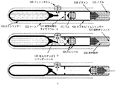
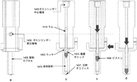
本発明の1つの態様を図1に示した。この態様には、先行技術装置を上回る多くの改善がある。 One embodiment of the present invention is shown in FIG. This aspect has many improvements over prior art devices.
改善の1つがガスシリンダー20に対するものである。他の装置と比較して、ガスシリンダー20は直径が大きく、深く絞りがなされていない。このため体積が大きく、従って、送達が進んだ時に圧力変化が小さい。同時に、例えば、‘086に記載の装置の中にあるガスシリンダーより深く絞りがなされていないので製造しやすい。好ましくは、ガスシリンダー20は深絞りされたアルミニウムであるが、衝撃押出し、ダイカスト、または機械加工を含むが、それらに限定されない他の製作技法が用いられてもよい。図1に示したように、ガスシリンダー20およびバルブブロック19は別個の構成要素でもよいが、おそらく深絞りと組み合わされる機械加工を用いて、これらを組み合わせることが望ましい場合がある。 One improvement is over the gas cylinder 20. Compared to other devices, the gas cylinder 20 has a large diameter and is not deeply drawn. This results in a large volume and therefore a small pressure change as delivery progresses. At the same time, for example, it is easier to manufacture because it is not drawn deeper than the gas cylinder in the device described in '086. Preferably, the gas cylinder 20 is deep drawn aluminum, but other fabrication techniques may be used including but not limited to impact extrusion, die casting, or machining. As shown in FIG. 1, the gas cylinder 20 and valve block 19 may be separate components, but it may be desirable to combine them, possibly using machining combined with deep drawing.
ガスシリンダー20の中のガスは保存中は封じ込められ、スプールバルブ21によって装置起動の際に放出される。一部の先行技術装置とは異なり、スプールバルブ21は、ガスシリンダー20の中のガスの圧力を無針注射を引き起こすのに必要とされるエネルギーに変換する、この態様ではラム12である構成要素とは機能上に異なる。これにより、加圧ガスに曝露される面積に大きな違いがあるために、保存中にスプールバルブ21が受ける力を、保存中に加圧ガスに曝露された時にラム12が受ける力よりかなり小さくすることが可能になる。これにより変形およびクリープの可能性が著しく最小化し、それによって、時期尚早な発射または発射の欠如の可能性が小さくなる。これらの問題は、保存中に見られる高温または加速した薬学的安定性によって悪化することがある。本発明のこの局面は、これらの問題を克服する装置プライミング工程の潜在的な必要を無くすことができる。 The gas in the gas cylinder 20 is confined during storage and released by the spool valve 21 when the apparatus is started. Unlike some prior art devices, the spool valve 21 is a component that in this embodiment is a ram 12 that converts the pressure of the gas in the gas cylinder 20 into the energy required to cause a needleless injection. And functionally different. This makes the force experienced by the spool valve 21 during storage significantly less than the force experienced by the ram 12 when exposed to pressurized gas during storage due to the large difference in the area exposed to the pressurized gas. It becomes possible. This significantly minimizes the possibility of deformation and creep, thereby reducing the possibility of premature firing or lack of firing. These problems can be exacerbated by the high temperatures or accelerated pharmaceutical stability found during storage. This aspect of the present invention can eliminate the potential need for a device priming process that overcomes these problems.
スプールバルブ21の機能は以下の通りである。装置がそのケース(図示せず)によって保持され、注射オリフィス27が患者の皮膚の目的の注射部位に押しつけられた時に、摺動体15は下向きに動く。これによって、スプール17はスプール保持ケージ18に曝露され、次に、図1に示したように、スプール17は左側に動くことが可能になる。これによって、バルブブロック19の底部にあるガス出口22が、バルブブロック19の上部にあるガス入口23を介してガスシリンダー20から出た加圧ガスに曝露される。これによって、ガスはラムヘッド14へ移動し、ラムヘッド14に衝突する力を作り出す。 The function of the spool valve 21 is as follows. When the device is held by its case (not shown) and the injection orifice 27 is pressed against the intended injection site on the patient's skin, the slide 15 moves downward. This exposes the spool 17 to the spool holding cage 18, which in turn allows the spool 17 to move to the left as shown in FIG. As a result, the gas outlet 22 at the bottom of the valve block 19 is exposed to the pressurized gas exiting from the gas cylinder 20 via the gas inlet 23 at the top of the valve block 19. This causes the gas to move to the ram head 14 and create a force that impacts the ram head 14.
バルブブロック19は、好ましくは、機械加工されたアルミニウムであるが、ダイカストを含むが、それらに限定されない方法によって作られてもよく、ガスシリンダー20および/またはラムシリンダー13と組み合わされてもよい。 The valve block 19 is preferably machined aluminum, but may be made by methods including but not limited to die casting and may be combined with the gas cylinder 20 and / or the ram cylinder 13.
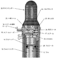
先行技術装置、例えば、US6607510(‘510)に記載の先行技術装置は、ガスを放出するためにカートリッジを穿刺要素で突き刺すことによって装置が「プライミング」される密封封止ガスカートリッジを有する。‘510に開示された発明では、オリフィスキャップが取り外され、次いで、装置の反対の端にまわしてはめられて、密封封止ガスカートリッジは穿刺要素に押しつけられる。従って、いかなるさらなるバルブ構成要素も完璧なシール、例えば、Oリングシールを必要とせず、このようなシールは‘510に開示されない。しかしながら、本明細書に記載の態様では、スプールバルブは、保存中に加圧ガスを漏出させない、従って、スプール17において、さらなるシーリング要素24および25(図2を参照されたい)を必要とする一次シールである。これらのシーリング要素24および25はOリングまたはシーリンググリースでもよいが、それらに限定されず、好ましくは、スプール17の上にオーバーモールドされるか、または、永久シール24に必要な条件が、送達中に最大で数百ミリ秒間だけ圧力を保持しなければならない一時シール25より厳密性が高いことであるので、潜在的にはそれぞれのタイプの1つのシールである。スプール17は、好ましくは、機械加工された真鍮であるが、他の金属またはポリマーを含むが、それらに限定されない他の材料が用いられてもよく、射出成形またはダイカストを含むが、それらに限定されない他の製作方法が用いられてもよい。 Prior art devices, for example the prior art device described in US6607510 ('510), have a hermetically sealed gas cartridge in which the device is "primed" by piercing the cartridge with a piercing element to release gas. In the invention disclosed in '510, the orifice cap is removed and then fitted over the opposite end of the device to push the hermetically sealed gas cartridge against the piercing element. Thus, no further valve components require a perfect seal, such as an O-ring seal, and such a seal is not disclosed in '510. However, in the embodiment described herein, the spool valve does not leak pressurized gas during storage, and therefore requires a primary sealing element 24 and 25 (see FIG. 2) in the spool 17. It is a seal. These sealing elements 24 and 25 may be O-rings or sealing greases, but are not limited thereto and are preferably overmolded on the spool 17 or the conditions required for the permanent seal 24 during delivery This is potentially one seal of each type, because it is more stringent than the temporary seal 25, which must hold the pressure for up to several hundred milliseconds. The spool 17 is preferably machined brass, but other materials may be used including but not limited to other metals or polymers, including but not limited to injection molding or die casting. Other fabrication methods that are not possible may be used.
スプール保持ケージ18は、好ましくは、スタンピングされているが、あるいは、ダイカストまたは射出成形されたポリマーまたは金属が含まれるが、それらに限定されない。 The spool retaining cage 18 is preferably stamped or alternatively includes, but is not limited to, die cast or injection molded polymer or metal.
‘086に記載の装置ではラムは直円柱である。ラムおよび垂直線の詳細は前記に説明されている。これは、一定の、かつ比較的小さな断面積のラムであるので、望ましい製剤圧力および穿刺段階圧力を作り出すために必要とされるガス圧力は極めて大きく、そのため、構成要素の変形およびガス漏出の周りに問題が生じる。ガス圧力を小さくするために、図1に示した本発明の態様において、加圧ガスはラムヘッド14を介してラム12に導入される。ラムヘッド14はラム12より著しく大きな直径を有する。図1および図2を参照されたい。これにより、かなり低いガス圧力で穿刺段階および送達段階に必要とされる力を実現しながら、ラム12の長さ、直径、および質量をラムガイド11の中での誘導のために最適化し、カプセル6の中でのピストン8の望ましい移動と望ましい穿刺段階圧力に必要とされる衝撃ギャップに合わせることが可能になる。ラムヘッド14は、Oリングまたはオーバーモールドシールを含むが、それらに限定されないシーリング法を用いて、ラムシール26を介してラムシリンダー13の内側に密閉される。Oリングシールに好ましい材料は、PTFE、ニトリル、またはFEPでコーティングされたシリコーンである。または、ラムシール26は、自転車の空気入れに似た、一方向バルブまたは「チェックバルブ」としてトップラムヘッド14に取り付けられたディスクまたはワッシャーであり得る。これは、ラムヘッド14を通り過ぎて充填する可能性を許すだろう。 In the device described in '086, the ram is a right circular cylinder. Details of the ram and vertical lines are described above. Since this is a constant and relatively small cross-sectional ram, the gas pressure required to create the desired formulation pressure and puncture stage pressure is very high, so around component deformation and gas leakage Problems arise. In order to reduce the gas pressure, in the embodiment of the invention shown in FIG. 1, pressurized gas is introduced into the ram 12 via the ram head 14. The ram head 14 has a significantly larger diameter than the ram 12. See FIG. 1 and FIG. This optimizes the length, diameter, and mass of the ram 12 for guidance within the ram guide 11 while achieving the force required for the puncture and delivery phases at a fairly low gas pressure, It is possible to match the impact gap required for the desired movement of the piston 8 in 6 and the desired puncture stage pressure. The ram head 14 is sealed inside the ram cylinder 13 via a ram seal 26 using a sealing method including but not limited to an O-ring or overmold seal. A preferred material for the O-ring seal is PTFE, nitrile, or silicone coated with FEP. Alternatively, the ram seal 26 may be a disc or washer attached to the top ram head 14 as a one-way valve or “check valve”, similar to a bicycle inflator. This would allow the possibility of filling past the ram head 14.
ラム12およびラムヘッド14は、好ましくは、一片のアルミニウムから機械加工されるが、別個の部品から機械加工された冷間成形された一片、ダイカスト製のマグネシウムもしくは亜鉛、または機械加工された軸の上にあるオーバーモールドポリマーヘッドでもよい。好ましくは、加圧ガスが充填された後、漏出がチェックされた後、ラムシリンダー13がバルブブロック19に取り付けられた後に、ラム12はラムガイド11に挿入されるが、ラムシール26が一方向バルブであるならば充填前に組み立てられてもよく、ラムシリンダー13がバルブブロック19に取り付けられる前にラムシリンダー13に挿入されてもよい。 The ram 12 and ram head 14 are preferably machined from a piece of aluminum, but are cold formed pieces machined from separate parts, die cast magnesium or zinc, or machined shafts. May be an overmolded polymer head. Preferably, after filling with pressurized gas, after checking for leaks, after the ram cylinder 13 is mounted on the valve block 19, the ram 12 is inserted into the ram guide 11, but the ram seal 26 is a one-way valve. If so, it may be assembled prior to filling, and may be inserted into the ram cylinder 13 before the ram cylinder 13 is attached to the valve block 19.
必要とされる衝撃ギャップを維持するように組み立てられた時に、ラム12が所定の位置にとどまるように、ラム12は、加圧ガスの力の下で壊れる特徴によって保持されなければならないか、または取扱いおよび保存の間にラム12を保持するのに十分な強さがあるが、ラムヘッド14に加わっている加圧ガスの力と比較して小さな摩擦力によって所定の位置に保持されなければならない。図1に示した、この1つの態様は、ラムヘッド14に対する加圧ガスの力によって破壊するシヤーピン52である。関連する解決策は、摩擦嵌合を介してラムガイド11の中に取り付けられた、スタンピングまたはエッチングされたクラッシュディスク(crush disk)であろう。さらなる解決策には、ラムガイド11に取り付けられたオーバーモールドポリマー部品または摩擦嵌合ポリマー部品が含まれる。 The ram 12 must be held by features that break under the force of pressurized gas, so that the ram 12 remains in place when assembled to maintain the required impact gap, or Although strong enough to hold the ram 12 during handling and storage, it must be held in place by a small frictional force compared to the force of the pressurized gas applied to the ram head 14. One embodiment shown in FIG. 1 is a shear pin 52 that breaks by the force of pressurized gas against the ram head 14. A related solution would be a stamped or etched crush disk mounted in the ram guide 11 via a friction fit. Further solutions include overmolded polymer parts or friction-fit polymer parts attached to the ram guide 11.
ラムガイド11は、好ましくは、亜鉛またはアルミニウムのダイカストであるが、他の解決策には、射出成形されたポリマーもしくは金属または機械加工されたスチールまたはアルミニウムが含まれるが、それらに限定されない。ラムヘッド14はラムシリンダー13によって誘導され、好ましくは、ラムシリンダー13はストックチューブから製作されるが、他の解決策には、深絞りもしくは衝撃押出し、射出成形ポリマー、バルブブロック19の一部としての機械加工を含む機械加工、ダイカスト、または押出しが含まれるが、それらに限定されない。好ましくは、ラムシリンダー13は、バルブブロック19に溶接され、圧着リング10でラムガイド11に取り付けられた、スエージ加工された末端を有するストックチューブである。代替には、ラムガイド11への溶接および/またはバルブブロック19への圧着が含まれるが、それらに限定されない。 The ram guide 11 is preferably a zinc or aluminum die cast, but other solutions include, but are not limited to, injection molded polymer or metal or machined steel or aluminum. The ram head 14 is guided by a ram cylinder 13, preferably the ram cylinder 13 is made from stock tube, but other solutions include deep drawing or impact extrusion, injection molding polymer, part of valve block 19 This includes but is not limited to machining, including machining, die casting, or extrusion. Preferably, the ram cylinder 13 is a stock tube having a swaged end that is welded to the valve block 19 and attached to the ram guide 11 with a crimp ring 10. Alternatives include, but are not limited to, welding to ram guide 11 and / or crimping to valve block 19.
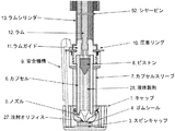
ラム12は、ピストン8にぶつかり、次いで、ピストン8を動かして、ピストン8、カプセル6、ノズル5、およびゴムシール4によって画定および閉鎖された薬物容器の中に閉じ込められた液体薬物製剤28を送達するようにラムガイド11によって誘導される。カプセル6はカプセルスリーブ7によって補強される。カプセルスリーブ7はまた、本発明の態様においてカプセル6と接触してノズル5を保持するのに役立つ。図1に示したように、ノズル5は別個の部分である。 The ram 12 hits the piston 8 and then moves the piston 8 to deliver a liquid drug formulation 28 confined in a drug container defined and closed by the piston 8, capsule 6, nozzle 5, and rubber seal 4. So as to be guided by the ram guide 11. The capsule 6 is reinforced by a capsule sleeve 7. The capsule sleeve 7 also serves to hold the nozzle 5 in contact with the capsule 6 in embodiments of the invention. As shown in FIG. 1, the nozzle 5 is a separate part.
カプセルスリーブ7は、好ましくは、射出成形プラスチック構成要素であるが、スチールスタンピングまたは亜鉛もしくはマグネシウムのダイカストを含むが、それらに限定されない他の解決策が可能である。好ましくは、カプセルスリーブ7はまわしてラムガイド11にはめられるが、圧着リングを用いて、または他の取り付け法によって取り付けられてもよい。カプセルスリーブ7はまた、キャップ1の取り付けを可能にする、さらなる特徴も有する(以下を参照されたい)。 The capsule sleeve 7 is preferably an injection molded plastic component, but other solutions are possible including but not limited to steel stamping or zinc or magnesium die casting. Preferably, the capsule sleeve 7 is turned around the ram guide 11 but may be attached using a crimp ring or by other attachment methods. The capsule sleeve 7 also has additional features that allow the cap 1 to be attached (see below).
薬物カプセル6の本体は、好ましくはガラス、より好ましくはホウケイ酸ガラスである。1つの態様において、カプセル6の側面は、「管(cane)」とも知られるガラスチューブの簡単な部分である。この態様において、ノズル5は、カプセルスリーブ7によって所定の位置に保持された別個の部分である。この態様には、製作が容易であるという利点があり、ノズル5の入り口から注射オリフィス27まで連続して先細りになり、このため、液体流動特徴が良いという利点もある。好ましくは、ノズル5は、ポリマーから、より好ましくは、ポリテトラフルオロエチレン(PTFE)から機械加工されている。他の態様は他のポリマーまたは金属を使用し、射出成形、ダイカスト、機械加工、スタンピングされてもよく、他の任意の製作技法を使用してもよい。任意で、ノズル5は、加圧時の注射オリフィス27の歪曲を最小限にする金属支持カラーを組み込んでもよい。カプセル6およびカプセルスリーブ7は、好ましくは、締りばめを用いて、任意の支持カラー、次いで、任意のノズル5、最後に、カプセル6をカプセルスリーブ7に挿入することによって組み立てられる。注射オリフィス27は、好ましくは、機械加工されるが、電子ビーム、レーザー穿孔、または液体噴流切断より選択されるが、それらに限定されない方法によって製作されてもよい。任意で、前記の手段のいずれかによって作り出されたオリフィスの品質は、化学エッチングもしくはプラズマエッチングを含むが、それらに限定されないエッチング工程によって、またはオリフィスが作り出された時に、その部分を回転させることによって改善されてもよい。 The body of the drug capsule 6 is preferably glass, more preferably borosilicate glass. In one embodiment, the side of the capsule 6 is a simple part of a glass tube, also known as a “cane”. In this embodiment, the nozzle 5 is a separate part held in place by the capsule sleeve 7. This embodiment has the advantage that it is easy to manufacture, and has the advantage that it tapers continuously from the inlet of the nozzle 5 to the injection orifice 27, and thus has good liquid flow characteristics. Preferably, the nozzle 5 is machined from a polymer, more preferably from polytetrafluoroethylene (PTFE). Other embodiments may use other polymers or metals and may be injection molded, die cast, machined, stamped, or use any other fabrication technique. Optionally, the nozzle 5 may incorporate a metal support collar that minimizes distortion of the injection orifice 27 when pressurized. The capsule 6 and the capsule sleeve 7 are preferably assembled using an interference fit by inserting any support collar, then any nozzle 5, and finally the capsule 6 into the capsule sleeve 7. The injection orifice 27 is preferably machined, but may be made by methods selected from, but not limited to, electron beam, laser drilling, or liquid jet cutting. Optionally, the quality of the orifice created by any of the aforementioned means includes, but is not limited to, chemical etching or plasma etching, or by rotating the portion when the orifice is created. It may be improved.
別の好ましい態様において、薬物カプセル6は別個のノズル5を有さないが、その代わりに一片のガラスから形成され、一片のガラスの中に注射オリフィス27が製作される。この構成には、機械加工性、注射オリフィスの形成、および製剤28の加圧時の破損に関して、ある特定の欠点があるが、例えば、‘086装置において開発および実証されているという利点がある。前記の別個のポリマーノズル5態様を有するカプセル6と同様に、この態様は、締りばめでガラスカプセル6をカプセルスリーブ7に挿入することによって組み立てられる。この態様において、注射オリフィス27は、好ましくはレーザーによって穿孔される、より好ましくはUVレーザーによって穿孔される、最も好ましくはエキシマーレーザーによって穿孔されるが、電子ビーム、機械加工、または液体噴流切断より選択されるが、それらに限定されない方法によって製作されてもよい。任意で、オリフィス27の品質および芯合わせは、穴を製作しながらカプセル6を回転させることによって改善されてもよい。また、任意で、前記の手段のいずれかによって作り出されたオリフィス27の品質は、化学エッチングまたはプラズマエッチングを含むが、それらに限定されないエッチング工程によって改善されてもよい。 In another preferred embodiment, the drug capsule 6 does not have a separate nozzle 5, but instead is formed from a piece of glass, and an injection orifice 27 is fabricated in the piece of glass. This configuration has certain disadvantages with respect to machinability, formation of injection orifices, and breakage of formulation 28 upon pressurization, but has the advantage of being developed and demonstrated, for example, in the '086 device. Similar to the capsule 6 with the separate polymer nozzle 5 embodiment described above, this embodiment is assembled by inserting the glass capsule 6 into the capsule sleeve 7 with an interference fit. In this embodiment, the injection orifice 27 is preferably drilled by a laser, more preferably by a UV laser, most preferably by an excimer laser, but selected from electron beam, machining, or liquid jet cutting However, it may be manufactured by a method not limited thereto. Optionally, the quality and alignment of the orifice 27 may be improved by rotating the capsule 6 while making the hole. Also, optionally, the quality of the orifice 27 created by any of the above means may be improved by an etching process including but not limited to chemical etching or plasma etching.
ピストン8は、好ましくは、PTFEから機械加工される。これには、PTFEの滑らかな特性、PTFEが非反応性であり、従って、優れた薬物接触面であるという事実、またPTFEが、ゆっくりと加えられた力に供された時には実質に弾力性がなく、急速に加えられた力に供された時には高い弾力性があり(US5,891,086を参照されたい)、そのために、非常に緊密な締りばめを用いてガラスカプセル6にゆっくりと挿入することができるが、依然として、ラム12の衝撃エネルギーの大部分をほぼ瞬時に製剤28に伝えることができる材料だという事実を含めて、ある特定の利点がある。 The piston 8 is preferably machined from PTFE. This includes the smooth nature of PTFE, the fact that PTFE is non-reactive and therefore an excellent drug contact surface, and is substantially elastic when PTFE is subjected to slowly applied forces. And is highly resilient when subjected to rapidly applied forces (see US 5,891,086), for which reason it must be slowly inserted into the glass capsule 6 with a very tight interference fit However, there are still certain advantages, including the fact that it is a material that can transfer most of the impact energy of the ram 12 to the formulation 28 almost instantaneously.
製剤28の無菌性を維持し、水蒸気透過を制限し、オリフィス27から外来破片を無くすために、好ましくは、注射オリフィス27はゴムシール4でカバーされる。ゴムシール4は、回転要素であるスピンキャップ3を介してキャップ1に取り付けられる。スピンキャップ3は、キャップ1をまわして、カプセルスリーブ7の一部であるねじ山にはめることによって、ゴムシール4を回転させてノズル5に設置した時に起こり得るゴムシール4のひずみ、およびゴムシール4からの付随する漏出を阻止する。 Preferably, the injection orifice 27 is covered with a rubber seal 4 to maintain the sterility of the formulation 28, limit water vapor transmission, and eliminate foreign debris from the orifice 27. The rubber seal 4 is attached to the cap 1 via a spin cap 3 that is a rotating element. The spin cap 3 is rotated around the cap 1 and fitted into a thread that is a part of the capsule sleeve 7, thereby causing distortion of the rubber seal 4 that can occur when the rubber seal 4 is rotated and installed in the nozzle 5, and from the rubber seal 4. Prevent concomitant leakage.
図1に示したように、ねじ山からまわして開けることによってキャップ1が取り外されることが好ましいが、折り取る、カチッと鳴らして取る、またはキャップ1を取り外さず、その代わりに液体噴流が障壁を通って破壊する、を含むが、それらに限定されない他の方法がある。1つの態様において、キャップ1は、箱またはポリマーフィルム上包みなどの二次パッケージングの全てまたは一部に取り付けられ、装置を二次パッケージングから取り外す動作によって、キャップ1は取り外される。または同様に、装置を二次パッケージングから取り外す動作は、キャップ1を取り外すことを必要とする。 As shown in FIG. 1, it is preferred that the cap 1 be removed by unscrewing it from the thread, but it will not be removed, snapped or removed, but instead the liquid jet will block the barrier. There are other methods including, but not limited to, breaking through. In one embodiment, the cap 1 is attached to all or part of a secondary packaging, such as a box or a polymer film wrapper, and the cap 1 is removed by the act of removing the device from the secondary packaging. Or similarly, removing the device from the secondary packaging requires removing the cap 1.
保存、輸送、またはキャップ1の取り外しの間に装置を誤って起動しないようにするために、安全機構9が含まれる。安全機構9は内部構成要素に対するケースの動きをブロックし、従って、装置の起動を阻止する。図1に示した態様において、安全機構9は、装置を発射可能状態にするために使用者によって駆動されるレバーを備える。安全機構9のレバーの先端部はキャップ1の下に捕捉される(図1を参照されたい)。これによって、装置を送達可能状態にすることができる前に、キャップ1を取り外さなければならならず、そのため、キャップ1を取り外す動作によって、装置を誤ってかつ時期尚早に起動する可能性が無くなる。好ましくは、安全機構9は射出成形ポリマーから製作され、2つのクラムシェルケース構成要素の間に捕捉されることによってケースに取り付けられるが、他の材料、製作方法、および/または取り付け方法が可能である。図1に示した本発明の態様では、安全機構9は、レバー保持クリップ54によって、準備のできた発射位置に動かされた後に、所定の位置に保持される。安全機構9の別の態様は、ケースの動きをロックする構成要素とは別個のアクチュエータレバーを有する。この態様には、別個のレバー構成要素が失われた場合、フェールセーフであるという利点がある。 A safety mechanism 9 is included to prevent accidental activation of the device during storage, transport or removal of the cap 1. The safety mechanism 9 blocks the movement of the case relative to the internal components and thus prevents the activation of the device. In the embodiment shown in FIG. 1, the safety mechanism 9 comprises a lever that is driven by the user to make the device ready to fire. The tip of the lever of the safety mechanism 9 is captured under the cap 1 (see FIG. 1). This requires that the cap 1 be removed before the device can be ready for delivery, so that removing the cap 1 eliminates the possibility of accidentally and prematurely starting the device. Preferably, the safety mechanism 9 is fabricated from an injection molded polymer and attached to the case by being trapped between two clamshell case components, although other materials, fabrication methods, and / or attachment methods are possible. is there. In the embodiment of the present invention shown in FIG. 1, the safety mechanism 9 is held in place after being moved to the ready firing position by the lever holding clip 54. Another aspect of the safety mechanism 9 has an actuator lever that is separate from the components that lock the movement of the case. This aspect has the advantage of being fail-safe if a separate lever component is lost.
装置のさらに別の態様において、別個の安全機構9はない。その代わりに、キャップ1はまわして留められた時に、ゴムシール4をノズル5にしっかりと押しつけて注射オリフィスを密閉することによって底に突き当たるように、ケース2およびカプセルスリーブ7の両方に固定される。装置を誤って起動しないように、ケースの上にあるねじ山は、組み立て(具体的にはキャップ1の取り付け)、保存、取扱い、および輸送の間に、ならびにキャップ1の取り外しの間に、キャップ1およびカプセルスリーブ7を、従って、内部構成要素を下向きに偏らせる(図1に示したように下向きである)。これには、部品数を少なくするという利点があり、また、安全機構9のレバーを動かす工程を無くすので装置を使いやすくする利点もある。 In yet another embodiment of the device, there is no separate safety mechanism 9. Instead, the cap 1 is secured to both the case 2 and the capsule sleeve 7 so that when squeezed, the rubber seal 4 is pressed firmly against the nozzle 5 to hit the bottom by sealing the injection orifice. In order to prevent accidental activation of the device, the threads on the case must be fitted with caps during assembly (specifically cap 1 installation), storage, handling and transport as well as during cap 1 removal. 1 and the capsule sleeve 7 and thus the internal components are biased downward (downward as shown in FIG. 1). This has the advantage of reducing the number of parts, and also has the advantage of making the device easier to use because the step of moving the lever of the safety mechanism 9 is eliminated.
ケース(図示せず)は、好ましくは、射出成形プラスチッククラムシェルアセンブリであり、好ましくは、摩擦嵌合によって内部構成要素に取り付けられた射出成形プラスチッククラムシェルアセンブリであるが、スナップフィット、接着剤、または摩擦圧接を含むが、それらに限定されない他の取り付け方法が用いられてもよい。好ましくは、ラムガイド11は、ケースに対して内部構成要素が回転するのを阻止する特徴を有するが、代替には、ラムシリンダー13の上にある特徴、バルブブロック19、摺動体15の上にある特徴、またはカプセルスリーブ7の上にある特徴が含まれるが、それらに限定されない。同様に、ケースは、好ましくは、注射オリフィス27が皮膚に押しつけられた時に、ラムシリンダー13と相互作用してケースに対して内部構成要素を直線的に誘導するように設計されるが、代替には、バルブブロック19、摺動体15、またはカプセルスリーブ7上の特徴との相互作用が含まれるが、それらに限定されない。さらに、反応性ポリマー、またはより好ましくは、粘着性のグリースまたはキロポイズ(kilopoise)グリースが、好ましくは、ラムシリンダー13とケースとの間に、またはラムシリンダー13と摺動体15との間に含まれる。これには、
・装置が皮膚に押しつけられた時に最小の許容可能な起動力を維持する
・駆動時に正しい皮膚の伸びを維持する
・起動可能状態に装置を設定した後であるが、送達前の誤った起動を避ける
・駆動時の皮膚からの注射オリフィス27の跳ね返りを抑える
を含む、非常に多くの利点がある。
The case (not shown) is preferably an injection molded plastic clamshell assembly, preferably an injection molded plastic clamshell assembly attached to the internal component by a friction fit, but with a snap fit, adhesive, Or other attachment methods including but not limited to friction welding may be used. Preferably, the ram guide 11 has features that prevent the internal components from rotating relative to the case, but alternatively features on the ram cylinder 13, valve block 19, slide body 15 Certain features or features that are on the capsule sleeve 7 are included, but not limited to. Similarly, the case is preferably designed to interact with the ram cylinder 13 to guide the internal components linearly with respect to the case when the injection orifice 27 is pressed against the skin. Includes, but is not limited to, interaction with features on the valve block 19, slide 15 or capsule sleeve 7. In addition, a reactive polymer, or more preferably an adhesive grease or kilopoise grease, is preferably included between the ram cylinder 13 and the case or between the ram cylinder 13 and the sliding body 15. . This includes
・ Maintain the minimum acceptable activation force when the device is pressed against the skin ・ Maintain the correct skin stretch when driving ・ After setting the device in the activatable state, There are numerous benefits, including avoiding / suppressing the rebound of the injection orifice 27 from the skin when driven.
最小の許容可能な起動力を維持する他の方法、皮膚の伸びを維持する他の方法、および誤った起動を避ける他の方法には、内部構成要素とケースとの間にある、ばね、またはデタントが含まれるが、それらに限定されない。誤った起動を最小限にする他の方法には、注射器による針刺し創を阻止するのに用いられるものに似た格納式ガードが含まれるが、それらに限定されない。 Other methods of maintaining minimal acceptable activation force, other methods of maintaining skin stretch, and other methods of avoiding false activation include springs between the internal components and the case, or Including but not limited to detente. Other methods of minimizing false activation include, but are not limited to, retractable guards similar to those used to prevent needle stick wounds with syringes.
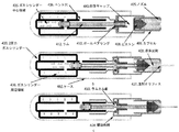
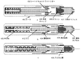
図4は、ボールベアリングトリガー432および2圧力ガスシリンダー420を有する、装置の異なる態様を示す。図4ではボールベアリングトリガー432および2圧力ガスシリンダー420が一緒に示されたが、これらは独立しており、前記および下記の態様と個々に組み合わせることができることを理解すべきである。他の構成要素、例えば、ピストン408、薬物カプセル406、ノズル405、注射オリフィス427、液体製剤428、キャップ(図示せず)、およびケース402の機能は、前記のように図1に示した類似の構成要素に似ている。 FIG. 4 shows a different embodiment of the apparatus having a ball bearing trigger 432 and a two pressure gas cylinder 420. Although ball bearing trigger 432 and two pressure gas cylinder 420 are shown together in FIG. 4, it should be understood that they are independent and can be combined individually with the embodiments described above and below. The functions of other components such as piston 408, drug capsule 406, nozzle 405, injection orifice 427, liquid formulation 428, cap (not shown), and case 402 are similar to those shown in FIG. Similar to component.
図4に示したボールベアリングトリガー態様では、ラム412の中にはカム面433が機械加工されている。図4に示したように、カム面433は、ラム412を右側に駆り立てる加圧ガスの力によってボールベアリング432を半径方向に、外向きに駆り立てる。図4aに示したように、カプセル406に取り付けられた摺動部材434がボールベアリング432、従って、ラム412を捕捉し、そのため、ラム412は右側に動かない。送達のために装置を調製した後に、好ましくは、前記のように調製した後に、ノズル405を望ましい注射部位に押しつける。これによって、図4bに示したように、ボールベアリング432が、もはやその半径方向の動きを拘束しない摺動部材434の部分に到達するまで、摺動部材434はボールベアリング432に対して動く。ラム412にあるカム面433が及ぼす力によって、ボールベアリング432は半径方向に動き、ラム412を解放する。前記の態様のように、ラム412は衝撃ギャップ443の端から端まで飛行し、ピストン408にぶつかって、穿刺段階に関連する圧力スパイクを作り出す。次いで、図4cに示したように、ガス圧力に駆り立てられて、ラム412およびピストン408は左側に動かされて、送達段階を作り出す。図4にも示したように、この態様は、送達事象が完了した後に加圧ガスを出すことができる任意のベント穴436を有する。 In the ball bearing trigger embodiment shown in FIG. 4, a cam surface 433 is machined in the ram 412. As shown in FIG. 4, the cam surface 433 drives the ball bearing 432 radially and outward by the force of the pressurized gas that drives the ram 412 to the right. As shown in FIG. 4a, a sliding member 434 attached to the capsule 406 captures the ball bearing 432 and thus the ram 412 so that the ram 412 does not move to the right. After preparing the device for delivery, and preferably as described above, the nozzle 405 is pressed against the desired injection site. This causes the sliding member 434 to move relative to the ball bearing 432 until the ball bearing 432 reaches a portion of the sliding member 434 that no longer constrains its radial movement, as shown in FIG. The force exerted by the cam surface 433 on the ram 412 causes the ball bearing 432 to move radially and release the ram 412. As in the previous embodiment, the ram 412 flies across the impact gap 443 and hits the piston 408 to create a pressure spike associated with the puncture phase. Then, as shown in FIG. 4c, driven by gas pressure, the ram 412 and piston 408 are moved to the left to create a delivery phase. As also shown in FIG. 4, this embodiment has an optional vent hole 436 through which pressurized gas can be vented after the delivery event is complete.
図4はまたガスシリンダーの2圧力態様も示す。この態様において、ラム412は保存中に第1の力に供され、起動されると、ガスシリンダー中心領域437の中の圧力により衝撃ギャップ443の端から端まで飛行する。この後、送達段階の間に、ラム412は、中心領域437からのガスとガスシリンダー周辺領域438からのガスの組み合わされた効果である第2の、好ましくはさらに弱い力に供される。さらに、この態様は、穿刺段階および送達段階の特性の独立した最適化を可能にする。関連する態様において(図示せず)、ガスシリンダー435の中心部分438は、ガスばねではなく機械式ばね、例えば、コイルばねまたは皿ばねスタックを備える。この態様は、ラム412がピストン408にぶつかる前に、ばねがゼロ点を通過するのであれば、その後に、ラム412が、ガスシリンダー435の周辺領域438の中にあるガスの圧力でしか前方に駆り立てられないので、第1の力および第2の力の完全独立性を可能にする。 FIG. 4 also shows a two pressure embodiment of the gas cylinder. In this embodiment, the ram 412 is subjected to a first force during storage and, when activated, flies across the impact gap 443 due to pressure in the gas cylinder central region 437. After this, during the delivery phase, the ram 412 is subjected to a second, preferably even weaker force, which is the combined effect of gas from the central region 437 and gas from the gas cylinder peripheral region 438. Furthermore, this aspect allows for independent optimization of the characteristics of the puncture stage and the delivery stage. In a related embodiment (not shown), the central portion 438 of the gas cylinder 435 comprises a mechanical spring, such as a coil spring or a disc spring stack, rather than a gas spring. This aspect is that if the spring passes through the zero point before the ram 412 hits the piston 408, then the ram 412 will only move forward with the pressure of the gas in the peripheral region 438 of the gas cylinder 435. Because it is not driven, it allows complete independence of the first and second forces.
図5は、カプセル/ラムシリンダー506の中でラムシリンダー、ラムガイド、およびガラスカプセルの機能が組み合わされ、トリガーが、プッシュボタン540によって破壊される壊れやすいガスシリンダーシール539を備える本発明の態様を示す。図5において、このトリガー態様およびラムガイド/薬物容器態様が一緒に示されたが、これらは独立しており、前記および下記の態様と個々に組み合わせることができることを理解すべきである。他の構成要素、例えば、ガスシリンダー520、ピストン508、ノズル505、注射オリフィス527、液体製剤528、キャップ(図示せず)、およびケース502の機能は、前記のように図1に示した類似の構成要素に似ている。 FIG. 5 illustrates an embodiment of the invention in which the functions of a ram cylinder, ram guide, and glass capsule are combined in a capsule / ram cylinder 506 and the trigger comprises a fragile gas cylinder seal 539 that is broken by a push button 540. Show. In FIG. 5, this trigger embodiment and ram guide / drug container embodiment are shown together, but it should be understood that they are independent and can be combined individually with the embodiments described above and below. The functions of other components such as gas cylinder 520, piston 508, nozzle 505, injection orifice 527, liquid formulation 528, cap (not shown), and case 502 are similar to those shown in FIG. Similar to component.
図5に示した態様において、カプセル/ラムシリンダー506のガラス管は引き伸ばされ、ラム512は、ガラス管と接触している一対のラムシール526によって誘導および密閉される。ラム512は、金属またはポリマーを含む任意の材料から作ることができる。ラムシール526は、Oリング、シーリンググリース、またはオーバーモールドポリマーを含む多くのやり方で作ることができる。1つの態様において、ラムおよびシールは一片のPTFEから機械加工される。別の態様において、ラム512は、ラムシール526がオーバーモールドされた機械加工された真鍮であるか、またはラムシール526はOリングシールである。保存時、および送達のための取扱いおよび調製の間に、図5aに示したように、ラム512の位置は、ラム512の左側に、破裂可能なダイヤフラム541によって画定される空気間隙、右側にラム512およびピストン508によって画定される空気間隙によって維持される。ラム512が動くのであれば、空気圧差が発生して、ラム512をその平衡位置に戻す傾向がある復元力が作り出される。図5bに示したように、装置が起動された時、ガスシリンダー520からの空気圧は、破裂可能なダイヤフラム541を破裂させ、その後、ガスがラム512に圧力を加える。その後に、図5cに示したように、ガス圧力の力によってラム512は右側に駆り立てられる。ここで、ラム512はピストン508にぶつかって、穿刺段階を作り出し、次いで、送達段階中に加圧ガスの力によって液体製剤528を送達する。 In the embodiment shown in FIG. 5, the glass tube of the capsule / ram cylinder 506 is stretched and the ram 512 is guided and sealed by a pair of ram seals 526 in contact with the glass tube. The ram 512 can be made from any material including metal or polymer. The ram seal 526 can be made in many ways including an O-ring, sealing grease, or overmolded polymer. In one embodiment, the ram and seal are machined from a single piece of PTFE. In another embodiment, the ram 512 is machined brass with a ram seal 526 overmolded, or the ram seal 526 is an O-ring seal. During storage and during handling and preparation for delivery, as shown in Figure 5a, the location of the ram 512 is on the left side of the ram 512, the air gap defined by the rupturable diaphragm 541, the ram on the right side. Maintained by an air gap defined by 512 and piston 508. If the ram 512 moves, an air pressure difference will be created, creating a restoring force that tends to return the ram 512 to its equilibrium position. As shown in FIG. 5b, when the apparatus is activated, the air pressure from the gas cylinder 520 ruptures the rupturable diaphragm 541, after which the gas applies pressure to the ram 512. Thereafter, the ram 512 is driven to the right by the force of the gas pressure, as shown in FIG. 5c. Here, the ram 512 hits the piston 508 to create a puncture phase and then delivers the liquid formulation 528 by the force of pressurized gas during the delivery phase.
ガスシリンダー530が、壊れやすいシール539で密閉されたトリガーの態様も図5に示した。図5aは、オリフィスキャップが取り外された、送達可能状態にある装置を示す。この態様において、使用者は装置を望ましい注射部位に押しつけ、次いで、プッシュボタン540をトリガーに押しつける。図5bに示したように、プッシュボタン540を押しつけると、壊れやすいガスシリンダーシール539が破壊されて、ガスが逃げ、装置が起動する。 An embodiment of a trigger in which the gas cylinder 530 is sealed with a fragile seal 539 is also shown in FIG. FIG. 5a shows the device ready for delivery with the orifice cap removed. In this embodiment, the user presses the device against the desired injection site and then presses the push button 540 against the trigger. As shown in FIG. 5b, when the push button 540 is pressed, the fragile gas cylinder seal 539 is broken, the gas escapes and the device is activated.
図6は、動力源が、圧縮された皿ばねスタック620であり、トリガーの別の態様ではシートメダルストラト(sheet medal strut)トリガー632である本発明の態様を示す。図6において、このトリガーおよび動力源は一緒に示されたが、これらは独立しており、前記および下記の態様と個々に組み合わせることができることを理解すべきである。他の構成要素、例えば、ピストン608、注射オリフィス627、液体製剤628、薬物カプセル606、キャップ(図示せず)、およびケース602の機能は、前記のように図1に示した類似の構成要素に似ている。 FIG. 6 shows an embodiment of the invention in which the power source is a compressed disc spring stack 620 and in another embodiment of the trigger is a sheet medal strut trigger 632. In FIG. 6, this trigger and power source are shown together, but it should be understood that they are independent and can be combined individually with the embodiments described above and below. The functions of other components such as piston 608, injection orifice 627, liquid formulation 628, drug capsule 606, cap (not shown), and case 602 are similar to the similar components shown in FIG. It is similar.
図6に示した態様では、注射のための力が、圧縮された皿ばねスタック620によって供給される。動力源のこの態様には、漏出が起こらず、気密シールが不要という事実を含めて、ある特定の利点がある。システムの機能は、図1に示した、および前記の機能に似ている。図6aは、キャップが取り外された、送達可能状態にあるシステムを示す。6bに示したように、装置が起動された時に、皿ばねスタック620によってラム612は衝撃ギャップ643の端から端まで飛行し、ピストン608にぶつかって、穿刺段階の圧力スパイクが作り出される。その後に、皿ばねスタック620はラム612を介してピストン608を動かし、送達段階の間に液体製剤628を送達する。異なるばね定数の皿ばねスタックを使用すると、送達パラメータをいくらか調整することができる。図6bに示したように、個々の皿ばねを2つ以上の入れ子状ワッシャーと交換することによって、さらに高い率の皿ばねスタックを構築することができる。皿ばねの一部または全てを入れ子状ワッシャーと交換することによって、正確に調整されたばね力を実現することができる。 In the embodiment shown in FIG. 6, the force for injection is supplied by a compressed disc spring stack 620. This aspect of the power source has certain advantages, including the fact that no leakage occurs and no hermetic seal is required. The function of the system is similar to that shown in FIG. 1 and described above. FIG. 6a shows the system ready for delivery with the cap removed. As shown in 6b, when the device is activated, the belleville spring stack 620 causes the ram 612 to fly across the impact gap 643 and hit the piston 608, creating a puncture pressure spike. Thereafter, the Belleville spring stack 620 moves the piston 608 through the ram 612 to deliver the liquid formulation 628 during the delivery phase. Using different spring constant disc spring stacks allows some adjustment of the delivery parameters. As shown in FIG. 6b, a higher rate Belleville spring stack can be constructed by exchanging individual Belleville springs with two or more nested washers. By exchanging part or all of the disc spring with a nested washer, a precisely adjusted spring force can be realized.
トリガーであるシートメタルストラトトリガー632の別の態様も図6に示した。この態様は、前記のボールベアリングトリガーにいくらか似ているが、ボールベアリング432は、図6に示したシートメタルストラトトリガー632と交換されている。図6aにおいて、装置は起動可能状態で示された。ラム612の上にあるカム面633はシートメタルストラト632を外向きに駆り立てるが、その動きは、薬物カプセル606に機械的に取り付けられた摺動部材634によってブロックされる。装置が望ましい注射部位に押しつけられた時に、図6bに示したように摺動部材634は左側に動いて、ストラト632を所定の位置に保持している摺動部材634の拘束が取り外され、これによって、次に、ストラト632はカム面633の力によって半径方向に、外向きに動くことが可能になり、ラム612が解放され、装置が起動する。前記の態様と同様に、ラム612は衝撃ギャップ643の端から端まで飛行し、ピストン608にぶつかって、穿刺段階に関連した圧力スパイクが作り出される。 Another embodiment of the sheet metal strat trigger 632 as a trigger is also shown in FIG. This embodiment is somewhat similar to the ball bearing trigger described above, but the ball bearing 432 has been replaced with a sheet metal strat trigger 632 shown in FIG. In FIG. 6a, the device is shown in a startable state. The cam surface 633 above the ram 612 drives the sheet metal strat 632 outward, but its movement is blocked by a sliding member 634 mechanically attached to the drug capsule 606. When the device is pressed against the desired injection site, the sliding member 634 moves to the left, as shown in FIG. 6b, removing the restraint of the sliding member 634 holding the strut 632 in place. In turn allows the strat 632 to move radially outward by the force of the cam surface 633, releasing the ram 612 and activating the device. Similar to the previous embodiment, the ram 612 flies across the impact gap 643 and hits the piston 608 to create a pressure spike associated with the puncture phase.
図7は、装置のさらなる態様を示す。この態様では、図4に示した、および前記の態様にいくらか関連しており、動力源は、中心機械式ばね735(図示した)またはガスばね(図示せず)を有する二部ガスシリンダー720である。他の構成要素、例えば、ラム712、ピストン708、カプセル706、ノズル705、注射オリフィス727、液体製剤728、キャップ(図示せず)、およびケース702の機能は、前記のように図1に示した機能と似ている。ここでは、図7aに示したように、中心ばね735は巻き付けられ、駆動トリガーボタン740を有する装置の左側においてトリガーアセンブリ744に取り付けられた中心ロッド742によって捕捉される。誤った起動を阻止するために、トリガーボタン740は、装置を送達可能状態にするために送達直前に回転される。次いで、図7bに示したように、ノズル705は望ましい送達部位に押しつけられ、トリガーボタン740は、中心ロッド742を解放するために押しつけられ、次いで、中心ロッド742はラム712を右側に衝撃ギャップ743の端から端まで動かす。送達の残りは前記の通りである。前記の図4の説明のように、中心領域735およびガスシリンダー720の周辺領域738のばね力は、送達圧力プロファイルの特性を調整するように独立して調節することができる。1つの好ましい態様では、図7bに示したように、中心ばね735による力は、ラム712を右側に動かして、ガスシリンダー720の周辺領域738の圧力に曝露するのにまさに十分な力である。この時に、周辺領域738の圧力は、穿刺段階および送達段階のためのエネルギーを供給する。これによって、送達前のラム712およびトリガーアセンブリ740に対する力は最小限になる。これによって、トリガー信頼性の改善、および必要とされる駆動力の最小化が可能になり、保存中の装置構成要素のクリープおよび変形が最小限になる。 FIG. 7 shows a further embodiment of the device. In this embodiment, and somewhat related to the previous embodiment shown in FIG. 4, the power source is a two-part gas cylinder 720 having a central mechanical spring 735 (shown) or a gas spring (not shown). is there. The functions of other components such as ram 712, piston 708, capsule 706, nozzle 705, injection orifice 727, liquid formulation 728, cap (not shown), and case 702 are shown in FIG. 1 as described above. Similar to function. Here, as shown in FIG. 7a, the central spring 735 is wrapped and captured by a central rod 742 attached to the trigger assembly 744 on the left side of the device with the drive trigger button 740. To prevent false activation, the trigger button 740 is rotated just prior to delivery to bring the device into a deliverable state. Then, as shown in FIG. 7b, the nozzle 705 is pressed against the desired delivery site, the trigger button 740 is pressed to release the center rod 742, and the center rod 742 then pushes the ram 712 to the right with an impact gap 743. Move from end to end. The rest of the delivery is as described above. As described above with respect to FIG. 4, the spring force of the central region 735 and the peripheral region 738 of the gas cylinder 720 can be independently adjusted to adjust the characteristics of the delivery pressure profile. In one preferred embodiment, as shown in FIG. 7b, the force by the center spring 735 is just enough to move the ram 712 to the right to expose the pressure in the peripheral region 738 of the gas cylinder 720. At this time, the pressure in the peripheral region 738 provides energy for the puncture and delivery phases. This minimizes the force on the ram 712 and trigger assembly 740 prior to delivery. This allows for improved trigger reliability and minimization of the required driving force, minimizing creep and deformation of the device components during storage.
図8は、ラム812がトリガーアセンブリ844によって解放されて、ガスバイパス845が露出し、加圧ガスがバイパス845を通って流入する時に、ガス圧力がピストンに直接作用する以外は、図7に示した、および前記の態様と概念上、非常に似た態様を示す。 FIG. 8 is shown in FIG. 7 except that gas pressure acts directly on the piston when the ram 812 is released by the trigger assembly 844 to expose the gas bypass 845 and pressurized gas flows through the bypass 845. In addition, an embodiment very similar in concept to the above embodiment is shown.
図9は、ラム912が、衝撃およびガス放出のための統合されたタイミングを有する回転スラップハンマーラムである、本発明の態様を示す。この態様はスプールバルブ921トリガー態様を用いて示されたが、他の態様、例えば、壊れやすいガスシールバルブ539を用いて使用できることを理解すべきである。他の構成要素、例えば、ピストン908、薬物カプセル906、注射オリフィス927、キャップ(図示せず)、ガスシリンダー920、液体製剤928、およびケース902の機能は、前記のように図1に示した機能と似ている。図9aは、オリフィスキャップが取り外され、全ての安全機構が発射可能形態にある、発射可能形態にある装置を示す。図9bに示したように、装置が起動された時に、ねじりばね946によって駆り立てられた回転スラップハンマーラム912は反時計回りに回転して、衝撃力を伝える構成要素947にぶつかる。衝撃力を伝える構成要素947はラム912の衝撃力をピストン908に伝えて、穿刺段階のために製剤の圧力スパイクが作り出される。同時に、ラム912はバルブアクチュエータ948にぶつかる。バルブアクチュエータ948は圧力バルブ921を駆動し、ガスシリンダー920から加圧ガスを放出し、図9cに示したようにピストン908を下向きに動かし、送達段階において液体製剤928を送達する。この態様は、衝撃部材912の機能を送達力と完全に切り離すという利点を有し、ガスシールに必要な条件を衝撃部材912から取り除いている。 FIG. 9 illustrates an embodiment of the present invention where the ram 912 is a rotating slap hammer ram with integrated timing for impact and gas release. While this embodiment has been shown with the spool valve 921 trigger embodiment, it should be understood that other embodiments can be used, such as the fragile gas seal valve 539. The functions of other components such as piston 908, drug capsule 906, injection orifice 927, cap (not shown), gas cylinder 920, liquid formulation 928, and case 902 are the functions shown in FIG. 1 as described above. Is similar. FIG. 9a shows the device in a fireable configuration with the orifice cap removed and all safety features in the fireable configuration. As shown in FIG. 9b, when the device is activated, the rotating slap hammer ram 912 driven by the torsion spring 946 rotates counterclockwise and hits a component 947 that transmits the impact force. The impact force transmitting component 947 transmits the impact force of the ram 912 to the piston 908 to create a pressure spike of the formulation for the puncture stage. At the same time, ram 912 hits valve actuator 948. The valve actuator 948 drives the pressure valve 921, releases the pressurized gas from the gas cylinder 920, moves the piston 908 downward as shown in FIG. 9c, and delivers the liquid formulation 928 in the delivery phase. This embodiment has the advantage of completely decoupling the function of the impact member 912 from the delivery force and removes the requirements for gas sealing from the impact member 912.
図10は、中空ラム1012および後方に取り付けられたトリガーアセンブリ1044を有する、本発明のさらなる態様を示す。他の構成要素、例えば、ピストン1008、薬物カプセル1006、キャップ(図示せず)、注射オリフィス1027、ガスシリンダー1020、衝撃ギャップ1043、液体製剤1028、ラムシリンダー1013、およびケース1002の機能は、前記のように図1に示した機能と似ている。この態様において、ガスシリンダー1020は、ラムシリンダー1013の外側にある環状領域と中空ラム1012の内部領域である。図10aに示したように、中空ラム1012は加圧ガスによって右側に駆り立てられるが、ラムタブ1049によって捕捉される。図10aは、オリフィスキャップが取り外された発射可能形態にある装置、および発射可能状態にある任意の安全機構(例えば、トリガーボタン1040の回転。図7および前記の説明を参照されたい)を示す。図10bに示したように、注射オリフィス1027は望ましい送達部位に押しつけられ、トリガーボタン1040は押される。トリガーボタン1040が押しつけられると、中空ラム1012はラムタブ1049から離脱する。図10に示した態様では、これは、ラムタブ1049がもはやラムシリンダー1013と係合しないように、中空ラム1012の端を変形することによってなされるが、他の態様が可能であり、例えば、ラムシリンダー1013の端は外向きに変形される。中空ラム1012がラムタブ1049から切り離された時、図10cに示したように右側に自由に移動して、ピストン1008にぶつかって穿刺段階のための圧力スパイクを作り出す。次いで、加圧ガスは、カプセル1006を通してラム1012およびピストン1008を動かし続け、送達段階において製剤1028を送達する。図10は、中空ラム1012の外側にあるラムシール1026を示すが、ラムシリンダー1013の内側にも配置することができる。 FIG. 10 shows a further embodiment of the present invention having a hollow ram 1012 and a trigger assembly 1044 attached to the rear. The functions of other components, such as piston 1008, drug capsule 1006, cap (not shown), injection orifice 1027, gas cylinder 1020, impact gap 1043, liquid formulation 1028, ram cylinder 1013, and case 1002, are described above. Is similar to the function shown in FIG. In this embodiment, the gas cylinder 1020 is an annular region outside the ram cylinder 1013 and an inner region of the hollow ram 1012. As shown in FIG. 10a, the hollow ram 1012 is driven to the right by pressurized gas but is captured by the ram tab 1049. FIG. 10a shows the device in a fireable configuration with the orifice cap removed, and any safety mechanism in a fireable state (eg, rotation of the trigger button 1040; see FIG. 7 and the above description). As shown in FIG. 10b, the injection orifice 1027 is pressed against the desired delivery site and the trigger button 1040 is pressed. When the trigger button 1040 is pressed, the hollow ram 1012 disengages from the ram tab 1049. In the embodiment shown in FIG. 10, this is done by deforming the end of the hollow ram 1012 so that the ram tab 1049 no longer engages the ram cylinder 1013, although other embodiments are possible, such as a ram The end of the cylinder 1013 is deformed outward. When the hollow ram 1012 is disconnected from the ram tab 1049, it moves freely to the right as shown in FIG. 10c and hits the piston 1008 to create a pressure spike for the puncture stage. The pressurized gas then continues to move the ram 1012 and piston 1008 through the capsule 1006 to deliver the formulation 1028 in the delivery phase. FIG. 10 shows the ram seal 1026 on the outside of the hollow ram 1012, but can also be placed inside the ram cylinder 1013.
下記実施例は、本発明をどのように製造し、使用するかについての完全な開示および説明を当業者に提供するために出されたものであり、本発明者らが発明と考える範囲を制限するものではなく、下記実験が実施した全てまたは唯一の実験であることを示すものでもない。使用した数値(例えば、量、温度など)については正確さを確保するために努力したが、いくらかの実験誤差および偏差を計上すべきである。特に記載がなければ、部は重量部であり、分子量は重量平均分子量であり、温度は℃であり、圧力は大気圧または約大気圧である。 The following examples are given to provide those skilled in the art with a complete disclosure and explanation of how to make and use the present invention and limit the scope of what the inventors regard as the invention. It is not intended to indicate that the experiment below is all or the only experiment performed. Efforts have been made to ensure accuracy with respect to numbers used (eg amounts, temperature, etc.) but some experimental errors and deviations should be accounted for. Unless indicated otherwise, parts are parts by weight, molecular weight is weight average molecular weight, temperature is in degrees Centigrade, and pressure is at or near atmospheric.
実施例1
実施例1では、図1に示した、および前記のシステムの重要なエナージャイザー特徴を有する実験プロトタイプに対して試験を行った。プロトタイプの外観図を図11aに示した。装置を皮膚に押しつけることによって起動の効果を模倣するために、スプール1117を解放するための単純なカラー1150を設ける。製剤カプセル1106はスチールから製作され、1mLの液体製剤1128を閉じ込め、直径0.41mmの注射オリフィス1127を備えた。ガスシリンダー1120を、ガス供給源接続1151を介して60バールまで加圧した。ラム1112をシヤーピン1152によって所定の位置に保持した。プロトタイプの操作を図11cに示した。カラー1150は上に摺動し、スプール1117を解放し、スプール1117は図11cに見られるように左側に移動する。これによって、加圧ガスはガスシリンダー1120から流入してガス入口1123を通り、スプール1117によって空になった領域を通り、ガス出口1122から出る。これによって、加圧ガスはラムヘッド1114を介してラム1112に力を加える。この力は、シヤーピン1152を破壊して、ラムを解放してピストン1108にぶつけ、その後に、液体製剤1128を動かして注射オリフィス1127に通すのに十分な力であった。液体製剤1128の圧力プロファイル対時間を図12aに示した。これは、0.5mLの製剤体積を有する‘086に記載のタイプのシステムのシステムの類似データを表す図12bと比較することができる。図12aに示したように、穿刺段階の圧力スパイクは望ましい圧力スパイクより低い(図12bを参照されたい)。しかしながら、穿刺段階の圧力スパイクは、衝撃ギャップを増やすことによって高めることができる。送達段階中の圧力は‘086システムに匹敵し、製剤体積が2倍であるので予想と一致して、送達時間は約2倍である。
Example 1
Example 1 was tested on an experimental prototype shown in FIG. 1 and having the important energizer features of the system described above. An external view of the prototype is shown in FIG. 11a. A simple collar 1150 is provided to release the spool 1117 to mimic the effect of activation by pressing the device against the skin. Formulation capsule 1106 was made from steel and contained 1 mL of liquid formulation 1128 and was equipped with a 0.41 mm diameter injection orifice 1127. The gas cylinder 1120 was pressurized to 60 bar via a gas supply connection 1151. The ram 1112 was held in place by the shear pin 1152. The operation of the prototype is shown in Figure 11c. The collar 1150 slides up and releases the spool 1117, which moves to the left as seen in FIG. 11c. As a result, the pressurized gas flows in from the gas cylinder 1120, passes through the gas inlet 1123, passes through the area emptied by the spool 1117, and exits from the gas outlet 1122. Thereby, the pressurized gas applies a force to the ram 1112 via the ram head 1114. This force was sufficient to break the shear pin 1152, release the ram and hit the piston 1108, and then move the liquid formulation 1128 through the injection orifice 1127. The pressure profile versus time for liquid formulation 1128 is shown in FIG. 12a. This can be compared to FIG. 12b, which represents similar data for a system of the type of system described in '086 having a 0.5 mL formulation volume. As shown in FIG. 12a, the pressure spike at the puncture stage is lower than the desired pressure spike (see FIG. 12b). However, the pressure spike at the puncture stage can be increased by increasing the impact gap. The pressure during the delivery phase is comparable to the '086 system, and the delivery time is approximately double, as expected, since the formulation volume is double.
実施例2
実施例2では、実施例1に記載のように実験用器具を用いて試験を行ったが、‘086装置において用いられたものと同一の0.5mLガラス製剤カプセルを使用した。この試験の結果を図13に示した。この試験の結果は、実施例1において見られる穿刺段階圧力の同じ低下があったが、‘086装置からの結果(図12b)に極めて匹敵することが分かる。
Example 2
In Example 2, the test was performed using laboratory equipment as described in Example 1, but the same 0.5 mL glass formulation capsules used in the '086 apparatus were used. The results of this test are shown in FIG. The results of this test are found to be very comparable to the results from the '086 device (FIG. 12b), with the same reduction in puncture stage pressure seen in Example 1.
実施例3
実施例3では、図4に示した、および前記のデュアルガスシリンダーを模倣するように設計された実験用プロトタイプ(外観図については図14aを参照されたい)に対して試験を行った。2圧力は、ガスシリンダー中心領域1435に第1の圧力P1を充填し、次いで、ガスシリンダー周辺領域1438に第2のさらに低い圧力P2を充填することによって達成された。ラッチ1453を用いて、ラム1414(明確に示すために、ラムシールは省かれていることに注意のこと)は所定の位置に保持した。製剤カプセル1406はスチールから製作され、体積1mLの液体製剤1428を閉じ込め、直径0.4mmの注射オリフィス1427を備えた。ガスシリンダー中心領域1435には、200MPaの圧力P1まで充填した。ガスシリンダー周辺領域1438には180MPaの圧力P2まで充填した。図14cに示したように、ラッチ1453が右側に押された時に、ラム1414は放出され、ガスシリンダー中心領域1435の加圧ガスの力によって衝撃ギャップ1443の端から端まで加速され、その後に、ピストン1408にぶつかって、穿刺段階の圧力スパイクが作り出される。次いで、図14dに示したように、ラム1414およびピストン1408は、ガスシリンダー中心領域1435およびガスシリンダー周辺領域1438のガスの組み合わされた圧力の力によって下向きに駆り立てられ続け、液体製剤1428を注射オリフィス1427に通して、送達段階が作り出される。図15は、製剤圧力対時間の測定の結果を示し、0.5mLの薬物製剤体積を有する‘086に記載のタイプの装置を用いてなされた類似の測定の結果を表す図12bと比較することができる。図14に見られるように、2圧力ガスシリンダーを有するシステムは、‘086システムとほぼ同一の穿刺段階圧力を実現し、従って、同様の皮下注射結果を実現するはずである。予想されたように薬物製剤体積が2倍であるため、送達段階の持続期間は‘086システムと比較してデュアル圧力システムの約2倍であった。しかしながら、2圧力システムの送達段階中の圧力はほぼ一定であり、これとは対照に、‘086システムは送達段階中の圧力の著しい減少を示した。図12bを1mL送達に外挿すると、送達の終わりには圧力がほぼゼロになることが示唆されるであろう。
Example 3
In Example 3, tests were performed on the experimental prototype shown in FIG. 4 and designed to mimic the dual gas cylinder described above (see FIG. 14a for exterior view). Two pressures were achieved by filling the gas cylinder central region 1435 with the first pressure P1, and then filling the gas cylinder peripheral region 1438 with the second, lower pressure P2. A latch 1453 was used to hold the ram 1414 (note that the ram seal has been omitted for clarity) in place. Formulation capsule 1406 was made of steel and contained a 1 mL volume of liquid formulation 1428 and was equipped with a 0.4 mm diameter injection orifice 1427. The gas cylinder center region 1435 was filled up to a pressure P1 of 200 MPa. The gas cylinder peripheral area 1438 was filled up to a pressure P2 of 180 MPa. As shown in FIG.14c, when the latch 1453 is pushed to the right, the ram 1414 is released and accelerated from end to end of the impact gap 1443 by the force of the pressurized gas in the gas cylinder central region 1435, after which The piston 1408 strikes and creates a puncture stage pressure spike. 14d, the ram 1414 and piston 1408 then continue to be driven downward by the combined pressure force of the gas in the gas cylinder central region 1435 and gas cylinder peripheral region 1438 to draw the liquid formulation 1428 into the injection orifice Through 1427, a delivery phase is created. FIG. 15 shows the results of the measurement of formulation pressure versus time and can be compared with FIG. it can. As seen in FIG. 14, a system with a two pressure gas cylinder should achieve approximately the same puncture stage pressure as the '086 system, and therefore should achieve similar subcutaneous injection results. As expected, the drug formulation volume was twice, so the duration of the delivery phase was about twice that of the dual pressure system compared to the '086 system. However, the pressure during the delivery phase of the two pressure system is nearly constant, in contrast, the '086 system showed a significant decrease in pressure during the delivery phase. Extrapolating FIG. 12b to 1 mL delivery will suggest that the pressure is near zero at the end of delivery.
本発明は、最も現実的かつ好ましい態様だと考えられる形で本明細書において示され、説明された。しかしながら、本発明の範囲内で逸脱がなされてもよく、本開示を読むと、当業者にとって明らかな変更が加えられることが認められる。 The present invention has been shown and described herein in what is considered to be the most realistic and preferred embodiment. However, departures may be made within the scope of the present invention, and it will be appreciated that modifications will be apparent to those skilled in the art upon reading this disclosure.
本発明について本発明の特定の態様を参照して記載してきたが、当業者であれば、本発明の真の精神および範囲から逸脱せずに、様々な変更が可能であること、等価物を代わりに用いてもよいことを理解すべきである。さらに、特別な状況、材料、組成物、プロセス、1つまたは複数のプロセス段階を本発明の目的、精神、および範囲に適合させるように多くの改変を実施してもよい。そのような改変は全て、添付の特許請求の範囲内にあるものとする。 Although the invention has been described with reference to specific embodiments of the invention, those skilled in the art will recognize that various modifications and equivalents can be made without departing from the true spirit and scope of the invention. It should be understood that it may be used instead. In addition, many modifications may be made to adapt a particular situation, material, composition of matter, process, process step or steps, to the objective, spirit and scope of the present invention. All such modifications are intended to be within the scope of the appended claims.
Claims (50)
保存中にガスシリンダーを加圧状態に維持する保存シールを備えるスプール;
加圧ガスをチャンバーに放出する形でスプールを解放するための手段;
放出された加圧ガスによって前方に駆り立てられるような形でチャンバー内に摺動可能に配置されたラム;および
薬物送達オリフィスと流体連通した液体薬物製剤を保持する薬物容器
を備え、放出された加圧ガスによってラムは強制的に動かされて、液体製剤は薬物送達オリフィスを通って送達される、無針注射器。 Pressurized gas cylinder;
A spool with a storage seal that keeps the gas cylinder under pressure during storage;
Means for releasing the spool in a manner that releases pressurized gas into the chamber;
A ram slidably disposed within the chamber in a manner such that it can be driven forward by the released pressurized gas; and a drug container holding a liquid drug formulation in fluid communication with the drug delivery orifice, A needleless syringe in which the ram is forced by the pressurized gas and the liquid formulation is delivered through the drug delivery orifice.
ピストン構成要素が液体薬物製剤と接触し、
ピストン構成要素が薬物容器の中の液体薬物を密閉する、
請求項7記載の無針注射器。 Before releasing the spool, the ram is separated from the piston component by the air gap by the air gap,
The piston component contacts the liquid drug formulation;
The piston component seals the liquid drug in the drug container;
The needleless syringe according to claim 7.
まわして取る;
折り取る;
カチッと鳴らして取る;および
引っ張って取る
より選択される動作によって取り外される、請求項10記載の無針注射器。 The cap is
Rotate around;
Tear off;
11. The needleless syringe of claim 10, wherein the needleless syringe is removed by an action selected from clicking and pulling; and pulling and pulling.
剪断すること;
変形させること;
ラムと保持要素との間の摩擦に打ち勝つこと;
アクチュエータにより駆動されること;および
それらの組み合わせ
より選択される機構によってラムを解放する、請求項21記載の無針注射器。 The holding element is
Shearing;
Deforming;
Overcoming the friction between the ram and the holding element;
24. The needleless syringe of claim 21, wherein the ram is released by a mechanism selected from an actuator; and combinations thereof.
該ノズル構成要素が、保存中に製剤の漏出が起こらないほど十分に強固にガラス構成要素に保持され;
さらに、注射器が起動された時に、該ノズル構成要素が、製剤の漏出が起こらないほど十分に強固にガラス構成要素に保持される、
請求項5記載の無針注射器。 The drug delivery container comprises a nozzle component with a drug delivery orifice and a separate borosilicate glass component, the borosilicate glass being a circular tube;
The nozzle component is held in the glass component sufficiently firmly that no leakage of the formulation occurs during storage;
Further, when the syringe is activated, the nozzle component is held in the glass component sufficiently firmly so that no leakage of the formulation occurs.
6. The needleless syringe according to claim 5.
薬物容器の一部である;
薬物容器に取り付けられている;
薬物容器に対して一定の距離で強固に保持された無針注射器の構成要素に取り付けられている
より選択される特性を特徴とする、請求項31記載の無針注射器。 A first set of threads engages a corresponding set of threads, and the corresponding set of threads is
Part of a drug container;
Attached to drug containers;
32. Needleless syringe according to claim 31, characterized in that it is more selected than being attached to a component of a needleless syringe that is firmly held at a certain distance to the drug container.
液体薬物製剤に通じている、容器中のオリフィス;
第1の圧力で第1の加圧ガスを含有する第1のガスリザーバ;
薬物投与部材と接触し、薬物投与部材を前方に駆り立てる第1の加圧ガスであって、薬物投与部材の動きがトリガー機構によって妨げられる、第1の加圧ガス;
第2の圧力で第2の加圧ガスを含有する第2のガスリザーバ
を備え、
該投与部材は該トリガー機構によって解放されるまで、該第2の加圧ガスによって前方に駆り立てられない、無針注射器。 Drug capsules containing liquid drug formulations;
An orifice in a container leading to a liquid drug formulation;
A first gas reservoir containing a first pressurized gas at a first pressure;
A first pressurized gas that contacts the drug delivery member and drives the drug delivery member forward, wherein the first pressurized gas is prevented from moving by the trigger mechanism;
Comprising a second gas reservoir containing a second pressurized gas at a second pressure;
A needleless syringe that is not driven forward by the second pressurized gas until the dosing member is released by the trigger mechanism.
投与部材がピストン構成要素と接触し、該ピストン構成要素が液体薬物製剤と接触する、請求項38記載の無針注射器。 The drug delivery member is not in contact with the liquid drug formulation,
39. The needleless syringe of claim 38, wherein the dosing member contacts a piston component, and the piston component contacts a liquid drug formulation.
皮下注射;および
筋肉内注射
より選択される注射を生じるように、第1の圧力、第2の圧力、ガス流路を露出するために投与部材が移動しなければならない距離、投与部材とピストン構成要素との間の距離、および少なくとも1つのオリフィスの面積が選択される、請求項38記載の無針注射器。 Intradermal injection;
The first pressure, the second pressure, the distance that the dosing member must travel to expose the gas flow path, the dosing member and the piston configuration to produce an injection selected from subcutaneous injection; and intramuscular injection 39. A needleless syringe according to claim 38, wherein the distance between the elements and the area of at least one orifice is selected.
オリフィス;
エネルギー源;
ボールベアリングを備えるトリガー機構
を備え、該トリガー機構が無針注射器を起動し、該エネルギー源が該液体薬物の大半を、少なくとも1つの該オリフィスを通るように押し出す、無針注射器。 Drug capsules containing liquid drugs;
Orifice;
Energy source;
A needleless syringe comprising a trigger mechanism comprising a ball bearing, wherein the trigger mechanism activates a needleless syringe and the energy source pushes a majority of the liquid drug through the at least one orifice.
機械式コイルばね;
皿ばねスタック(Belleville washer stack);および
圧縮ガスばね
より選択される、請求項44記載の無針注射器。 Spring is
Mechanical coil spring;
45. A needleless syringe according to claim 44, selected from a Belleville washer stack; and a compressed gas spring.
Applications Claiming Priority (3)
| Application Number | Priority Date | Filing Date | Title |
|---|---|---|---|
| US201161431325P | 2011-01-10 | 2011-01-10 | |
| US61/431,325 | 2011-01-10 | ||
| PCT/US2012/020654 WO2012096889A1 (en) | 2011-01-10 | 2012-01-09 | Improved needle free injectors |
Related Child Applications (1)
| Application Number | Title | Priority Date | Filing Date |
|---|---|---|---|
| JP2016171384A Division JP2016221342A (en) | 2011-01-10 | 2016-09-02 | Improved needleless injector |
Publications (2)
| Publication Number | Publication Date |
|---|---|
| JP2014508565A true JP2014508565A (en) | 2014-04-10 |
| JP2014508565A5 JP2014508565A5 (en) | 2014-11-27 |
Family
ID=46507396
Family Applications (2)
| Application Number | Title | Priority Date | Filing Date |
|---|---|---|---|
| JP2013548606A Pending JP2014508565A (en) | 2011-01-10 | 2012-01-09 | Improved needleless syringe |
| JP2016171384A Pending JP2016221342A (en) | 2011-01-10 | 2016-09-02 | Improved needleless injector |
Family Applications After (1)
| Application Number | Title | Priority Date | Filing Date |
|---|---|---|---|
| JP2016171384A Pending JP2016221342A (en) | 2011-01-10 | 2016-09-02 | Improved needleless injector |
Country Status (9)
| Country | Link |
|---|---|
| US (1) | US20160199579A1 (en) |
| EP (1) | EP2663350A4 (en) |
| JP (2) | JP2014508565A (en) |
| CN (1) | CN103370092B (en) |
| AU (1) | AU2012205735B8 (en) |
| BR (1) | BR112013017561A2 (en) |
| CA (1) | CA2822908A1 (en) |
| RU (1) | RU2587011C2 (en) |
| WO (1) | WO2012096889A1 (en) |
Cited By (3)
| Publication number | Priority date | Publication date | Assignee | Title |
|---|---|---|---|---|
| JP2016538983A (en) * | 2013-11-01 | 2016-12-15 | コンソート・メディカル・パブリック・リミテッド・カンパニー | Drug delivery device subassembly |
| JP2017521195A (en) * | 2014-07-25 | 2017-08-03 | ベーリンガー インゲルハイム インターナショナル ゲゼルシャフト ミット ベシュレンクテル ハフツング | Drug delivery device |
| JP7425657B2 (en) | 2020-03-30 | 2024-01-31 | テルモ株式会社 | drug administration equipment |
Families Citing this family (35)
| Publication number | Priority date | Publication date | Assignee | Title |
|---|---|---|---|---|
| CN103230633B (en) * | 2013-04-12 | 2014-12-10 | 肖长正 | Continuous needleless injector pressurized by reducing cylinder |
| DE112014003721T5 (en) | 2013-08-12 | 2016-04-28 | Tk Holdings, Inc. | Pressurized actuator |
| CN105556130B (en) * | 2013-08-12 | 2017-07-21 | Tk控股公司 | Pressurized actuator |
| ITMI20132067A1 (en) | 2013-12-11 | 2015-06-12 | Dante Lorini | EQUIPMENT FOR THE TRANSDERMIC INOCULATION OF MEDICINATIONS |
| CN103977481A (en) * | 2014-05-14 | 2014-08-13 | 苏州大学张家港工业技术研究院 | Pneumatic energy storage needleless syringe |
| WO2015172686A1 (en) * | 2014-05-14 | 2015-11-19 | 苏州大学张家港工业技术研究院 | Pneumatic accumulating needleless syringe |
| CA2977060C (en) | 2015-02-20 | 2023-09-05 | Regeneron Pharmaceuticals, Inc. | Syringe systems, piston seal systems, stopper systems, and methods of use and assembly |
| CN105498044A (en) * | 2016-01-13 | 2016-04-20 | 北京步腾医学科技有限公司 | Disposable pneumatic needleless injector and using method thereof |
| CN105498046A (en) * | 2016-01-13 | 2016-04-20 | 北京步腾医学科技有限公司 | Pneumatic needleless injector |
| CN105852883B (en) * | 2016-04-12 | 2018-10-30 | 李懿莎 | A kind of negative pressure sucking disc type blood sample automatic collector |
| CN105903010A (en) * | 2016-05-11 | 2016-08-31 | 内蒙古华希生物科技有限公司 | Needleless injection foot-and-mouth disease vaccine system and application |
| CN105854010A (en) * | 2016-05-11 | 2016-08-17 | 长春海基亚生物技术股份有限公司 | Hand-foot-mouth disease vaccine system for needleless injection and application |
| CN105999253A (en) * | 2016-05-11 | 2016-10-12 | 内蒙古华希生物科技有限公司 | Brucellosis vaccine needle-free injection system and application |
| CN105833393A (en) * | 2016-05-11 | 2016-08-10 | 内蒙古华希生物科技有限公司 | Needle-free injection rabies virus vaccine system and application |
| CN105999258A (en) * | 2016-05-11 | 2016-10-12 | 内蒙古华希生物科技有限公司 | Pig virus vaccine needle-free injection system and application |
| GB2556632A (en) * | 2016-11-18 | 2018-06-06 | Owen Mumford Ltd | Medicament delivery device |
| CN107252512B (en) * | 2017-06-16 | 2018-03-13 | 南阳市中心医院 | A kind of gas-driven needle-less syringe |
| EP3609681A4 (en) * | 2017-07-27 | 2020-12-02 | Hewlett-Packard Development Company, L.P. | Lid of a build material carriage of a three-dimensional (3d) printer |
| US10695497B2 (en) | 2017-08-01 | 2020-06-30 | International Business Machines Corporation | Subcutaneous jet injector with a manually operated injector pump |
| CN108042886B (en) * | 2017-12-27 | 2021-05-11 | 四川护理职业学院 | Simple needleless injector |
| KR101859735B1 (en) * | 2018-02-07 | 2018-05-21 | 주식회사 피테크 | Painless injection device |
| KR102107578B1 (en) * | 2018-05-02 | 2020-05-07 | 주식회사 피테크 | Constant velocity infusion device for painless syringe and painless sylinge having the same |
| KR102104080B1 (en) * | 2018-05-02 | 2020-04-23 | 주식회사 피테크 | Sonic vibration device for painless syringe and painless sylinge having the same |
| KR101907552B1 (en) | 2018-05-03 | 2018-10-12 | 주식회사 피테크 | Painless injection device without needle |
| CN108784884B (en) * | 2018-06-19 | 2020-12-15 | 刘晓东 | Needleless injector for livestock raising |
| US11472131B2 (en) * | 2018-08-06 | 2022-10-18 | Portal Instruments, Inc. | Injection nozzle and method of making same |
| US11484898B2 (en) * | 2018-08-23 | 2022-11-01 | Gofire, Inc. | System and method for vaporizing cartridge system with diffuser |
| KR102199724B1 (en) * | 2018-10-05 | 2021-01-07 | 주식회사 피테크 | Painless injection device without needle |
| KR102362940B1 (en) * | 2020-04-21 | 2022-02-14 | 김기남 | Injection device for liquid |
| KR102427261B1 (en) * | 2020-06-15 | 2022-08-02 | 유수옥 | Injector |
| TWI806182B (en) * | 2020-11-18 | 2023-06-21 | 潔霺生醫科技股份有限公司 | Multi-stage gas actuated medicine supply device and method |
| CN113398384B (en) * | 2021-06-24 | 2022-02-08 | 江苏铂可医疗科技有限公司 | High-pressure locking prevention structure and method for needleless injector |
| CN113582391B (en) * | 2021-08-02 | 2023-08-08 | 湖南省九牛环保科技有限公司 | Efficient sewage treatment purifying tank and purifying method |
| WO2023173142A2 (en) * | 2022-03-11 | 2023-09-14 | Aktivax, Inc. | Dispensing device incorporating a diaphragm |
| WO2024010102A1 (en) * | 2022-07-04 | 2024-01-11 | 김기남 | Liquid material injection device |
Citations (3)
| Publication number | Priority date | Publication date | Assignee | Title |
|---|---|---|---|---|
| US20020123717A1 (en) * | 2001-03-05 | 2002-09-05 | Bioject Medical Technologies Inc. | Disposable needle-free injection apparatus and method |
| JP2004526519A (en) * | 2001-04-13 | 2004-09-02 | ペンジェット・コーポレーション | Modular gas pressure needleless syringe |
| JP2005052669A (en) * | 1993-07-31 | 2005-03-03 | Weston Medical Ltd | Needle-less injector |
Family Cites Families (13)
| Publication number | Priority date | Publication date | Assignee | Title |
|---|---|---|---|---|
| US5599302A (en) * | 1995-01-09 | 1997-02-04 | Medi-Ject Corporation | Medical injection system and method, gas spring thereof and launching device using gas spring |
| US5730723A (en) * | 1995-10-10 | 1998-03-24 | Visionary Medical Products Corporation, Inc. | Gas pressured needle-less injection device and method |
| GB9607549D0 (en) * | 1996-04-11 | 1996-06-12 | Weston Medical Ltd | Spring-powered dispensing device |
| GB9818110D0 (en) * | 1998-08-19 | 1998-10-14 | Weston Medical Ltd | Needleless injectors and other devices |
| US6981660B2 (en) * | 2000-09-25 | 2006-01-03 | Evit Labs | Shock wave aerosolization apparatus and method |
| US6645170B2 (en) * | 2001-03-05 | 2003-11-11 | Bioject Medical Technologies, Inc. | Simplified disposable needle-free injection apparatus and method |
| US20050192530A1 (en) * | 2001-04-13 | 2005-09-01 | Penjet Corporation | Method and apparatus for needle-less injection with a degassed fluid |
| US6648850B2 (en) * | 2001-06-08 | 2003-11-18 | Bioject, Inc. | Durable needle-less jet injector apparatus and method |
| EP1441787B2 (en) * | 2001-11-09 | 2014-02-26 | ALZA Corporation | Pneumatic powered autoinjector |
| WO2003088893A2 (en) * | 2002-04-19 | 2003-10-30 | Equidyne Systems, Inc. | Multi-component ampule |
| HU225252B1 (en) * | 2003-08-21 | 2006-08-28 | S Istvan Lindmayer | Needleless injection apparatus |
| US7776007B2 (en) * | 2003-12-05 | 2010-08-17 | Zogenix, Inc. | Device for readying a needle free injector for delivery |
| US7618393B2 (en) * | 2005-05-03 | 2009-11-17 | Pharmajet, Inc. | Needle-less injector and method of fluid delivery |
-
2012
- 2012-01-09 CN CN201280004860.1A patent/CN103370092B/en not_active Expired - Fee Related
- 2012-01-09 WO PCT/US2012/020654 patent/WO2012096889A1/en active Application Filing
- 2012-01-09 CA CA2822908A patent/CA2822908A1/en not_active Abandoned
- 2012-01-09 JP JP2013548606A patent/JP2014508565A/en active Pending
- 2012-01-09 BR BR112013017561A patent/BR112013017561A2/en not_active IP Right Cessation
- 2012-01-09 US US13/823,003 patent/US20160199579A1/en not_active Abandoned
- 2012-01-09 AU AU2012205735A patent/AU2012205735B8/en not_active Ceased
- 2012-01-09 RU RU2013137457/14A patent/RU2587011C2/en not_active IP Right Cessation
- 2012-01-09 EP EP12734647.6A patent/EP2663350A4/en not_active Withdrawn
-
2016
- 2016-09-02 JP JP2016171384A patent/JP2016221342A/en active Pending
Patent Citations (3)
| Publication number | Priority date | Publication date | Assignee | Title |
|---|---|---|---|---|
| JP2005052669A (en) * | 1993-07-31 | 2005-03-03 | Weston Medical Ltd | Needle-less injector |
| US20020123717A1 (en) * | 2001-03-05 | 2002-09-05 | Bioject Medical Technologies Inc. | Disposable needle-free injection apparatus and method |
| JP2004526519A (en) * | 2001-04-13 | 2004-09-02 | ペンジェット・コーポレーション | Modular gas pressure needleless syringe |
Cited By (3)
| Publication number | Priority date | Publication date | Assignee | Title |
|---|---|---|---|---|
| JP2016538983A (en) * | 2013-11-01 | 2016-12-15 | コンソート・メディカル・パブリック・リミテッド・カンパニー | Drug delivery device subassembly |
| JP2017521195A (en) * | 2014-07-25 | 2017-08-03 | ベーリンガー インゲルハイム インターナショナル ゲゼルシャフト ミット ベシュレンクテル ハフツング | Drug delivery device |
| JP7425657B2 (en) | 2020-03-30 | 2024-01-31 | テルモ株式会社 | drug administration equipment |
Also Published As
| Publication number | Publication date |
|---|---|
| WO2012096889A1 (en) | 2012-07-19 |
| CN103370092B (en) | 2016-09-28 |
| BR112013017561A2 (en) | 2016-10-11 |
| RU2587011C2 (en) | 2016-06-10 |
| AU2012205735A1 (en) | 2013-05-02 |
| AU2012205735B2 (en) | 2014-08-14 |
| CN103370092A (en) | 2013-10-23 |
| JP2016221342A (en) | 2016-12-28 |
| AU2012205735B8 (en) | 2014-09-18 |
| CA2822908A1 (en) | 2012-07-19 |
| US20160199579A1 (en) | 2016-07-14 |
| EP2663350A1 (en) | 2013-11-20 |
| RU2013137457A (en) | 2015-02-20 |
| EP2663350A4 (en) | 2018-01-24 |
Similar Documents
| Publication | Publication Date | Title |
|---|---|---|
| JP2016221342A (en) | Improved needleless injector | |
| US9662449B2 (en) | Needle-free injectors and design parameters thereof that optimize injection performance | |
| RU2179864C2 (en) | Needleless injector | |
| JP4660190B2 (en) | Drug delivery system | |
| AU2001283333A1 (en) | Modified disposable injector device | |
| JP2010509030A (en) | Needleless syringe and fluid delivery method | |
| IL151465A (en) | Miniaturized needleless injector | |
| US20170065771A1 (en) | Piston closures for drug delivery capsules | |
| US6602222B1 (en) | Disposable injection device | |
| US20210308380A1 (en) | Injector | |
| AU2013203986B2 (en) | Improved Needle Free Injectors | |
| WO2016137665A1 (en) | Needle-free injectors comprising sound suppression |
Legal Events
| Date | Code | Title | Description |
|---|---|---|---|
| A521 | Written amendment |
Free format text: JAPANESE INTERMEDIATE CODE: A523 Effective date: 20140515 |
|
| A521 | Written amendment |
Free format text: JAPANESE INTERMEDIATE CODE: A523 Effective date: 20141007 |
|
| A621 | Written request for application examination |
Free format text: JAPANESE INTERMEDIATE CODE: A621 Effective date: 20141007 |
|
| RD04 | Notification of resignation of power of attorney |
Free format text: JAPANESE INTERMEDIATE CODE: A7424 Effective date: 20150318 |
|
| A977 | Report on retrieval |
Free format text: JAPANESE INTERMEDIATE CODE: A971007 Effective date: 20150911 |
|
| A131 | Notification of reasons for refusal |
Free format text: JAPANESE INTERMEDIATE CODE: A131 Effective date: 20151014 |
|
| A521 | Written amendment |
Free format text: JAPANESE INTERMEDIATE CODE: A523 Effective date: 20151214 |
|
| A02 | Decision of refusal |
Free format text: JAPANESE INTERMEDIATE CODE: A02 Effective date: 20160512 |
|
| A521 | Written amendment |
Free format text: JAPANESE INTERMEDIATE CODE: A821 Effective date: 20160902 |
|
| A601 | Written request for extension of time |
Free format text: JAPANESE INTERMEDIATE CODE: A601 Effective date: 20171101 |