JP2014504545A - Masking strip - Google Patents
Masking strip Download PDFInfo
- Publication number
- JP2014504545A JP2014504545A JP2013546412A JP2013546412A JP2014504545A JP 2014504545 A JP2014504545 A JP 2014504545A JP 2013546412 A JP2013546412 A JP 2013546412A JP 2013546412 A JP2013546412 A JP 2013546412A JP 2014504545 A JP2014504545 A JP 2014504545A
- Authority
- JP
- Japan
- Prior art keywords
- backing
- masking strip
- gap
- strip according
- masking
- Prior art date
- Legal status (The legal status is an assumption and is not a legal conclusion. Google has not performed a legal analysis and makes no representation as to the accuracy of the status listed.)
- Pending
Links
Images
Classifications
-
- C—CHEMISTRY; METALLURGY
- C09—DYES; PAINTS; POLISHES; NATURAL RESINS; ADHESIVES; COMPOSITIONS NOT OTHERWISE PROVIDED FOR; APPLICATIONS OF MATERIALS NOT OTHERWISE PROVIDED FOR
- C09J—ADHESIVES; NON-MECHANICAL ASPECTS OF ADHESIVE PROCESSES IN GENERAL; ADHESIVE PROCESSES NOT PROVIDED FOR ELSEWHERE; USE OF MATERIALS AS ADHESIVES
- C09J7/00—Adhesives in the form of films or foils
- C09J7/20—Adhesives in the form of films or foils characterised by their carriers
- C09J7/22—Plastics; Metallised plastics
-
- B—PERFORMING OPERATIONS; TRANSPORTING
- B05—SPRAYING OR ATOMISING IN GENERAL; APPLYING FLUENT MATERIALS TO SURFACES, IN GENERAL
- B05C—APPARATUS FOR APPLYING FLUENT MATERIALS TO SURFACES, IN GENERAL
- B05C21/00—Accessories or implements for use in connection with applying liquids or other fluent materials to surfaces, not provided for in groups B05C1/00 - B05C19/00
- B05C21/005—Masking devices
-
- C—CHEMISTRY; METALLURGY
- C09—DYES; PAINTS; POLISHES; NATURAL RESINS; ADHESIVES; COMPOSITIONS NOT OTHERWISE PROVIDED FOR; APPLICATIONS OF MATERIALS NOT OTHERWISE PROVIDED FOR
- C09J—ADHESIVES; NON-MECHANICAL ASPECTS OF ADHESIVE PROCESSES IN GENERAL; ADHESIVE PROCESSES NOT PROVIDED FOR ELSEWHERE; USE OF MATERIALS AS ADHESIVES
- C09J7/00—Adhesives in the form of films or foils
- C09J7/20—Adhesives in the form of films or foils characterised by their carriers
- C09J7/22—Plastics; Metallised plastics
- C09J7/26—Porous or cellular plastics
-
- B—PERFORMING OPERATIONS; TRANSPORTING
- B05—SPRAYING OR ATOMISING IN GENERAL; APPLYING FLUENT MATERIALS TO SURFACES, IN GENERAL
- B05B—SPRAYING APPARATUS; ATOMISING APPARATUS; NOZZLES
- B05B12/00—Arrangements for controlling delivery; Arrangements for controlling the spray area
- B05B12/16—Arrangements for controlling delivery; Arrangements for controlling the spray area for controlling the spray area
- B05B12/20—Masking elements, i.e. elements defining uncoated areas on an object to be coated
- B05B12/24—Masking elements, i.e. elements defining uncoated areas on an object to be coated made at least partly of flexible material, e.g. sheets of paper or fabric
-
- B—PERFORMING OPERATIONS; TRANSPORTING
- B05—SPRAYING OR ATOMISING IN GENERAL; APPLYING FLUENT MATERIALS TO SURFACES, IN GENERAL
- B05B—SPRAYING APPARATUS; ATOMISING APPARATUS; NOZZLES
- B05B12/00—Arrangements for controlling delivery; Arrangements for controlling the spray area
- B05B12/16—Arrangements for controlling delivery; Arrangements for controlling the spray area for controlling the spray area
- B05B12/20—Masking elements, i.e. elements defining uncoated areas on an object to be coated
- B05B12/26—Masking elements, i.e. elements defining uncoated areas on an object to be coated for masking cavities
- B05B12/265—Masking elements, i.e. elements defining uncoated areas on an object to be coated for masking cavities between a door and a post, e.g. foam strips
-
- B—PERFORMING OPERATIONS; TRANSPORTING
- B05—SPRAYING OR ATOMISING IN GENERAL; APPLYING FLUENT MATERIALS TO SURFACES, IN GENERAL
- B05D—PROCESSES FOR APPLYING FLUENT MATERIALS TO SURFACES, IN GENERAL
- B05D7/00—Processes, other than flocking, specially adapted for applying liquids or other fluent materials to particular surfaces or for applying particular liquids or other fluent materials
- B05D7/14—Processes, other than flocking, specially adapted for applying liquids or other fluent materials to particular surfaces or for applying particular liquids or other fluent materials to metal, e.g. car bodies
-
- C—CHEMISTRY; METALLURGY
- C09—DYES; PAINTS; POLISHES; NATURAL RESINS; ADHESIVES; COMPOSITIONS NOT OTHERWISE PROVIDED FOR; APPLICATIONS OF MATERIALS NOT OTHERWISE PROVIDED FOR
- C09J—ADHESIVES; NON-MECHANICAL ASPECTS OF ADHESIVE PROCESSES IN GENERAL; ADHESIVE PROCESSES NOT PROVIDED FOR ELSEWHERE; USE OF MATERIALS AS ADHESIVES
- C09J7/00—Adhesives in the form of films or foils
- C09J7/20—Adhesives in the form of films or foils characterised by their carriers
- C09J7/22—Plastics; Metallised plastics
- C09J7/24—Plastics; Metallised plastics based on macromolecular compounds obtained by reactions involving only carbon-to-carbon unsaturated bonds
- C09J7/241—Polyolefin, e.g.rubber
- C09J7/243—Ethylene or propylene polymers
-
- C—CHEMISTRY; METALLURGY
- C09—DYES; PAINTS; POLISHES; NATURAL RESINS; ADHESIVES; COMPOSITIONS NOT OTHERWISE PROVIDED FOR; APPLICATIONS OF MATERIALS NOT OTHERWISE PROVIDED FOR
- C09J—ADHESIVES; NON-MECHANICAL ASPECTS OF ADHESIVE PROCESSES IN GENERAL; ADHESIVE PROCESSES NOT PROVIDED FOR ELSEWHERE; USE OF MATERIALS AS ADHESIVES
- C09J2203/00—Applications of adhesives in processes or use of adhesives in the form of films or foils
- C09J2203/31—Applications of adhesives in processes or use of adhesives in the form of films or foils as a masking tape for painting
-
- C—CHEMISTRY; METALLURGY
- C09—DYES; PAINTS; POLISHES; NATURAL RESINS; ADHESIVES; COMPOSITIONS NOT OTHERWISE PROVIDED FOR; APPLICATIONS OF MATERIALS NOT OTHERWISE PROVIDED FOR
- C09J—ADHESIVES; NON-MECHANICAL ASPECTS OF ADHESIVE PROCESSES IN GENERAL; ADHESIVE PROCESSES NOT PROVIDED FOR ELSEWHERE; USE OF MATERIALS AS ADHESIVES
- C09J2301/00—Additional features of adhesives in the form of films or foils
- C09J2301/20—Additional features of adhesives in the form of films or foils characterized by the structural features of the adhesive itself
- C09J2301/204—Additional features of adhesives in the form of films or foils characterized by the structural features of the adhesive itself the adhesive coating being discontinuous
Landscapes
- Chemical & Material Sciences (AREA)
- Organic Chemistry (AREA)
- Life Sciences & Earth Sciences (AREA)
- Engineering & Computer Science (AREA)
- Wood Science & Technology (AREA)
- Chemical Kinetics & Catalysis (AREA)
- Details Or Accessories Of Spraying Plant Or Apparatus (AREA)
- Coating Apparatus (AREA)
Abstract
塗装する2つの基材の間の間隙の内側面を遮蔽するためのマスキングストリップが提供される。このストリップは、第1の面及び第2の面を有する裏材であって、第1の面がマスキングストリップを間隙の内側面に固定する接着剤領域を有する裏材と、裏材から延在し、間隙に塗料が流れ込まないように構成された間隙充填材と、を含み、裏材の第1の面には、ストリップが固定される間隙の内側面からマスキングストリップの裏材を離隔するように構成された間隔設定手段も設けられており、マスキングストリップは予備形成される。 A masking strip is provided for shielding the inner surface of the gap between the two substrates to be painted. The strip is a backing having a first surface and a second surface, the first surface having an adhesive region that secures the masking strip to the inner surface of the gap, and extending from the backing. And a gap filler configured to prevent the paint from flowing into the gap, the first side of the backing separating the masking strip backing from the inner surface of the gap to which the strip is secured. An interval setting means is also provided, and the masking strip is preformed.
Description
本明細書で開示する発明は、塗装する2つの基材間の間隙の内側を遮蔽するためのマスキングストリップに関し、より具体的には、自動車又は他の大型車体の吹き付け塗装中に用いるためのマスキングストリップに関する。 The invention disclosed herein relates to a masking strip for shielding the interior of a gap between two substrates to be painted, and more specifically, masking for use during spray painting of an automobile or other large vehicle body. Regarding strips.
車体の外側は、互いに対して移動する部品、例えば、固定されたドアポスト及び可動式のドアフレームを有する。固定部品と可動部品との間には、通常、湾曲した、目に見える間隙が存在する。間隙の幅及び深さは、自動車のモデル、並びに固定部品及び可動部品の相対位置によって様々である。同様に、間隙は、2つの固定部品の間、又は2つの可動部品の間に形成されて存在し得るか、単一部品内で形成され得る。自動車に吹き付け塗装を施すと、2つの部品又は基材によって形成された間隙に塗料が流れ込む。この過剰な吹き付けは望ましくなく、修正を要する。 The outside of the vehicle body has components that move relative to each other, such as a fixed door post and a movable door frame. There is usually a curved, visible gap between the stationary part and the moving part. The width and depth of the gap varies depending on the vehicle model and the relative positions of the stationary and moving parts. Similarly, a gap can exist formed between two fixed parts, or between two movable parts, or can be formed within a single part. When spray coating is applied to an automobile, the paint flows into a gap formed by two parts or substrates. This excessive spraying is undesirable and requires correction.
かかる間隙への塗料の流れ込みを克服するために、様々な方法及び装置が開発され、採用されてきた。1つの方法は、自動車の固定部品又は可動部品の内側面に発泡体状材料のストリップを付着させることである。この材料は、間隙への塗料の更なる流れ込みを防止するが、発泡体状材料と固定部品又は可動部品との間に塗料が堆積するため、この材料を除去すると、触感的にも視覚的にも明らかな、望ましくない起伏のある塗装縁部が生じる。 Various methods and devices have been developed and employed to overcome the flow of paint into such gaps. One method is to deposit a strip of foam-like material on the inside surface of the stationary or moving part of the automobile. This material prevents the paint from flowing further into the gap, but the paint accumulates between the foam-like material and the stationary or moving parts, so removing this material will allow tactile and visual inspection. Obviously, undesirable undulating paint edges are produced.
採用される別の技法は、マスキングテープストリップの一部を縦方向に折り畳み、テープの非粘着部分が外側に突出するように自動車の固定部品の内側面にマスキングテープの粘着部分を貼付してから、可動部品を閉止して自動車の吹き付け塗装を行う前に発泡系材料のストリップをマスキングテープに貼付することである。折り畳んだテープの非粘着部分は、マスキングテープが固定部品に吹き付けられた塗料に接触しないようにする。この技法は、より滑らか塗装ラインをもたらすことが多いが、特定形状の間隙のみに好適である。一部の自動車では、発泡体系材料は、間隙内から外側に突出する程度まで可動部品によって圧縮される。この結果、塗料が可動部品の表面と発泡体との間を「埋める」ようになる。したがって、発泡体及びテープを除去すると、かかる塗料の堆積は起伏のある塗装縁部をもたらす。更に、この技法には時間がかかり、かつテープ及び発泡体を正しく位置付けるための相当の熟練を要する。 Another technique employed is to fold a portion of the masking tape strip in the vertical direction and apply the masking tape adhesive part to the inside surface of the fixed part of the car so that the non-adhesive part of the tape protrudes outward. It is to apply a strip of foamed material to the masking tape before closing the moving parts and spraying the car. The non-adhesive part of the folded tape prevents the masking tape from coming into contact with the paint sprayed on the stationary part. This technique often results in a smoother paint line, but is only suitable for certain shaped gaps. In some automobiles, the foam-based material is compressed by moving parts to the extent that it projects outwardly from within the gap. As a result, the paint “fills” between the surface of the movable part and the foam. Thus, when the foam and tape are removed, such paint build-up results in a rough paint edge. Furthermore, this technique is time consuming and requires considerable skill to correctly position the tape and foam.
折り畳んだマスキングテープを用いることの更なる欠点は、間隙が湾曲しているためにテープが自動車部品から持ち上がる傾向にあり、塗料が過剰に堆積することが多いことである。 A further disadvantage of using a folded masking tape is that the tape tends to lift from the automotive part due to the curved gaps, and the paint often accumulates excessively.
したがって、滑らかな塗装ラインを実現しつつ、様々な間隙形状の間隙に塗料が流れ込まないようにすることが望ましい。 Therefore, it is desirable to prevent the paint from flowing into gaps having various gap shapes while realizing a smooth coating line.
したがって、塗装する2つの基材の間の間隙の内側面を遮蔽するためのマスキングストリップが提供される。このストリップは、第1の面及び第2の面を有する裏材であって、第1の面がマスキングストリップを間隙の内側面に固定する接着剤領域を有する裏材と、裏材から延在し、間隙に塗料が流れ込まないように構成された間隙充填材と、を含み、裏材の第1の面には、ストリップが固定される間隙の内側面からマスキングストリップの裏材を離隔するように構成された間隔設定手段も設けられており、マスキングストリップは予備形成される。 Accordingly, a masking strip is provided for shielding the inner surface of the gap between the two substrates to be painted. The strip is a backing having a first surface and a second surface, the first surface having an adhesive region that secures the masking strip to the inner surface of the gap, and extending from the backing. And a gap filler configured to prevent the paint from flowing into the gap, the first side of the backing separating the masking strip backing from the inner surface of the gap to which the strip is secured. An interval setting means is also provided, and the masking strip is preformed.
添付の特許請求の範囲及び本発明の下記の実施形態の説明に、本発明の好ましい、特に有用な特徴を記載する。 Preferred and particularly useful features of the invention are set forth in the appended claims and in the following description of embodiments of the invention.
本発明の好ましい実施形態の発明を実施するための形態を以下に示す。 The form for implementing invention of preferable embodiment of this invention is shown below.
以下の説明における「塗装」とは、ベースコート(自動車で見られる着色塗装層)及びクリアコート(ラッカーの別名でも知られる)を含むことを理解されたい。また、滑らかな塗装縁部とは、感触が滑らかであり、塗装コーティングの縁部に指の爪が引っかからない縁部である。 It should be understood that “painting” in the following description includes base coats (colored paint layers found in automobiles) and clear coats (also known as lacquers). In addition, a smooth painted edge is an edge that has a smooth feel and does not catch a fingernail on the edge of the paint coating.
図1は、塗装する2つの基材の間の間隙の概略図である。両基材は、塗装する自動車部品で形成される。間隙1は、固定部品2と可動部品3との間に形成される。図示の例では、固定部品2は「B」ピラーであり、可動部品3はドアである。しかし、この概念は、他の固定自動車部品及び可動自動車部品にも拡大して適用される。固定部品2は、塗装する第1の基材4を示し、可動部品3は、塗装する第2の基材5を示す。間隙1は、2つの内側面を含む。第1の内側面6は固定部品2の内側面で形成され、第2の内側面7は可動部品3の内側面で形成される。間隙1の最上部8は、塗装する第1の基材4及び第2の基材5と一致するものとして画定される。可動部品3の内側面は、可動部品3の外殻を形成する材料の厚さによって事実上決定される転換点Tを有する曲面を含む。塗装ラインPLmは、第2の基材5の塗装領域と可動部品3の非塗装領域との間の境界において可動部品3上に形成され、これより上では部品の表面が塗料に曝され、これよりも下では表面が塗料に曝されないラインである。塗装ラインPLmは、通常、転換点Tに隣接して位置するか、転換点Tに位置する。塗装ラインPLsは、マスキングストリップの位置決めに応じて間隙1の最上部8に近接して固定部品2の上に形成される。塗料の滑らかな塗布を実現するためには、塗装ラインPLm及びPLsにおける塗布が重要である。したがって、理想的には、塗装ラインPLm及びPLsにおいて、マスキングストリップと、間隙1の内側面6、7の部分と、任意のマスキングストリップ構成要素との接触は最小限、又は全く接触してはならない。しかし塗装ラインの位置は、したがって、自動車の種類、型、及びモデル、及び間隙の形状、並びに以下で詳述するマスキングストリップの総合的な位置決めに応じて異なる。
FIG. 1 is a schematic view of the gap between two substrates to be painted. Both base materials are formed of automobile parts to be painted. The
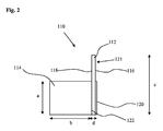
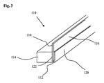
図2及び図3を参照すると、マスキングストリップ110は、裏材112と、間隙充填材114と、を含む。間隙充填材114は可撓性、圧縮性、及び/又は形状適合性材料の区域であり、発泡体状材料、好ましくはポリウレタン発泡体などの独立気泡発泡体材料、より好ましくはCaligen X4200AM(登録商標)であってよい。全ての実施形態において、間隙充填材(114、214、314)の材料は、全ての寸法において間隙の湾曲にぴったり一致できることが好ましい。間隙充填材114の高さ「a」は約5mmであり、好ましくは3mm〜7mmである。幅「b」は約10mmであり、好ましくは5mm〜15mmである。当然のことながら、幾つかの実施形態では、高さ「a」は長さbよりも大きくてよい。
2 and 3, the
裏材112は可撓性、圧縮性、及び/又は形状適合性材料のストリップであり、好ましくは発泡体材料であり、より好ましくはポリエチレン発泡体材料であり、より好ましくはAveolite TA1001(登録商標)である。全ての実施形態において、裏材(112、212、312)の材料は、マスキングストリップ110が表面から持ち上がることなく、全ての寸法において間隙の湾曲及び裏材を貼付する内側面の湾曲にぴったり一致できることが好ましい。裏材112の材料は、好ましくは間隙充填材114の材料よりも高密度である。裏材112は、第1の面116と、第1の面116と反対側の第2の面118と、を有する。端部正面図(図2)で見ると、裏材112の高さ「c」は約8mmであり、好ましくは5mm〜11mmである。裏材112の幅、つまり厚さ「d」は約1mmであり、好ましくは0.8mm〜1.2mmである。
The
裏材112の第1の面116は接着剤領域120を有する。裏材112の接着剤領域120は、マスキングストリップが表面から離れにくいものの、使用後に車体部分からマスキングストリップを除去するときに接着剤が残留しないように、使用中に間隙の内側面にマスキングストリップを固定できる任意の好適な接着剤を含む。1つの形態では、接着剤は、3M Laminating Adhesive 300LSEで積層した3M 3434マスキングテープである。第1の面116の高さ「c」に沿った接着剤領域120の高さは約5mmであり、好ましくは3mm〜7mmである。
The
また、裏材112の第1の面116は、高さが約3mmであり、好ましくは2mm〜4mmである無接着剤領域121を有する。使用時には、無接着剤領域121は、裏材の最上部が、マスキングストリップを貼付する間隙の内側面に付着しないようにする。無接着剤領域121は、下記で詳述するように、裏材112の無接着剤領域121に近位の塗装する基材又は車体部分で滑らかな塗装ラインを実現するためにストリップを貼付する表面から裏材を離隔する手段として作用する。
Also, the
裏材112及び間隙充填材114は任意の好適な手段によって境界面122で互いに固定されるが、好ましくは、裏材112及び間隙充填材114が互いに接着され、通常の使用では分離しにくいように、接着剤によって貼り付けられる。当然のことながら、接着剤領域120は、裏材112の第2の面118で境界面122領域が占めるのとほぼ同じ面積の裏材112の第1の面116を占める。マスキングストリップ110の非使用時には、接着剤領域120は、取り外し可能な保護テープによって保護されてよい。図3に示すように、マスキングストリップ110は、一体型の細長いストリップであり、それに応じて、間隙内で貼付されるように構成される。
The
図4及び5は、改善されたマスキングストリップ110を示す。これらの図において、同様の特徴は同一の参照番号によって示される。同様に、間隙充填材114、裏材112、及び裏材112の接着剤領域120は、好ましくは図2及び3を参照して上述した対応する構成要素と同一の材料及び寸法である。図4及び5を参照すると、マスキングストリップ110は、裏材112の第1の面116の前述の「無接着剤」領域121から延在するスペーサ124を更に含む。スペーサ124は、好ましくは裏材112の第1の面116の領域121の全領域を占めて、新たな無接着剤領域121aをもたらす。この形態では、スペーサ124は、下記で詳述するように、使用中に、スペーサ124に近位の塗装する基材で滑らかな塗装ラインを実現するために、マスキングストリップ110を貼付する面から裏材112を離隔する手段として作用する。
4 and 5 show an
スペーサ124は、可撓性の形状適合性材料であり、好ましくは、ポリエチレン発泡体などの発泡体材料、より好ましくはAveolite TA1008(商標)である。スペーサ124は、裏材112と同一の材料であってよい。断面図で見ると、スペーサ124の幅は約0.8mmであり、好ましくは0.6mm〜1.1mmである。スペーサ124の高さは約3mmであり、好ましくは3mm〜8mmの高さである。裏材112及びスペーサ124は、好ましくは間隙充填材114の材料よりも高密度の材料である。
The
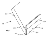
図6及び7は、本発明の第2の実施形態を示す。図2、3、4、及び5で示す同様の構成要素は、先頭に数字の2を付けた同一の下2桁で示す。間隙充填材214は可撓性、圧縮性、及び形状適合性材料のストリップであり、好ましくは発泡体材料、より好ましくはポリウレタン発泡体などの独立気泡発泡体材料、より好ましくはCaligen x4200AM(商標)である。断面図で見ると、間隙充填材214の縁部215の長さ「b」は約15mmであり、好ましくは10mm〜22mmである。幅「a」は約4mmであるが、好ましくは3mm〜8mmである。裏材212の高さcは約8mmであるが、好ましくは5mm〜11mmである。裏材212の幅は、約1mmであり、好ましくは0.8mm〜1.2mmである。裏材212の高さcは上述と同様に約8mmであり、スペーサ224の高さは上述と同様に約3mmである。
6 and 7 show a second embodiment of the present invention. Similar components shown in FIGS. 2, 3, 4, and 5 are indicated by the same last two digits prefixed with the
間隙充填材214は、境界面222の接着剤領域226によって裏材212の第2の面218に固定される。接着剤領域226は、裏材212及び間隙充填材214が互いに接着され、通常の使用では分離しにくいように、任意の好適な接着剤を含んでよい。更に、間隙充填材214及び裏材212は、マスキングストリップ210の非使用時に、裏材212と間隙充填材214との間で90度未満の角度Aをなす(間隙充填材214及び裏材212が互いに接着された位置から最も遠い間隙充填材214の端部と裏材212の端部との間で測定した場合)ように固定される。好ましくは、角度Aは60度未満であり、より好ましくは約30度など、約50度〜約20度である。間隙充填材214が裏材ストリップ212の最上部により近づいて配置される場合、角度Aは90度超であってよい。
The
図8を参照すると、やや改善されたマスキングストリップ210aが示される。ここでは、間隙充填材214の下縁部は、基材228によって裏材212の第2の面218に固定される。基材228は可撓性材料を含み、好ましくは片面接着テープである。この実施形態では、境界面222aが任意の接着剤を含む必要がない。したがって、間隙充填材214及び裏材212は接着に関して基材228に依存する。あるいは、基材228は、マスキングテープなどの紙で支持されるテープであってよく、熱設定可能な樹脂コーティングを紙上に含んで基材228の圧着を可能にしてよい。
Referring to FIG. 8, a slightly improved masking strip 210a is shown. Here, the lower edge portion of the
幾つかの形態では、間隙充填材214は面215に剥離ライナーを含んでよい。剥離ライナーは、マスキングストリップをらせん状に巻くことができ、したがって、接着剤領域220は保護カバーを含まず、巻いたときには接着剤領域220の接着剤が、基材228の滑らかな曝露非接着剤面又は剥離ライナー215に接触するように、基材228の曝露非接着剤面であってよい。幾つかの形態では、基材228は、間隙充填材の全面215を占めてよい。
In some forms, the
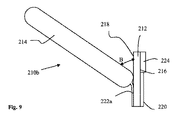
図8、図9に示すマスキングストリップに加えた修正として、マスキングストリップ210bを示す。ここでは、間隙充填材214は、角度Bが裏材212と間隙充填材214との間に形成されるように、好ましくはその長さ全体に沿って裏材212に接合される228aにおいて圧着される。角度Bで裏材212から延在する間隙充填材214を有することにより、可動部品の塗装ラインPLmの位置の再現性は更に向上する。角度Bが30°〜90°の場合(裏材212に近位の間隙充填材214の位置において裏材212と間隙充填材214との間を測定)、塗装ラインPLmにおいて、又は塗装ラインPLm領域内で間隙充填材214と間隙1の第2の内側面7の一部とは最小限接触するか、全く接触しないであろう。また、角度Bは図6に示す角度Aより大きくてよい。しかし、間隙充填材214は、間隙1の寸法に応じて、PLmから離れて、かつPLmの下にある可動自動車部品3の下面と接触してよい。圧着は、加熱及び加圧下に間隙充填材214を配置して、接合部で間隙充填材214の体積を大幅に削減することにより形成される。これにより、マスキングストリップ210bの新たな形状が作製される。
As a modification to the masking strip shown in FIGS. 8 and 9, a masking strip 210b is shown. Here, the
圧着されたマスキングストリップでは、間隙充填材214と裏材212との間に形成された角度Bが更に形成されやすくなり、したがって、間隙充填材214が間隙から外側に突出しにくいように、間隙充填材214が裏材212から更に旋回しやすくできる。また、間隙充填材214と裏材212との間に形成される角度Bが大きくなると、可動部品の下面と接触している場合の間隙充填材の圧縮が確実に最小化される。下記で詳述するように、間隙充填材214の過剰な圧縮は、PLmにおける塗料のブリッジングの原因になり得るので、望ましくない。
In the crimped masking strip, the angle B formed between the
図10は、図9のマスキングストリップの実施形態の修正を示す。ここでは、間隙充填材214が228aにおいて圧着され、その全長に沿って2つに折り畳まれ、(図10に示すように)その最遠端部214aは裏材212の第2の面218に近接するか、近位である。折り畳まれた場合、図10に示すように間隙充填材214が境界面214cに沿って自身に付着するように、間隙充填材214に接着面を設けることが可能である。間隙充填材214は、寸法を変更して、折り畳まれた場合に、十分に間隙1を充填して間隙1への塗料の流れ込みを確実に防止できるようにしてよい。
FIG. 10 shows a modification of the embodiment of the masking strip of FIG. Here,
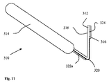
図11は、本発明の第3の実施形態によるマスキングストリップ310を示す。前述の図で示す同様の構成要素は、先頭に数字の3を付けた同一の下2桁で示す。この実施形態では、間隙充填材314は、接着剤領域320の下の裏材312の第1の面316に接着される。前述と同様に、裏材312の第1の面316の接着剤領域320は、塗装する2つの基材の間に形成される間隙の内側面にマスキングストリップ310を付着させるように機能する。裏材312は形状適合性材料で作製されており、マスキングストリップ310の使用時には、前述の実施形態と同様に、間隙充填材314が裏材312の第2の面318に近位である程度まで屈曲させることができる。当業者は、間隙充填材314が(前述のように)裏材312の接合部付近の位置で圧着され、この圧着領域を提供する他の実施形態よりも寸法が大きくてよいように図11に示す実施形態もまた修正されてよいことを理解するであろう。
FIG. 11 shows a
図2〜11を参照して上述したマスキングストリップの任意の実施形態では、使用前にマスキングストリップをディスペンサから巻き出して、必要な長さ(遮蔽する間隙及び自動車の種類に応じて異なってよい)に切断するか、ちぎってよい。任意の接着剤領域(120、220、320)を被覆する任意の保護テープ(又は別個の剥離ライナー)を除去し、マスキングストリップ(110、210、310)の裏材の接着剤領域を遮蔽する間隙の内側面に固定する。例としては、図12及び13を参照して、マスキングストリップ120の裏材112の第1の面116の接着剤領域120及びマスキングストリップ220の裏材212の第1の面216の接着剤領域220が自動車の固定部品2の内側面に貼付される。マスキングストリップ110、210は、可動部品3と固定部品2との間の間隙の湾曲に従って湾曲するように、少しずつ貼付されてよい。正しく配置された場合、マスキングストリップ110、210は、裏材の最上部、つまり最外部が間隙1の最上部8に近接するように、可動部品3と固定部品2との間の間隙内に存在する。
In any of the embodiments of the masking strip described above with reference to FIGS. 2-11, the masking strip is unwound from the dispenser before use to provide the required length (depending on the gap to be shielded and the type of vehicle). You can cut it off or tear it off. Any protective tape (or separate release liner) covering any adhesive area (120, 220, 320) is removed and a gap that shields the adhesive area on the backing of the masking strip (110, 210, 310) Secure to the inner surface of the. By way of example, with reference to FIGS. 12 and 13, the
当業者は、間隙を事実上封止し、間隙への過剰な塗料の流れ込みを防止するために塗装ラインPLmの下に間隙充填材114、214を位置付ける程度は、車体の固定部品2と可動部品3との間のランディング区域の深さ、即ち、間隙の外形寸法及び幅に応じて異なることを理解するであろう。間隙の深さは、自動車の種類に応じて約8mm〜30mm以上の範囲で異なってよい。幅は、約3mm〜11mmの範囲で異なってよい。また、固定部品2の角度は、間隙の寸法に影響する。
Those skilled in the art will position the
一部の自動車では、可動部品3の断面が不規則形状、例えば有角状、及び/又は「階段状」であってよい。同様に、固定部品2の断面は図示されない形状であるが、有角状、又は「円形状」であってよい。可動部品3の幅は、自動車の種類に応じて、2mm〜6mmの範囲で異なってよい。
In some automobiles, the cross section of the
図12は、比較的「深い」間隙を示す。間隙充填材114は塗装ラインPLmの下に配置され、間隙充填材114の厚さ(長さb)は、間隙を封止し、塗料の浸入を防止する間隙充填材114の効果に影響する。しかし、間隙充填材114の寸法は、間隙1内で可動部品3の下面に接触する程度まで、圧縮されることなく、ぴったり一致することも必要である。したがって、間隙充填材114は、間隙を画定する可動部品3の内側面の一部、PLmの領域と全く接触しないか、最小限接触することが望ましい。
FIG. 12 shows a relatively “deep” gap. The
マスキングストリップ210の間隙充填材214は、塗装ラインPLmから十分に離れた可動部品3の下にとどまるように変形してPLmにおける塗料のブリッジングを防止し、間隙充填材214が塗装する第2の基材5の領域と接触しないようにする。
The
図14も使用中のマスキングストリップ110の位置を示す。マスキングストリップ110は、好ましくは裏材112/スペーサ124の最上部が間隙8の最上部とぴったり重なるように配置される。これにより、マスキングストリップ110の裏材112/スペーサ124は、ガンGから吹き付けられる塗料が固定部品塗装ラインPLs付近の自動車の固定部品2に達しないようにする(図14)。裏材112/スペーサ124は、2面間の塗料のブリッジングが最小化されるか、防止されるように、無接着剤領域121と固定部品2との間に空隙を作製するのに役立つ。
FIG. 14 also shows the position of the
間隙充填材114は、その上隅が可動部品3の下に位置する(断面図で見た場合)寸法である。好ましくは、間隙充填材114は、PLmにおいて、又はPLm領域内で、間隙充填材114と間隙1の第2の内側面7の一部とが全く接触しないか、最小限接触する寸法である。その結果、塗装ラインPLm付近で滑らかな塗装ラインが生じる。間隙充填材114の上縁部が塗装ラインPLmの上にある場合、可動部品と間隙充填材114との間に塗料のブリッジングが生じ、起伏のある塗装縁部がもたらされるため、塗料の堆積が生じる。上述したように、間隙を事実上充填し、PLmにおいて、又はPLm領域内で、間隙1の第2の内側面7の一部と全く接触しないか、最小限接触する間隙充填材114の任意の寸法は、可動部品3の滑らかな塗装仕上げをもたらす。当然のことながら、図2のマスキングストリップ、又は実際にはスペーサなしの図6のマスキングストリップはこの結果を実現する。
The
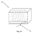
上述の全ての実施形態では、物品は予備形成され、ディスペンシングユニット160から分与可能であってよい。かかるユニットの例を図15に示す。ディスペンシングユニット160は、ある長さ(多くの場合、10メートル)のマスキングストリップ110が巻かれたリールを含む。また、当然のことながら、ディスペンシングユニット160は、吹き付け塗装を施す自動車の形状に応じて適切な種類を選択できるように、様々なバリエーションのマスキングストリップを含むか、単一の種類だけを含んでよい。このユニットの開口部によって、マスキングストリップ110(210、310)をリールから引き出して、任意の所望の長さに切断できる。ディスペンシングユニット160は、必要に応じてマスキングストリップ110を使用する、便利で空間効率の良い手段を提供する。マスキングストリップは、図15に示す軸とは異なる軸に巻かれてよい。
In all the embodiments described above, the article may be preformed and dispensed from the dispensing
図16は、本発明の第4の実施形態によるマスキングストリップの概略断面図である。マスキングストリップ400は、第1の面402及び第2の面403を有する裏材401を含み、第1の面402には、接着剤領域404が設けられて、マスキングストリップ400を間隙の内側面(図示なし)に固定する。また、マスキングストリップ400には、裏材401から延在する間隙充填材405が設けられ、塗料が間隙に流れ込まないように構成される。第1の面402には、接着剤を有さないはす縁407の形態で間隔画定手段406が設けられる。図16に図示するはす縁407は、第1の面401に対して角度Δで設けられ、Δは0°〜30°の範囲である。上述の第4の実施形態に従って、一連の4種類のサンプルを作製し、Δには、0°、8°、18°、及び30°を選択した。0°のはす縁は、事実上、変更のない第1の面401を含む。試験では、4種類のサンプル全てが許容可能な固定部品上の塗装ラインPLsをもたらし、より小さい角度Δを有するはす縁407が最良の結果をもたらすことが判明した。接着剤領域404の厚さによってはす縁407が固定部品(図示せず)から離れて配置されるため、Δが0°であっても間隔設定手段として作用することが判明した。上述の実施形態のように、第4の実施形態は予備形成された。
FIG. 16 is a schematic cross-sectional view of a masking strip according to a fourth embodiment of the present invention. The
当業者には、前述の任意の実施形態に対する様々な修正が明らかであろう。例えば、裏材の接着剤領域は、シリコン裏材に接着剤を塗布し、それを裏材に貼付してから、シリコン裏材を除去することにより実現されてよい。また、前述のマスキングストリップは、遮蔽を要する間隙を有する任意の基材の吹き付け塗装にも用いられ得ることが理解されるであろう。 Various modifications to any of the above-described embodiments will be apparent to those skilled in the art. For example, the adhesive region of the backing may be realized by applying an adhesive to the silicon backing, applying it to the backing, and then removing the silicon backing. It will also be appreciated that the aforementioned masking strip can be used for spray coating of any substrate having gaps that require shielding.
間隙充填材は、好ましくは間隙の内側面の一部と全く接触しないか、最小限接触するように構成される。これは、好ましくは塗装ラインPLmおける、又は塗装ラインPLm領域内の第2の内側面7の一部である。間隔設定手段は裏材の第1の面に配置された無接着剤領域を含んでよく、間隔設定手段はスペーサを含んでよい。 The gap filler is preferably configured to make no or minimal contact with a portion of the inner surface of the gap. This is preferably part of the second inner surface 7 in the paint line PLm or in the paint line PLm region. The spacing setting means may include an adhesive-free region disposed on the first surface of the backing, and the spacing setting means may include a spacer.
間隙充填材は、裏材の第2の面から延在してよい。裏材の断面は卵形、楕円形、矩形、三角形、正多角形、又は不規則多角形であってよい。スペーサ手段の幅は、裏材の幅とほぼ同一であってよい。しかし、スペーサの幅は、裏材の幅より小さくても、裏材の幅より大きくてもよい。 The gap filler may extend from the second side of the backing. The cross section of the backing may be oval, oval, rectangular, triangular, regular polygon, or irregular polygon. The width of the spacer means may be approximately the same as the width of the backing. However, the width of the spacer may be smaller than the width of the backing or larger than the width of the backing.
スペーサの断面は、正方形、矩形、三角形、楕円形、円形、又は正多角形若しくは不規則多角形などの多角形であってよい。また、裏材及びスペーサは、単一の材料片で形成されてよい。裏材は発泡体であってよく、及び/又はスペーサは発泡体であってよい。接着剤領域は、好ましくは接着テープを含む。また、裏材は、好ましくは可撓性であり、マスキングストリップが間隙にぴったり一致できるようにする。取り外し可能な保護テープは、裏材の接着剤領域に設けられてよい。 The cross section of the spacer may be a square, a rectangle, a triangle, an ellipse, a circle, or a polygon such as a regular polygon or an irregular polygon. Also, the backing and the spacer may be formed from a single piece of material. The backing may be a foam and / or the spacer may be a foam. The adhesive area preferably comprises an adhesive tape. Also, the backing is preferably flexible so that the masking strip can fit closely into the gap. A removable protective tape may be provided in the adhesive area of the backing.
間隙充填材は、好ましくは圧縮性かつ形状適合性であり、幾つかの実施形態では、裏材と平行に自身の上で折り畳まれてよい。間隙充填材は、好ましくは独立気泡発泡体材料を含み、その断面は矩形、正方形、楕円形、円形、三角形、又は正多角形若しくは不規則多角形などの多角形であってよい。間隙充填材は、裏材から延在する位置に圧着されてよい。 The gap filler is preferably compressible and conformable and in some embodiments may be folded on itself parallel to the backing. The gap filler preferably comprises a closed cell foam material, the cross section of which may be rectangular, square, elliptical, circular, triangular, or a polygon such as a regular or irregular polygon. The gap filler may be crimped to a position extending from the backing.
幾つかの実施形態では、裏材及びスペーサは、例えば圧着又は押出によって単一の材料片で形成されてよい。裏材及びスペーサは、複数の材料片で形成されてよい。更に、物品全体は、単一の材料片で形成されてよい。 In some embodiments, the backing and spacer may be formed of a single piece of material, for example by crimping or extrusion. The backing and the spacer may be formed of a plurality of material pieces. Further, the entire article may be formed from a single piece of material.
幾つかの実施形態では、裏材(112、212、312)及び/又はスペーサ(124、224、324)によって設けられるスペーサ手段は、塗料を吸収する、つまり、車体の一部の近位面から塗料を引き出すために形成される。スペーサ手段は、吸収性発泡体を含んでよい、及び/又は吸収物質のコーティングを含んでよい。有益には、吸収効果は、スペーサ手段付近で滑らかな塗装ラインを形成できるように提供される。スペーサ124、224、324のいずれかの上に、又はこれらの一部として追加層又はコーティングなどの他の物質を含有させて、所望に応じてその吸収特性、剥離特性、機械的特性、又は寸法を変化させてよい。
In some embodiments, the spacer means provided by the backing (112, 212, 312) and / or the spacer (124, 224, 324) absorbs paint, i.e. from the proximal face of a portion of the vehicle body. Formed to draw paint. The spacer means may comprise an absorbent foam and / or may comprise a coating of absorbent material. Beneficially, the absorption effect is provided so that a smooth paint line can be formed near the spacer means. Other materials, such as additional layers or coatings, may be included on or as part of any of
Claims (23)
第1の面及び第2の面を有する裏材であって、前記第1の面が前記マスキングストリップを前記間隙の内側面に固定する接着剤領域を有する、裏材と、
前記裏材から延在し、前記間隙に塗料が流れ込まないように構成された間隙充填材と、
を含み、
前記裏材の第1の面に、前記マスキングストリップが固定される前記間隙の内側面から前記マスキングストリップの裏材を離隔するように構成された、間隔設定手段も設けられ、前記マスキングストリップが予備形成されている、マスキングストリップ。 A masking strip for shielding the inner surface of the gap between two substrates to be coated,
A backing having a first surface and a second surface, wherein the first surface has an adhesive region that secures the masking strip to an inner surface of the gap;
A gap filler that extends from the backing and is configured to prevent paint from flowing into the gap;
Including
The first surface of the backing is also provided with spacing setting means configured to separate the backing of the masking strip from the inner surface of the gap to which the masking strip is fixed. Formed masking strip.
Applications Claiming Priority (3)
| Application Number | Priority Date | Filing Date | Title |
|---|---|---|---|
| GB1021984.8A GB2486736A (en) | 2010-12-24 | 2010-12-24 | A masking strip having a backing and a gap filler |
| GB1021984.8 | 2010-12-24 | ||
| PCT/US2011/066781 WO2012088392A1 (en) | 2010-12-24 | 2011-12-22 | Masking strip |
Publications (2)
| Publication Number | Publication Date |
|---|---|
| JP2014504545A true JP2014504545A (en) | 2014-02-24 |
| JP2014504545A5 JP2014504545A5 (en) | 2015-02-19 |
Family
ID=43599007
Family Applications (1)
| Application Number | Title | Priority Date | Filing Date |
|---|---|---|---|
| JP2013546412A Pending JP2014504545A (en) | 2010-12-24 | 2011-12-22 | Masking strip |
Country Status (7)
| Country | Link |
|---|---|
| US (1) | US9757755B2 (en) |
| EP (1) | EP2654970A4 (en) |
| JP (1) | JP2014504545A (en) |
| CN (1) | CN103298565B (en) |
| BR (1) | BR112013015670A2 (en) |
| GB (1) | GB2486736A (en) |
| WO (1) | WO2012088392A1 (en) |
Families Citing this family (7)
| Publication number | Priority date | Publication date | Assignee | Title |
|---|---|---|---|---|
| GB2486735A (en) * | 2010-12-24 | 2012-06-27 | 3M Innovative Properties Co | A masking strip having a backing and a gap filler |
| GB201316765D0 (en) | 2013-09-20 | 2013-11-06 | 3M Innovative Properties Co | Masking Tape |
| US20170232468A1 (en) * | 2016-02-10 | 2017-08-17 | John H. Tepe | Removable and re-usable painters edge useful for paint and caulking |
| US10189043B2 (en) * | 2016-10-28 | 2019-01-29 | Engineered Products And Services, Inc. | Masking device |
| WO2019232633A1 (en) * | 2018-06-07 | 2019-12-12 | Ranmi Inc. | A straight edge painting device, method, and kit |
| US11952512B2 (en) * | 2020-05-08 | 2024-04-09 | The Boeing Company | Chemical process for stripping surfaces |
| CN114919296B (en) * | 2022-05-26 | 2023-04-28 | 广东科雷明斯智能科技有限公司 | Spray printing process of lithium battery upper cover protection layer |
Citations (8)
| Publication number | Priority date | Publication date | Assignee | Title |
|---|---|---|---|---|
| GB1555808A (en) * | 1977-04-04 | 1979-11-14 | Bottrell W C J Apex Portable S | Masking tape |
| JPS63168063U (en) * | 1987-04-22 | 1988-11-01 | ||
| JPH0394969U (en) * | 1990-01-08 | 1991-09-27 | ||
| JPH08209081A (en) * | 1995-02-06 | 1996-08-13 | Kaoru Nagura | Tacky tape, spray coating using the same and device for forming the same |
| JP2000118858A (en) * | 1998-10-15 | 2000-04-25 | Nichiban Co Ltd | Masking tape forming device for coating |
| US20020022158A1 (en) * | 1996-10-11 | 2002-02-21 | Klaus-Wilhelm Voss | Plastic profile for sealing air gaps between body parts of motor vehicles |
| WO2002068556A2 (en) * | 2001-02-24 | 2002-09-06 | Jevtec Limited | Foam masking tape |
| JP2010528860A (en) * | 2007-06-11 | 2010-08-26 | スリーエム イノベイティブ プロパティズ カンパニー | Masking article comprising foam with integral skin layer |
Family Cites Families (14)
| Publication number | Priority date | Publication date | Assignee | Title |
|---|---|---|---|---|
| WO1980002391A1 (en) | 1979-04-30 | 1980-11-13 | C Stephens | Refinish painting apparatus |
| SE428649B (en) | 1982-06-07 | 1983-07-18 | Klas Jakobsson | PROCEDURE FOR SPRAY PAINTING AND A PROCEDURE FOR IMPLEMENTING THE PROCEDURE |
| US4761786A (en) | 1986-12-23 | 1988-08-02 | Spectra-Physics, Inc. | Miniaturized Q-switched diode pumped solid state laser |
| GB2298380B (en) * | 1995-02-28 | 1997-11-05 | Donald Murray Western | Masking method and device |
| AU4837696A (en) | 1995-02-28 | 1996-09-18 | Donald Murray Western | Masking method and device |
| DE29610642U1 (en) | 1996-06-18 | 1996-10-02 | Vosschemie GmbH, 25436 Uetersen | Foam strips |
| GB9807613D0 (en) * | 1998-04-09 | 1998-06-10 | Minnesota Mining & Mfg | Masking material and method |
| GB9825591D0 (en) | 1998-11-24 | 1999-01-13 | Western Donald M | Device for masking and method |
| US6887553B1 (en) * | 1999-06-23 | 2005-05-03 | 3M Innovative Properties Company | Roll of longitudinally folded masking material |
| GB0216373D0 (en) * | 2002-07-13 | 2002-08-21 | 3M Innovative Properties Co | Masking strip |
| US6921729B2 (en) * | 2002-12-31 | 2005-07-26 | 3M Innovative Properties Company | Adhesive tape |
| KR20080003437A (en) | 2005-04-22 | 2008-01-07 | 쓰리엠 이노베이티브 프로퍼티즈 컴파니 | Masking article and method of masking a substrate to be coated |
| WO2008023081A1 (en) | 2006-08-22 | 2008-02-28 | Innoecor S.L. | Tooled joint sealing strip including a lateral sheet for defining a boundary for the painting of edges and production method thereof |
| GB0622340D0 (en) * | 2006-11-09 | 2006-12-20 | 3M Innovative Properties Co | Masking article |
-
2010
- 2010-12-24 GB GB1021984.8A patent/GB2486736A/en not_active Withdrawn
-
2011
- 2011-12-22 CN CN201180062036.7A patent/CN103298565B/en not_active Expired - Fee Related
- 2011-12-22 EP EP11850584.1A patent/EP2654970A4/en not_active Withdrawn
- 2011-12-22 WO PCT/US2011/066781 patent/WO2012088392A1/en active Application Filing
- 2011-12-22 US US13/995,703 patent/US9757755B2/en not_active Expired - Fee Related
- 2011-12-22 BR BR112013015670A patent/BR112013015670A2/en not_active IP Right Cessation
- 2011-12-22 JP JP2013546412A patent/JP2014504545A/en active Pending
Patent Citations (8)
| Publication number | Priority date | Publication date | Assignee | Title |
|---|---|---|---|---|
| GB1555808A (en) * | 1977-04-04 | 1979-11-14 | Bottrell W C J Apex Portable S | Masking tape |
| JPS63168063U (en) * | 1987-04-22 | 1988-11-01 | ||
| JPH0394969U (en) * | 1990-01-08 | 1991-09-27 | ||
| JPH08209081A (en) * | 1995-02-06 | 1996-08-13 | Kaoru Nagura | Tacky tape, spray coating using the same and device for forming the same |
| US20020022158A1 (en) * | 1996-10-11 | 2002-02-21 | Klaus-Wilhelm Voss | Plastic profile for sealing air gaps between body parts of motor vehicles |
| JP2000118858A (en) * | 1998-10-15 | 2000-04-25 | Nichiban Co Ltd | Masking tape forming device for coating |
| WO2002068556A2 (en) * | 2001-02-24 | 2002-09-06 | Jevtec Limited | Foam masking tape |
| JP2010528860A (en) * | 2007-06-11 | 2010-08-26 | スリーエム イノベイティブ プロパティズ カンパニー | Masking article comprising foam with integral skin layer |
Also Published As
| Publication number | Publication date |
|---|---|
| US9757755B2 (en) | 2017-09-12 |
| BR112013015670A2 (en) | 2018-05-15 |
| CN103298565B (en) | 2016-08-17 |
| EP2654970A1 (en) | 2013-10-30 |
| WO2012088392A1 (en) | 2012-06-28 |
| US20150306621A1 (en) | 2015-10-29 |
| EP2654970A4 (en) | 2014-08-27 |
| GB201021984D0 (en) | 2011-02-02 |
| GB2486736A (en) | 2012-06-27 |
| CN103298565A (en) | 2013-09-11 |
Similar Documents
| Publication | Publication Date | Title |
|---|---|---|
| JP2014504545A (en) | Masking strip | |
| JP3026624U (en) | Masking tape with stiffening edges | |
| JP7018018B2 (en) | Surface coated filters and methods | |
| US20110016796A1 (en) | Intumescent Weatherseal | |
| CN107107530B (en) | Method for manufacturing a sheath for an elongated article | |
| JP2012533454A (en) | Method of wrapping an object with film using tape to cut the film | |
| US8327585B2 (en) | Weatherseal with removable protective coating | |
| JP2014504545A5 (en) | ||
| US9262946B2 (en) | Profiles used in generating channel letters | |
| CN114377924A (en) | Coating fire-proof shielding method and polypropylene member | |
| WO2002068556A2 (en) | Foam masking tape | |
| ES2784241T3 (en) | Masking tape | |
| US11279856B2 (en) | Filament-bearing masking tape | |
| JP2017065369A (en) | Vehicle interior component and method of manufacturing the same | |
| US20080318038A1 (en) | Masking material with liquid-repellent surface | |
| KR101837125B1 (en) | Can-shaped container having a protective inner layer | |
| US20160159060A1 (en) | Profiles used in generating channel letters | |
| KR100925534B1 (en) | Covering color tape for painting | |
| JP4550212B2 (en) | Masking tape for molding materials | |
| KR100530634B1 (en) | Auxiliary tape for painting and cover sheet having thereof | |
| WO2018080780A1 (en) | Packaged flexible film and flexible film packaging system therefor | |
| KR100893586B1 (en) | Foam masker tape and manufacturing method thereof | |
| CA2860576A1 (en) | Wrapping an object with a film using a tape for cutting the film | |
| JP2014100833A (en) | Multilayer molding | |
| EP2563523B1 (en) | Masking |
Legal Events
| Date | Code | Title | Description |
|---|---|---|---|
| A521 | Request for written amendment filed |
Free format text: JAPANESE INTERMEDIATE CODE: A523 Effective date: 20141222 |
|
| A621 | Written request for application examination |
Free format text: JAPANESE INTERMEDIATE CODE: A621 Effective date: 20141222 |
|
| A977 | Report on retrieval |
Free format text: JAPANESE INTERMEDIATE CODE: A971007 Effective date: 20150810 |
|
| A131 | Notification of reasons for refusal |
Free format text: JAPANESE INTERMEDIATE CODE: A131 Effective date: 20150818 |
|
| A601 | Written request for extension of time |
Free format text: JAPANESE INTERMEDIATE CODE: A601 Effective date: 20151117 |
|
| A521 | Request for written amendment filed |
Free format text: JAPANESE INTERMEDIATE CODE: A523 Effective date: 20160218 |
|
| A02 | Decision of refusal |
Free format text: JAPANESE INTERMEDIATE CODE: A02 Effective date: 20160524 |

