JP2014501663A - Flexible interior trim parts with cover layer - Google Patents
Flexible interior trim parts with cover layer Download PDFInfo
- Publication number
- JP2014501663A JP2014501663A JP2013548466A JP2013548466A JP2014501663A JP 2014501663 A JP2014501663 A JP 2014501663A JP 2013548466 A JP2013548466 A JP 2013548466A JP 2013548466 A JP2013548466 A JP 2013548466A JP 2014501663 A JP2014501663 A JP 2014501663A
- Authority
- JP
- Japan
- Prior art keywords
- cushion
- interior trim
- cover layer
- generally parallel
- parallel ribs
- Prior art date
- Legal status (The legal status is an assumption and is not a legal conclusion. Google has not performed a legal analysis and makes no representation as to the accuracy of the status listed.)
- Pending
Links
Images


Classifications
-
- B—PERFORMING OPERATIONS; TRANSPORTING
- B60—VEHICLES IN GENERAL
- B60R—VEHICLES, VEHICLE FITTINGS, OR VEHICLE PARTS, NOT OTHERWISE PROVIDED FOR
- B60R7/00—Stowing or holding appliances inside vehicle primarily intended for personal property smaller than suit-cases, e.g. travelling articles, or maps
- B60R7/04—Stowing or holding appliances inside vehicle primarily intended for personal property smaller than suit-cases, e.g. travelling articles, or maps in driver or passenger space, e.g. using racks
-
- B—PERFORMING OPERATIONS; TRANSPORTING
- B60—VEHICLES IN GENERAL
- B60R—VEHICLES, VEHICLE FITTINGS, OR VEHICLE PARTS, NOT OTHERWISE PROVIDED FOR
- B60R13/00—Elements for body-finishing, identifying, or decorating; Arrangements or adaptations for advertising purposes
- B60R13/02—Internal Trim mouldings ; Internal Ledges; Wall liners for passenger compartments; Roof liners
-
- B—PERFORMING OPERATIONS; TRANSPORTING
- B29—WORKING OF PLASTICS; WORKING OF SUBSTANCES IN A PLASTIC STATE IN GENERAL
- B29C—SHAPING OR JOINING OF PLASTICS; SHAPING OF MATERIAL IN A PLASTIC STATE, NOT OTHERWISE PROVIDED FOR; AFTER-TREATMENT OF THE SHAPED PRODUCTS, e.g. REPAIRING
- B29C69/00—Combinations of shaping techniques not provided for in a single one of main groups B29C39/00 - B29C67/00, e.g. associations of moulding and joining techniques; Apparatus therefore
- B29C69/02—Combinations of shaping techniques not provided for in a single one of main groups B29C39/00 - B29C67/00, e.g. associations of moulding and joining techniques; Apparatus therefore of moulding techniques only
-
- B—PERFORMING OPERATIONS; TRANSPORTING
- B60—VEHICLES IN GENERAL
- B60N—SEATS SPECIALLY ADAPTED FOR VEHICLES; VEHICLE PASSENGER ACCOMMODATION NOT OTHERWISE PROVIDED FOR
- B60N2/00—Seats specially adapted for vehicles; Arrangement or mounting of seats in vehicles
- B60N2/75—Arm-rests
- B60N2/79—Adaptations for additional use of the arm-rests
- B60N2/793—Adaptations for additional use of the arm-rests for use as storage compartments
-
- B—PERFORMING OPERATIONS; TRANSPORTING
- B60—VEHICLES IN GENERAL
- B60R—VEHICLES, VEHICLE FITTINGS, OR VEHICLE PARTS, NOT OTHERWISE PROVIDED FOR
- B60R13/00—Elements for body-finishing, identifying, or decorating; Arrangements or adaptations for advertising purposes
- B60R13/02—Internal Trim mouldings ; Internal Ledges; Wall liners for passenger compartments; Roof liners
- B60R13/0262—Mid-console liners
Abstract
概ね平行なリブ、前記リブに結合されるクッションを備えるインテリアトリム部品であり、前記インテリアトリム部品が前記概ね平行なリブの向きに概ね垂直な方向に曲がる能力がある。クッションは、一体の外皮を備える。An interior trim component comprising a generally parallel rib and a cushion coupled to the rib, wherein the interior trim component is capable of bending in a direction generally perpendicular to the direction of the generally parallel rib. The cushion has an integral outer skin.
Description
(関連出願の参照)
本出願は、2011年1月3日に提出されました、「カバー層付きフレキシブルインテリアトリム部品」という名称の、米国仮特許出願番号61/429,358の優先権と利益を主張し、その全体を参照として組み込む。
(Refer to related applications)
This application claims priority and benefit of US Provisional Patent Application No. 61 / 429,358, filed Jan. 3, 2011, entitled “Flexible Interior Trim Parts with Cover Layers”, see in its entirety Incorporate as.
本願発明は、全般的に車両用のフレキシブルインテリアトリム部品に関し、詳細には、カバー層付きフレキシブルインテリアトリム部品に関する。 The present invention relates generally to a flexible interior trim component for a vehicle, and more particularly to a flexible interior trim component with a cover layer.
車両収納コンパートメント(compartment)は、荷物及び他の小さなアイテムを収納するため、車両のインテリア全体に配置される。例えば、オーバーヘッドコンソールは、サングラス、ドライビンググラス、或いは他のアイテムを収納するための適切な収納コンパートメントを含む。他の収納コンパートメントは、中央コンソール、アームレスト、座席、ドアパネル、或いは車両インテリアの他の領域内に配置される。ある収納コンパートメントは、コンパートメントの内容物を確保し、及び/又は内容物を視覚から隠すために構成される扉を有する。 A vehicle storage compartment is placed throughout the interior of the vehicle to store luggage and other small items. For example, the overhead console includes a suitable storage compartment for storing sunglasses, driving glasses, or other items. Other storage compartments are located in the central console, armrests, seats, door panels, or other areas of the vehicle interior. Some storage compartments have doors configured to secure the contents of the compartment and / or to hide the contents from vision.
様々な扉の構造が利用されるが、巻き込み戸(tambour door)が湾曲された開口部を有する収納コンパートメント用に一般的に適切である。典型的な、巻き込み戸は、一連の交錯(interlocked)される平行な複数のリブ或いは相互にそれぞれ回転するセグメントを含む。この仕様によれば、巻き込み戸は、平行なセグメントの向きに垂直な方向にあって柔軟である。そのような構造は、巻き込み戸を、湾曲された収納コンパートメントの開口部の外縁に整合可能とする。不都合なことに、複数のリブは、一般的に概ね剛性材料から製造されており、巻き込み戸の外観面は、硬い及び/又は柔軟ではない。さらに、複数のリブの間の窪みは埃及び/又は他の汚れを集めてしまい、よって巻き込み戸の外観の評価を下げてしまう。 A variety of door configurations are utilized, but are generally suitable for storage compartments where the tambour door has a curved opening. A typical fold-out door includes a series of interlocked parallel ribs or segments that rotate with each other. According to this specification, the entrainment door is flexible in a direction perpendicular to the direction of the parallel segments. Such a structure allows the folding door to be aligned with the outer edge of the opening of the curved storage compartment. Unfortunately, the plurality of ribs are generally made from a generally rigid material, and the exterior surface of the enfolding door is not hard and / or flexible. Furthermore, the recesses between the ribs collect dust and / or other dirt, thus reducing the appearance of the entrainment door.
本発明は、トラックに沿ってインテリアトリム部品の動きを容易にするトラックを嵌め込むように構成される概ね相互に平行な複数のリブを含むインテリアトリム部品に関する。インテリアトリム部品は、さらに内側表面と、一体の外皮を有するクッションをも含むので、内側表面は、概ね平行な複数リブに結合される。インテリアトリム部品は、外観面及び裏面を有するカバー層をさらに含む。裏面は、クッションの一体の外皮に確実に取り付けられる。 The present invention relates to an interior trim component that includes a plurality of generally parallel ribs configured to fit a track that facilitates movement of the interior trim component along the track. The interior trim component further includes a cushion having an inner surface and an integral skin so that the inner surface is coupled to a plurality of generally parallel ribs. The interior trim component further includes a cover layer having an exterior surface and a back surface. The back side is securely attached to the integral outer skin of the cushion.
本発明は、さらに概ね平行な複数のリブ、前記インテリアトリム部品が前記概ね平行な複数のリブの向きに概ね垂直な方向に曲がるのを可能とするように、前記概ね平行な複数のリブに結合されるクッションを含むインテリアトリム部品に関する。クッションは、さらに少なくとも部分的にクッションの周りに配置されるカバー層も含む。カバー層は、外観面及び裏面を備え、さらにクッションは、カバー層をクッションに確実に固定するために裏面に形成される。 The present invention further includes a plurality of generally parallel ribs coupled to the generally parallel ribs to allow the interior trim component to bend in a direction generally perpendicular to the direction of the generally parallel ribs. The present invention relates to interior trim parts including cushions. The cushion further includes a cover layer disposed at least partially around the cushion. The cover layer has an exterior surface and a back surface, and the cushion is formed on the back surface to securely fix the cover layer to the cushion.
本発明は、さらに、対応する概ね平行な複数のリブを形成するための複数の概ね平行な溝を有する第1モールドに樹脂を注入することを含む、インテリアトリム部品を製造する方法に関する。インテリアトリム部品を製造する方法は、カバー層の外観面がキャビティ(cavity、空洞)の近くに配置されるように、第2モールドのキャビティをカバー層に並べることも含む。さらにインテリアトリム部品を製造する方法は、概ね平行なリブを第2モールドに移すこと、及び発泡体が概ね平行な複数のリブに接着され、さらにカバー層の裏面に接着されるクッションを形成するように第2モールドに発泡体を注入することを含む。 The present invention further relates to a method of manufacturing an interior trim component that includes injecting a resin into a first mold having a plurality of generally parallel grooves to form a corresponding plurality of generally parallel ribs. The method of manufacturing the interior trim component also includes aligning the cavity of the second mold with the cover layer such that the exterior surface of the cover layer is positioned near the cavity. Further, a method of manufacturing an interior trim component includes transferring a generally parallel rib to a second mold, and forming a cushion wherein the foam is bonded to the plurality of generally parallel ribs and further bonded to the back surface of the cover layer. Injecting a foam into the second mold.
図1は、具体例の車両10の斜視図であり、この車両10が複数の座席と中央コンソール16とを有するインテリア(interior、内装)12を含むのを示している。詳細について以下に述べるように、中央コンソール16及び/又はインテリア12内の他のエリアは、収納コンパートメントを閉鎖するフレキシブル扉のようなカバー層を有するフレキシブルインテリアトリム部品を備える。例えば、ある収納コンパートメントは、概ね平行な複数のリブを有するフレキシブルな巻き込み戸を用いる。これらの複数のリブは、トラックに嵌めこまれるように構成され、それによって収納コンパートメントの開口部に沿った巻き込み戸の動きを容易にする。巻き込み戸は、収納コンパートメントのインテリアに面する内部面を有するクッションも備える。いくつかの具現化例にあって、クッションは一体の外皮も備える。クッションの内面は、概ね平行な複数のリブに結合され、巻き込み戸は概ね平行なリブの向きに垂直な方向に収縮する。そのような構造は、巻き込み戸が湾曲された収納コンパートメントの開口部の周縁にマッチするのを可能とするので、巻き込み戸の収納コンパートメントに対する動きを容易にする。詳細を後述するように、クッションは、クッションの成形プロセスの間に形成される一体の外皮を含む。さらに、カバー層は、粘着性結合或いはクッションの成形プロセスを通して、クッションに確実に固定される。カバー層は、所望される外観を提供する間、クッションを保護する役目を果たす。
FIG. 1 is a perspective view of an
正しく理解されるように、一般的な巻き込み戸は、一連のはめ込み或いは繋がれた複数の平行なリブ或いは相互に回転する複数のセグメントを備える。巻き込み戸の複数のセグメントの回転を容易とするために、窪みが各セグメントに近接して配置される。これらの窪みは、埃及び/又は他の汚れを集めるかもしれず、よって巻き込み戸の外観を損なう。さらに、巻き込み戸は収縮するので、近接する複数のセグメントは相互に対して回転し、間にある窪みの幅を減少する。窪みの幅の減少は、近接する複数セグメントの間の望ましくない圧迫(pinch、ピンチ)ポイントを作り出す。さらに、巻き込み戸の複数のセグメントは一般的に、概ね剛性材料から形成されるので、巻き込み戸の外観面は堅い及び/又は柔軟ではない。カバー層を有するクッションの提供により、本具現化例は、これらの窪みを取り除き、さらに柔らかな外観面を作り出す。その結果、巻き込み戸のカバー層上に集まる埃或いは他の汚れは容易に除去される。さらに、複数のセグメント間の圧迫の可能性は、概ね低減されるか取り除かれる。さらに、カバー層の外観面は、巻き込み戸が搭乗者のアームレストとして機能することを可能とし、これによって分離されるアームレスト及び収納コンパートメント扉によって使用される空間を低減できる。 As can be appreciated, a typical fold-out door includes a series of inlaid or connected parallel ribs or segments that rotate relative to each other. In order to facilitate the rotation of the plurality of segments of the entrainment door, recesses are arranged close to each segment. These depressions may collect dust and / or other dirt, thus detracting from the appearance of the enfolding door. In addition, because the retracting door contracts, adjacent segments rotate relative to each other, reducing the width of the indentation in between. The reduction in the dent width creates an undesirable pinch point between adjacent segments. Furthermore, because the multiple segments of the enfolding door are generally formed from a generally rigid material, the appearance of the enfolding door is not stiff and / or flexible. By providing a cushion with a cover layer, the present embodiment removes these depressions and creates a softer appearance surface. As a result, dust or other dirt that collects on the cover layer of the entrainment door is easily removed. Furthermore, the possibility of compression between multiple segments is generally reduced or eliminated. Furthermore, the exterior surface of the cover layer allows the entrainment door to function as an armrest for the occupant, thereby reducing the space used by the armrest and storage compartment doors separated thereby.
図2は具体例の中央コンソール16の斜視図であり、中央コンソール16が図1に示される車両のインテリア内に配置されることを示す。詳細については後述するが、中央コンソール16は、カバー層を有するフレキシブル巻き込み戸によって閉鎖される収納コンパートメントを含む。図に描かれているように、中央コンソール16は、ドライバー座席14と助手席(同乗者座席)14との間の、車両のインテリア12の車両床に結合される。この構成にあって、中央コンソール16は、収納エリア及び両方の座席14の乗員用のアームレストを提供するように構成されている。中央コンソール16は、全般的に角柱状であり、前壁18、後壁20、二つの対向する全体的に同一の側壁22、及び上面24を有する。
FIG. 2 is a perspective view of an exemplary
中央コンソール16は、さらに、中央コンソール16の主ボディを形成する二つのサイドパネル26を含む。この構成にあって、各サイドパネル26は、中央コンソール16の二つの側壁22の一つと後壁20、前壁18及び上部面24のいくつかの部分を提供する。図示されるように、二つの側壁22は、凸部及び凹部の両方を有する合成の湾曲された上部輪郭(周縁)を有し、それによって持ち上げられた後壁20と下げられた前壁18の間を連結する。二つのサイドパネル26の二つの上端28は、湾曲される上部面24を形成する。上部面24は、乗員が中央コンソール16のインテリアにアクセスするのを可能とする開口部30を備える。このような構造にあって、中央コンソール16は、後壁20及び/又は上部面24の一部を形成する後部パネル32を備える。
The
本構成により、中央コンソール16は、開口位置と図示されている閉鎖位置との間を遷移するように構成される扉34を備える。扉34は、乗員に開口位置と閉鎖位置の間で、扉34をスライドさせるためのハンドル38を含む。詳細は後述するが、方向40にあって開放位置に向けて扉34をスライドすることは、中央コンソール16内に配置される収納コンパートメントのインテリアを露出させる。一構成にあって、扉34は、クッションに接続される一連の概ね平行な複数のリブを有する巻き込み戸である。一連の概ね平行な複数のリブは、二つの側壁22内のトラックに、嵌めこまれるように構成され、クッションは扉34を収縮させ、開放部30の周縁を収納させる。扉34は、所望の外観を提供し、さらにクッションを保護するためにクッションの外面に固定されるカバー層を含む。カバー層は、開口部30の周縁を収納するために、クッションをばらつきなく収縮するフレキシブル材料である。クッション及びカバー層は、さらに扉34に車両乗員用のアームレストとして機能させ、それによって分離扉34とアームレストを提供することについての空間を削減する。
With this configuration, the
この巻き込み戸は、中央コンソール16を参照して説明されているが、車両10のインテリア12全体にわたって、他の具現化例が同様の巻き込み戸を配置することを理解できる。例えば、オーバーヘッドコンソール、ドアパネル、インストルメントパネル、或いは車両のインテリア12の他の領域内に配置される収納は、カバー層を有するフレキシブル扉を含む。さらに、前述された扉に加えて、他のフレキシブルインテリアトリム部品が、同様の平行な複数のリブ、クッション及びカバー層を含む。詳細は後述するが、カバー層は、様々な材料を含み、フレキシブルインテリア部品の外観を高めるための様々な構成を有する。
Although this wrap-up door has been described with reference to the
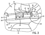
図3は図2に示された中央コンソール16の斜視図であり、フレキシブル扉34が開放位置にあることを示している。図示されるように、二つの側壁22は、方向40における扉34の動きを容易にするように構成される二つのレール或いはトラック36を備える。一つの構成にあって、二つのトラック36は、C形状の断面を備え、二つのサイドパネル26に結合されるか、二つのサイドパネル26内に一体に形成される。詳細を後述するように、巻き込み戸34の概ね平行な複数のリブは、前記トラック36に嵌り、さらに扉34を支持する複数の突起を備えるが、取り付けられたクッションは、扉34が収縮するのを可能とし、それによって開口部30の周縁を収納する。図示されるように、扉34を開放位置に動かすことは、中央コンソール16内の収納コンパートメントのインテリア42を露出する。
FIG. 3 is a perspective view of the
理解されるように、車両乗員はハンドル38を掴み、扉34を中央コンソール16の前壁18に向けて動かすことにより、扉34を閉じる。カバー層がクッションの外面に固定されるので、カバー層の外観面は、車両10のインテリア12に面する。その結果、扉34の複数セグメントによる圧迫の可能性が、概ね減少されるか取り除かれる。閉鎖位置にあると、扉34のカバー層は、適切な面をアームレストに提供する及び/又は車両インテリア12の外観を高める。
As will be appreciated, the vehicle occupant closes the
図4はカバー層付きの具体的なフレキシブル扉の斜視図であり、図2の中央コンソール内に配置される様子を示す。図示されるように、フレキシブル扉34は、パッドが詰められた基板或いはクッション46に結合される概ね平行な複数のリブ44を備える。概ね平行な複数のリブ44は、扉34を支持し、さらに扉34の開口部30にわたる扉34の動きを容易にするために、中央コンソール16のトラック36にはめ込まれるように構成される。概ね平行な複数のリブ44は各トラック36内の対応する窪みにはめ込まれるように構成される複数の突起48を備える。詳細を後述するように、概ね平行な複数のリブ44は、中央コンソール16のインテリア42に面するクッション46の面に結合されるので、統一された面を形成できる。この構成にあって、扉34は、概ね平行な複数のリブ44の向きに垂直な方向にあって収縮するので、巻き込み戸は湾曲された収納コンパートメントの開口部の周縁に合致することが可能となる。さらに、クッション46は、フレキシブル扉34の外面に、滑らかさと安定した外観を与える外観面を有するカバー層50を備える。
FIG. 4 is a perspective view of a specific flexible door with a cover layer, and shows a state where it is arranged in the central console of FIG. As shown, the
詳細について後述するように、概ね平行な複数のリブ44は、注入成形プロセスによって形成され、さらに注入成形用の適切な材料から構成される。例えば、概ね平行な複数のリブ44は、ポリプロピレン、ポリカーボネート、或いはアクリロニトリルブタジエンスチレンのような熱可塑性プラスチックポリマによって作られる。概ね平行な複数のリブ44は、他の具現化例にあって注入成形方法用の適切な他の材料によって作られることも理解される。加えて、概ね平行な複数のリブ44は、化学発泡剤及び/又は他の適切な添加剤を含む。
As will be described in detail below, the plurality of generally
一具現化例にあって、クッション46は、二つの反応型発泡コンパウンドが混合され、さらにクッション46の所望の形状を有する開口モールドに注ぎ込まれる成形プロセスによって形成される。モールドは、その後、閉じられ、混合物は、膨張され、硬化される。発泡体を注ぎ込むより前に、概ね平行な複数のリブ44をモールドの中に置くことによって、発泡体は概ね平行な複数のリブ44に硬化プロセスの間に結合される。その結果、全体にフレキシブルな部品が形成される。さらに、いくつかの具現化例にあって、モールド内の温度変動はもちろん、材料の化学的性質は、低密度発泡体クッションの外面上に高密度フレキシブル外皮を形成するのを誘導する。結果的に得られるクッション46は、概ね滑らかあるいは肌理細かい一体の外皮を有するが、巻き込み戸34が、湾曲された収納コンパートメント開口部30の周縁を収納するのを可能とするように十分なフレキシブル性を提供する。他の具現化例にあって、低密度発泡体クッションの外面のフレキシブル外皮を形成する可能性を概ね低減或いは取り除くために、様々な発泡性コンパウンド及び/又は温度が用いられる。そのような具現化例にあって、全体のクッション46は、概ね均一な低密度を有する。
In one embodiment, the
前述したように、フレキシブル扉34は、開放位置と閉鎖位置の間で、フレキシブル扉34の動きを容易にするために構成されるハンドルを備える。ハンドルは、留め具(例えば、ボルト、スクリュー、など)によって扉34に取り付けられるか、或いは概ね平行な複数のリブ44に一体に注入成形される。ハンドルが注入成形により形成されるという構成にあって、発泡体は、プラスチックハンドル全体に注ぎ込まれるか、或いは安定した握り面を提供するために、ハンドルの周りに注ぎ込まれる。同様に、ハンドルが注入成形によって形成される構成にあって、カバー層50は、一定の外観を実現するためプラスチックハンドルに固定されるか、或いは安定した握り面を提供するためにハンドルの周りに固定される。正しく理解されるように、他の具現化例は、扉の動きを制御するためのハンドルの代わりに、他の部品(例えば、ノブ、窪みなど)を配置する。例えば、一具現化例は、クッション46及びカバー層50の中に押圧或いは窪みを形成することによって、形成されるハンドルを含む。
As described above, the
部分的に分けられた外観面を有する巻き込み戸と対照的に、この具現化例のフレキシブル扉34は、相互に対して回転する分離されたセグメントを含まない。その代わりに、クッション46はフレキシブルであり、概ね平行な複数のリブ44がフレキシブル扉34の統一の視覚的な外観を維持する間、相互に対して動かさせる。さらに、フレキシブル扉34は、クッションの外面に固定されるカバー層50を備えるので、巻き込み戸34を車両の乗員のためのアームレストとして機能させる。カバー層50は、セグメントの間の、圧迫及び埃及び/他のゴミを集めてします窪みを概ね削減或いは取り除く。さらに、カバー層50は、巻き込み戸34の視覚的な外観を高める材料及び/又は構成を備える。例えば、一具現化例にあって、カバー層50は、皮革、ビニール、布(織布或いは非織布のいずれか)及び/又は様々な他の材料から製造される。図示される具現化例にあって、カバー層50は、第1材料片52と第2材料片54とを備える。さらに詳細を後述するように、第1材料片52と第2材料片54は、ステッチ58付きの縫いしろ56によって結合される。他の具現化例にあって、カバー層50は、縫いしろのない単一材料片から、或いは複数の縫いしろ56つきの3つ以上の材料片から形成されてもよい。同様に、図示された具現化例は、フレキシブル扉34を軸方向に二つに分ける縫いしろ56を示すが、他の具現化例は、円弧、角、線及び/又は他の形状を含む他の構成における縫いしろ56を有する。詳細については後述するように、カバー層50は、クッション46の外面に確実に取り付けられるので、概ね滑らかな(例えばしわのない)外観を維持する間、カバー層50はクッション46に対して収縮する。さらに詳細について後述するように、カバー層50は、粘着性結合、或いは成形プロセスを介してクッション46の外面に確実に固定される。
In contrast to a retractable door having a partially separated exterior surface, the
図5は、図4の線5−5に沿ったフレキシブル扉の第1具現化例の断面図である。図示されるように、概ね平行な複数のリブ44は、クッション46の中央コンソール16の内部42に面する、第1面60に結合される。詳細を後述するように、概ね平行な複数のリブ44は、注入成形プロセスによって形成される。正しく理解されるところによれば、注入成形プロセスは、完全な部分を形成するためにモールドの中に液体状の樹脂を注入することを含む。一たん、概ね平行な複数のリブ44が形成されると、当該リブ44は、クッション46を形成するための形状のキャビティを有するモールドの中に配置される。続いて、発泡体がモールドの中に注入される。発泡体は、膨張され、さらに硬化されるので、その発泡体は概ね平行な複数のリブ44に結合され、それによって前記リブ44と前記クッション46を含んだまとまった一つの構造が形成される。一具現化例にあって、前記モールドの中での温度変化はもちろん材料の化学的性質は、図5に示すように、低密度発泡クッション46の周りの高密度フレキシブル外皮62という構造を誘導する。そのような具現化例にあって、カバー層50は、高密度フレキシブル外皮62の外側面64に確実に取り付けられる。一具現化例にあって、カバー層50のエッジ66は、クッション46の下側に曲げられ、さらにクッション46の第1面60、或いは前記リブ44に留め具68によって固定される。例えば、留め具68は、ステープル或いはピンである。
FIG. 5 is a cross-sectional view of a first embodiment of a flexible door taken along line 5-5 in FIG. As shown, a plurality of generally
クッション46の厚さ70は、車両のアームレストとしての使用に適するクッションのついたコアを実現しながらも、巻き込み戸34の概ね平行な複数のリブ44の向きに概ね垂直な方向での曲がりを容易にするように構成される。理解されるように、厚みのあるクッション46は、快適さが高められたアームレストを提供するが、厚みのないクッション46はさらなる柔軟性を容易にする。さらに、カバー層50は、アームレストの外観としての使用に適する表面を提供するために、皮革、ビニール、或いは布のような材料から製造される。例えば、クッション46の厚さ70は、約5乃至15、6乃至13、7乃至11mmの間であるか、或いは約9mmである。さらに、一体の外皮62を有するクッション46のために、一体の外皮62の厚さ72は、クッション46が圧縮されるときに前記外皮62に収縮を可能とさせるように特に選択される。例えば、一体の外皮の厚さ72は、約2、1.5、0.5、0.3、0.2或いは0.1mm或いはさらに小さい、よりさらに薄い。さらに、カバー層50の厚さ74は、クッション46が圧縮されたときにカバー層50が収縮できるように選択される。例えば、カバー層50の厚さ74は、約2、1.5或いは1.0mm或いはそれより小さいような薄さである。
The thickness 70 of the
図6は厚みのあるクッション46、さらにはカバー層50を有する、フレキシブル扉34の第2具現化例の断面図である。前述したように、厚みのあるクッション46は、巻き込み戸34がアームレストとして用いられる構成にあって乗員の快適さを高める。同様に、カバー層50は、前述されたように、乗員の快適さを高めるために皮革、ビニール、或いは布のような材料から製造される。しかし、厚みのあるクッション46は、柔軟性を低減する。それゆえ、図示された巻き込み戸34は、巻き込み戸34が平坦面或いは大きな曲率半径を有する面に沿って動くコンソール16にて用いられる。例えば、一具現化例にあって、クッション46の厚さ76は、約16mmよりも大きい。例えば、クッション46の厚さ76は、おおよそ10乃至20、12乃至18、14乃至16mmの間であるか、或いは約15mmである。
FIG. 6 is a sectional view of a second embodiment of the
図7は、一体の外皮を除いたクッションを有するフレキシブル扉34の第3具現化例の断面図である。図示された具現化例にあって、クッション46は、高密度外皮を低密度発泡クッション46の周りに形成させない、様々な発泡コンパウンド及び/又は成形プロセスから形成される。むしろ、全体のクッション46は、概ね均一の低密度を有する。このような具現化例にあって、カバー層50は、低密度発泡クッション46の外面78に固定される。さらに詳細な説明を後述するように、カバー層50は、接着結合或いは成形プロセスを通してクッション46の外面78に固定される。
FIG. 7 is a cross-sectional view of a third embodiment of the
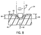
図8は、フレキシブル扉34の詳細な断面図であり、クッション46への押圧と、それに対応する一体の外皮62及びカバー層50の屈曲を示している。前述したように、クッション46は、概ね平行であり、硬い複数のリブ44に近接して配置され、負荷により変形するように構成される。結果として、巻き込み戸34が車両内の乗員のアームレストとして用いられるとき、乗員の腕の重さが、クッション46が変形すると、巻き込み戸34の広い領域に分散され、それによって乗員の快適さが増加する。一体の外皮62は、クッション46が変形すると、収縮するように構成される。同様に、カバー層50は、一体の外皮62に固定され、クッション46が変形すると、収縮するように形成され、それによってクッション46を保護し、処方の外観を提供する。
FIG. 8 is a detailed cross-sectional view of the
理解されるように、クッション46の柔らかさは、変形に対するクッションの抵抗を決定することによって測定される。様々な試験が、クッションの変形への抵抗を決定するために用いられる。例えば、凹み荷重変形(indentation force deflection、IFD)試験として知られているものは、50平方インチクッションセクションについてクッションの厚さの一部(例えば25%)を凹ませるに足りる力(荷重)を測定する。25%IFD試験に基づいて、柔らかな材料は、約6乃至24ポンドの間の範囲を有し、中程度の材料は、約24乃至36ポンドの間の範囲を有し、さらに固い材料は約36乃至45ポンドの間の範囲を有する。一具現化例にあって、クッション46は、約24乃至36ポンドの間の25%IFDを有する材料からなる。そのような柔らかさの範囲は、望ましいレベルの乗員の快適さを提供する。しかし、他の具現化例が柔らかな成分の所望される特性を実現するためより高い或いはより低い柔らかさを有するクッションを用いることを理解できる。
As will be appreciated, the softness of the
さらに、一体の外皮62は、カバー層50のために耐久性とサポートを提供し、さらに柔軟性を維持する。理解されるように、一体の外皮62の柔軟性と耐久性は、構成する材料の硬さを判断することによって測定される。硬さの一つの測定法は、凹みに対する抵抗、或いは例えばショアAスケール(Shore A scale)に示されている、デュロメータ(Durometer)である。デュロメータスケール内にて、材料は範囲に基づいて一般的に特徴つけられる。硬い或いは柔軟でないゴム状弾性物質は、だいたい90ショアAスケールよりも大きいデュロメータを有する硬さを一般的に備え、柔らかなゴム状弾性物質は、だいたい60ショアAスケール乃至90ショアAスケールのデュロメータを有する硬さを一般的に備え、過度に柔らかなゴム状弾性物質は、だいたい60ショアAスケールよりも小さいデュロメータを有する硬さを一般的に備える。一具現化例にあって、一体の外皮62はおおよそ20乃至60の間のショアAスケールのデュロメータを有する硬さを備える。そのような構造は、一体の外皮62の曲がりを容易とし、さらに耐久性と滑らかさを維持する。一体の外皮62の耐久性と滑らかさを維持することは、カバー層50をサポートするための一体の外皮62の能力を高める。さらに詳細には、耐久性があり滑らかな外皮62は、カバー層50と一体の外皮62の間の曲がり強度を増加する。他の具現化例にあって、一体の外皮62は、20ショアAスケールよりも小さいデュロメータ或いは60ショアAスケールよりも大きいデュロメータを有してもよい。
In addition, the
図8に示されるように、乗員の指80が巻き込み戸34を方向82に押圧していると、一体の外皮62とカバー層50の収縮を誘導する。図示されるように、乗員の指80が巻き込み戸34に接触するところにあって、一体の外皮62は、方向82に距離84だけ遷移され、それによってクッション46が圧縮される。同様に、カバー層50は、方向82に距離86だけ遷移される。その結果、湾曲が一体の外皮62及びカバー層50内に誘導される。一体の外皮62及びカバー層50がフレキシブルであるため、クラック変形の可能性は概ね低減されるか、取り除かれる。さらに、クッション46は、圧縮可能であるので、巻き込み戸34は、車両インテリア12内のアームレストとしての使用に最適である。
As shown in FIG. 8, when the occupant's
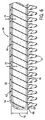
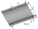
図9は、注入成形プロセスによって製造されたリブ44の斜視図であり、ランナとコネクタが取り付けられた状態を示している。前述したように、注入成形は、完成した部品を形成するために液状樹脂をモールドに注入することを含む。モールドは、所望される部品の形状を有するキャビティを含む。一具現化例にあって、モールドはキャビティを形成するために一緒に押圧される第1ハーフ及び第2ハーフを含む。加圧された液状樹脂は、一連の流動経路或いは溝を通して、キャビティ中に注入される。液状樹脂が硬化し、堅くなると、完成された部品が形成される。しかし、流動経路内に残っている残余樹脂も同様に硬化し堅くなるので、完成された部品に取り付けられる、ランナ及びコネクタが残る。
FIG. 9 is a perspective view of the
図示される注入成形された部分は、概ね平行な複数のリブ44に垂直に延びる二つの長いランナ88、及びランナ88とリブ44との間に延びる一連のコネクタ90を含む。ランナ88は、各リブ44に樹脂を供給するために構成される長手方向の流動経路によって形成され、さらに複数のコネクタ90は長手方向の流動経路とリブ44との間に延びる流動経路によって形成される。本具現化例にあって、二つのランナ88及び複数のコネクタ90は、注入成形プロセスが終わった後に一緒にリブを保持する役割を果たす。特に、二つのランナ88及び複数のコネクタ90は、前記完成された部品が第1モールドから第2モールドにクッションを形成するために移されるときに前記複数のリブの間隔及び方向を維持する。
The illustrated injection molded portion includes two
図示される注入成形された部品は、さらに二つの穴92を備える。前述したように、一具現化例にあって、巻き込み戸34は、ボルト、スクリューなどのような留め具によって巻き込み戸34に取り付けられるハンドルを備える。他の具現化例にあって、二つの穴92は、スクリューの円柱突起(ボス、bosses)を受容するように構成され、それによってスクリューが二つの穴92を通過して、ハンドルを巻き込み戸に固定するのを可能とする。二つの穴92は、パンチングプロセス或いは他の機械プロセスによって形成される。代替的に、注入成形される部品を作り出すのに用いられるモールドは、二つの穴92を形成するように構成されてもよい。さらに図示された具現化例は、二つの穴92をハンドルを巻き込み戸34に取り付けるために提供したが、他の具現化例は、二つより多い、或いは少ないホール92を備えてもよい。容易に理解されるように、他の具現化例は他の部品、例えばノブ或いは他のグリップを巻き込み戸34に取り付けるためのホール92を備えてもよい。
The illustrated injection molded part further comprises two
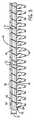
図10は、図9に示されたように、クッション46がモールドに発泡体を注ぎこむことによって形成された後、さらにカバー層50がクッション46に部分的に固定された後の、概ね平行な複数のリブ44の斜視図である。図9に示された部分が一旦形成されると、その形成された部分は、クッション46を形成するために第2モールドに移される。一具現化例によれば、第2モールドは注入成形プロセスによって形成された前記リブを受容するように構成される一連の窪みを備える。そのような具現化例にあって、前記窪みは所望のクッション46の形状を有するキャビティに整列される。二つの反応型コンパウンドは、混合されてからモールドの中に注がれるので、それによってクッション46が形成される。さらに、一具現化例にあって、モールド内の温度変化はもちろん材料の化学的性質は、高密度フレキシブル外皮62を低密度発泡クッション46の周りに形成させる。他の具現化例にあって、材料の化学的性質とモールド内の温度変化は、高密度フレキシブル外皮なしに低密度発泡性クッション46の構造を容易にする。さらに、クッション46は、発泡体が硬化したときに、前記リブ44に結合する。いったん、成形プロセスが終了すると、前記部品はモールドから取り出され、ランナ88及びコネクタ90が部品から除去される。
FIG. 10 shows a generally parallel view after the
図示のように、クッション46はさらに二つの穴94を備える。前述したように、一具現化例にあって、巻き込み戸34は、ボルト、スクリューなどのような留め具によって巻き込み戸34に取り付けられるハンドルを含む。クッション46の二つの穴94は、ハンドルを巻き込み戸34に固定するための留め具を受容するために構成される。いくつかの具現化例にあって、二つの穴94は、ドリル加工或いは切断加工のような機械加工プロセスによってあけられる。他の具現化例にあって、クッション46を形成するに用いられるモールドは、二つの穴94を形成するように形成される。理解されるように、クッション46の二つの穴は、各穴94及び92が各留め具を受容するように、注入成形部品の二つの穴92に合わせられる。さらに、クッション46は、縫いしろ56を受容するための縫いしろレリーフ96も備える。詳細を後述するように、カバー層50は、カバー層50の外観を高めると共に一つ以上の材料をつなぐ一つ以上の縫いしろ56を備える。縫いしろレリーフは96は、縫いしろ56の位置に対応するクッション46の一部を切断或いは縮充(ミリング、milling)することによって形成される。例えば、高密度フレキシブル外皮62を有する具現化例にあって、縫いしろレリーフ96は、高密度フレキシブル外皮62の一部を切り落とすことによって形成される。代替的に、クッション46を形成するために用いられるモールドは、成形プロセスの間に縫いしろレリーフ96を形成するように構成される突出部を備える。
As shown, the
前述のように、図示された具現化例は、さらに、クッション46に部分的に固定されるカバー層50を有する。さらに詳細には、カバー層50は、外観面98及び後面100を有する。前述したように、カバー層50は、例えば皮革、布地、織って作った材料、及び/又は織らずに作った材料から作られる。さらに、前述のように、カバー層50は、カバー層50を形成するために、同様にカバー層50の外観を高めるために一つ以上の材料片をつなぐ一つ以上の縫いしろ56を備える。例えば、縫いしろ56は、フレンチ縫いしろ、重ねられた縫いしろ、縛られた縫いしろ及び/又は平坦な縫いしろを含む。図示の具現化例は、第1材料片52を第2材料片54にステッチング58により固定することによって形成されるフレンチ縫いしろ56を含む。さらにフレンチ縫いしろ56は、カバー層50の後面100に突出部102を備える。カバー層50をクッション46に適用して固定すると、突出部102は、図10に示すように、縫いしろレリーフ96と整列し、さらに縫いしろレリーフ96によって受容される。理解されるように、そのような構成は、カバー層50の外観面98に滑らかさと高められた外観を与える。
As previously described, the illustrated implementation further includes a
前述したように、カバー層50は、粘着性の結合によって、クッション46に固定される。図示される具現化例は、クッション46に部分的に固定されるカバー層50を示す。いくつかの具現化例にあって、粘着性の結合は、ポリ酢酸ビニル、ポリビニルピロリドン、シアノアクリレート、エポキシ樹脂などのような接着剤を含む。理解されるように、ある粘着は、カバー層50を製造するために用いられる材料(例えば、皮革、ビニール、布地など)に依存した様々なアプリケーションに好ましい。代替的に、カバー層50は、さらに後述するような成形プロセスによってクッション46に固定される。
As described above, the
前述したように、一具現化例にあって、巻き込み戸34は、ボルト、スクリューなどのような留め具によって巻き込み戸34に取り付けられるハンドルを含む。図示される具現化例にあって、カバー層50は、複数の穴104を備える。複数の穴104は、ハンドルを巻き込み戸34に固定するための留め具を受容するために構成される。前記穴104は、切断加工又は打ち抜き加工のような機械加工によって形成される。理解されるように、前記穴104を形成するために用いられる機械加工は、カバー層50を製造するために用いられる材料(例えば、皮革、ビニール、布地など)に依存して異なる。さらに前記穴104は、クッション46の前記二つの穴94及び注入成形された部品の前記二つの穴92と整列され、よって各穴104、94及び92はそれぞれの留め具を受容する。
As described above, in one embodiment, the
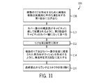
図11は、フレキシブルドア34を形成するために用いられる具体的なプロセス106のプロセスフロー図である。第1に、ブロック108で示されるように、複数の平行なリブ44を形成するために樹脂を複数の概ね平行な溝を有する第1モールドに注ぎ込む。前述したように、樹脂は、ポリプロピレン、ポリカーボネート、或いはアクリロニトリルブタジエンスチレンのような熱可塑性プラスチックポリマである。しかし、理解されるように、注入成形用にふさわしい適切な樹脂が他の具現化例に用いられる。適切な樹脂は、操作の間、巻き込み戸34を支持するのに十分な曲がり抵抗を有する前記平行なリブ44を形成するように選択される。
FIG. 11 is a process flow diagram of a
続いて、クッション46の形状を画定するキャビティを有する第2モールドが、ブロック110によって示されるように、カバー層50に並べられる。さらに詳しくは、カバー層50の外観面98は、キャビティの内面に近接して配置される。前述のように、カバー層50は、例えば、皮革、ビニール、布地、織られた材料、及び/又は織られない材料にて製造される。
Subsequently, a second mold having a cavity that defines the shape of the
第1樹脂が硬化し、及び/又は硬くなると、ブロック112に示されるように、前記平行なリブ44は、クッションを形成するために第2モールドに移される。前述のように、前記平行なリブ44は、所望される向きにて前記平行なリブ44を保持し、かつ前記リブ間のスペースを維持するように構成される。次に、前記平行なリブ44は、単一のユニットとして第1モールドから第2モールドに移される。第2モールドは、前記平行な複数のリブ44を受容するように構成される窪みを備え、それによってクッションの形状を画定するキャビティにリブ44を整列する。発泡体がブロック114で示すように、クッションを形成するために第2モールドに注ぎ込まれる。前述のように、二つの反応型コンパウンドは、混合されてから前記モールドの中に注ぎ込まれ、それによってクッション46を形成する。さらに、クッション46は、発泡体が硬化すると、前記リブ44さらにはカバー層50の後面98に結合される。いったん、成形プロセスが完了すると、巻き込み戸34は、モールドから取り出される。最終的に、ブロック116にて示されるように、ランナ88及びコネクタ90は、完了した巻き込み戸34から取り除かれる。
As the first resin hardens and / or hardens, as shown in
本発明の特徴及び具現化例のみを図示し説明してきたが、理解されるように、他の具現化例として、特許請求の範囲に列挙される発明の主題の新規の教示及び有利な点から逸れることなく、多くの変形及び変化が当業者によって行なわれる(例えば、サイズのバリエーション、寸法、構造、様々な素子の形状及び比率、パラメータの値(例えば、温度、圧力など)、取り付け配置、材料の使用、色、向きなど)。いかなるプロセス或いは方法ステップの順番或いはシーケンスは、他の具現化により、変更或いは再シーケンスされる。それゆえ、添付の特許請求の範囲が発明の思想内におさまるように、全ての更新及び変更をカバーすることを意図していることが理解される。さらに、具現化例の簡潔な説明を提供するための努力にあって、実際に行われる全ての特徴は、記載されていない(すなわち、本発明を実行する現在、考慮されるベストモードに関係ないようなもの、或いは請求された発明を可能とするのに関係ないようなもの)。いかなる実際の実行の開発にあって、エンジニアリング或いはデザインプロジェクトとして、多くの実行の特別な決定が行なわれることを理解すべきである。そのような開発の努力は、複雑である時間を要するが、それにもかかわらず、開示の利益を有する当業者にとって、過度の実験をせずに、設計、製造、及び製作のルーティンの仕事となる。 While only the features and implementations of the present invention have been illustrated and described, as will be appreciated, other implementations may be used from the novel teachings and advantages of the claimed subject matter as recited in the claims. Many variations and modifications will be made by those skilled in the art without deviation (eg, size variations, dimensions, structure, various element shapes and ratios, parameter values (eg, temperature, pressure, etc.), mounting arrangements, materials Use, color, orientation, etc.). The order or sequence of any process or method steps may be changed or resequenced according to other implementations. It is therefore understood that the appended claims are intended to cover all updates and modifications so as to fall within the spirit of the invention. Further, in an effort to provide a concise description of the implementation, all features that are actually made are not described (i.e., not relevant to the best mode currently under consideration for carrying out the invention). Or something not related to enabling the claimed invention). It should be understood that in the development of any actual execution, many execution specific decisions are made as engineering or design projects. Such development efforts take time to be complex, but nevertheless, for those skilled in the art having the benefit of the disclosure, the routine work of design, manufacture, and fabrication without undue experimentation .
Claims (20)
内面と一体の外皮を有し、前記内面が前記複数の概ね平行なリブに結合されるクッションと、
外観面及び後面を有し、前記後面が前記クッションの前記一体の外皮に固定されるカバー層と
を備えるインテリアトリム部品。 A plurality of generally parallel ribs configured to be fitted into the track for facilitating movement of interior trim components along the track;
A cushion having an outer skin integral with an inner surface, wherein the inner surface is coupled to the plurality of generally parallel ribs;
An interior trim component having an exterior surface and a rear surface, wherein the rear surface is fixed to the integral outer skin of the cushion.
前記インテリアトリム部品が前記複数の概ね平行なリブの向きに概ね垂直な方向に曲がるのを可能とするように、前記複数の概ね平行なリブに結合されるクッションと、
前記クッションに少なくとも部分的に配置され、外観面と後面を備えるカバー層と
を備え、
前記クッションは、前記複数の概ね平行なリブを前記クッションに固定するために前記複数の概ね平行なリブに成形される、インテリアトリム部品。 A plurality of generally parallel ribs;
A cushion coupled to the plurality of generally parallel ribs to allow the interior trim component to bend in a direction generally perpendicular to the direction of the plurality of generally parallel ribs;
A cover layer that is at least partially disposed on the cushion and comprises an exterior surface and a rear surface;
The interior trim component, wherein the cushion is molded into the plurality of generally parallel ribs to secure the plurality of generally parallel ribs to the cushion.
カバー層の外観面がキャビティに近接して配置されるように、カバー層に第2モールドのキャビティを整列すること、
前記複数の概ね平行なリブを前記第2モールドに移すこと、
前記発泡体が前記複数の概ね平行なリブ及び前記カバー層の後面に結合されるクッションを形成するように発泡体を前記第2モールドに注入すること
を備えるインテリアトリム部品を製造する方法。 Injecting resin into a first mold having a plurality of generally parallel grooves to form a corresponding plurality of generally parallel ribs;
Aligning the cavity of the second mold with the cover layer such that the exterior surface of the cover layer is positioned proximate to the cavity;
Transferring the plurality of generally parallel ribs to the second mold;
Injecting foam into the second mold such that the foam forms a cushion bonded to the plurality of generally parallel ribs and a rear surface of the cover layer.
Applications Claiming Priority (3)
| Application Number | Priority Date | Filing Date | Title |
|---|---|---|---|
| US201161429358P | 2011-01-03 | 2011-01-03 | |
| US61/429,358 | 2011-01-03 | ||
| PCT/US2012/020105 WO2012094340A1 (en) | 2011-01-03 | 2012-01-03 | Flexible interior trim component with a cover layer |
Publications (1)
| Publication Number | Publication Date |
|---|---|
| JP2014501663A true JP2014501663A (en) | 2014-01-23 |
Family
ID=45524999
Family Applications (1)
| Application Number | Title | Priority Date | Filing Date |
|---|---|---|---|
| JP2013548466A Pending JP2014501663A (en) | 2011-01-03 | 2012-01-03 | Flexible interior trim parts with cover layer |
Country Status (7)
| Country | Link |
|---|---|
| US (1) | US20140021733A1 (en) |
| EP (1) | EP2661383B1 (en) |
| JP (1) | JP2014501663A (en) |
| KR (1) | KR20140030130A (en) |
| CN (1) | CN103347740B (en) |
| BR (1) | BR112013017193A2 (en) |
| WO (1) | WO2012094340A1 (en) |
Families Citing this family (10)
| Publication number | Priority date | Publication date | Assignee | Title |
|---|---|---|---|---|
| US9481323B2 (en) | 2008-12-03 | 2016-11-01 | Jason M. Hipshier | Flexible interior trim component having a smooth surface |
| CN104812626A (en) * | 2012-11-01 | 2015-07-29 | 江森自控科技公司 | Flexible interior trim component |
| EP2848404B1 (en) * | 2013-09-13 | 2017-11-29 | Faurecia Innenraum Systeme GmbH | Roller shutter and storage compartment comprising said roller shutter |
| US10336228B2 (en) * | 2017-03-14 | 2019-07-02 | Ford Global Technologies Pllc | Four-component armrest assembly and method of manufacturing same |
| US10308151B2 (en) | 2017-04-11 | 2019-06-04 | Ford Global Technologies, Llc | Armrest assembly and unitary armrest subassembly having a support substrate and resilient web secured together by mechanical fastening feature |
| US10232802B2 (en) | 2017-08-02 | 2019-03-19 | Faurecia Interior Systems, Inc. | Vehicle interior panel with compressible layer of non-uniform thickness |
| US10737636B2 (en) * | 2018-01-31 | 2020-08-11 | Shanghai Yanfeng Jinqiao Automotive Trim Systems Co. Ltd. | Vehicle interior component |
| CN109204159A (en) * | 2018-09-19 | 2019-01-15 | 苏州顺时特机械科技有限公司 | A kind of multi-functional sizing plastic pad |
| US11904811B2 (en) | 2021-03-01 | 2024-02-20 | Ford Global Technologies, Llc | Storage assembly for a vehicle |
| FR3131733A1 (en) * | 2022-01-13 | 2023-07-14 | Airbus Atlantic Sas | Element for covering an edge of an aeronautical seat shell, method of manufacturing and method of installing such an element |
Citations (10)
| Publication number | Priority date | Publication date | Assignee | Title |
|---|---|---|---|---|
| JPH01162839U (en) * | 1988-05-02 | 1989-11-13 | ||
| JPH09193952A (en) * | 1996-01-18 | 1997-07-29 | Kojima Press Co Ltd | Lid of container and its manufacture |
| US20060186696A1 (en) * | 2005-02-10 | 2006-08-24 | Lisa Draxlmaier Gmbh | Roller blind with soft surface |
| JP2008013130A (en) * | 2006-07-07 | 2008-01-24 | Kasai Kogyo Co Ltd | Sticking method for skin having stitch line |
| US7581773B2 (en) * | 2005-05-19 | 2009-09-01 | Lisa Dräxlmaier GmbH | Roller blind with curved surface |
| JP2010510135A (en) * | 2006-11-21 | 2010-04-02 | ジョンソン コントロールズ テクノロジー カンパニー | Flexible interior parts |
| US20100133866A1 (en) * | 2008-12-03 | 2010-06-03 | Johnson Controls Technology Company | Flexible interior trim component having a smooth surface |
| JP2010200855A (en) * | 2009-02-27 | 2010-09-16 | Inoac Corp | Armrest |
| JP2010201983A (en) * | 2009-02-27 | 2010-09-16 | Inoac Corp | Cover member |
| JP2010215131A (en) * | 2009-03-17 | 2010-09-30 | Inoac Corp | Vehicular interior member |
Family Cites Families (6)
| Publication number | Priority date | Publication date | Assignee | Title |
|---|---|---|---|---|
| JPS6475224A (en) * | 1987-09-18 | 1989-03-20 | Hayashi Telempu Kk | Manufacture of composite trimming material for vehicle |
| JP2005066219A (en) * | 2003-08-27 | 2005-03-17 | Toyo Tire & Rubber Co Ltd | Seat for vehicle |
| JP4169707B2 (en) * | 2004-02-05 | 2008-10-22 | トヨタ車体株式会社 | Assembly structure of vehicle interior parts |
| JP2006062556A (en) * | 2004-08-27 | 2006-03-09 | Kasai Kogyo Co Ltd | Decoration sheet material |
| DE102005019884B3 (en) * | 2005-04-28 | 2006-07-13 | Lisa Dräxlmaier GmbH | Blind flat with surrounding surface for use on motor vehicle has guide for blind using guide elements and detachable blind section to cover window and which can pivot from the plane spanning the opening |
| US7721926B2 (en) * | 2005-11-08 | 2010-05-25 | Nissan Technical Center Northe America, Inc. | Vehicle storage structure |
-
2012
- 2012-01-03 JP JP2013548466A patent/JP2014501663A/en active Pending
- 2012-01-03 US US13/978,125 patent/US20140021733A1/en not_active Abandoned
- 2012-01-03 BR BR112013017193A patent/BR112013017193A2/en not_active IP Right Cessation
- 2012-01-03 EP EP12700879.5A patent/EP2661383B1/en active Active
- 2012-01-03 CN CN201280007312.4A patent/CN103347740B/en active Active
- 2012-01-03 KR KR1020137020562A patent/KR20140030130A/en not_active Application Discontinuation
- 2012-01-03 WO PCT/US2012/020105 patent/WO2012094340A1/en active Application Filing
Patent Citations (11)
| Publication number | Priority date | Publication date | Assignee | Title |
|---|---|---|---|---|
| JPH01162839U (en) * | 1988-05-02 | 1989-11-13 | ||
| JPH09193952A (en) * | 1996-01-18 | 1997-07-29 | Kojima Press Co Ltd | Lid of container and its manufacture |
| US20060186696A1 (en) * | 2005-02-10 | 2006-08-24 | Lisa Draxlmaier Gmbh | Roller blind with soft surface |
| US7588280B2 (en) * | 2005-02-10 | 2009-09-15 | Lisa Dräxlmaier GmbH | Roller blind with soft surface |
| US7581773B2 (en) * | 2005-05-19 | 2009-09-01 | Lisa Dräxlmaier GmbH | Roller blind with curved surface |
| JP2008013130A (en) * | 2006-07-07 | 2008-01-24 | Kasai Kogyo Co Ltd | Sticking method for skin having stitch line |
| JP2010510135A (en) * | 2006-11-21 | 2010-04-02 | ジョンソン コントロールズ テクノロジー カンパニー | Flexible interior parts |
| US20100133866A1 (en) * | 2008-12-03 | 2010-06-03 | Johnson Controls Technology Company | Flexible interior trim component having a smooth surface |
| JP2010200855A (en) * | 2009-02-27 | 2010-09-16 | Inoac Corp | Armrest |
| JP2010201983A (en) * | 2009-02-27 | 2010-09-16 | Inoac Corp | Cover member |
| JP2010215131A (en) * | 2009-03-17 | 2010-09-30 | Inoac Corp | Vehicular interior member |
Also Published As
| Publication number | Publication date |
|---|---|
| WO2012094340A1 (en) | 2012-07-12 |
| EP2661383B1 (en) | 2017-10-25 |
| BR112013017193A2 (en) | 2016-09-20 |
| CN103347740A (en) | 2013-10-09 |
| EP2661383A1 (en) | 2013-11-13 |
| CN103347740B (en) | 2016-07-13 |
| US20140021733A1 (en) | 2014-01-23 |
| KR20140030130A (en) | 2014-03-11 |
Similar Documents
| Publication | Publication Date | Title |
|---|---|---|
| JP2014501663A (en) | Flexible interior trim parts with cover layer | |
| JP5555807B2 (en) | Flexible interior trim parts with integral leather exterior surface | |
| US20150258939A1 (en) | Flexible interior trim component | |
| EP1844978B1 (en) | Interior trim for automobile | |
| JP5911894B2 (en) | Vehicle interior storage pocket | |
| US9481323B2 (en) | Flexible interior trim component having a smooth surface | |
| US7425029B2 (en) | Integral cushioned trim panel for a vehicle | |
| KR20090122191A (en) | Localized deep soft area of a trim panel | |
| JP2004231030A (en) | Interior parts for automobile manufacturing method thereof, and molding die for the same | |
| WO2009012313A1 (en) | Method of tensioning coverstock and forming vehicle interior components using retractable pins | |
| JP6650360B2 (en) | Skin-integrated foam molded product | |
| JP6650361B2 (en) | Skin-integrated foam molded product | |
| US20090085237A1 (en) | Method and apparatus for tensioning coverstock and forming vehicle interior components | |
| JP7330251B2 (en) | seat pad for vehicle | |
| JP4884203B2 (en) | Manufacturing method of console lid | |
| JPH07115619B2 (en) | Vehicle interior parts and manufacturing method thereof | |
| JP2006001213A (en) | Seat pad manufacturing method |
Legal Events
| Date | Code | Title | Description |
|---|---|---|---|
| A621 | Written request for application examination |
Free format text: JAPANESE INTERMEDIATE CODE: A621 Effective date: 20130902 |
|
| A977 | Report on retrieval |
Free format text: JAPANESE INTERMEDIATE CODE: A971007 Effective date: 20140717 |
|
| A131 | Notification of reasons for refusal |
Free format text: JAPANESE INTERMEDIATE CODE: A131 Effective date: 20140722 |
|
| A601 | Written request for extension of time |
Free format text: JAPANESE INTERMEDIATE CODE: A601 Effective date: 20141021 |
|
| A602 | Written permission of extension of time |
Free format text: JAPANESE INTERMEDIATE CODE: A602 Effective date: 20141028 |
|
| A521 | Written amendment |
Free format text: JAPANESE INTERMEDIATE CODE: A523 Effective date: 20150120 |
|
| A131 | Notification of reasons for refusal |
Free format text: JAPANESE INTERMEDIATE CODE: A131 Effective date: 20150728 |
|
| A601 | Written request for extension of time |
Free format text: JAPANESE INTERMEDIATE CODE: A601 Effective date: 20151027 |
|
| A02 | Decision of refusal |
Free format text: JAPANESE INTERMEDIATE CODE: A02 Effective date: 20160329 |