JP2014240102A - Workpiece fixing device of machine tool - Google Patents
Workpiece fixing device of machine tool Download PDFInfo
- Publication number
- JP2014240102A JP2014240102A JP2013122913A JP2013122913A JP2014240102A JP 2014240102 A JP2014240102 A JP 2014240102A JP 2013122913 A JP2013122913 A JP 2013122913A JP 2013122913 A JP2013122913 A JP 2013122913A JP 2014240102 A JP2014240102 A JP 2014240102A
- Authority
- JP
- Japan
- Prior art keywords
- fixed
- clamp member
- workpiece
- side clamp
- arc
- Prior art date
- Legal status (The legal status is an assumption and is not a legal conclusion. Google has not performed a legal analysis and makes no representation as to the accuracy of the status listed.)
- Pending
Links
Images


Abstract
Description
本発明は、工作機械のテーブル上に設置される固定側クランプ部材および可動側クランプ部材でワークを締付け固定し、ワークに研磨、切削等の機械加工を施すようにした工作機械のワーク固定装置に関する。 The present invention relates to a workpiece fixing device for a machine tool in which a workpiece is clamped and fixed by a fixed-side clamp member and a movable-side clamp member installed on a table of the machine tool, and machining such as polishing and cutting is performed on the workpiece. .
従来、この種の工作機械のワーク固定装置は、平坦な固定面を有する固定側クランプ部材および可動側クランプ部材でワークを締付け固定するものが一般的である。しかしながら、機械加工が施されるワークの被固定面は平坦なものだけではなく、傾斜面や曲面のように複雑な形状を有するものがある。 2. Description of the Related Art Conventionally, a workpiece fixing device of this type of machine tool generally uses a fixed-side clamp member having a flat fixing surface and a movable-side clamp member to clamp and fix the workpiece. However, the fixed surface of the workpiece to be machined is not only flat but also has a complicated shape such as an inclined surface or a curved surface.
その場合には、平坦な固定面を有する固定側クランプ部材および可動側クランプ部材ではワークの締付け固定が不十分となる。そして、ワークが機械加工時に外れたり、回転してしまい、水平面の研磨等の機械加工が良好に行われなくなる問題があった。 In that case, the fixed clamping member and the movable clamping member having a flat fixed surface are insufficiently clamped and fixed to the workpiece. In addition, there is a problem that the workpiece is detached or rotated at the time of machining, and machining such as polishing of a horizontal surface is not performed well.
そこで、固定側クランプ部材および可動側クランプ部材のうち少なくとも一方のクランプ部材を、固定部材と固定部材に対して回転可能な可動部材とから構成し、可動部材をワークの形状に合わせて回転させてワークを固定するようにしたもの(例えば、特許文献1および特許文献2参照。)や、固定側クランプ部材および可動側クランク部材の固定面をワークの形状に合わせてV字状やT字状にしたもの(例えば、特許文献3参照。)が提案されている。
Therefore, at least one of the fixed-side clamp member and the movable-side clamp member is composed of a fixed member and a movable member that can rotate with respect to the fixed member, and the movable member is rotated according to the shape of the workpiece. The fixed surface of the fixed clamp member and the movable crank member is made into a V shape or T shape in accordance with the shape of the workpiece (for example, refer to
上述した工作機械のワーク固定装置において、クランプ部材を固定部材と可動部材の2部材に分割するものでは、クランプ部材の構造が複雑となり、コスト高となるとともに、クランプ部材自体の強度が低下する心配があった。また、クランプ部材の固定面の形状をワークの形状に合わせるものでは、クランプ部材の構造が複雑となり、コスト高となるばかりでなく、ワークの形状に合わせた複数のクランプ部材を用意し、使い分ける必要があり、大変不経済であった。 In the workpiece fixing device for a machine tool described above, if the clamp member is divided into two members, that is, a fixed member and a movable member, the structure of the clamp member becomes complicated and the cost increases, and the strength of the clamp member itself may be reduced. was there. In addition, when the shape of the clamp member's fixed surface is matched to the shape of the workpiece, the structure of the clamp member is complicated and the cost is increased, and a plurality of clamp members that match the shape of the workpiece must be prepared and used separately. It was very uneconomical.
また、複雑な形状のワークを固定する際、固定型クランプ部材の固定面と可動型クランプ部材の固定面とが平行にならず、固定面同士が傾いた状態にてワークを締付け固定する場合がある。この状態にてワークに研磨、切削等の機械加工を施すと、締付け時の力が固定面同士の広く開いた方向へと逃げ、ワークもその方向へ移動し、機械加工中に両クランプ部材間からワークが抜け落ちてしまうという問題があった。 In addition, when fixing a workpiece with a complicated shape, the fixed surface of the fixed clamp member and the fixed surface of the movable clamp member may not be parallel, and the workpiece may be tightened and fixed with the fixed surfaces tilted. is there. If the workpiece is subjected to machining such as grinding or cutting in this state, the clamping force will escape in the direction in which the fixed surfaces are wide open, and the workpiece will also move in that direction. There was a problem that the work would fall out.
本発明は、ワークの被固定面が傾斜面や曲面等の複雑な形状であっても、平坦な固定面を有する固定側クランプ部材および可動側クランプ部材を用いてワークをしっかりと固定し、ワークの外れや回転を防止できるようにすることを目的とする。 The present invention firmly fixes a work using a fixed-side clamp member and a movable-side clamp member having a flat fixed surface, even if the fixed surface of the work is a complicated shape such as an inclined surface or a curved surface. It aims to be able to prevent slipping off and rotation.
本発明の工作機械のワーク固定装置は、工作機械のテーブル上に設置され、それぞれ平担な固定面を有する固定側クランプ部材および可動側クランプ部材でワークを締付け固定し、前記ワークに機械加工を施すようにした工作機械のワーク固定装置であって、前記固定側クランプ部材を前記テーブルに固定する固定手段と、前記固定側クランプ部材と前記テーブルとの当接面には、円弧状突起と、前記円弧状突起が摺動自在な円弧状溝とが係合して設けられ、前記円弧状突起及び前記円弧状溝は、前記固定手段の取付け位置を中心とした同心円上に設けられることを特徴とする。 A workpiece fixing device for a machine tool according to the present invention is installed on a table of a machine tool, and a workpiece is clamped and fixed by a fixed clamp member and a movable clamp member each having a flat fixing surface, and the workpiece is machined. A workpiece fixing device for a machine tool, wherein a fixing means for fixing the fixed-side clamp member to the table, an arc-shaped protrusion on a contact surface between the fixed-side clamp member and the table, The arcuate protrusion is provided in engagement with a freely slidable arcuate groove, and the arcuate protrusion and the arcuate groove are provided on a concentric circle centered on the mounting position of the fixing means. And
本発明の工作機械のワーク固定装置では、一対のクランプ部材のうち、固定側クランプ部材の底面に設けられた円弧状突起または円弧状溝と、テーブルに設けられた円弧状溝または円弧状突起とを利用して、固定用クランプ部材をテーブル上で回転させる。この構造により、固定側クランプ部材の固定面がワークの被固定面に密着するように設定した状態で、固定側クランプ部材をテーブルに固定することができる。 In the workpiece fixing device for a machine tool according to the present invention, of the pair of clamp members, an arc-shaped protrusion or arc-shaped groove provided on the bottom surface of the fixed-side clamp member, an arc-shaped groove or arc-shaped protrusion provided on the table, and Is used to rotate the clamping member on the table. With this structure, the fixed-side clamp member can be fixed to the table in a state where the fixed surface of the fixed-side clamp member is set to be in close contact with the fixed surface of the workpiece.
このため、ワークの被固定面が傾斜面や曲面等の複雑な形状であっても、それぞれ平坦な固定面を有する固定側クランプ部材および可動側クランプ部材によってワークをしっかりと締付け固定することができ、ワークが加工時に外れたり、回転しないようにできる。 For this reason, even if the work surface to be fixed has a complicated shape such as an inclined surface or a curved surface, the work can be firmly tightened and fixed by the fixed side clamp member and the movable side clamp member each having a flat fixed surface. The workpiece can be prevented from coming off or rotating during processing.
また、工作機械のワーク固定装置では、固定側クランプ部材の固定面の端部に可動側クランプ部材側に突出した突起片が設けられている。この構造により、ワークの被固定面がさらに複雑な形状であっても、ワークの形状に合わせて回転させた固定側クランプ部材の固定面と突起片とをワークの被固定面に接触させ、ワークの抜け止めを図りながら、ワークをしっかりと締付け固定することができる。 Moreover, in the workpiece fixing device of the machine tool, a protruding piece that protrudes toward the movable clamp member is provided at the end of the fixed surface of the fixed clamp member. With this structure, even if the work surface to be fixed has a more complicated shape, the fixed surface of the clamp member on the fixed side and the protruding piece, which are rotated according to the shape of the work, are brought into contact with the work surface to be fixed. The work can be firmly tightened and fixed while preventing the screw from coming off.
また、固定側クランプ部材の回転は、固定側クランプ部材とテーブルとの固定手段の取付け位置を中心として行われるため、固定手段を脱着するだけで、固定側クランプ部材の回転位置の設定作業を簡単に行うことができる。 In addition, since the rotation of the fixed side clamp member is performed centering on the mounting position of the fixing means between the fixed side clamp member and the table, it is easy to set the rotational position of the fixed side clamp member simply by detaching the fixing means. Can be done.
従来のように、クランプ部材を固定部材と可動部材の2部材に分割したり、クランプ部材の固定面を複雑な形状に加工するものに比べて、クランプ部材自体の強度が低下する問題がない。そして、クランプ部材が安価に構成できるとともに、既存のクランプ部材を改良して使用することもでき、経済的である。 There is no problem that the strength of the clamp member itself is reduced as compared with the conventional case where the clamp member is divided into two members, a fixed member and a movable member, or the fixed surface of the clamp member is processed into a complicated shape. And while being able to comprise a clamp member cheaply, the existing clamp member can also be improved and used, and it is economical.
さらにまた、可動側クランプ部材は、テーブル上に摺動自在に取付けられた可動部と、この可動部にボルトにて取付けられるクランプ部とを有し、可動部にはクランプ部の取付け位置をワークの形状に合わせて変更するための複数のボルト取付け穴を備えている。 Furthermore, the movable side clamp member has a movable part slidably mounted on the table, and a clamp part attached to the movable part with a bolt. A plurality of bolt mounting holes for changing in accordance with the shape is provided.
この構造により、ワークがより複雑な形状であっても、ワークの形状に合わせて回転させた固定側クランプ部材の固定面と、ワークの形状に合わせて取付け位置を設定した可動側クランプ部材の固定面と、突起片とをワークの被固定面に接触させ、ワークの抜け止めを図りながら、ワークをより強固に締付け固定することができる。 With this structure, even if the workpiece has a more complicated shape, the fixed surface of the fixed-side clamp member rotated according to the shape of the workpiece and the fixing of the movable-side clamp member with the mounting position set according to the shape of the workpiece The workpiece can be tightened and fixed more firmly while bringing the surface and the protruding piece into contact with the fixed surface of the workpiece and preventing the workpiece from coming off.
以下、本発明の一実施の形態に係る工作機械のワーク固定装置に関し、図1ないし図7に基づき詳細に説明する。 Hereinafter, a work fixing device for a machine tool according to an embodiment of the present invention will be described in detail with reference to FIGS.
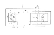
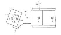
図1は、工作機械のワーク固定装置1の概略構造を示す平面図である。図2は、図1に示すワーク固定装置の正面図である。図3は、図1に示すワーク固定装置1の分解斜視図である。図4は、図1に示すワーク固定装置の第1の使用状態を示す説明図である。図5は、図1に示すワーク固定装置の第2の使用状態を示す説明図である。図6は、図1に示すワーク固定装置の第3の使用状態を示す説明図である。図7は、図1に示すワーク固定装置の第4の使用状態を示す説明図である。
FIG. 1 is a plan view showing a schematic structure of a
図1および図2に示す如く、工作機械のワーク固定装置1は、研磨や切削等の加工を行う工作機械(図示せず)の作業台に電磁石等を用いて固定されるテーブル2を備えている。そして、テーブル2上には、ワーク(被加工物)を締付け固定するための固定側クランプ部材3及び可動側クランプ部材4が取付けられている。
As shown in FIGS. 1 and 2, a
固定側クランプ部材3は基部3Aと、基部3Aと一体のクランプ部3Bとからなり、全体として直方体形状を呈している。クランプ部3Bには平坦な固定面3Cが設けられている。また、固定側クランプ部材3は固定面3C寄りの中央部がボルト(固定手段)5によってテーブル2に固定されている。
The fixed-
可動側クランプ部材4はテーブル2上に摺動可能に設置された可動部4Aと、可動部4Aにボルト6、7によって取付けられたクランプ部4Bとからなり、クランプ部4Bには平坦な固定面4Cが設けられている。可動側クランプ部材4は送り締め機構(図示せず)によってテーブル2上をX軸方向に進退移動するものである。そして、ワークの幅に応じて、固定側クランプ部材3と可動側クランプ部材4との距離を調整し、ワークを締付固定する。
The movable-
図3に示す如く、固定側クランプ部材3には、ボルト5を挿通する挿通孔8が設けられ、底面の挿通孔8の周囲には環状突起9が設けられている。そして、挿通孔8を円弧の中心とした円弧状突起10が設けられている。円弧の中心角αは90度に設定されている。
As shown in FIG. 3, the fixed-
また、固定側クランプ部材3の固定面3Cの端部には、その回転方向の端部に可動側クランプ部材4側に突出した突起片11がボルト12、13にて取付けられている。尚、クランプ部3Bの両側面にはボルト12、13の取付け穴(ネジ穴)が設けられており、突起片11が固定面3Cの左右両端部のいずれにも取付けられる場合でも、どちらか一方に取付けられる場合でも良い。
Further, at the end of the fixed
テーブル2の上面には、ボルト5が螺子込まれるネジ穴14が設けられ、ネジ穴14の周囲には環状突起9が挿入される環状溝15が設けられている。そして、ネジ穴14を円弧の中心とし、かつ、円弧状突起10が摺動可能な大きさの円弧状溝16が設けられている。円弧状溝16の円弧の中心角βは180度に設定されている。
A
円弧状突起10と円弧状溝16とはボルト5の取付け位置、すなわち、挿通孔8およびネジ穴14を中心とした同心円上に配置され、円弧状突起10が円弧状溝16に摺動自在に係合されている。
The arc-shaped
このため、ボルト5を外した状態で、固定側クランプ部材3をテーブル2に対して回転させると、環状突起9が環状溝15内で摺動するとともに、円弧状突起10が円弧状溝16内で摺動する。
Therefore, when the fixed-
可動側クランプ部材4の可動部4Aには、ボルト6、7をネジ込むための複数のネジ穴(ボルト取付け穴)17、18が設けられ、クランプ部4Bの取付け位置をワークの形状に合わせて変更できるようにしている。
The
次に、上述したワーク固定装置1の使用例について、図4ないし図7を参照して説明する。図4は被固定面が平坦なワークW1を固定する使用例である。この場合、固定側クランプ部材3および可動側クランプ部材4は通常位置に取付けられ、ワークW1は両クランプ部材3、4の固定面3C、4Cと密着した状態で締付け固定されることになる。
Next, a usage example of the above-described
尚、この使用例では、突起片11はワークW1と接触させても、非接触としても良い。ワークW1の形状が直方体であり、両クランプ部材3、4の固定面3C、4Cが、略平行な位置に配置されることで、加工中にワークW1が外れたりする恐れがないからである。
In this use example, the protruding
図5は被固定面の一側が傾斜面であるワークW2を固定する使用例である。この場合、ボルト5を外した状態で、図3に示す挿通孔8及びネジ穴14を中心として固定側クランプ部材3を回転させると、図3に示す環状突起9が環状溝15内で摺動するとともに、円弧状突起10が円弧状溝16内で摺動する。
FIG. 5 shows an example of use in which a workpiece W2 whose one side to be fixed is an inclined surface is fixed. In this case, when the fixed-
このとき、固定側クランプ部材3は通常位置から時計方向、または反時計方向に最大で45度回転可能であり、固定面3CがワークW2の傾斜面に密着するように設定される。また、突起片11は、固定面3C、4C間の距離が長い方のワークW2側面と接触するように、固定面3Cの左側端部(紙面上側)に配置する。
At this time, the fixed-
そして、ボルト5によって固定側クランプ部材3をテーブル2に固定し、可動側クランプ部材4をワークW2の幅に応じてX軸方向に移動すると、ワークW2は両クランプ部材3、4の固定面3C、4Cと突起片11によりしっかり挟持され、抜け止めされた状態で締付け固定されることになる。
Then, when the fixed-
この使用例では、固定側クランプ部材3の固定面3CとワークW2の傾斜した被固定面とが面接触するように固定側クランプ部材3を回転させる。このとき、ワークW2の形状により、両クランプ部材3、4からの締付け力が紙面上方向へと逃げ易くなるが、突起部材1が、固定面3C、4C間の距離が長くなる側のワークW2の端部を支持しているので、ワークW2の被固定面が傾斜面を有していても、ワークW2が加工時に外れたり、回転する心配がない。
In this usage example, the fixed-
図6は被固定面の一側が三角形状の部分を有するワークW3を固定する使用例である。この場合も固定側クランプ部材3をテーブル2に対して回転させてワークW3の一部に固定面3Cを密着させるとともに、ワークW3の抜けやすい方向に突起片11を設け、突起片11でもワークW3を支持している。
FIG. 6 shows an example of use for fixing a workpiece W3 having a triangular portion on one side of the fixed surface. Also in this case, the fixed-
この使用例では、ワークW3は両クランプ部材3、4の固定面3C、4Cと、突起片11とによってしっかり挟持され、ワークW3の被固定面が3角形状等の複雑な形状であっても、ワークW3は強固に締付け固定され、加工時に外れたり、回転する心配がない。
In this usage example, the workpiece W3 is firmly held between the fixing
図7は被固定面が曲面である弓型のワークW4を固定する使用例である。この場合、固定側クランプ部材3をテーブル2に対して適度に回転させて固定面3CをワークW4の一側の被固定面に極力密着させる。更に、ワークW4の抜けやすい方向に突起片11を設け、突起片11でもワークW4を支持している。また、可動側クランプ部材4のクランプ部4Bの取付け位置を変更し、可動側クランプ部材4の固定面4CがワークW4の他側の被固定面に極力密着するようにする。
FIG. 7 shows an example of use for fixing an arcuate workpiece W4 having a curved surface to be fixed. In this case, the fixed-
この使用例では、弓型形状のワークW4は両クランプ部材3、4の固定面3C、4Cと、突起片11とによってしっかり挟持され、ワークW4の被固定面が曲面形状であっても、ワークW4は強固に締付け固定され、加工時に外れたり、回転する心配がない。
In this use example, the arch-shaped workpiece W4 is firmly held between the fixing
このように、本発明の実施形態に係る工作機械の水平調整装置1では、固定側クランプ部材3の底面に設けられた円弧状突起10と、テーブル2に設けられた円弧状溝16とを利用して、固定側クランプ部材3をテーブル2上で回転させ、固定側クランプ部材3の固定面3Cがワークの被固定面にできるだけ密着するように設定することができる。
Thus, in the machine
このため、ワークの被固定面が傾斜面や曲面等の複雑な形状であっても、平坦な固定面を有する固定側クランプ部材3および可動側クランプ部材4を用いてワークをしっかりと締付け固定することができ、加工時におけるワークの外れや回転を防止し、ワーク表面の研磨等の加工を良好に行うことができる。
For this reason, even if the fixed surface of the work is a complicated shape such as an inclined surface or a curved surface, the work is firmly tightened and fixed using the fixed-
また、固定側クランプ部材3の固定面3Cの少なくともどちらかの回転方向の端部に可動側クランプ部材3側に突出した突起片11が設けられている。そして、ワークが複雑な形状のため、両クランプ部材3、4の固定面3C、4Cが、略水平に配置されない場合でも、ワークが抜け易い方向のクランプ部材3の端部にて突起片11でもワークを支持する。その結果、ワークを固定面3C、4C及び突起片11にてしっかり挟持し、締付けることで、加工中のワークの抜けや回転が防止される。
Further, a projecting
また、固定側クランプ部材3の回転は、固定側クランプ部材3とテーブル2との固定手段であるボルト5の取付け位置を中心として行われるため、ボルト5を脱着するだけで、固定側クランプ部材3の回転位置の設定作業を簡単に行うことができる。
Further, since the rotation of the fixed-
しかも、従来のように、クランプ部材を固定部材と可動部材の2部材に分割したり、クランプ部材の固定面を複雑な形状に加工するものに比べて、クランプ部材自体の強度が低下する問題がなく、安価に構成できるとともに、既存のクランプ部材を改良して使用することもでき、経済的である。 Moreover, as compared with the conventional case where the clamp member is divided into two members, a fixed member and a movable member, or the fixed surface of the clamp member is processed into a complicated shape, the strength of the clamp member itself is reduced. In addition, it can be constructed at low cost, and the existing clamp member can be improved and used, which is economical.
さらにまた、可動側クランプ部材4は、テーブル2上に摺動自在に取付けられた可動部4Aと、この可動部4Aにボルト6にて取付けられるクランプ部4Bとを有し、可動部4Aにはクランプ部4Bの取付け位置をワークの形状に合わせて変更するための複数のネジ穴17、18を備えている。この構造により、ワークがより複雑な形状であっても、ワーク形状に合わせて回転させた固定側クランプ部材3の固定面3Cとワーク形状に合わせて取付け位置を設定した可動側クランプ部材4の固定面4Cと、突起片11によりワークを挟持し、ワークの抜け止めを図りながら、ワークをより強固に締付け固定することができる。
Furthermore, the movable
以上、本発明の実施形態に係る工作機械のワーク固定装置1について説明したが、本発明は、これに限定されるものではなく、本発明の要旨を逸脱しない範囲で、種々の変更が可能である。
The machine
例えば、固定側クランプ部材の底部に環状溝と円弧状溝を設け、テーブルの上面に環状突起と円弧状突起を設けるようにしても良い。 For example, an annular groove and an arcuate groove may be provided at the bottom of the fixed clamp member, and an annular protrusion and an arcuate protrusion may be provided on the upper surface of the table.
1・・・ワーク固定装置
2・・・テーブル
3・・・固定側クランプ部材
3C・・・固定面
4・・・可動側クランプ部材
4C・・・固定面
5・・・ボルト(固定手段)
6、7・・・ボルト
10・・・円弧状突起
11・・・突起片
16・・・円弧状溝
17、18・・・ネジ穴(ボルト取付け穴)
W1〜W4・・・ワーク
DESCRIPTION OF
6, 7 ...
W1-W4 ... Workpiece
Claims (4)
前記固定側クランプ部材を前記テーブルに固定する固定手段と、
前記固定側クランプ部材と前記テーブルとの当接面には、円弧状突起と、前記円弧状突起が摺動自在な円弧状溝とが係合して設けられ、
前記円弧状突起及び前記円弧状溝は、前記固定手段の取付け位置を中心とした同心円上に設けられることを特徴とする工作機械のワーク固定装置。 A workpiece fixing device for a machine tool, which is installed on a table of a machine tool and clamps and fixes a workpiece with a fixed clamp member and a movable clamp member each having a flat fixing surface, and performs machining on the workpiece. There,
Fixing means for fixing the fixed-side clamp member to the table;
On the contact surface between the fixed-side clamp member and the table, an arc-shaped protrusion and an arc-shaped groove on which the arc-shaped protrusion can freely slide are provided,
The workpiece fixing device for a machine tool, wherein the arc-shaped protrusion and the arc-shaped groove are provided on a concentric circle centered on a mounting position of the fixing means.
Priority Applications (1)
| Application Number | Priority Date | Filing Date | Title |
|---|---|---|---|
| JP2013122913A JP2014240102A (en) | 2013-06-11 | 2013-06-11 | Workpiece fixing device of machine tool |
Applications Claiming Priority (1)
| Application Number | Priority Date | Filing Date | Title |
|---|---|---|---|
| JP2013122913A JP2014240102A (en) | 2013-06-11 | 2013-06-11 | Workpiece fixing device of machine tool |
Publications (1)
| Publication Number | Publication Date |
|---|---|
| JP2014240102A true JP2014240102A (en) | 2014-12-25 |
Family
ID=52139642
Family Applications (1)
| Application Number | Title | Priority Date | Filing Date |
|---|---|---|---|
| JP2013122913A Pending JP2014240102A (en) | 2013-06-11 | 2013-06-11 | Workpiece fixing device of machine tool |
Country Status (1)
| Country | Link |
|---|---|
| JP (1) | JP2014240102A (en) |
Cited By (4)
| Publication number | Priority date | Publication date | Assignee | Title |
|---|---|---|---|---|
| CN106425537A (en) * | 2015-08-04 | 2017-02-22 | 新疆天业(集团)有限公司 | Vertical hole machining tool for cylindrical work piece |
| CN107363589A (en) * | 2017-08-31 | 2017-11-21 | 朗快智能科技(杭州)有限公司 | A kind of valve inside multistation processing unit (plant) |
| CN113510501A (en) * | 2021-07-27 | 2021-10-19 | 东莞市三惠机械有限公司 | Semicircle processing frock |
| CN114535657A (en) * | 2022-04-01 | 2022-05-27 | 沭阳县金田机械制造有限公司 | Curved surface perforating device convenient to location for agricultural machining |
Citations (4)
| Publication number | Priority date | Publication date | Assignee | Title |
|---|---|---|---|---|
| JPS437519Y1 (en) * | 1965-02-19 | 1968-04-03 | ||
| US4022454A (en) * | 1976-01-08 | 1977-05-10 | The United States Of America As Represented By The Secretary Of The Air Force | Universal self-aligning locator |
| JPS609665A (en) * | 1983-06-27 | 1985-01-18 | 有限会社丸菱技研 | Vice |
| JP2000326164A (en) * | 1999-05-17 | 2000-11-28 | Tamachi Seisakusho:Kk | Dial-stopper-type cut-material fixing method for machine tool, and its device |
-
2013
- 2013-06-11 JP JP2013122913A patent/JP2014240102A/en active Pending
Patent Citations (4)
| Publication number | Priority date | Publication date | Assignee | Title |
|---|---|---|---|---|
| JPS437519Y1 (en) * | 1965-02-19 | 1968-04-03 | ||
| US4022454A (en) * | 1976-01-08 | 1977-05-10 | The United States Of America As Represented By The Secretary Of The Air Force | Universal self-aligning locator |
| JPS609665A (en) * | 1983-06-27 | 1985-01-18 | 有限会社丸菱技研 | Vice |
| JP2000326164A (en) * | 1999-05-17 | 2000-11-28 | Tamachi Seisakusho:Kk | Dial-stopper-type cut-material fixing method for machine tool, and its device |
Cited By (6)
| Publication number | Priority date | Publication date | Assignee | Title |
|---|---|---|---|---|
| CN106425537A (en) * | 2015-08-04 | 2017-02-22 | 新疆天业(集团)有限公司 | Vertical hole machining tool for cylindrical work piece |
| CN107363589A (en) * | 2017-08-31 | 2017-11-21 | 朗快智能科技(杭州)有限公司 | A kind of valve inside multistation processing unit (plant) |
| CN107363589B (en) * | 2017-08-31 | 2023-05-26 | 朗快智能科技(杭州)有限公司 | Multi-station machining device for valve core |
| CN113510501A (en) * | 2021-07-27 | 2021-10-19 | 东莞市三惠机械有限公司 | Semicircle processing frock |
| CN114535657A (en) * | 2022-04-01 | 2022-05-27 | 沭阳县金田机械制造有限公司 | Curved surface perforating device convenient to location for agricultural machining |
| CN114535657B (en) * | 2022-04-01 | 2023-08-15 | 沭阳县金田机械制造有限公司 | Curved surface perforating device convenient to position for agricultural machining |
Similar Documents
| Publication | Publication Date | Title |
|---|---|---|
| US20140003862A1 (en) | Quick Clamping Device | |
| RU2397862C1 (en) | Clamping device and bench-type circular cold sawing machine | |
| JP2014240102A (en) | Workpiece fixing device of machine tool | |
| BR0002727A (en) | Device for clamping a workpiece | |
| JP5576499B2 (en) | Cutting tools | |
| US10160081B2 (en) | Workpiece holder device and method for mounting a workpiece in a workpiece holding device | |
| MXPA04000659A (en) | Apparatus for securing a workpiece. | |
| JP2009184104A (en) | Workpiece clamping fixture | |
| JP2011251366A (en) | Cutting device | |
| JP2010131720A (en) | Cutting tool holding mechanism | |
| KR101556761B1 (en) | Flat fixtures and C-type clamp | |
| US20190202013A1 (en) | Universal tool holder | |
| US2764380A (en) | Support | |
| US3065960A (en) | Magnetic jaw liners | |
| CN108145471A (en) | A kind of shaft-like workpiece clamp for assembling | |
| KR20120004310U (en) | vice | |
| CN204019410U (en) | A kind of fast fixture of circular cross-section workpiece | |
| CN105328491A (en) | Powerful electromagnetic chuck sinusoidal table milling jig | |
| CN109909764A (en) | A kind of rotatable clamp | |
| KR101675753B1 (en) | Variable type clamp device | |
| CN202491095U (en) | Metal jig for processing lathe | |
| JP2014030856A (en) | Cutter replacement type cutting tool | |
| JP2001157938A (en) | Work clamping apparatus | |
| CN106891179A (en) | A kind of fixture for milling machine | |
| CN213470878U (en) | Ratchet spanner adds clamping apparatus |
Legal Events
| Date | Code | Title | Description |
|---|---|---|---|
| A621 | Written request for application examination |
Free format text: JAPANESE INTERMEDIATE CODE: A621 Effective date: 20151211 |
|
| A977 | Report on retrieval |
Free format text: JAPANESE INTERMEDIATE CODE: A971007 Effective date: 20161013 |
|
| A131 | Notification of reasons for refusal |
Free format text: JAPANESE INTERMEDIATE CODE: A131 Effective date: 20161018 |
|
| A02 | Decision of refusal |
Free format text: JAPANESE INTERMEDIATE CODE: A02 Effective date: 20170411 |