JP2014231069A - Manufacturing apparatus of arc-shaped coil spring - Google Patents
Manufacturing apparatus of arc-shaped coil spring Download PDFInfo
- Publication number
- JP2014231069A JP2014231069A JP2013112630A JP2013112630A JP2014231069A JP 2014231069 A JP2014231069 A JP 2014231069A JP 2013112630 A JP2013112630 A JP 2013112630A JP 2013112630 A JP2013112630 A JP 2013112630A JP 2014231069 A JP2014231069 A JP 2014231069A
- Authority
- JP
- Japan
- Prior art keywords
- coil spring
- fixed
- metal fitting
- arc
- peripheral surface
- Prior art date
- Legal status (The legal status is an assumption and is not a legal conclusion. Google has not performed a legal analysis and makes no representation as to the accuracy of the status listed.)
- Granted
Links
- 238000004519 manufacturing process Methods 0.000 title claims abstract description 33
- 239000002184 metal Substances 0.000 claims abstract description 61
- 229910052751 metal Inorganic materials 0.000 claims abstract description 61
- 230000002093 peripheral effect Effects 0.000 claims abstract description 39
- 238000003825 pressing Methods 0.000 claims abstract description 29
- 238000000137 annealing Methods 0.000 claims description 7
- 238000005452 bending Methods 0.000 claims 1
- 230000009467 reduction Effects 0.000 abstract description 2
- 238000000034 method Methods 0.000 description 7
- 238000012545 processing Methods 0.000 description 6
- 238000003780 insertion Methods 0.000 description 4
- 230000037431 insertion Effects 0.000 description 4
- 230000008569 process Effects 0.000 description 4
- 238000010438 heat treatment Methods 0.000 description 3
- 230000007246 mechanism Effects 0.000 description 3
- 230000006835 compression Effects 0.000 description 2
- 238000007906 compression Methods 0.000 description 2
- 230000007423 decrease Effects 0.000 description 2
- 238000012986 modification Methods 0.000 description 2
- 230000004048 modification Effects 0.000 description 2
- 238000000465 moulding Methods 0.000 description 2
- 238000005480 shot peening Methods 0.000 description 2
- 230000005540 biological transmission Effects 0.000 description 1
- 230000003139 buffering effect Effects 0.000 description 1
- 238000007796 conventional method Methods 0.000 description 1
- 238000005520 cutting process Methods 0.000 description 1
- 238000013461 design Methods 0.000 description 1
- PCHJSUWPFVWCPO-UHFFFAOYSA-N gold Chemical compound [Au] PCHJSUWPFVWCPO-UHFFFAOYSA-N 0.000 description 1
- 239000010931 gold Substances 0.000 description 1
- 229910052737 gold Inorganic materials 0.000 description 1
- 239000000463 material Substances 0.000 description 1
- 230000003405 preventing effect Effects 0.000 description 1
- 238000007665 sagging Methods 0.000 description 1
- 229910001220 stainless steel Inorganic materials 0.000 description 1
Images

Landscapes
- Mechanical Operated Clutches (AREA)
- Springs (AREA)
- Wire Processing (AREA)
- Heat Treatment Of Articles (AREA)
Abstract
Description
本発明は、クラッチディスク等の円周方向に撓みを伴う部分に使用されるアーク状コイルスプリングの製造装置に関する。 The present invention relates to an apparatus for manufacturing an arc-shaped coil spring used for a portion of a clutch disk or the like that is bent in the circumferential direction.
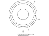
例えば、スプリング型クラッチディスクは、ハブとディスクとの間に装着されたコイルスプリングによってトルクを伝達すると共に、クラッチ接続時の緩衝および動力伝達系での振動防止作用を行う。このスプリング型クラッチディスクのコイルスプリングは、図7に示すように、クラッチディスク51の片面円周方向に沿って複数(図示例では6個)形成されたアーク状のスプリング溝52内に嵌合される。
For example, a spring type clutch disk transmits torque by a coil spring mounted between the hub and the disk, and performs a buffering action when the clutch is engaged and a vibration preventing action in a power transmission system. As shown in FIG. 7, the coil springs of this spring type clutch disk are fitted into arc-
スプリング溝52に嵌合される前の自由状態のコイルスプリング53は直線状をなしているため、この直線状のコイルスプリング53をそのままアーク状のスプリング溝52に嵌合すると、コイルスプリング53の外周面とスプリング溝52の内壁面との間の特にA点で強い摩擦抵抗が生じる。この摩擦抵抗はクラッチディスク51の径が小さい程、すなわち、アーク状のスプリング溝52の曲率半径が小さい程大きくなり、摩擦抵抗の大きさ如何によってはコイルスプリング53の外周面やクラッチディスク51のスプリング溝52の内壁面に傷が付いてコイルスプリング53の機能が低下する恐れがある。
Since the
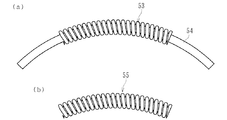
このため、コイルスプリング53を所謂アークスプリング化して摩擦抵抗を低減させることが知られている。従来のアークスプリング化する方法として、図8(a)に示すような製造方法が知られている。
For this reason, it is known to reduce the frictional resistance by making the
このアーク状コイルスプリングの製造方法は、直線状のコイルスプリング53のコイル内径側にアーク状の断面円形の芯金54を挿入することによってばねを湾曲した状態で、約350℃〜450℃で30分〜60分の低温焼鈍処理、所謂クリープテンパーを施すことにより、一定の曲率半径を有するアーク状のコイルスプリングを成形するというものである(例えば、特許文献1参照。)。
This arc-shaped coil spring manufacturing method is performed at a temperature of about 350 ° C. to 450 ° C. in a state where the spring is curved by inserting an arc-shaped
然しながら、この従来の製造方法では、直線状のコイルスプリング53のコイル内径側にアーク状の芯金54を1本毎挿入する必要があると共に、アーク状のコイルスプリングの曲率半径に対応して芯金54をそれぞれ準備する必要があるため、作業が煩雑となり作業効率が悪くなるだけでなく、芯金54の管理コストが嵩み、製造コスト高を招来するという問題があった。
However, in this conventional manufacturing method, it is necessary to insert one arc-shaped
さらに、図8(b)に示すように、このような方法により製造されたアーク状コイルスプリング55では、端部の曲率半径が他の部分に比べて大きくなり、全体として滑らかな湾曲ならない恐れがある。これでは、図7に示すように、クラッチディスク51のスプリング溝52の内壁面との間に過度な摩擦が発生し、安定したトルクを得ることが困難となる恐れがある。
Further, as shown in FIG. 8B, in the arc-
本発明は、各種の曲率半径に自在に対応できると共に、作業効率を向上させて低コスト化を図り、全体を均一な曲率半径からなるアーク状コイルスプリングの製造装置を提供することを目的とする。 An object of the present invention is to provide an apparatus for manufacturing an arc coil spring having a uniform curvature radius, which can freely cope with various curvature radii, improve work efficiency, reduce costs, and has a uniform curvature radius as a whole. .
係る目的を達成すべく、本発明のうち請求項1記載の発明は、直線状のコイルスプリングを湾曲した状態で保持し、所定の温度と時間で低温焼鈍処理することにより、一定の曲率半径を有するアーク状コイルスプリングを成形する製造装置において、前記アーク状コイルスプリングに対応する曲率半径に形成された内周面を有し、この内周面で前記直線状のコイルスプリングを跨架した状態で保持する半円筒状の固定受け金具と、この固定受け金具の内周面の曲率半径より小さい曲率半径からなる外周面を有し、前記コイルスプリングを押圧して湾曲させる円筒状の可動押圧金具と、この可動押圧金具を前記コイルスプリングに向けて押圧する駆動部と、前記固定受け金具に形成された貫通孔に進退自在に嵌挿され、前記コイルスプリングの両端面に当接して位置規制する一対の可動壁と、前記固定受け金具の外壁に沿って軸方向に延びる一対の固定板と、この固定板の長手方向に沿って螺合される複数の固定ボルトと、を備え、これら複数の固定ボルトのうち前記固定板の端部側の固定ボルトが前記固定受け金具に螺着されて前記固定板を位置決め固定すると共に、前記複数の固定ボルトのうち前記固定板の中央部の固定ボルトが前記可動壁に当接され、当該中央部の固定ボルトを前記固定受け金具側に押し込むことにより前記可動壁を前記固定受け金具の内周面から突出させ、前記コイルスプリングの端部をさらに湾曲させる。
In order to achieve such an object, the invention according to
このように、直線状のコイルスプリングを湾曲した状態で保持し、所定の温度と時間で低温焼鈍処理することにより、一定の曲率半径を有するアーク状コイルスプリングを成形する製造装置において、アーク状コイルスプリングに対応する曲率半径に形成された内周面を有し、この内周面で直線状のコイルスプリングを跨架した状態で保持する半円筒状の固定受け金具と、この固定受け金具の内周面の曲率半径より小さい曲率半径からなる外周面を有し、コイルスプリングを押圧して湾曲させる円筒状の可動押圧金具と、この可動押圧金具をコイルスプリングに向けて押圧する駆動部と、固定受け金具に形成された貫通孔に進退自在に嵌挿され、コイルスプリングの両端面に当接して位置規制する一対の可動壁と、固定受け金具の外壁に沿って軸方向に延びる一対の固定板と、この固定板の長手方向に沿って螺合される複数の固定ボルトと、を備え、これら複数の固定ボルトのうち固定板の端部側の固定ボルトが固定受け金具に螺着されて固定板を位置決め固定すると共に、複数の固定ボルトのうち固定板の中央部の固定ボルトが可動壁に当接され、当該中央部の固定ボルトを固定受け金具側に押し込むことにより可動壁を固定受け金具の内周面から突出させ、コイルスプリングの端部をさらに湾曲させるので、完成後のアーク状コイルスプリングの端部の曲率半径が他の部分に比べて大きくなるという特性を解消することができ、作業効率を向上させて低コスト化を図り、全体を均一な曲率半径からなるアーク状コイルスプリングを提供することができる。 Thus, in a manufacturing apparatus for forming an arc-shaped coil spring having a constant radius of curvature by holding a linear coil spring in a curved state and performing low-temperature annealing treatment at a predetermined temperature and time, an arc-shaped coil A semi-cylindrical fixed bracket having an inner circumferential surface formed with a radius of curvature corresponding to the spring and holding a linear coil spring straddling the inner circumferential surface; A cylindrical movable pressing metal fitting that has an outer circumferential surface with a smaller radius of curvature than the peripheral surface and that presses and curls the coil spring, a drive unit that presses the movable pressing metal piece toward the coil spring, and a fixed Along the outer wall of the fixed bracket and a pair of movable walls that are slidably inserted into the through holes formed in the bracket, abutting against both end faces of the coil springs to regulate the position A pair of fixing plates extending in the axial direction and a plurality of fixing bolts screwed along the longitudinal direction of the fixing plate, and the fixing bolts on the end side of the fixing plate among the plurality of fixing bolts are fixed The fixing plate is screwed to the receiving metal to position and fix the fixing plate. Among the plurality of fixing bolts, the fixing bolt at the center of the fixing plate is brought into contact with the movable wall, and the fixing bolt at the center is pushed into the fixing receiving metal. As a result, the movable wall protrudes from the inner peripheral surface of the fixed bracket, and the end of the coil spring is further curved, so that the radius of curvature of the end of the arc-shaped coil spring after completion is larger than that of other parts. The characteristics can be eliminated, the working efficiency can be improved, the cost can be reduced, and an arc-shaped coil spring having a uniform curvature radius can be provided.
好ましくは、請求項2に記載の発明のように、前記可動壁の一方の端面が前記固定受け金具の内周面の形状に沿った凹面に形成されると共に、他方の端面と前記固定ボルトの先端が凹凸嵌合されていれば、凹凸面からなる固定ボルトと可動壁の係合により調心機能が発揮され、固定ボルトを偏心された状態で押圧したとしても固定受け金具に対して可動壁がスムーズに進退することができる。
Preferably, as in the invention described in
また、請求項3に記載の発明のように、前記可動押圧金具が一対で構成され、前記固定受け金具の内周面の上方で、当該固定受け金具の軸線に沿って水平状に並設されていれば、ワークWの中央部への圧力の集中を緩和し、ワークW全体に滑らかな湾曲を形成することができる。 According to a third aspect of the present invention, the movable pressing metal fittings are configured as a pair, and are arranged in parallel horizontally along the axis of the fixed receiving metal fitting above the inner peripheral surface of the fixed receiving metal fitting. If so, the concentration of pressure on the center of the workpiece W can be alleviated, and a smooth curve can be formed on the entire workpiece W.
また、請求項4に記載の発明のように、前記可動押圧金具の両端面にブラケットが固定され、このブラケットの前記固定受け金具の端面側にピンが立設されると共に、前記固定受け金具の端面にロックアームが固定され、このロックアームの長手方向所定の位置に前記ピンに係止させるための凹所が形成され、当該ロックアームによって前記可動押圧金具と固定受け金具間の距離が保持されていれば、固定受け金具と可動押圧金具の距離を正確かつ安定して保持することができると共に、加工中の可動押圧金具の両端面の不均衡を解消することができ、精度良くワークを湾曲させることができる。 According to a fourth aspect of the present invention, brackets are fixed to both end faces of the movable pressing metal fitting, and pins are erected on the end face side of the fixed receiving metal fitting of the bracket. A lock arm is fixed to the end surface, and a recess for locking the pin is formed at a predetermined position in the longitudinal direction of the lock arm, and the distance between the movable pressing metal fitting and the fixed receiving metal fitting is maintained by the lock arm. If this is the case, the distance between the fixed receiving bracket and the movable pressing bracket can be held accurately and stably, and the imbalance between both end faces of the movable pressing bracket during processing can be eliminated, and the workpiece can be curved with high accuracy. Can be made.
本発明に係るアーク状コイルスプリングの製造装置は、直線状のコイルスプリングを湾曲した状態で保持し、所定の温度と時間で低温焼鈍処理することにより、一定の曲率半径を有するアーク状コイルスプリングを成形する製造装置において、前記アーク状コイルスプリングに対応する曲率半径に形成された内周面を有し、この内周面で前記直線状のコイルスプリングを跨架した状態で保持する半円筒状の固定受け金具と、この固定受け金具の内周面の曲率半径より小さい曲率半径からなる外周面を有し、前記コイルスプリングを押圧して湾曲させる円筒状の可動押圧金具と、この可動押圧金具を前記コイルスプリングに向けて押圧する駆動部と、前記固定受け金具に形成された貫通孔に進退自在に嵌挿され、前記コイルスプリングの両端面に当接して位置規制する一対の可動壁と、前記固定受け金具の外壁に沿って軸方向に延びる一対の固定板と、この固定板の長手方向に沿って螺合される複数の固定ボルトと、を備え、これら複数の固定ボルトのうち前記固定板の端部側の固定ボルトが前記固定受け金具に螺着されて前記固定板を位置決め固定すると共に、前記複数の固定ボルトのうち前記固定板の中央部の固定ボルトが前記可動壁に当接され、当該中央部の固定ボルトを前記固定受け金具側に押し込むことにより前記可動壁を前記固定受け金具の内周面から突出させ、前記コイルスプリングの端部をさらに湾曲させるようにしたので、完成後のアーク状コイルスプリングの端部の曲率半径が他の部分に比べて大きくなるという特性を解消することができ、作業効率を向上させて低コスト化を図り、全体を均一な曲率半径からなるアーク状コイルスプリングを提供することができる。 An apparatus for producing an arc coil spring according to the present invention holds an arc coil spring having a constant radius of curvature by holding the linear coil spring in a curved state and performing low temperature annealing treatment at a predetermined temperature and time. In the manufacturing apparatus for molding, a semi-cylindrical shape having an inner peripheral surface formed with a radius of curvature corresponding to the arc-shaped coil spring, and holding the linear coil spring in a state straddling the linear coil spring on the inner peripheral surface. A fixed receiving metal fitting, a cylindrical movable pressing metal fitting having an outer peripheral surface having a radius of curvature smaller than the curvature radius of the inner peripheral surface of the fixed receiving metal fitting, and pressing and curving the coil spring; and the movable pressing metal fitting A drive portion that presses against the coil spring, and a both-end surface of the coil spring that is slidably fitted into a through hole formed in the fixed bracket. A pair of movable walls that abut and regulate the position; a pair of fixed plates that extend in the axial direction along the outer wall of the fixed bracket; and a plurality of fixed bolts that are screwed along the longitudinal direction of the fixed plate; Among the plurality of fixing bolts, a fixing bolt on the end side of the fixing plate is screwed to the fixing bracket to position and fix the fixing plate, and among the plurality of fixing bolts, the fixing plate A fixed bolt at the center is brought into contact with the movable wall, and the movable wall is caused to protrude from the inner peripheral surface of the fixed bracket by pushing the fixed bolt at the center toward the fixed bracket. Since the end part is further curved, the characteristic that the radius of curvature of the end part of the arc coil spring after completion becomes larger than other parts can be eliminated, and the work efficiency is improved. Achieving cost reduction, it is possible to provide an arc-shaped coil springs made entirely of uniform radius of curvature.
直線状のコイルスプリングを湾曲した状態で保持し、所定の温度と時間で低温焼鈍処理することにより、一定の曲率半径を有するアーク状コイルスプリングを成形する製造装置において、前記アーク状コイルスプリングに対応する曲率半径に形成された内周面を有し、この内周面で前記直線状のコイルスプリングを跨架した状態で保持する半円筒状の固定受け金具と、この固定受け金具の内周面の曲率半径より小さい曲率半径からなる外周面を有し、前記固定受け金具の内周面の上方で、当該固定受け金具の軸線に沿って水平状に並設され、前記コイルスプリングに当接して湾曲させる円筒状の一対の可動押圧金具と、この可動押圧金具を前記コイルスプリングに向けて押圧する駆動部と、前記固定受け金具に形成された貫通孔に進退自在に嵌挿され、前記コイルスプリングの両端面に当接して位置規制する一対の可動壁と、前記固定受け金具の外壁に沿って軸方向に延びる一対の固定板と、この固定板の長手方向に沿って螺合される複数の固定ボルトと、を備え、これら複数の固定ボルトのうち前記固定板の端部側の固定ボルトが前記固定受け金具に螺着されて前記固定板を位置決め固定すると共に、前記複数の固定ボルトのうち前記固定板の中央部の固定ボルトが前記可動壁に当接され、当該中央部の固定ボルトを前記固定受け金具側に押し込むことにより前記可動壁を前記固定受け金具の内周面から突出させ、前記コイルスプリングの端部をさらに湾曲させる。 A linear coil spring is held in a curved state and is subjected to low temperature annealing treatment at a predetermined temperature and time, thereby producing an arc coil spring having a constant radius of curvature. A semi-cylindrical fixed receiving bracket that has an inner peripheral surface formed at a radius of curvature and that holds the linear coil spring across the inner peripheral surface, and an inner peripheral surface of the fixed receiving bracket An outer peripheral surface having a smaller radius of curvature than the inner peripheral surface of the fixed receiving bracket, and arranged horizontally along the axis of the fixed receiving bracket, in contact with the coil spring. A pair of cylindrical movable pressing fittings to be bent, a drive unit that presses the movable pressing fittings toward the coil spring, and a through-hole formed in the fixed receiving bracket so as to freely advance and retract. A pair of movable walls inserted and abutted against both end faces of the coil spring to regulate the position, a pair of fixed plates extending in the axial direction along the outer wall of the fixed bracket, and along the longitudinal direction of the fixed plate A plurality of fixing bolts to be screwed together, and among the plurality of fixing bolts, a fixing bolt on an end portion side of the fixing plate is screwed to the fixing receiving bracket to position and fix the fixing plate, and Among the plurality of fixing bolts, a fixing bolt at the center of the fixing plate is brought into contact with the movable wall, and the movable wall is moved into the inner side of the fixed receiving metal by pushing the fixing bolt at the center toward the fixed receiving metal. Projecting from the peripheral surface, the end of the coil spring is further curved.
以下、本発明の実施の形態を図面に基づいて詳細に説明する。
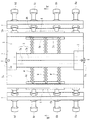
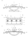
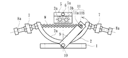
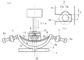
図1は、本発明に係るアーク状コイルスプリングの製造装置の一実施形態を示す分解斜視図、図2は、図1のアーク状コイルスプリングの製造装置の平面図、図3(a)は、図1のアーク状コイルスプリングの製造装置の正面図、(b)は、(a)の側面図、(c)は、図2のIII−III線に沿った横断面図、図4は、本発明に係る可動押圧金具の位置決め機構を示す正面図、図5(a)は、可動押圧金具のピンにロックアームが固定された状態を示す説明図、(b)は、(a)のロックアームの固定部を示す要部拡大図、図6(a)〜(d)は、本発明に係るアーク状コイルスプリングの製造工程を示す説明図である。
Hereinafter, embodiments of the present invention will be described in detail with reference to the drawings.
FIG. 1 is an exploded perspective view showing an embodiment of an arc-shaped coil spring manufacturing apparatus according to the present invention, FIG. 2 is a plan view of the arc-shaped coil spring manufacturing apparatus of FIG. 1, and FIG. 1 is a front view of the arc-shaped coil spring manufacturing apparatus of FIG. 1, (b) is a side view of (a), (c) is a cross-sectional view taken along line III-III of FIG. 2, and FIG. The front view which shows the positioning mechanism of the movable press metal fitting which concerns on invention, FIG. 5 (a) is explanatory drawing which shows the state by which the lock arm was fixed to the pin of a movable press metal fitting, (b) is the lock arm of (a). FIG. 6A to FIG. 6D are explanatory views showing the manufacturing process of the arc-shaped coil spring according to the present invention.
図1は、本発明に係るアーク状コイルスプリングの製造装置を示している。この製造装置は、基台1に固定され、直線状のコイルスプリング(以下、ワークという)Wを跨架した状態で保持する半円筒状の固定受け金具2と、駆動部となる図示しないエアシリンダー(またはフットプレス)の上下動に伴い、この固定受け金具2内に進退する圧力体3を主たる構成としている。
FIG. 1 shows an arc coil spring manufacturing apparatus according to the present invention. The manufacturing apparatus includes a semi-cylindrical fixed receiving
固定受け金具2は、断面が略半円形で、円筒のパイプを軸線方向に切断したような半円筒状に形成され、その底部が基台1に一体固定されている。固定受け金具2の内周面2aは、後述するアーク状コイルスプリングの曲率半径よりも小さい曲率半径になるように形成され、この内周面2aの上方にワークWが複数(ここでは、3個)配置される。また、固定受け金具2には、ワークWの両端面に当接して位置規制をする一対の可動壁4、4が進退自在に嵌挿されている。
The fixed
圧力体3は一対の円筒状の可動押圧金具3a、3bからなり、固定受け金具2の内周面2aの上方で、固定受け金具2の軸線に沿って水平状に並設され、一対のブラケット5、5にその両端面が固定されている。ブラケット5は、図3(b)に示すように、断面が逆L字状に形成され、固定受け金具2の端面側にそれぞれ突出した端面5aの略中央部にピン6が立設されている。
The
図2および図3(a)に示すように、固定受け金具2の外壁2bに沿って軸方向に延びる一対の固定板7、7が配設されている。この固定板7の長手方向には複数の固定ボルト8a〜8d(ここでは、4本)が螺合され、これら複数の固定ボルト8a〜8dのうち端部側の固定ボルト8a、8dは固定受け金具2に螺着され、固定板7を固定受け金具2に位置決め固定している。一方、複数の固定ボルト8a〜8dのうち残る中央部の固定ボルト8b、8cは後述する可動壁4、4に当接され、固定受け金具2に対して可動壁4、4を進退させる稼動部の働きをなす。
As shown in FIGS. 2 and 3A, a pair of fixing
可動壁4は固定受け金具2の軸線に沿って延びる板状に形成され、固定受け金具2に形成された矩形状の貫通孔2c内に進退自在に嵌合されている。可動壁4は、図3(c)に示すように、一方の端面4aは固定受け金具2の内周面2aの形状に沿った凹面に形成されると共に、他方の端面4bは蒲鉾状の凸面に形成されている。そして、この凸面からなる端面4bに嵌合するように、先端が円弧状の凹面に形成された固定ボルト8b、8cが当接されている。こうした凹凸面からなる固定ボルト8b、8cと可動壁4の係合により調心機能が発揮され、固定ボルト8b、8cを偏心された状態で押圧したとしても固定受け金具2に対して可動壁4、4がスムーズに進退することができる。なお、可動壁4の端面4bを逆に凹面にし、固定ボルト8b、8cを凸面に形成して、両者を凹凸嵌合させるようにしても良い。
The
図4に本発明に係る可動押圧金具3a、3bの位置決め機構を示す。固定受け金具2の両端面にはロックアーム9が枢軸10を介して揺動自在に取り付けられている。ロックアーム9にはブラケット5のピン6に係止させるための凹所11が形成されている。この凹所11は、図5(b)に拡大して示すように、ピン6の外径よりも僅かに大きく設定された矩形状の挿入溝11aと、この挿入溝11aの一方に円弧状の凹溝11bが形成されている。なお、凹溝11bはロックアーム9の長手方向の先端部側に形成されている。このように、可動押圧金具3a、3bの両端面にブラケット5が固定され、これらのブラケット5にロックアーム9が係止されるピン6がそれぞれ設けられているので、固定受け金具2と可動押圧金具3a、3bの距離を正確かつ安定して保持することができると共に、加工中の可動押圧金具3a、3bの両端面の不均衡を解消することができ、精度良くワークWを湾曲させることができる。
FIG. 4 shows a positioning mechanism for the movable
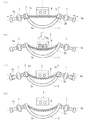
次に、図6(a)〜(d)を用いて、アーク状コイルスプリングの製造方法について説明する。
(a)に示すように、固定受け金具2の内周面2aの上方にワークWが整列された状態で跨架される。その後、(b)に示すように、圧力体3が図示しないエアシリンダーの下降に伴って下降され、ワークWを固定受け金具2の底部(矢印方向)に向け押圧して行く。そして、図5(a)に示すように、ワークWが所望の曲率半径に弾性変形した状態、すなわち、エアシリンダー12が下死点の状態で停止される。この時のエアシリンダー12のストローク量をL+αとする。その後、ロックアーム9を揺動させ、凹所11の挿入溝11aをブラケット5のピン6に係合させる。
Next, a method for manufacturing an arc coil spring will be described with reference to FIGS.
As shown to (a), the workpiece | work W is straddled on the upper direction of the internal
ここで、図5(b)に示すように、ピン6の先端部にはナット状の頭部6aが螺着され、加工中にロックアーム9が緩んだり、ピン6から外れたりしないよう、頭部6aがピン6に締め付けられ、ロックアーム9がガタなくピン6に固定される。なお、このピン6の外径と凹所11の凹溝11bとの距離(すきま)がαに設定されている。ここでは、加工性や作業性を考慮して、この距離αは2〜3mmに設定されている。
Here, as shown in FIG. 5 (b), a nut-
次に、エアシリンダー12を解放させて上死点まで上昇させると、ワークWの反発力によって圧力体3が僅かにαだけ上昇し、ピン6がロックアーム9の凹溝11bにすきまなく係止される。この状態が、図6(d)である。このように、ロックアーム9の凹所11に凹溝11bを設けてピン6を係止させるようにしたので、加工中に緩みが生じるのを防止し、量産時の加工効率を向上させることができる。
Next, when the
その後、固定ボルト8b、8cを固定受け金具2側(矢印にて示す)に押し込むことにより可動壁4を固定受け金具2の内周面2aから突出させ、ワークWの端部だけをさらに湾曲させる。このような一連の動作によって完成後のワークWの端部の曲率半径が他の部分に比べて大きくなるという特性を解消することができ、作業効率を向上させて低コスト化を図り、全体を均一な曲率半径からなるアーク状コイルスプリングを提供することができる。
Thereafter, the fixing
なお、固定ボルト8b、8cとワークWの端部に当接する可動壁4とは、ワークWの反発力によって常に所定の接触圧でもって当接しているため、固定ボルト8b、8cが如何なる位置にあっても可動壁4にガタが生ずることはなく、固定ボルト8b、8cの移動に追従して可動壁4を精度良く進退させることができる。
Note that the fixed
図6(c)に示す状態、すなわち、ワークWが位置決め固定された状態で、図示しないコンベアによって後述する熱処理工程に移行される。この熱処理終了後、ロックアーム9が揺動されてピン6から解放される。その後、図6(d)に示すように、図示しないエアシリンダーを上昇させると共に、固定ボルト8b、8cを元の位置に戻すことにより、可動壁4の端面4aが固定受け金具2の内周面2aに一致し、ワークWはこの圧力体3から解放されて容易に取り出すことができる。こうした製造装置を採用することにより、従来のように、アーク状のコイルスプリングの曲率半径に対応して芯金をそれぞれ準備する必要がなくなり、各種のアーク状コイルスプリングの曲率半径に自在に対応することができると共に、全体を均一な曲率半径からなるアーク状コイルスプリングを提供することができる。
In the state shown in FIG. 6C, that is, in a state in which the workpiece W is positioned and fixed, the process proceeds to a heat treatment step described later by a conveyor (not shown). After this heat treatment, the
また、本実施形態のように、圧力体3を一対の円筒状の可動押圧金具3a、3bで構成することにより、ワークWの中央部への圧力集中を緩和し、ワークW全体に滑らかな湾曲を形成することができる。
Further, as in the present embodiment, the
ここでは、圧力体3のストローク量によってワークWの曲率半径を管理するようにしたが、これ以外にも、例えば、図示しないが、圧力体を単一の円筒状の可動押圧金具で構成し、固定受け金具の内周面の曲率半径をワーク(完成後のアーク状コイルスプリング)の曲率半径と略同一に設定すると共に、可動押圧金具の曲率半径を固定受け金具の曲率半径よりも小さく設定し、ワークと固定受け金具の内周面とのすきまがなくなるまで圧力体を下降させてワークの曲率半径を管理するようにしても良い。なお、ここでいう「略同一」の略とは、例えば、設計の狙い値であって実質的に径差がない状態、すなわち、加工誤差等によって生じる径差は当然許容されるべきものである。
Here, the curvature radius of the workpiece W is managed by the stroke amount of the
次に、ワークWの熱処理工程等の後工程について説明する。図6(c)に示すように、ワークWの圧縮加工が終了した後、図示しないロックアームによって圧力体3と固定受け金具2が位置決め固定された状態で、雰囲気炉の中をコンベアによって移動される。雰囲気炉は全長2.0〜3.0mに設定され、25〜30分かけてワークWが加熱される。この時の温度条件は、ワークWの材質によって適宜設定されるが、例えば、ワークWの素材がばね用ピアノ線で形成されている場合は200〜300℃の範囲に、また、ステンレス線あるいはオイルテンパー線で形成されている場合は300〜420℃の範囲に設定される。すなわち、アーク状コイルスプリングの成型時と同様の温度条件に設定されるのが好ましい。
Next, post-processes such as a heat treatment process for the workpiece W will be described. As shown in FIG. 6 (c), after the compression processing of the workpiece W is completed, the
また、必要に応じて、アーク状コイルスプリングの成型の前、あるいは成型後にショットピーニング処理を実施することにより、耐へたり性と耐疲労性を向上させると共に、表面硬さを高めて耐摩耗性を向上させることができる。さらに、ショットピーニング処理の後、アーク状コイルスプリングのへたり防止のために、常温あるいは温間で圧縮セッチング等の処理を実施しても良い。 In addition, if necessary, shot peening can be performed before or after arc coil spring molding to improve sag resistance and fatigue resistance, and to increase surface hardness and wear resistance. Can be improved. Further, after the shot peening process, a process such as compression setting may be performed at room temperature or warm in order to prevent the arc-shaped coil spring from sagging.
以上、本発明の実施の形態について説明を行ったが、本発明はこうした実施の形態に何等限定されるものではなく、あくまで例示であって、本発明の要旨を逸脱しない範囲内において、さらに種々なる形態で実施し得ることは勿論のことであり、本発明の範囲は、特許請求の範囲の記載によって示され、さらに特許請求の範囲に記載の均等の意味、および範囲内のすべての変更を含む。 The embodiment of the present invention has been described above, but the present invention is not limited to such an embodiment, and is merely an example, and various modifications can be made without departing from the scope of the present invention. Of course, the scope of the present invention is indicated by the description of the scope of claims, and further, the equivalent meanings described in the scope of claims and all modifications within the scope of the scope of the present invention are included. Including.
本発明に係るアーク状コイルスプリングの製造装置は、ばね線材をコイリング成形により直線状のコイルスプリングに成形後、金型内に収容して圧縮荷重を加えた状態で円弧状に保持し、所定の低温焼鈍処理する製造装置に適用することができる。 The arc-shaped coil spring manufacturing apparatus according to the present invention, after forming a spring wire into a linear coil spring by coiling, holds it in a mold and holds it in a circular arc shape with a compressive load applied thereto. It can be applied to a manufacturing apparatus that performs low-temperature annealing.
1 基台
2 固定受け金具
2a 固定受け金具の内周面
2b 固定受け金具の外壁
2c 貫通孔
3 圧力体
3a、3b 可動押圧金具
4 可動壁
4a、4b 可動壁の端面
5 ブラケット
5a ブラケットの端面
6 ピン
6a ピンの頭部
7 固定板
8a〜8d 固定ボルト
9 ロックアーム
10 枢軸
11 凹所
11a 挿入溝
11b 凹溝
12 エアシリンダー
51 クラッチディスク
52 スプリング溝
53、55 コイルスプリング
54 芯金
L エアシリンダーのストローク量
W ワーク
α ピンの外径と凹所の凹溝との距離
DESCRIPTION OF
Claims (4)
前記アーク状コイルスプリングに対応する曲率半径に形成された内周面を有し、この内周面で前記直線状のコイルスプリングを跨架した状態で保持する半円筒状の固定受け金具と、
この固定受け金具の内周面の曲率半径より小さい曲率半径からなる外周面を有し、前記コイルスプリングを押圧して湾曲させる円筒状の可動押圧金具と、
この可動押圧金具を前記コイルスプリングに向けて押圧する駆動部と、
前記固定受け金具に形成された貫通孔に進退自在に嵌挿され、前記コイルスプリングの両端面に当接して位置規制する一対の可動壁と、
前記固定受け金具の外壁に沿って軸方向に延びる一対の固定板と、
この固定板の長手方向に沿って螺合される複数の固定ボルトと、を備え、
これら複数の固定ボルトのうち前記固定板の端部側の固定ボルトが前記固定受け金具に螺着されて前記固定板を位置決め固定すると共に、
前記複数の固定ボルトのうち前記固定板の中央部の固定ボルトが前記可動壁に当接され、当該中央部の固定ボルトを前記固定受け金具側に押し込むことにより前記可動壁を前記固定受け金具の内周面から突出させ、前記コイルスプリングの端部をさらに湾曲させることを特徴とするアーク状コイルスプリングの製造装置。 In a manufacturing apparatus for forming an arc-shaped coil spring having a constant radius of curvature by holding a linear coil spring in a curved state and performing low-temperature annealing treatment at a predetermined temperature and time,
A semi-cylindrical fixed bracket having an inner peripheral surface formed with a radius of curvature corresponding to the arc-shaped coil spring, and holding the linear coil spring in a state straddling the inner peripheral surface;
A cylindrical movable pressing metal fitting having an outer peripheral surface having a radius of curvature smaller than the radius of curvature of the inner peripheral surface of the fixed receiving metal fitting, and pressing and curving the coil spring;
A drive unit that presses the movable pressing fitting toward the coil spring;
A pair of movable walls that are inserted into a through-hole formed in the fixed receiving metal fitting so as to freely advance and retract, and abut against both end surfaces of the coil spring to regulate the position;
A pair of fixed plates extending in the axial direction along the outer wall of the fixed bracket;
A plurality of fixing bolts screwed along the longitudinal direction of the fixing plate,
Among the plurality of fixing bolts, a fixing bolt on the end portion side of the fixing plate is screwed to the fixing bracket to position and fix the fixing plate,
Among the plurality of fixing bolts, a fixing bolt at a center portion of the fixing plate is brought into contact with the movable wall, and the fixing wall at the center portion is pushed into the fixing bracket, thereby moving the movable wall to the fixed bracket. An apparatus for manufacturing an arc-shaped coil spring characterized by protruding from an inner peripheral surface and further bending the end of the coil spring.
Priority Applications (1)
| Application Number | Priority Date | Filing Date | Title |
|---|---|---|---|
| JP2013112630A JP5914413B2 (en) | 2013-05-29 | 2013-05-29 | Arc coil spring manufacturing equipment |
Applications Claiming Priority (1)
| Application Number | Priority Date | Filing Date | Title |
|---|---|---|---|
| JP2013112630A JP5914413B2 (en) | 2013-05-29 | 2013-05-29 | Arc coil spring manufacturing equipment |
Publications (2)
| Publication Number | Publication Date |
|---|---|
| JP2014231069A true JP2014231069A (en) | 2014-12-11 |
| JP5914413B2 JP5914413B2 (en) | 2016-05-11 |
Family
ID=52124797
Family Applications (1)
| Application Number | Title | Priority Date | Filing Date |
|---|---|---|---|
| JP2013112630A Active JP5914413B2 (en) | 2013-05-29 | 2013-05-29 | Arc coil spring manufacturing equipment |
Country Status (1)
| Country | Link |
|---|---|
| JP (1) | JP5914413B2 (en) |
Cited By (3)
| Publication number | Priority date | Publication date | Assignee | Title |
|---|---|---|---|---|
| CN105463161A (en) * | 2016-01-28 | 2016-04-06 | 佛山市昱纶机械有限公司 | Heat treatment device applied to bagged spring machine |
| CN112024790A (en) * | 2019-11-26 | 2020-12-04 | 苏州市新艺弹簧厂 | Bending device of bent pipe spring |
| US11248674B2 (en) | 2017-08-24 | 2022-02-15 | Ressorts Liberte Inc. | Coil spring and method of fabrication thereof |
Citations (4)
| Publication number | Priority date | Publication date | Assignee | Title |
|---|---|---|---|---|
| JPH0544339U (en) * | 1991-11-15 | 1993-06-15 | 中央発條株式会社 | Bending forming jig used to manufacture bent coil springs |
| JPH071065A (en) * | 1992-07-29 | 1995-01-06 | Fried Krupp Ag Hoesch Krupp | Method and device for manufacturing curved coil spring |
| JPH10237546A (en) * | 1997-02-26 | 1998-09-08 | Nhk Spring Co Ltd | Manufacture of coiled spring and apparatus therefor |
| JP2000129359A (en) * | 1998-10-19 | 2000-05-09 | Suncall Corp | Manufacture of arc-like spring for clutch disk |
-
2013
- 2013-05-29 JP JP2013112630A patent/JP5914413B2/en active Active
Patent Citations (4)
| Publication number | Priority date | Publication date | Assignee | Title |
|---|---|---|---|---|
| JPH0544339U (en) * | 1991-11-15 | 1993-06-15 | 中央発條株式会社 | Bending forming jig used to manufacture bent coil springs |
| JPH071065A (en) * | 1992-07-29 | 1995-01-06 | Fried Krupp Ag Hoesch Krupp | Method and device for manufacturing curved coil spring |
| JPH10237546A (en) * | 1997-02-26 | 1998-09-08 | Nhk Spring Co Ltd | Manufacture of coiled spring and apparatus therefor |
| JP2000129359A (en) * | 1998-10-19 | 2000-05-09 | Suncall Corp | Manufacture of arc-like spring for clutch disk |
Cited By (4)
| Publication number | Priority date | Publication date | Assignee | Title |
|---|---|---|---|---|
| CN105463161A (en) * | 2016-01-28 | 2016-04-06 | 佛山市昱纶机械有限公司 | Heat treatment device applied to bagged spring machine |
| US11248674B2 (en) | 2017-08-24 | 2022-02-15 | Ressorts Liberte Inc. | Coil spring and method of fabrication thereof |
| CN112024790A (en) * | 2019-11-26 | 2020-12-04 | 苏州市新艺弹簧厂 | Bending device of bent pipe spring |
| CN112024790B (en) * | 2019-11-26 | 2022-05-10 | 苏州市新艺弹簧厂 | Bending device of bent pipe spring |
Also Published As
| Publication number | Publication date |
|---|---|
| JP5914413B2 (en) | 2016-05-11 |
Similar Documents
| Publication | Publication Date | Title |
|---|---|---|
| JP5914413B2 (en) | Arc coil spring manufacturing equipment | |
| JP2016078234A (en) | Press plier | |
| KR102234943B1 (en) | Horizontal banding device | |
| JP2009536268A (en) | Method for manufacturing gears | |
| JP5855600B2 (en) | Arc coil spring manufacturing equipment | |
| JPH0966330A (en) | Method for thickening outer part of disk and method for forming disk member with drive part on outer periphery | |
| CA2467303C (en) | Rotary bending tool and method of manufacture | |
| JP5819659B2 (en) | Belleville spring and its manufacturing method | |
| JP6792292B2 (en) | Hydraulic deformation correction device equipped with a local pressurizing device and a local pressurizing device | |
| JP4923597B2 (en) | Method for forming cylindrical shaft product and mold | |
| EP1961503B1 (en) | Mandrel, set of mandrels, and hollow rack bar | |
| JP2017170461A (en) | Setting device | |
| JP2020089964A (en) | Method of manufacturing impeller blade of shot peening machine, and impeller blade | |
| JP2010260079A (en) | Bending apparatus, and brake shoe worked by the same | |
| JP6939489B2 (en) | Mold device | |
| JP6259210B2 (en) | Koma type ball screw | |
| JP5003184B2 (en) | Power transmission chain pin and manufacturing method thereof | |
| JP5906117B2 (en) | Dimple forming burnishing tool and workpiece machining method using the same | |
| WO2020070893A1 (en) | Machining tool and burnishing device | |
| JP2004124247A (en) | Heat treatment method and heat treatment apparatus for annular member | |
| JP2015116572A (en) | Metal mold | |
| JP2013151095A (en) | Slide core guide unit | |
| JP2009195987A (en) | Manufacturing method of cylindrical shaft | |
| JP2007203376A5 (en) | ||
| JP6502952B2 (en) | Tool for creating clinch type joints |
Legal Events
| Date | Code | Title | Description |
|---|---|---|---|
| A621 | Written request for application examination |
Free format text: JAPANESE INTERMEDIATE CODE: A621 Effective date: 20141219 |
|
| A977 | Report on retrieval |
Free format text: JAPANESE INTERMEDIATE CODE: A971007 Effective date: 20151125 |
|
| A131 | Notification of reasons for refusal |
Free format text: JAPANESE INTERMEDIATE CODE: A131 Effective date: 20151127 |
|
| A521 | Request for written amendment filed |
Free format text: JAPANESE INTERMEDIATE CODE: A523 Effective date: 20151224 |
|
| TRDD | Decision of grant or rejection written | ||
| A01 | Written decision to grant a patent or to grant a registration (utility model) |
Free format text: JAPANESE INTERMEDIATE CODE: A01 Effective date: 20160318 |
|
| A61 | First payment of annual fees (during grant procedure) |
Free format text: JAPANESE INTERMEDIATE CODE: A61 Effective date: 20160404 |
|
| R150 | Certificate of patent or registration of utility model |
Ref document number: 5914413 Country of ref document: JP Free format text: JAPANESE INTERMEDIATE CODE: R150 |
|
| R250 | Receipt of annual fees |
Free format text: JAPANESE INTERMEDIATE CODE: R250 |
|
| R250 | Receipt of annual fees |
Free format text: JAPANESE INTERMEDIATE CODE: R250 |
|
| R250 | Receipt of annual fees |
Free format text: JAPANESE INTERMEDIATE CODE: R250 |