JP2014226064A - Light emission control device, light emission control method, and program - Google Patents
Light emission control device, light emission control method, and program Download PDFInfo
- Publication number
- JP2014226064A JP2014226064A JP2013106798A JP2013106798A JP2014226064A JP 2014226064 A JP2014226064 A JP 2014226064A JP 2013106798 A JP2013106798 A JP 2013106798A JP 2013106798 A JP2013106798 A JP 2013106798A JP 2014226064 A JP2014226064 A JP 2014226064A
- Authority
- JP
- Japan
- Prior art keywords
- light emission
- light
- emission control
- control device
- cultivation area
- Prior art date
- Legal status (The legal status is an assumption and is not a legal conclusion. Google has not performed a legal analysis and makes no representation as to the accuracy of the status listed.)
- Pending
Links
Images
Landscapes
- Cultivation Of Plants (AREA)
Abstract
Description
本発明は、発光制御装置、発光制御方法、及びプログラムに関する。 The present invention relates to a light emission control device, a light emission control method, and a program.
近年は、人工的な光を植物に照射することにより、植物を栽培することが検討されている。例えば特許文献1には、栽培トレイを載置するトレイ載置棚の上方に照明具を配置し、植物の生長に合わせて栽培トレイ載置棚と照明具の間隔を調節することが記載されている。 In recent years, it has been studied to cultivate plants by irradiating them with artificial light. For example, Patent Document 1 describes that an illumination tool is arranged above a tray placement shelf on which a cultivation tray is placed, and the distance between the cultivation tray placement shelf and the illumination tool is adjusted according to the growth of the plant. Yes.
また特許文献2には、植物を水平方向に生長させ、かつ、その生長方向に合わせて光照射ユニットを伸縮自在にすることが記載されている。詳細には、光照射ユニットは円筒型の提灯形状の周壁を有している。周壁の内壁は反射面となっており、また、周壁の内側には環状発光体が設けられている。 Patent Document 2 describes that a plant is grown in the horizontal direction and the light irradiation unit can be expanded and contracted in accordance with the growth direction. Specifically, the light irradiation unit has a cylindrical lantern-shaped peripheral wall. The inner wall of the peripheral wall is a reflective surface, and an annular light emitter is provided inside the peripheral wall.
なお、特許文献3には、植物が栽培されているハウスの中に二酸化炭素を添加することが記載されている。特許文献3において、ハウス内の植物の光合成能力に応じてハウス内の照度、二酸化炭素濃度、及び温度が制御される、と記載されている。 Patent Document 3 describes that carbon dioxide is added to a house where plants are grown. Patent Document 3 describes that the illuminance, carbon dioxide concentration, and temperature in the house are controlled according to the photosynthetic ability of the plant in the house.
また特許文献4には、植物の栽培施設内の空気をファンで循環させることが記載されている。これにより、植物の育成のバラツキが少なくなる、と記載されている。 Patent Document 4 describes that air in a plant cultivation facility is circulated by a fan. Thereby, it is described that variation in plant growth is reduced.
植物に照射される光量が増大すると、光合成は活発になる。ただし、光量がある量以上になると、光合成速度は飽和する。このため、エネルギーの消費の無駄を省くために、植物に照射される光量を、光合成速度が飽和する光量付近に制御することが好ましい。しかし、この光量は植物の種類によって異なる。このため、植物の種類別に光量を設定する必要が出てくる。これに対応するためには、生長させる植物の種類が変わるたびに、ユーザが光量の最適値を発光部の制御装置に入力する必要がある。このため、ユーザの負荷が大きくなる。 Photosynthesis becomes more active as the amount of light applied to plants increases. However, when the amount of light exceeds a certain amount, the photosynthetic rate is saturated. For this reason, in order to eliminate wasteful consumption of energy, it is preferable to control the amount of light irradiated to the plant in the vicinity of the amount of light at which the photosynthetic rate is saturated. However, the amount of light varies depending on the type of plant. For this reason, it is necessary to set the amount of light for each type of plant. In order to cope with this, every time the type of plant to be grown changes, the user needs to input the optimum value of the light amount to the control device of the light emitting unit. For this reason, a user's load becomes large.
本発明が解決しようとする課題としては、植物に照射される光量を適切な値に制御することができ、かつ、ユーザに加わる負荷が大きくなることを抑制することが一例として挙げられる。 As an example of the problem to be solved by the present invention, it is possible to control the amount of light applied to the plant to an appropriate value and to suppress an increase in the load applied to the user.
請求項1に記載の発明は、植物が栽培される栽培エリアに向けて光を発光する発光部と、
前記栽培エリアの空気に含まれる検査対象成分の濃度を測定する濃度測定部と、
前記濃度測定部の測定結果の時間による微分値を用いて前記発光部の発光量を制御する制御部と、
を備える発光制御装置である。
The invention according to claim 1 is a light-emitting unit that emits light toward a cultivation area where plants are cultivated;
A concentration measuring unit for measuring the concentration of the component to be inspected contained in the air of the cultivation area;
A control unit for controlling the light emission amount of the light emitting unit using a differential value according to time of the measurement result of the concentration measuring unit;
Is a light emission control device.
請求項9に記載の発明は、発光部に、植物が栽培される栽培エリアに向けて光を発光させ、
前記栽培エリアの空気に含まれる検査対象成分の濃度を測定した結果の時間による微分値を用いて、前記発光部の発光量を制御する発光制御方法である。
Invention of Claim 9 makes a light emission part light-emit toward the cultivation area where a plant is grown,
It is the light emission control method which controls the light emission amount of the said light emission part using the differential value by the time of the result of having measured the density | concentration of the test target component contained in the air of the said cultivation area.
請求項10に記載の発明は、コンピュータを、発光部の制御部として機能させるためのプログラムであって、
前記発光部は、植物が栽培される栽培エリアに向けて光を発光し、
前記コンピュータに、
前記栽培エリアの空気に含まれる検査対象成分の濃度を測定した結果を取得し、前記結果の時間による微分値を算出する機能と、
前記微分値を用いて前記発光部の発光量を制御する機能と、
を実現させるプログラムである。
The invention according to
The light emitting unit emits light toward a cultivation area where plants are grown,
In the computer,
Obtaining the result of measuring the concentration of the test target component contained in the air of the cultivation area, the function of calculating the differential value by the time of the result,
A function of controlling the light emission amount of the light emitting unit using the differential value;
It is a program that realizes.
以下、本発明の実施の形態について、図面を用いて説明する。尚、すべての図面において、同様な構成要素には同様の符号を付し、適宜説明を省略する。 Hereinafter, embodiments of the present invention will be described with reference to the drawings. In all the drawings, the same reference numerals are given to the same components, and the description will be omitted as appropriate.
なお、以下に示す説明において、発光制御装置の各構成要素は、ハードウエア単位の構成ではなく、機能単位のブロックを示している。例えば制御部130は、任意のコンピュータのCPU、メモリ、メモリにロードされたプログラム、そのプログラムを格納するハードディスクなどの記憶メディア、ネットワーク接続用インタフェースを中心にハードウエアとソフトウエアの任意の組合せによって実現される。そして、その実現方法、装置には様々な変形例がある。
In the following description, each component of the light emission control device is not a hardware unit configuration but a functional unit block. For example, the
図1は、実施形態に係る発光制御装置の構成を説明するための図である。実施形態に係る発光制御装置は、発光部100、濃度測定部120、及び制御部130を備えている。発光部100は、植物が栽培される栽培エリア10に向けて光を発光する。濃度測定部120は、栽培エリア10の空気に含まれる検査対象成分の濃度を測定する。そして制御部130は、濃度測定部120の測定結果の時間による微分値を用いて発光部100の発光量を制御する。検査対象成分は、植物の光合成によって生成又は消費される成分、例えば二酸化炭素又は酸素である。以下、検査対象成分を二酸化炭素として説明を行う。
FIG. 1 is a diagram for explaining a configuration of a light emission control device according to the embodiment. The light emission control device according to the embodiment includes a
発光部100は、発光素子として、例えば有機EL(Organic Electroluminescence)素子、LED(Light Emitting Diode)、又は半導体レーザの少なくとも一つを有している。有機EL素子は、発光層を含む有機層を有している。有機層は、塗布法を用いて形成されていても良いし、蒸着法を用いて形成されていても良い。発光部が有する発光素子は、透光性を有していても良い。このような発光素子としては、例えば有機EL素子がある。発光素子が透光性を有していると、外光を栽培エリア10に入れることができる。LED、半導体レーザにおいてもガラス等の透光性のあるハウスで覆うことにより外光を栽培エリア10に入れることができる。
The
栽培エリア10内の植物が光合成を行うと、栽培エリア10における二酸化炭素の濃度は変化する。そして、栽培エリア10に照射される光量が増大すると、植物の光合成速度は増大するため、二酸化炭素の濃度の減少量は増大する。そして、光合成速度が飽和すると、二酸化炭素の濃度の減少量も飽和する。このため、濃度測定部120の測定結果の時間による微分値を用いると、植物の光合成速度が飽和しているか否かを判断することができる。従って、植物に照射される光量を適切な値に制御することができる。
When the plant in the
また、上記した原理は、植物の種類によらない。従って、ユーザは、制御部130に植物の種類を入力する必要はない。従って、ユーザに加わる負荷が大きくなることを抑制できる。
Moreover, the above principle does not depend on the kind of plant. Therefore, the user does not need to input the plant type to the
以下、制御部130が行う制御の一例について、詳しく説明する。
Hereinafter, an example of the control performed by the
図2(a)は、植物に照射される光量と植物の光合成速度の関係を示すグラフである。図2(b)は、光量と、二酸化炭素濃度の変化の時間による微分値との関係を示すグラフである。また図2(c)は、光量と、二酸化炭素濃度の変化の時間による2回微分値との関係を示すグラフである。図2(a)において、光合成速度は二酸化炭素の消費速度に置き換えることができる。 FIG. 2A is a graph showing the relationship between the amount of light applied to a plant and the photosynthesis rate of the plant. FIG. 2B is a graph showing the relationship between the amount of light and the differential value depending on the change time of the carbon dioxide concentration. FIG. 2C is a graph showing the relationship between the amount of light and the twice-differentiated value according to the change time of the carbon dioxide concentration. In FIG. 2 (a), the photosynthesis rate can be replaced by the consumption rate of carbon dioxide.
植物も呼吸をしているため、光量が少ない場合、光合成に伴う二酸化炭素の消費量が、呼吸に伴う二酸化炭素の排出量を下回る。この状態では、図2(a)に示すように、栽培エリア10内の二酸化炭素の濃度は上昇する。そして光量が増加するに伴い、光合成に伴う二酸化炭素の消費量が増加し、呼吸に伴う二酸化炭素の排出量を上回る。この変換点を、補償点とする。なお、図2(b)に示すグラフにおいて、補償点は、二酸化炭素の濃度の変化の時間による微分値が正から負に変わる点として示される。
Since plants also breathe, when the amount of light is small, the consumption of carbon dioxide associated with photosynthesis is less than the carbon dioxide emissions associated with respiration. In this state, as shown to Fig.2 (a), the density | concentration of the carbon dioxide in the
さらに光量が増加すると、光量の増加に伴って光合成に伴う二酸化炭素の消費量が増加する。これに伴い、二酸化炭素の濃度の減少速度は上昇する。そして、光合成の速度が飽和点に達すると、二酸化炭素の濃度の減少速度は一定値になる。なお、飽和点は、図2(b)に示すグラフにおいては、二酸化炭素の濃度の変化の時間による微分値が負かつ一定値になる点として示される。言い換えると、飽和点は、二酸化炭素の濃度の変化の時間による2回微分値が負から0になる点である。 As the amount of light further increases, the amount of carbon dioxide consumption associated with photosynthesis increases as the amount of light increases. Along with this, the rate of decrease in the concentration of carbon dioxide increases. When the rate of photosynthesis reaches the saturation point, the rate of decrease in the concentration of carbon dioxide becomes a constant value. In the graph shown in FIG. 2B, the saturation point is shown as a point at which the differential value according to the change time of the carbon dioxide concentration becomes negative and constant. In other words, the saturation point is a point at which the differential value twice with respect to the change in the concentration of carbon dioxide changes from negative to zero.
このため、光合成速度を最大にしたい場合、制御部130は、栽培エリア10における二酸化炭素の濃度の変化の時間による2回微分値が0になるまで、発光部100の光量を増大させればよい。
For this reason, when it is desired to maximize the photosynthetic rate, the
なお、栽培エリア10における二酸化炭素の濃度の変化の時間による2回微分値は、緩やかに0に近づく場合も考えられる。この場合、上記した2回微分値が0になるまで発光部100の光量を増大させると、コストパフォーマンスが低下する可能性が出てくる。このため、制御部130は、二酸化炭素の濃度の変化の時間による2回微分値が、0よりも小さく定められた基準値になったときに、発光部100の光量を固定しても良い。
In addition, the twice differential value by the time of the change of the density | concentration of the carbon dioxide in the
以下、図3,4を用いて、制御部130が行う制御の例を説明する。なお、これらの例において、濃度測定部120は、一定時間毎、例えば10分毎に栽培エリア10における二酸化炭素の濃度を測定し、測定結果を制御部130に出力している。
Hereinafter, an example of control performed by the
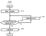
図3は、制御部130が行う制御の第1例を示すフローチャートである。本図に示すフローチャートは、栽培エリア10に照射される光量を植物の光合成速度の飽和点となる量に制御する方法を示している。
FIG. 3 is a flowchart illustrating a first example of control performed by the
まず制御部130は、発光部100を動作させる。これにより、栽培エリア10内の植物には光が照射される(ステップS10)。
First, the
そして制御部130は、濃度測定部120からの測定結果を用いて、栽培エリア10における二酸化炭素の濃度の時間による2回微分値を算出する。制御部130は、算出した2回微分値が基準値(例えば0またはその近くの負の値)になるまで(ステップS30:No)、発光部100からの光量を増大させる(ステップS40)。そして制御部130は、算出した2回微分値が基準値(例えば0またはその近くの負の値)に達する、又は超える(ステップS30:Yes)と、発光部100の発光量を固定する(ステップS50)。
And the
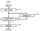
図4は、制御部130が行う制御の第2例を示すフローチャートである。本図に示すフローチャートは、栽培エリア10に照射される光量を植物の光合成速度の補償点となる量又はこれよりも少し強い程度に制御する方法を示している。このような制御は、例えばホワイトアスパラガスを栽培エリア10で生長させる場合に用いられる。
FIG. 4 is a flowchart illustrating a second example of control performed by the
まず制御部130は、発光部100を動作させる。これにより、栽培エリア10内の植物には光が照射される(ステップS10)。
First, the
そして制御部130は、濃度測定部120からの測定結果を用いて、栽培エリア10における二酸化炭素の濃度の時間による微分値を算出する。制御部130は、算出した微分値が正から0又は負になるまで(ステップS20:No)、発光部100からの光量を増大させる(ステップS22)。そして制御部130は、算出した微分値が正から0又は負になる(ステップS20:Yes)と、そのタイミングで発光部100の発光量を固定する(ステップS50)。
And the
以上、本実施形態によれば、制御部130は、濃度測定部120の測定結果の時間による微分値を用いて、発光部100の光量を制御している。これにより、植物に照射される光量を適切な値に制御することができる。そして、ユーザは、制御部130に植物の種類を入力する必要はない。従って、ユーザに加わる負荷が大きくなることを抑制できる。
As described above, according to the present embodiment, the
(実施例1)
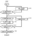
図5は、実施例1に係る制御部130が行う制御を示すフローチャートである。本実施例に係る発光制御装置の構成は、実施形態と同様である。そして本図に示す制御は、ステップS10とステップS30の間に、図4のステップS20,S22に示した処理を有している点を除いて、図3を用いて説明した制御と同様である。
Example 1
FIG. 5 is a flowchart illustrating the control performed by the
すなわち制御部130は、発光部100を発光させる(ステップS10)と、濃度測定部120からの測定結果を用いて、栽培エリア10における二酸化炭素の濃度の時間による微分値を算出する。そして制御部130は、算出した微分値が正から0又は負になるまで(ステップS20)、発光部100からの光量を増大させる(ステップS22)。
That is, if the
制御部130は、算出した微分値が正から0又は負になると(ステップS20:Yes)、ステップS30〜S50に示した処理を行う。
When the calculated differential value changes from positive to zero or negative (step S20: Yes), the
本実施例によっても、実施形態と同様の効果が得られる。また、制御部130は、算出した微分値が正から0又は負になるまで、2回微分を行わない。従って、制御部130が行う演算処理を少なくすることができる。
Also according to this example, the same effect as the embodiment can be obtained. Further, the
(実施例2)
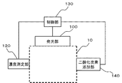
図6は、実施例2に係る発光制御装置の構成を示す図である。本実施例に係る発光制御装置は、二酸化炭素添加部140を備えている点を除いて、実施形態又は実施例1に係る発光制御装置と同様の構成である。二酸化炭素添加部140は、制御部130によって制御されており、栽培エリア10内の空気に二酸化炭素を添加する。
(Example 2)
FIG. 6 is a diagram illustrating a configuration of the light emission control apparatus according to the second embodiment. The light emission control device according to this example has the same configuration as that of the light emission control device according to the embodiment or Example 1 except that the carbon
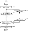
図7は、本実施例に係る制御部130が行う制御の一例を示すフローチャートである。本図は、実施例1をベースにした処理を示している。そして、ステップS20,S22までの処理は実施例1と同様であるため、説明を省略する。
FIG. 7 is a flowchart illustrating an example of control performed by the
制御部130は、算出した微分値が正から0又は負になると(ステップS20:Yes)、二酸化炭素添加部140を一定時間動作させ、栽培エリア10内の二酸化炭素濃度を増大させる(ステップS25)。その後、制御部130は、濃度測定部120による測定値を複数回、好ましくは3回以上受信し、二酸化炭素濃度を増大させた後の栽培エリア10内の二酸化炭素濃度の2回微分値を算出する。そして、二酸化炭素濃度が一定値になったことを確認した(ステップS27)後、算出した2回微分値が基準値(例えば0またはその近くの負の値)に達しているか否かを判断する(ステップS30)。2回微分値が基準値に達していない場合(ステップS30:No)、制御部130は、発光部100からの光量を増大させる処理(ステップS40)と、二酸化炭素濃度を増大させる処理(ステップS25)を行ってから、ステップS30に戻る。また、2回微分値が基準値に達していた場合(ステップS30:Yes)、制御部130は、発光部100の発光量を固定するとともに、現在の二酸化炭素濃度が維持されるように二酸化炭素添加部140を制御する(ステップS52)。
When the calculated differential value changes from positive to zero or negative (step S20: Yes), the
なお、図16に示すように、ステップS25において、二酸化炭素濃度を増大させるとともに、光量も増大させても良い。二酸化炭素濃度が高い場合、二酸化炭素濃度が低い場合と比べて光合成の最高速度は高くなる。このため、二酸化炭素濃度が高い場合の最適な光量は、二酸化炭素濃度が低い場合の最適な光量と比較して多くなる。本実施例では二酸化炭素濃度は高くなるため、最適な光量も多くなる。そしてステップS25において光量も増大させると、制御部連結部材130が最適な光量を設定するまでの時間は短くなる。
As shown in FIG. 16, in step S25, the carbon dioxide concentration may be increased and the amount of light may be increased. When the carbon dioxide concentration is high, the maximum rate of photosynthesis is higher than when the carbon dioxide concentration is low. For this reason, the optimal light amount when the carbon dioxide concentration is high is larger than the optimal light amount when the carbon dioxide concentration is low. In this embodiment, since the carbon dioxide concentration is high, the optimum amount of light is also increased. If the amount of light is also increased in step S25, the time until the control
本実施例によっても、実施形態又は実施例と同様の効果が得られる。また、制御部130は、二酸化炭素の濃度を上昇させてから、発光部100の発光量を制御している。従って、植物の生長速度をさらに速めることができる。
Also according to the present example, the same effect as the embodiment or the example can be obtained. Further, the
(実施例3)
図8は、実施例3に係る制御部130が行う制御を示すフローチャートである。本実施例において、制御部130は、外光(例えば太陽光)が栽培エリア10に十分照射されている場合は、発光部100を動作させない点を除いて、実施形態及び実施例1,2のいずれかと同様の構成である。本図は、実施例2と同様の場合を示している。
Example 3
FIG. 8 is a flowchart illustrating the control performed by the
具体的には、制御部130は、発光部100を動作させる前に、濃度測定部120からの測定結果を用いて、栽培エリア10における二酸化炭素の濃度の時間による微分値を算出する。そして制御部130は、算出した微分値が正の場合(ステップS20:No)、発光部100を動作させる(ステップS23)。その後、制御部130は、算出した微分値が正から0又は負になるまで(ステップS20:Yes)、発光部100からの光量を増大させる(ステップS23)。その後の処理(ステップS25〜S52)は、実施例2と同様である。
Specifically, before operating the
本実施例においても、実施形態及び実施例1,2のいずれかと同様の効果が得られる。また、制御部130は、外光が栽培エリア10に十分照射されている場合は、発光部100を動作させない。従って、消費エネルギーの無駄をさらに減らすことができる。
Also in the present example, the same effect as in any of the embodiment and Examples 1 and 2 can be obtained. Moreover, the
なお、本実施例において、図17に示すように、栽培エリア10に入り込む外光を、照度センサ104を用いて測定しても良い。この場合、図18に示すように、照度センサ104の測定値が基準値以下の場合(すなわち外光では光量が不十分な場合:ステップS5においてNo)に、制御部130は、発光部100を動作させ、その後、図8に示した処理を行っても良い。なお、照度センサ104の測定値が基準値以上の場合(すなわち外光では光量が十分な場合:ステップS5においてYes)、制御部130は、そのまま図8に示した処理を行う。
In this embodiment, as shown in FIG. 17, external light entering the
(実施例4)
図9は、実施例4に係る発光制御装置の構成を示す図である。本実施例に係る発光制御装置は、温度測定部150及びヒータ160を備えている点を除いて、実施形態及び実施例1〜3のいずれかと同様の構成である。本図は、実施例2と同様の場合を示している。
Example 4
FIG. 9 is a diagram illustrating the configuration of the light emission control apparatus according to the fourth embodiment. The light emission control device according to this example has the same configuration as that of any one of the embodiment and Examples 1 to 3 except that the
温度測定部150は、栽培エリア10内の空気の温度を測定する。ヒータ160は、栽培エリア10内の空気を昇温する。温度測定部150の測定結果は、制御部130に出力される。そして制御部130は、温度測定部150の測定結果に基づいて、ヒータ160を制御する。
The
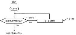
図10は、制御部130が行うヒータ160の制御の第1例を示すフローチャートである。本図に示す制御は、ステップS10の前(図8に示すフローではステップS20,S23の前)に行われる。具体的には、制御部130は、温度測定部150による測定結果が基準値以下の場合(ステップS100:No)、温度測定部150の測定結果が基準値以上になるまで、ヒータ160を動作させる(ステップS110)。すなわち制御部130は、ステップS10(又はステップS20,S23)以降の制御を行う前に、栽培エリア10内の温度を一定の温度(例えば20℃以上の値)以上にしておく。
FIG. 10 is a flowchart illustrating a first example of control of the
図11は、制御部130が行うヒータ160の制御の第2例を示すフローチャートである。本図に示す制御は、ステップS50(図8に示すフローではステップS52)の後に行われる。制御部130は、発光部100の発光強度を固定した(ステップS50)後、ヒータ160を動作させて、栽培エリア10内の気温を一定値上昇させる(ステップS200)。そして、その状態で、制御部130は、濃度測定部120による測定値を複数回、好ましくは3回以上受信し、気温の上昇させた後の栽培エリア10内の二酸化炭素濃度の2回微分値を算出する。そして、算出した2回微分値が基準値(例えば0またはその近くの負の値)に達しているか否かを判断する(ステップS210)。2回微分値が基準値に達していない場合(ステップS210:No)、制御部130は、再度ヒータ160を動作させて、栽培エリア10内の気温をさらに一定値上昇させ(ステップS200)、ステップS210に戻る。また、2回微分値が基準値に達していた場合(ステップS210:Yes)、制御部130は、現在の温度が維持されるようにヒータ160の動作を制御する(ステップS220)。
FIG. 11 is a flowchart illustrating a second example of the control of the
なお、制御部130は、図10に示す制御と図11に示す制御は、両方行っても良いし、いずれか一方のみ行っても良い。
In addition, the
本実施例によっても、実施形態及び実施例1〜3のいずれかと同様の効果が得られる。また、図11に示すように、発光部100の発光強度(及び栽培エリア10の内部の二酸化炭素の濃度)を固定した後、栽培エリア10の内部の気温の最適化を行っている。従って、栽培エリア10内の植物の生長をさらに促進することができる。
Also according to the present example, the same effects as those of the embodiment and any of Examples 1 to 3 can be obtained. Moreover, as shown in FIG. 11, after fixing the light emission intensity of the light emitting unit 100 (and the concentration of carbon dioxide inside the cultivation area 10), the temperature inside the
また、図10に示すように、発光部100の発光強度(及び栽培エリア10の内部の二酸化炭素の濃度)を固定する前に、栽培エリア10の内部の気温を一定値以上に上昇させている。従って、発光部100の発光強度や栽培エリア10の内部の二酸化炭素濃度の固定値は、適切な値になる。
Moreover, as shown in FIG. 10, before fixing the light emission intensity of the light emitting unit 100 (and the concentration of carbon dioxide inside the cultivation area 10), the temperature inside the
(実施例5)
図12は、実施例5に係る発光制御装置の構成を示す図である。本実施例において、発光制御装置は、栽培装置20の一部として構成されている。なお、本図では、発光制御装置は、発光部100及び制御部130を除いて図示を省略している。
(Example 5)
FIG. 12 is a diagram illustrating the configuration of the light emission control apparatus according to the fifth embodiment. In the present embodiment, the light emission control device is configured as a part of the
栽培装置20において、発光部100は、植物が栽培される栽培エリア10を側方及び上方から取り囲んでおり、かつ、内側に向けて光を出射する発光面を有している。また発光部100は、伸張部200を有している。伸張部200は、折りたたまれた状態から開くことによって垂直方向に伸張する。そして支持部220は、発光部100を上方から支持する。
In the
本図に示す例において、伸張部200は、複数の発光パネル102及び少なくとも一つの連結部202によって構成されている。隣り合う発光パネル102は、連結部202によって回転可能に連結されている。連結部202は、例えば蝶番と同様の構造を有している。そして、発光部100の断面形状が多角形(例えば5角形)である場合、連結部202は、多角形の各頂点に配置されている。そして連結部202のうち少なくとも2つは、栽培トレイ230の表面に配置されている。発光パネル102は、隣り合う連結部202の間の領域を塞ぐように、すなわち多角形の辺に沿って設けられている。すなわち連結部202は、発光パネル102を保持する保持部としても機能している。ただし発光パネル102は、多角形のうち栽培トレイ230の表面に沿った辺には設けられていない。
In the example shown in the figure, the
支持部220は、発光部100が有する連結部202の一つを上方から支持している。調整部210の動作及び発光部100の発光は、制御部130によって制御される。このため、容易に支持部220の高さを調節することができる。
The
本実施例によれば、発光部100は支持部220によって上方から支持されている。そして支持部220が上方に移動することにより、伸張部200は、水平方向に折りたたまれた状態から開く。このため、植物が小さいときには伸張部200の折りたたみ角度は小さい(開いていない)ため、発光パネル102のうち相対的に下に位置するほうは、上方に向けて光を出射する。このため、植物が小さいときには、植物の葉の裏側にも光を当てることができる。その結果、植物の育成スピードを上げることができる。また、植物の育成とともに、支持部220が上方に移動し、伸張部200は、水平方向に折りたたまれた状態から開くような構造となっている。このため、栽培装置20は、植物の育成状態に応じて光を当てることができる。
According to the present embodiment, the
また、発光パネル102が有機EL素子を有している場合、発光パネル102を半透明にすることができる。この場合、栽培装置20の外側から植物を観察することができる。
In addition, when the light-emitting
また、発光パネル102を連結部202から取り外し、その後新たな発光パネル102を取り付けることにより、発光パネル102のみを取り替えることができる。
Further, by removing the
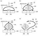
図13及び図14の各図は、連結部202の構成の詳細例を示す図である。まず、連結部202の一つは、フック212,214によって形成されている。フック212は、その連結部202に繋がっている発光パネル102の端部に形成されている。またフック214は、その連結部202に繋がっている発光パネル102の端部に形成されている。そして、図14(a)に示すように、フック212及びフック214が互いにかみ合うことにより、連結部202が形成される。
Each of FIGS. 13 and 14 is a diagram illustrating a detailed example of the configuration of the connecting
また、発光パネル102は可撓性基板を用いて形成されている。可撓性基板は、例えば樹脂材料で形成されている。
The light-emitting
本実施例では、図13(a)に示すように、植物が小さいときには、伸張部200を構成する発光パネル102のうち下側に位置する部分は、栽培トレイ230に対して平行に近い状態になっている。このため、植物の葉の裏側に光が照射される。
In this embodiment, as shown in FIG. 13A, when the plant is small, the lower portion of the
そして図13(b),(c)に示すように、植物が大きくなるにつれて、支持部220は上方に引き上げられる。これに伴い、伸張部200は、水平方向に折りたたまれた状態から開くことによって垂直方向に伸張する。この状態では、図14(b)及び図14(c)に示すように、フック212,214は互いにかみ合ったままである。
And as shown to FIG.13 (b), (c), the
そして図13(d)に示すように、植物が収穫可能な程度に大きくなると、それに合わせて支持部220も引き上げられる。すると、図14(d)に示すように、フック212とフック214からなる連結部202の角度は広がり、フック212とフック214は外れる。この状態において、伸張部200は栽培エリア10から取り外された状態になる。すなわち伸張部200は、栽培エリア10に対して着脱可能になっている。
And as shown in FIG.13 (d), if the plant becomes large to the extent that it can be harvested, the
本実施例によれば、実施形態及び実施例1〜4のいずれかと同様の効果を得ることができる。また、例えば外光(例えば太陽光)が十分強い場合は、伸張部200を栽培エリア10から取り外すことができる。この場合、十分に外光を栽培エリア10内に取り込むことができる。
According to the present example, the same effects as those of the embodiment and any of Examples 1 to 4 can be obtained. In addition, for example, when the external light (for example, sunlight) is sufficiently strong, the extending
また、植物の生長に合わせて伸張部200の形状を変えることもできる。また、連結部202の少なくとも一つは、フック212,214によって形成されている。そして植物が収穫可能な程度に大きくなり、それに合わせて支持部220が引き上げられると、フック212,214は外れる。このため、植物が収穫可能な程度に大きくなったことを容易に判断することができる。また植物の収穫を容易に行うことができる。
Further, the shape of the
なお、本実施例において、例えば図19に示すように、発光パネル102の外側に照度センサ104を取り付けても良い。
In this embodiment, as shown in FIG. 19, for example, an
(実施例6)
図15は、実施例6に係る発光制御装置の構成を示す図である。本実施例に係る発光制御装置は、以下の点を除いて実施例5に係る発光制御装置と同様の構成である。
(Example 6)
FIG. 15 is a diagram illustrating the configuration of the light emission control apparatus according to the sixth embodiment. The light emission control device according to this example has the same configuration as the light emission control device according to Example 5 except for the following points.
まず、発光制御装置は、ファン240,242を有している。ファン240,242は、栽培装置20の端部に配置されており、また互いに対向している。本図に示す例では、栽培装置20は筒状になっており、ファン240は栽培装置20の一端に、ファン242は栽培装置20の他端に、それぞれ設けられている。ファン240は、栽培装置20の内部の空気すなわち栽培エリア10の空気を排気しており、ファン242は栽培エリア10の内部に空気を送り込んでいる。そして濃度測定部120は、ファン240によって排気された空気の二酸化炭素濃度を測定しており、二酸化炭素添加部140は、ファン242によって送り込まれる空気に二酸化炭素を添加している。
First, the light emission control device has
また、本実施例では、ファン240によって排気された空気は、流路250を経由してファン242から栽培装置20の内部に戻される。そして、戻される際に、空気には必要に応じて二酸化炭素が添加される。
In this embodiment, the air exhausted by the
本実施例によっても、実施例5と同様の効果が得られる。また、ファン240によって排気された空気は、二酸化炭素濃度が測定された後、流路250を経由してファン242から栽培装置20の内部に戻される。そして、戻される際に、空気には必要に応じて二酸化炭素が添加される。従って、添加された二酸化炭素が無駄に排気されることを抑制できる。
According to the present embodiment, the same effect as that of the fifth embodiment can be obtained. The air exhausted by the
以上、図面を参照して実施形態及び実施例について述べたが、これらは本発明の例示であり、上記以外の様々な構成を採用することもできる。 As mentioned above, although embodiment and the Example were described with reference to drawings, these are illustrations of this invention and can also employ | adopt various structures other than the above.
10 栽培エリア
100 発光部
102 発光パネル
120 濃度測定部
130 制御部
140 二酸化炭素添加部
150 温度測定部
160 ヒータ
200 伸張部
240 ファン
242 ファン
250 流路
DESCRIPTION OF
Claims (10)
前記栽培エリアの空気に含まれる検査対象成分の濃度を測定する濃度測定部と、
前記濃度測定部の測定結果の時間による微分値を用いて前記発光部の発光量を制御する制御部と、
を備える発光制御装置。 A light emitting unit that emits light toward the cultivation area where the plant is grown,
A concentration measuring unit for measuring the concentration of the component to be inspected contained in the air of the cultivation area;
A control unit for controlling the light emission amount of the light emitting unit using a differential value according to time of the measurement result of the concentration measuring unit;
A light emission control device comprising:
前記検査対象成分は二酸化炭素であり、
前記制御部は、二酸化炭素の濃度の変化の時間による2回微分値が基準値になるまで、前記発光部の発光量を増大させる発光制御装置。 The light emission control device according to claim 1,
The component to be inspected is carbon dioxide,
The said control part is a light emission control apparatus which increases the light-emission quantity of the said light emission part until the 2nd derivative value by the time of the change of the density | concentration of a carbon dioxide becomes a reference value.
前記検査対象成分は二酸化炭素であり、
前記制御部は、前記発光部の発光量を増大させていき、かつ前記微分値が正から0または負となったタイミングで前記発光部の発光量の増大を停止する発光制御装置。 The light emission control device according to claim 1,
The component to be inspected is carbon dioxide,
The light emission control device, wherein the control unit increases the light emission amount of the light emitting unit, and stops increasing the light emission amount of the light emitting unit at a timing when the differential value becomes 0 or negative from positive.
前記発光部は、前記栽培エリアを側方及び上方から取り囲み、かつ折りたたまれた状態から開くことによって垂直方向に伸張する伸張部を備える発光制御装置。 In the light emission control device according to any one of claims 1 to 3,
The light emitting unit includes a stretching unit that surrounds the cultivation area from the side and from above and that extends in a vertical direction by opening from a folded state.
前記伸張部は、前記栽培エリアに対して着脱可能である発光制御装置。 The light emission control device according to claim 4,
The extension unit is a light emission control device that can be attached to and detached from the cultivation area.
前記検査対象成分は二酸化炭素であり、
前記栽培エリアからは空気が排出されており、かつ排出された空気に二酸化炭素が添加されて前記栽培エリアに戻されており、
前記濃度測定部は、前記排出された空気の二酸化炭素濃度を測定する発光制御装置。 In the light emission control apparatus as described in any one of Claims 1-5,
The component to be inspected is carbon dioxide,
Air is discharged from the cultivation area, and carbon dioxide is added to the discharged air and returned to the cultivation area,
The concentration measuring unit is a light emission control device that measures a carbon dioxide concentration of the discharged air.
前記発光部は、透光性の発光素子を有する発光制御装置。 In the light emission control device according to any one of claims 1 to 6,
The light emitting unit is a light emission control device having a light transmitting element.
前記発光素子は有機EL素子である発光制御装置。 In the light emission control device according to claim 7,
The light emission control device, wherein the light emitting element is an organic EL element.
前記栽培エリアの空気に含まれる検査対象成分の濃度を測定した結果の時間による微分値を用いて、前記発光部の発光量を制御する発光制御方法。 Let the light emitting part emit light toward the cultivation area where plants are grown,
The light emission control method which controls the light emission amount of the said light emission part using the differential value by the time of the result of having measured the density | concentration of the test object component contained in the air of the said cultivation area.
前記発光部は、植物が栽培される栽培エリアに向けて光を発光し、
前記コンピュータに、
前記栽培エリアの空気に含まれる検査対象成分の濃度を測定した結果を取得し、前記結果の時間による微分値を算出する機能と、
前記微分値を用いて前記発光部の発光量を制御する機能と、
を実現させるプログラム。 A program for causing a computer to function as a control unit of a light emitting unit,
The light emitting unit emits light toward a cultivation area where plants are grown,
In the computer,
Obtaining the result of measuring the concentration of the test target component contained in the air of the cultivation area, the function of calculating the differential value by the time of the result,
A function of controlling the light emission amount of the light emitting unit using the differential value;
A program that realizes
Priority Applications (1)
| Application Number | Priority Date | Filing Date | Title |
|---|---|---|---|
| JP2013106798A JP2014226064A (en) | 2013-05-21 | 2013-05-21 | Light emission control device, light emission control method, and program |
Applications Claiming Priority (1)
| Application Number | Priority Date | Filing Date | Title |
|---|---|---|---|
| JP2013106798A JP2014226064A (en) | 2013-05-21 | 2013-05-21 | Light emission control device, light emission control method, and program |
Publications (2)
| Publication Number | Publication Date |
|---|---|
| JP2014226064A true JP2014226064A (en) | 2014-12-08 |
| JP2014226064A5 JP2014226064A5 (en) | 2016-06-02 |
Family
ID=52126491
Family Applications (1)
| Application Number | Title | Priority Date | Filing Date |
|---|---|---|---|
| JP2013106798A Pending JP2014226064A (en) | 2013-05-21 | 2013-05-21 | Light emission control device, light emission control method, and program |
Country Status (1)
| Country | Link |
|---|---|
| JP (1) | JP2014226064A (en) |
Cited By (5)
| Publication number | Priority date | Publication date | Assignee | Title |
|---|---|---|---|---|
| WO2018056071A1 (en) * | 2016-09-23 | 2018-03-29 | ソニー株式会社 | Control device, control method, and control system |
| CN109310053A (en) * | 2016-06-16 | 2019-02-05 | 索尼公司 | Information processing equipment, information processing method and program |
| WO2019188848A1 (en) * | 2018-03-28 | 2019-10-03 | 国立大学法人愛媛大学 | Photosynthesis rate measurement system |
| JP2021145620A (en) * | 2020-03-19 | 2021-09-27 | 西日本電信電話株式会社 | Lighting control device for plant factory, lighting control method, and lighting control program |
| JP2021145618A (en) * | 2020-03-19 | 2021-09-27 | 西日本電信電話株式会社 | Lighting control device for plant factory, lighting control method, and lighting control program |
Citations (12)
| Publication number | Priority date | Publication date | Assignee | Title |
|---|---|---|---|---|
| JPS6094025A (en) * | 1983-10-28 | 1985-05-27 | 三菱電機株式会社 | Plant growing method |
| JPH05286655A (en) * | 1992-04-08 | 1993-11-02 | Toshiba Corp | Control device of self-mobile elevator |
| JPH06209654A (en) * | 1993-01-22 | 1994-08-02 | Ckd Corp | Supplemental lightening system |
| JPH08172913A (en) * | 1994-12-28 | 1996-07-09 | Tokyo Gas Co Ltd | Method for measuring rate of photosynthesis |
| JPH10268941A (en) * | 1997-03-24 | 1998-10-09 | Nikon Corp | Stage movement controller |
| JP2000188957A (en) * | 1998-10-21 | 2000-07-11 | Matsushita Electric Works Ltd | Method and apparatus for storing plant seedling |
| JP2001028946A (en) * | 1999-07-23 | 2001-02-06 | Matsushita Electric Works Ltd | Plant seedling-storage rack |
| JP2001251961A (en) * | 2000-03-10 | 2001-09-18 | Matsushita Electric Works Ltd | Method and apparatus for growing plant |
| JP2005080608A (en) * | 2003-09-10 | 2005-03-31 | Seiko Epson Corp | Plant growing apparatus |
| JP2006262852A (en) * | 2005-03-25 | 2006-10-05 | Sharp Corp | Culture system and method for controlling the same |
| JP2010511402A (en) * | 2006-12-07 | 2010-04-15 | コーニンクレッカ フィリップス エレクトロニクス エヌ ヴィ | Control equipment for greenhouse |
| JP2012100591A (en) * | 2010-11-10 | 2012-05-31 | Tsubakimoto Chain Co | Plant cultivation device |
-
2013
- 2013-05-21 JP JP2013106798A patent/JP2014226064A/en active Pending
Patent Citations (12)
| Publication number | Priority date | Publication date | Assignee | Title |
|---|---|---|---|---|
| JPS6094025A (en) * | 1983-10-28 | 1985-05-27 | 三菱電機株式会社 | Plant growing method |
| JPH05286655A (en) * | 1992-04-08 | 1993-11-02 | Toshiba Corp | Control device of self-mobile elevator |
| JPH06209654A (en) * | 1993-01-22 | 1994-08-02 | Ckd Corp | Supplemental lightening system |
| JPH08172913A (en) * | 1994-12-28 | 1996-07-09 | Tokyo Gas Co Ltd | Method for measuring rate of photosynthesis |
| JPH10268941A (en) * | 1997-03-24 | 1998-10-09 | Nikon Corp | Stage movement controller |
| JP2000188957A (en) * | 1998-10-21 | 2000-07-11 | Matsushita Electric Works Ltd | Method and apparatus for storing plant seedling |
| JP2001028946A (en) * | 1999-07-23 | 2001-02-06 | Matsushita Electric Works Ltd | Plant seedling-storage rack |
| JP2001251961A (en) * | 2000-03-10 | 2001-09-18 | Matsushita Electric Works Ltd | Method and apparatus for growing plant |
| JP2005080608A (en) * | 2003-09-10 | 2005-03-31 | Seiko Epson Corp | Plant growing apparatus |
| JP2006262852A (en) * | 2005-03-25 | 2006-10-05 | Sharp Corp | Culture system and method for controlling the same |
| JP2010511402A (en) * | 2006-12-07 | 2010-04-15 | コーニンクレッカ フィリップス エレクトロニクス エヌ ヴィ | Control equipment for greenhouse |
| JP2012100591A (en) * | 2010-11-10 | 2012-05-31 | Tsubakimoto Chain Co | Plant cultivation device |
Cited By (14)
| Publication number | Priority date | Publication date | Assignee | Title |
|---|---|---|---|---|
| CN109310053B (en) * | 2016-06-16 | 2022-06-07 | 索尼公司 | Information processing apparatus, information processing method, and computer program product |
| CN109310053A (en) * | 2016-06-16 | 2019-02-05 | 索尼公司 | Information processing equipment, information processing method and program |
| EP3504959A4 (en) * | 2016-09-23 | 2019-10-16 | Sony Corporation | Control device, control method, and control system |
| JPWO2018056071A1 (en) * | 2016-09-23 | 2019-07-04 | ソニー株式会社 | Control device, control method, and control system |
| WO2018056071A1 (en) * | 2016-09-23 | 2018-03-29 | ソニー株式会社 | Control device, control method, and control system |
| CN109714948A (en) * | 2016-09-23 | 2019-05-03 | 索尼公司 | Control equipment, control method and control system |
| JP7088017B2 (en) | 2016-09-23 | 2022-06-21 | ソニーグループ株式会社 | Control device, control method, and control system |
| US11656171B2 (en) | 2016-09-23 | 2023-05-23 | Sony Group Corporation | Control apparatus, control method, and control system |
| WO2019188848A1 (en) * | 2018-03-28 | 2019-10-03 | 国立大学法人愛媛大学 | Photosynthesis rate measurement system |
| JP2019170247A (en) * | 2018-03-28 | 2019-10-10 | 国立大学法人愛媛大学 | Photosynthesis speed measuring system |
| JP7181518B2 (en) | 2018-03-28 | 2022-12-01 | 国立大学法人愛媛大学 | Photosynthetic rate measurement system |
| JP2021145620A (en) * | 2020-03-19 | 2021-09-27 | 西日本電信電話株式会社 | Lighting control device for plant factory, lighting control method, and lighting control program |
| JP2021145618A (en) * | 2020-03-19 | 2021-09-27 | 西日本電信電話株式会社 | Lighting control device for plant factory, lighting control method, and lighting control program |
| JP7002586B2 (en) | 2020-03-19 | 2022-01-20 | 西日本電信電話株式会社 | Lighting control devices, lighting control methods, and lighting control programs for plant factories |
Similar Documents
| Publication | Publication Date | Title |
|---|---|---|
| JP2014226064A (en) | Light emission control device, light emission control method, and program | |
| CN107404850B (en) | Method and system for determining the growth status of a plant | |
| JP6530065B2 (en) | Hydroponic equipment | |
| US20150089867A1 (en) | Intelligent light sources to enhance plant response | |
| US20150289328A1 (en) | Lighting fixture with application controller | |
| US10349588B2 (en) | Hydroponic apparatus | |
| RU2009125900A (en) | REGULATORY DEVICE FOR GREENHOUSE | |
| US20170311553A1 (en) | Ultraviolet Plant Illumination System | |
| US20190261574A1 (en) | Horticultural system with closed-loop light control | |
| JP6327560B2 (en) | Hydroponic cultivation method and hydroponic cultivation apparatus | |
| JP6163000B2 (en) | Lighting control system | |
| JP2016000010A (en) | Carbon dioxide application system and carbon dioxide application method | |
| US10798879B1 (en) | Temporal, irradiance-controlled photoacclimation | |
| JPWO2018021142A1 (en) | Carbon dioxide application support device and carbon dioxide application support program | |
| JP2017127302A (en) | Plant growth accelerating apparatus, plant growth accelerating system using plant growth accelerating apparatus, and plant growth accelerating method | |
| US10271410B1 (en) | Method, device and computer program product for controlling lights | |
| WO2021022373A1 (en) | Plant enclosure with vertically distributed light sources | |
| JP2007274905A (en) | Lighting device | |
| KR20170080896A (en) | Horticulture light apparatus and a control method capable of controlling the amount of light needed by crops | |
| JP2014226064A5 (en) | ||
| JP5844458B2 (en) | Plant grower | |
| JP2021029158A (en) | Management system and management program | |
| WO2017002321A1 (en) | Plant growing device | |
| JP2015062409A (en) | Hydroponic apparatus and hydroponic method | |
| AU2018282535A1 (en) | System and method for utilizing waves in a grow pod |
Legal Events
| Date | Code | Title | Description |
|---|---|---|---|
| A521 | Request for written amendment filed |
Free format text: JAPANESE INTERMEDIATE CODE: A523 Effective date: 20160407 |
|
| A621 | Written request for application examination |
Free format text: JAPANESE INTERMEDIATE CODE: A621 Effective date: 20160407 |
|
| A521 | Request for written amendment filed |
Free format text: JAPANESE INTERMEDIATE CODE: A523 Effective date: 20160428 |
|
| A131 | Notification of reasons for refusal |
Free format text: JAPANESE INTERMEDIATE CODE: A131 Effective date: 20170110 |
|
| A521 | Request for written amendment filed |
Free format text: JAPANESE INTERMEDIATE CODE: A523 Effective date: 20170222 |
|
| A131 | Notification of reasons for refusal |
Free format text: JAPANESE INTERMEDIATE CODE: A131 Effective date: 20170808 |
|
| A02 | Decision of refusal |
Free format text: JAPANESE INTERMEDIATE CODE: A02 Effective date: 20180227 |


