JP2014222076A - Solenoid valve - Google Patents
Solenoid valve Download PDFInfo
- Publication number
- JP2014222076A JP2014222076A JP2013101104A JP2013101104A JP2014222076A JP 2014222076 A JP2014222076 A JP 2014222076A JP 2013101104 A JP2013101104 A JP 2013101104A JP 2013101104 A JP2013101104 A JP 2013101104A JP 2014222076 A JP2014222076 A JP 2014222076A
- Authority
- JP
- Japan
- Prior art keywords
- plunger
- valve
- electromagnetic valve
- contact
- guide hole
- Prior art date
- Legal status (The legal status is an assumption and is not a legal conclusion. Google has not performed a legal analysis and makes no representation as to the accuracy of the status listed.)
- Pending
Links
Images


Landscapes
- Valves And Accessory Devices For Braking Systems (AREA)
- Magnetically Actuated Valves (AREA)
Abstract
Description
本発明は、電磁弁、例えば、車両用液圧ブレーキ装置の液圧制御機器に組付けられて、ブレーキ液(作動液体)の液圧制御に用いられる電磁弁に関する。 The present invention relates to an electromagnetic valve, for example, an electromagnetic valve that is assembled in a hydraulic control device of a hydraulic brake device for a vehicle and used for hydraulic control of brake fluid (working fluid).
この種の電磁弁は、一般に、
作動液体の流入口および流出口と、これらを連通させる通路を有するとともに、前記通路中に設けられて一端部に弁座が形成されている弁孔を有し、かつ、前記弁孔に対して同軸的なガイド孔を有しているハウジング、
このハウジング内に収容され、前記弁座に対して着座・離座可能な弁体を一端部に有し、他端部の外周にて前記ガイド孔に接触して軸方向に移動可能なプランジャ、
前記ハウジング内に収容されて前記プランジャを前記弁座に向けて軸方向に付勢するスプリング、
前記ハウジングに組付けられて前記プランジャに対して前記スプリングの荷重(付勢力)に抗した吸引力(電磁力)を通電により発生させるソレノイド(電磁コイル)
を備えていて、例えば、下記特許文献1に示されている。
This type of solenoid valve is generally
An inflow port and an outflow port for the working liquid; a passage that communicates with the inflow port; a valve hole that is provided in the passage and has a valve seat formed at one end thereof; and A housing having a coaxial guide hole;
A plunger that is housed in the housing and has a valve body that can be seated and separated with respect to the valve seat at one end, and is movable in the axial direction in contact with the guide hole at the outer periphery of the other end;
A spring housed in the housing and biasing the plunger in the axial direction toward the valve seat;
A solenoid (electromagnetic coil) that is assembled to the housing and generates a suction force (electromagnetic force) against the load (biasing force) of the spring against the plunger by energization.
For example, it is shown by the following
上記特許文献1に記載されている電磁弁では、図14〜図16にて概略的に示したように、スプリング6にてプランジャ1に偏荷重(プランジャ1をハウジング2のガイド孔2aに押し付ける力)が得られるように構成して、液圧脈動(自励振動)の発生が抑制されるように構成されているが、スプリング6にて十分な偏荷重が得られない場合には、図14〜図16にてプランジャ1の外周とハウジング2のガイド孔2a間の隙間を誇張して示したように、弁体3が弁座4に着座しているとき、図14にて示したように、プランジャ1の一端部側(図14の下側)にて、弁体3と弁座4が第1の接触部位P1にて接触するとともに、プランジャ1の他端部側(図14の上側)にて、プランジャ1の他端部外周とガイド孔2aが第2の接触部位P2にて接触するようになる。また、ソレノイド5への通電に伴って、スプリング6の付勢力に抗して、図15にて示した状態を経て、図16にて示した状態に移行するようになる。なお、図15にて示した状態では、弁体3と弁座4が第1の接触部位P1にて接触しながら、弁体3が弁座4に対して摺動するとともに、プランジャ1の他端部外周とガイド孔2aが第2の接触部位P2にて接触しながら、プランジャ1がガイド孔2aに対して軸方向に摺動する。
In the electromagnetic valve described in the above-mentioned
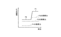
ところで、図16にて示した状態では、弁体3と弁座4の第1の接触部位P1における接触が解かれるとともに、プランジャ1の他端部外周とガイド孔2aが第2の接触部位P2にて接触し、プランジャ1の一端部外周とガイド孔2aが第3の接触部位P3にても接触しながら、プランジャ1がガイド孔2aに対して軸方向に摺動する。このときには、プランジャ1とガイド孔2a(ハウジング2間)間にて電磁力が発生していて、図17に示したように、プランジャ1に作用する軸方向の摩擦力Fが、プランジャ1の変位(軸方向変位)の増大に伴って、FoからF1へと急激に増大する。なお、図17の破線にて概略的に示した摩擦力(P1の摩擦力)は、第1の接触部位P1にて発生するものであり、図17の点線にて概略的に示した摩擦力(P2の摩擦力)は、第2の接触部位P2にて発生するものであり、図17の二点鎖線にて概略的に示した摩擦力(P3の摩擦力)は、第3の接触部位P3にて発生するものである。
By the way, in the state shown in FIG. 16, the contact between the
このため、上記特許文献1に記載されている電磁弁では、開弁の前後において、接触部位の変化(P1とP2からP2とP3に変化)に伴って、プランジャに作用する軸方向の摩擦力(摺動抵抗)が急激に変化し、これに伴って問題となる液圧脈動が発生するおそれがある。
For this reason, in the electromagnetic valve described in the above-mentioned
本発明は、上記した課題を解決すべくなされたものであり、本発明の電磁弁は、
作動液体の流入口および流出口と、これらを連通させる通路を有するとともに、前記通路中に設けられて一端部に弁座が形成されている弁孔を有し、かつ、前記弁孔に対して同軸的なガイド孔を有しているハウジング、
このハウジング内に収容され、前記弁座に対して着座・離座可能な弁体を一端部に有し、他端部の外周にて前記ガイド孔に接触して軸方向に移動可能なプランジャ、
前記ハウジング内に収容されて前記プランジャを前記弁座に向けて軸方向に付勢するスプリング、
前記ハウジングに組付けられて前記プランジャに対して前記スプリングの荷重に抗した吸引力を通電により発生させるソレノイド
を備えていて、
前記弁体が前記弁座に着座しているときに、前記弁体と前記弁座の接触部位と、前記プランジャの他端部外周と前記ガイド孔の接触部位との間において、前記ガイド孔に接触可能な接触部が前記プランジャに設けられている。
The present invention has been made to solve the above-described problems, and the solenoid valve of the present invention is
An inflow port and an outflow port for the working liquid; a passage that communicates with the inflow port; a valve hole that is provided in the passage and has a valve seat formed at one end thereof; and A housing having a coaxial guide hole;
A plunger that is housed in the housing and has a valve body that can be seated and separated with respect to the valve seat at one end, and is movable in the axial direction in contact with the guide hole at the outer periphery of the other end;
A spring housed in the housing and biasing the plunger in the axial direction toward the valve seat;
A solenoid that is assembled to the housing and generates a suction force against the load of the spring against the plunger by energization;
When the valve body is seated on the valve seat, the contact hole between the valve body and the valve seat, the outer periphery of the other end of the plunger and the contact hole of the guide hole, A contactable contact portion is provided on the plunger.
上記した本発明の実施に際して、前記接触部は、前記プランジャの一端部に径方向にて移動可能に組付けられたリング部材の外周部に設けられていることも可能である。この場合において、前記弁体は前記プランジャとは別部材で構成されていて、前記リング部材は前記弁体と前記プランジャによって軸方向にて挟持されていることも可能である。 In carrying out the above-described present invention, the contact portion may be provided on an outer peripheral portion of a ring member that is assembled to one end portion of the plunger so as to be movable in the radial direction. In this case, the valve body may be constituted by a member different from the plunger, and the ring member may be clamped in the axial direction by the valve body and the plunger.
本発明の電磁弁においては、前記弁体が前記弁座に着座しているときに、前記弁体と前記弁座の接触部位(第1の接触部位)と、前記プランジャの他端部外周と前記ガイド孔の接触部位(第2の接触部位)との間において、前記ガイド孔に接触可能な接触部が前記プランジャに設けられている。このため、当該電磁弁の開弁時において、弁体が弁座から開弁方向に移動して弁座との接触を解かれるまでの間において、プランジャに設けた接触部がガイド孔に接触して、第3の接触部位にてプランジャに軸方向の摩擦力(摺動抵抗)が作用する。したがって、本発明の電磁弁では、開弁の前後において、プランジャに作用する軸方向の摩擦力(摺動抵抗)が大きく変化することを抑制することが可能であり、同変化に伴う液圧脈動の発生を抑制することが可能である。 In the electromagnetic valve according to the present invention, when the valve body is seated on the valve seat, a contact portion (first contact portion) between the valve body and the valve seat, and an outer periphery of the other end portion of the plunger A contact portion that can contact the guide hole is provided on the plunger between the contact portion (second contact portion) of the guide hole. For this reason, when the solenoid valve is opened, the contact portion provided on the plunger contacts the guide hole until the valve element moves from the valve seat in the valve opening direction and is released from contact with the valve seat. Thus, an axial frictional force (sliding resistance) acts on the plunger at the third contact site. Therefore, in the solenoid valve of the present invention, it is possible to suppress a large change in the axial frictional force (sliding resistance) acting on the plunger before and after opening the valve. Can be suppressed.
上記した本発明の実施に際して、前記リング部材は磁性体の材料を含んで形成されていることも可能である。この場合には、ソレノイドの通電時に、リング部材の外周部(接触部)とガイド孔が電磁力により強く接触し、大きな摩擦力が効果的に得られる。この場合において、前記ガイド孔と接触する前記リング部材の外表面は非磁性体で構成されていることも可能である。この場合には、リング部材の外表面を構成する非磁性体の材質もしくは同外表面の加工法(外表面を非磁性とするための加工法)を適宜に選ぶことにより、リング部材の外周部(接触部)とガイド孔間にて得られる摩擦力をコントロールすることが可能である。 In carrying out the above-described present invention, the ring member may be formed to include a magnetic material. In this case, when the solenoid is energized, the outer peripheral portion (contact portion) of the ring member and the guide hole come into strong contact with each other by electromagnetic force, and a large frictional force is effectively obtained. In this case, the outer surface of the ring member in contact with the guide hole may be made of a nonmagnetic material. In this case, by appropriately selecting the material of the non-magnetic material constituting the outer surface of the ring member or the processing method of the outer surface (processing method for making the outer surface non-magnetic), the outer periphery of the ring member It is possible to control the frictional force obtained between the (contact portion) and the guide hole.
また、上記した本発明の実施に際して、前記弁体と前記プランジャが別部材で構成されている場合、前記リング部材の内周部には軸方向にて作動液体の流通を可能とする通路が設けられ、前記プランジャには前記通路に連通可能で作動液体の流通を軸方向にて可能な貫通孔が設けられていて、前記通路と前記貫通孔の回転位相を固定可能な固定部が設けられていることも可能である。この場合において、前記固定部は、前記弁体および前記プランジャとは別部材に設けられていることも可能であり、前記弁体または前記プランジャに一体的に設けられていることも可能である。 Further, when the above-described present invention is implemented, when the valve body and the plunger are composed of separate members, a passage that allows the working liquid to flow in the axial direction is provided in the inner peripheral portion of the ring member. The plunger is provided with a through-hole that can communicate with the passage and allows the working liquid to flow in the axial direction, and is provided with a fixing portion that can fix the rotational phase of the passage and the through-hole. It is also possible. In this case, the fixing portion can be provided as a separate member from the valve body and the plunger, or can be provided integrally with the valve body or the plunger.
この場合(前記通路と前記貫通孔の回転位相を固定可能な固定部が設けられている場合)には、前記通路と前記貫通孔の回転位相を合わせた状態にて、プランジャにリング部材を組付けることが可能である。また、この場合には、プランジャに対するリング部材の回転を固定部によって抑制することができて、前記通路と前記貫通孔の回転位相ズレを抑制することが可能である。 In this case (when a fixing portion capable of fixing the rotational phase of the passage and the through hole is provided), a ring member is assembled to the plunger in a state where the rotational phases of the passage and the through hole are matched. It is possible to attach. Further, in this case, the rotation of the ring member relative to the plunger can be suppressed by the fixing portion, and the rotational phase shift between the passage and the through hole can be suppressed.
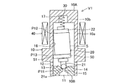
以下に、本発明の実施形態を図面に基づいて説明する。図1〜図4は本発明に係る電磁弁の第1実施形態を概略的に示していて、この実施形態の電磁弁V1は、例えば、車両用液圧ブレーキ装置の液圧制御機器に組付けられて、ブレーキ液(作動液体)の液圧制御に用いられる常閉型電磁弁である。また、この電磁弁V1では、ハウジング10にプランジャ20、スプリング30、ソレノイド40等が組付けられている。
Embodiments of the present invention will be described below with reference to the drawings. 1 to 4 schematically show a first embodiment of a solenoid valve according to the present invention. The solenoid valve V1 of this embodiment is assembled to a hydraulic control device of a hydraulic brake device for a vehicle, for example. And a normally closed solenoid valve used for controlling the hydraulic pressure of the brake fluid (working fluid). Further, in the electromagnetic valve V1, a
ハウジング10は、プランジャ20、スプリング30等を内部に収容していて、ブレーキ液の流入口11および流出口12と、これらを連通させる通路13を有するとともに、通路13中に設けられて一端部(上端部)に弁座14が形成されている弁孔15を有している。また、ハウジング10は、ガイド部10aと固定コア部10bを備えていて、ガイド部10aには弁孔15に対して同軸的なガイド孔16が設けられ、固定コア部10bにはスプリング30の一部を収容するスプリング収容穴17が設けられている。
The
なお、ハウジング10は、流出口12とガイド孔16とスプリング収容穴17を設けた第1ハウジング10Aと、流入口11と弁座14と弁孔15を設けた第2ハウジング10Bを備えている。第1ハウジング10Aでは、ガイド孔16の上端部を形成する部位(この部位は非磁性とされている)を除いて磁性体からなり、プランジャ20とにより磁路を形成するように構成されている。
The
プランジャ20は、非磁性体からなる弁体21と、円柱状で磁性体からなる可動コア22を備えている。弁体21は、弁座14に対して着座・離座可能な弁部21aを有している。また、弁体21は、可動コア22の図1下端部軸心(一端部の軸心)に設けた取付孔(図1〜図3では図示省略)に嵌合固定されていて、可動コア22と一体的に移動可能とされている。可動コア22は、外周(上端部を除いて非磁性で薄肉のスリーブS(図7参照)が設けられている)にてハウジング10のガイド孔16に接触して軸方向にて移動可能(摺動可能)に組付けられている。この可動コア22(プランジャ20)の外周とハウジング10(ガイド部10a)間には、所望の隙間(図1〜図3では誇張して示されている)が設定されていて、プランジャ20のハウジング10に対する軸方向の摺動性が確保されているとともに、ブレーキ液の流動性(流通性)が確保されている。
The
スプリング30は、ハウジング10内に収容された状態にて、ハウジング10とプランジャ20間に介装されていて、プランジャ20を弁座14に向けて軸方向に付勢している。ソレノイド40は、ハウジング10外に周知のように配設されている。このソレノイド40では、その通電時に、ハウジング10のガイド部10aおよび固定コア部10bとプランジャ20の可動コア22等とによって磁路(プランジャ20に対してスプリング30の荷重に抗した吸引力(電磁力)を、ソレノイド40への通電により発生させるもの)を形成するように構成されている。
The
ところで、この実施形態では、プランジャ20における可動コア22の下端部(弁座側端部)にリング部材50が組付けられている。リング部材50は、プランジャ20に対して径方向に移動可能に組付けられていて、外周部(接触部)51にてガイド孔16に接触している。なお、この実施形態では、図1の状態においても外周部(接触部)51とガイド孔16が接触するように設定されている(例えば、リング部材50の外径がガイド孔16の内径以上に設定されている)が、図1の状態にて外周部(接触部)51とガイド孔16が離間するように設定することも可能である。
By the way, in this embodiment, the
リング部材50の外周部(接触部)51は、弁体21の弁部21aが弁座14に着座しているときに、弁体21の弁部21aと弁座14の接触部位(第1の接触部位)P11と、可動コア22の上端部外周とガイド孔16の接触部位(第2の接触部位)P12との間となる部位(第3の接触部位)P13にて、ガイド孔16に接触している。これにより、リング部材50の外周部(接触部)51は、図1の状態から図3の状態に移行するときに、ガイド孔16に接触している。なお、図1の状態から図2の状態を経て図3の状態に移行するときには、リング部材50がプランジャ20に対して径方向にて相対的に移動する。
The outer peripheral portion (contact portion) 51 of the
このため、当該電磁弁V1の開弁時には、弁体21の弁部21aが弁座14から開弁方向に移動して弁座14との接触を解かれるまでの間(図1の状態から図3の状態に移行する間)の全領域において、プランジャ20に設けたリング部材50の外周部(接触部)51がガイド孔16に接触して、第3の接触部位P13にてプランジャ20に軸方向の摩擦力(摺動抵抗)が作用する。
Therefore, when the electromagnetic valve V1 is opened, the
したがって、この電磁弁V1では、開弁の前後において、プランジャ20に作用する軸方向の摩擦力(摺動抵抗)Fが図4の実線のようにF2からF1に変化する(開弁の後期において、第1の接触部位P11にて得られる摩擦力(第2の接触部位P12にて得られる摩擦力(P12の摩擦力)や第3の接触部位P13にて得られる摩擦力(P13の摩擦力)に比して小さい摩擦力(P11の摩擦力))が消失する)こととなる。このため、開弁の前後において、プランジャ20に作用する軸方向の摩擦力(摺動抵抗)が大きく変化することを抑制することが可能であり、同変化に伴う液圧脈動の発生を抑制することが可能である。
Therefore, in this electromagnetic valve V1, the axial frictional force (sliding resistance) F acting on the
かかる作用効果は、図4に示した摩擦力と図17に示した摩擦力の各変化量を比較することでも明らかである。なお、図4の破線にて概略的に示した摩擦力(P11の摩擦力)は、第1の接触部位P11にて発生するものであり、図4の点線にて概略的に示した摩擦力(P12の摩擦力)は、第2の接触部位P12にて発生するものであり、図4の二点鎖線にて概略的に示した摩擦力(P13の摩擦力)は、第3の接触部位P13にて発生するものである。 Such an effect is also apparent by comparing the amount of change in the frictional force shown in FIG. 4 and the frictional force shown in FIG. Note that the frictional force schematically indicated by the broken line in FIG. 4 (the frictional force P11) is generated at the first contact site P11, and is indicated schematically by the dotted line in FIG. (Friction force of P12) is generated at the second contact site P12, and the frictional force schematically shown by the two-dot chain line in FIG. 4 (friction force of P13) is the third contact site. This occurs at P13.
上記した第1実施形態の電磁弁V1では、弁体21の弁部21aが弁座14に着座している図1の状態(ソレノイド40への通電時でも非通電時でも同じ)において、プランジャ20に設けたリング部材50の外周部(接触部)51がガイド孔16に接触するように設定して実施したが、図5および図6に概略的に示した第2実施形態の電磁弁V2のように構成して実施することも可能である。
In the electromagnetic valve V1 of the first embodiment described above, the
この第2実施形態の電磁弁V2では、弁体21の弁部21aが弁座14に着座している状態で、ソレノイド40が非通電状態である場合、図5に示したように、プランジャ20に設けたリング部材50がガイド孔16と可動コア22から離間し、また、ソレノイド40が通電状態である場合、図6に示したように、リング部材50がガイド孔16と可動コア22に接触するように設定して実施することも可能である。
In the electromagnetic valve V2 of the second embodiment, when the
ソレノイド40の通電時に、リング部材50がガイド孔16と可動コア22に接触するのは、通電に伴って発生する電磁力によりリング部材50が軸方向および径方向に移動して、リング部材50と可動コア22間の軸方向隙間およびリング部材50とガイド孔16間に径方向隙間が無くなるからである。これにより、この第2実施形態では、ソレノイド40の通電時、リング部材50の外周部(接触部)51とガイド孔16が電磁力により強く接触し、大きな摩擦力が効果的に得られる。
When the
この第2実施形態の実施に際しては、リング部材50を磁性体で構成する必要があるが、リング部材50の外周部(接触部)51とガイド孔16が接触する部位での摩擦力を小さく設定したい場合には、図7に示したように、外周部(接触部)51のガイド孔16と接触する外表面を薄肉の非磁性層(例えば、SUS製または非磁性樹脂製のスリーブ)として実施することも可能である。上記非磁性層は、フッ素コート等の非磁性膜塗布によって形成することも可能である。なお、プランジャ20と可動コア22間での摩擦力を小さく設定したい場合には、リング部材50の図7上面に非磁性層を設ければよい。
In carrying out the second embodiment, the
外周部(接触部)51のガイド孔16と接触する外表面を薄肉の非磁性層として構成した実施形態(図7の実施形態)では、非磁性層の材質もしくは同非磁性層の加工法(外表面を非磁性とするための加工法)を適宜に選ぶことにより、リング部材50の外周部(接触部)51とガイド孔16間にて得られる摩擦力をコントロールすることが可能である。
In the embodiment (the embodiment of FIG. 7) in which the outer surface that contacts the
上記した各実施形態においては、作動液体の流通を軸方向にて可能な貫通孔がプランジャ20に設けられていない実施形態について説明したが、図8〜図10に示した第3実施形態の電磁弁V3のように、作動液体の流通を軸方向にて可能な貫通孔22aがプランジャ20に設けられているような場合には、リング部材50の内周部に、軸方向にて作動液体の流通を可能とする通路52を設けるとともに、貫通孔22aと通路52の回転位相を固定するための位置決めリング60を設けて実施すればよい。位置決めリング60は、リング部材50の内周部に設けた係止孔53に係合する固定突起(固定部)61を有していて、弁体21の軸部21bに嵌合されており、プランジャ20の弁体21と可動コア22間にて回転不能に挟持されている。
In each of the above-described embodiments, the embodiment has been described in which the
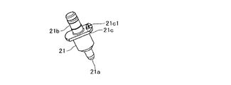
上記した第3実施形態の電磁弁V3では、貫通孔22aと通路52の回転位相を固定するために、位置決めリング60に固定突起61を設けて実施したが、図11〜図13に示した第3実施形態の変形実施形態のように、弁体21自体のフランジ部21cに固定爪21c1を設けて実施することも可能である。この変形実施形態では、第3実施形態の場合に必要な位置決めリング60が不要でありシンプルに構成することが可能である。
In the electromagnetic valve V3 of the third embodiment described above, the fixing
上記した第3実施形態およびその変形実施形態(貫通孔22aと通路52の回転位相を固定可能な固定部(固定突起61または固定爪21c1)が設けられている実施形態)の電磁弁V3では、貫通孔22aと通路52の回転位相を合わせた状態にて、プランジャ20にリング部材50を組付けることが可能である。また、この場合には、プランジャ20に対するリング部材50の回転を固定部(固定突起61または固定爪21c1)によって抑制することができて、貫通孔22aと通路52の回転位相ズレを抑制することが可能である。
In the electromagnetic valve V3 of the third embodiment described above and its modified embodiment (embodiment provided with a fixing portion (fixing
上記した各実施形態においては、プランジャ20の弁体21と可動コア22(プランジャの本体部)が別部材で構成されているが、本発明の実施に際して、プランジャ20の弁体21と可動コア22(プランジャの本体部)は一部材で構成して実施することも可能である。また、上記した各実施形態においては、プランジャ20に設けられてガイド孔16に接触可能な接触部(リング部材50の外周部51)が、プランジャ20の一端部に径方向にて移動可能に組付けられたリング部材50に設けられているが、本発明の実施に際して、プランジャに設けられてガイド孔に接触可能な接触部は、プランジャに一体的に設けて実施することも可能である。この場合には、接触部が弾性を有しているのが望ましい。
In each of the above-described embodiments, the
10…ハウジング、11…流入口、12…流出口、13…通路、14…弁座、15…弁孔、16…ガイド孔、20…プランジャ、21…弁体、21a…弁部、22…可動コア、30…スプリング、40…ソレノイド(電磁コイル)、50…リング部材、51…外周部(接触部)、P11…第1の接触部位、P12…第2の接触部位、P13…第3の接触部位、V1、V2,V3…電磁弁
DESCRIPTION OF
Claims (8)
このハウジング内に収容され、前記弁座に対して着座・離座可能な弁体を一端部に有し、他端部の外周にて前記ガイド孔に接触して軸方向に移動可能なプランジャ、
前記ハウジング内に収容されて前記プランジャを前記弁座に向けて軸方向に付勢するスプリング、
前記ハウジングに組付けられて前記プランジャに対して前記スプリングの荷重に抗した吸引力を通電により発生させるソレノイド
を備えた電磁弁であり、
前記弁体が前記弁座に着座しているときに、前記弁体と前記弁座の接触部位と、前記プランジャの他端部外周と前記ガイド孔の接触部位との間において、前記ガイド孔に接触可能な接触部が前記プランジャに設けられている電磁弁。 An inflow port and an outflow port for the working liquid; a passage that communicates with the inflow port; a valve hole that is provided in the passage and has a valve seat formed at one end thereof; and A housing having a coaxial guide hole;
A plunger that is housed in the housing and has a valve body that can be seated and separated with respect to the valve seat at one end, and is movable in the axial direction in contact with the guide hole at the outer periphery of the other end;
A spring housed in the housing and biasing the plunger in the axial direction toward the valve seat;
An electromagnetic valve provided with a solenoid that is attached to the housing and generates a suction force against the load of the spring against the plunger by energization;
When the valve body is seated on the valve seat, the contact hole between the valve body and the valve seat, the outer periphery of the other end of the plunger and the contact hole of the guide hole, An electromagnetic valve in which a contactable contact portion is provided on the plunger.
前記接触部は、前記プランジャの一端部に径方向にて移動可能に組付けられたリング部材の外周部に設けられている電磁弁。 The electromagnetic valve according to claim 1,
The said contact part is a solenoid valve provided in the outer peripheral part of the ring member assembled | attached to the one end part of the said plunger so that a movement in radial direction was possible.
前記弁体は前記プランジャとは別部材で構成されていて、前記リング部材は前記弁体と前記プランジャによって軸方向にて挟持されている電磁弁。 The electromagnetic valve according to claim 2,
The said valve body is comprised by the member different from the said plunger, The said ring member is an electromagnetic valve currently clamped by the said valve body and the said plunger in the axial direction.
前記リング部材は磁性体の材料を含んで形成されている電磁弁。 The electromagnetic valve according to claim 2,
The ring member is an electromagnetic valve formed by including a magnetic material.
前記ガイド孔と接触する前記リング部材の外表面は非磁性体で構成されている電磁弁。 The electromagnetic valve according to claim 4,
An electromagnetic valve in which an outer surface of the ring member in contact with the guide hole is made of a nonmagnetic material.
前記リング部材の内周部には軸方向にて作動液体の流通を可能とする通路が設けられ、前記プランジャには前記通路に連通可能で作動液体の流通を軸方向にて可能な貫通孔が設けられていて、
前記通路と前記貫通孔の回転位相を固定可能な固定部が設けられている電磁弁。 The electromagnetic valve according to claim 3,
A passage that allows the working liquid to flow in the axial direction is provided in the inner peripheral portion of the ring member, and the plunger has a through hole that can communicate with the passage and allow the working liquid to flow in the axial direction. Provided,
The electromagnetic valve provided with the fixing | fixed part which can fix the rotation phase of the said channel | path and the said through-hole.
前記固定部は、前記弁体および前記プランジャとは別部材に設けられている電磁弁。 The electromagnetic valve according to claim 6,
The fixed portion is an electromagnetic valve provided in a separate member from the valve body and the plunger.
前記固定部は、前記弁体または前記プランジャに一体的に設けられている電磁弁。 The electromagnetic valve according to claim 6,
The fixed portion is an electromagnetic valve provided integrally with the valve body or the plunger.
Priority Applications (1)
| Application Number | Priority Date | Filing Date | Title |
|---|---|---|---|
| JP2013101104A JP2014222076A (en) | 2013-05-13 | 2013-05-13 | Solenoid valve |
Applications Claiming Priority (1)
| Application Number | Priority Date | Filing Date | Title |
|---|---|---|---|
| JP2013101104A JP2014222076A (en) | 2013-05-13 | 2013-05-13 | Solenoid valve |
Publications (1)
| Publication Number | Publication Date |
|---|---|
| JP2014222076A true JP2014222076A (en) | 2014-11-27 |
Family
ID=52121687
Family Applications (1)
| Application Number | Title | Priority Date | Filing Date |
|---|---|---|---|
| JP2013101104A Pending JP2014222076A (en) | 2013-05-13 | 2013-05-13 | Solenoid valve |
Country Status (1)
| Country | Link |
|---|---|
| JP (1) | JP2014222076A (en) |
Cited By (1)
| Publication number | Priority date | Publication date | Assignee | Title |
|---|---|---|---|---|
| JP7125646B1 (en) * | 2021-11-08 | 2022-08-25 | 株式会社不二越 | DC electromagnet |
-
2013
- 2013-05-13 JP JP2013101104A patent/JP2014222076A/en active Pending
Cited By (1)
| Publication number | Priority date | Publication date | Assignee | Title |
|---|---|---|---|---|
| JP7125646B1 (en) * | 2021-11-08 | 2022-08-25 | 株式会社不二越 | DC electromagnet |
Similar Documents
| Publication | Publication Date | Title |
|---|---|---|
| JP5615286B2 (en) | Solenoid valve | |
| JP2008089080A (en) | Electromagnetic driving device and solenoid valve using the same | |
| JP2009085306A (en) | Pressure control valve | |
| JP6469325B1 (en) | Electromagnetic actuator and hydraulic adjustment mechanism | |
| JP2013174257A (en) | Electromagnetic valve | |
| JP2009174623A (en) | Solenoid valve | |
| JP2014222076A (en) | Solenoid valve | |
| JP6375185B2 (en) | Solenoid and solenoid valve | |
| JP2010025217A (en) | Solenoid valve | |
| JP6335693B2 (en) | Solenoid valve | |
| JP5600844B2 (en) | solenoid valve | |
| JP2012021611A (en) | Linear solenoid valve | |
| JP4998315B2 (en) | solenoid valve | |
| JP5773077B2 (en) | solenoid valve | |
| JP2014126062A (en) | Valve structure | |
| JP2019019898A (en) | solenoid valve | |
| JP6175811B2 (en) | Hydraulic control valve | |
| JP6888451B2 (en) | solenoid valve | |
| JP2018048675A (en) | Electromagnetic valve | |
| JP2019019963A (en) | solenoid valve | |
| JP6189331B2 (en) | Valve structure | |
| JP5746894B2 (en) | Linear solenoid and valve device using the same | |
| JP2008082527A (en) | Solenoid valve | |
| JP2010190321A (en) | Solenoid valve | |
| JP6028626B2 (en) | solenoid valve |