以下、本発明の最良の形態を、図面に基づいて詳細に説明する。ここでは、遊技機としてパチンコ遊技機(以下、単に「パチンコ機」という)を挙げる。
Hereinafter, the best mode of the present invention will be described in detail with reference to the drawings. Here, pachinko gaming machines (hereinafter simply referred to as “pachinko machines”) are listed as gaming machines.
(パチンコ機正面側の構成)
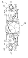
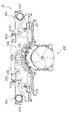
図1はパチンコ機10の正面図、図2はパチンコ機10の斜視図、図3はパチンコ機10の前面枠の斜視図である。図1および図2に示すように、パチンコ機10は、当該パチンコ機10の外殻を形成する外枠11と、この外枠11の一側部に開閉可能に支持された内枠12とを備えている。以下に、外枠11と内枠12との構成を個別に説明する。
(Configuration of front side of pachinko machine)
1 is a front view of the pachinko machine 10, FIG. 2 is a perspective view of the pachinko machine 10, and FIG. 3 is a perspective view of a front frame of the pachinko machine 10. As shown in FIGS. 1 and 2, the pachinko machine 10 includes an outer frame 11 that forms an outer shell of the pachinko machine 10, and an inner frame 12 that is supported on one side of the outer frame 11 so as to be opened and closed. I have. Below, the structure of the outer frame 11 and the inner frame 12 is demonstrated separately.
上記外枠11は、木製の板材により全体として矩形状に構成され、小ネジ等の離脱可能な締結具により各板材が組み付けられている。なお、外枠11は樹脂やアルミニウム等の軽金属により構成されていてもよい。このように構成することにより、パチンコ機の軽量化を図ることができるからである。
The outer frame 11 is formed in a rectangular shape as a whole by a wooden plate material, and each plate material is assembled by a detachable fastener such as a small screw. The outer frame 11 may be made of a light metal such as resin or aluminum. This is because such a configuration can reduce the weight of the pachinko machine.
一方、上記内枠12の開閉軸線はパチンコ機10の正面からみてハンドル(後述する遊技球発射ハンドル18)設置箇所の反対側(図1のパチンコ機10の左側)で上下に延びるように設定されており、この開閉軸線を軸心にして内枠12が前方側に十分に開放できるようになっている。このような構成とするのは、内枠12の開閉軸線がハンドル設置箇所側(図1のパチンコ機10の右側)で上下方向にあるとすると、内枠12を開放する際に遊技球発射ハンドル18の頭部等が隣なりのパチンコ機やカードユニット(球貸しユニット)に干渉することになり、内枠12を十分に開放できないからである。また、内枠12は合成樹脂、具体的にはABS(アクリロニトリル−ブタジエン−スチレン)樹脂から成る。こうすることで、粘性が高く衝撃に強くでき、低コストで製造できるという利点が発揮される。
On the other hand, the opening / closing axis of the inner frame 12 is set so as to extend vertically on the opposite side (left side of the pachinko machine 10 in FIG. 1) from the position where the handle (game ball launching handle 18 described later) is installed as viewed from the front of the pachinko machine 10. The inner frame 12 can be sufficiently opened to the front side with the opening / closing axis as the axis. If the opening / closing axis of the inner frame 12 is in the vertical direction on the handle installation location side (the right side of the pachinko machine 10 in FIG. 1), the game ball launching handle is opened when the inner frame 12 is opened. This is because the 18 heads and the like interfere with adjacent pachinko machines and card units (ball lending units), and the inner frame 12 cannot be fully opened. The inner frame 12 is made of a synthetic resin, specifically, ABS (acrylonitrile-butadiene-styrene) resin. By doing so, the advantages of high viscosity and high impact resistance and low cost production are exhibited.
また、内枠12は、その最下部に下皿ユニット13を有し、内枠12の左側の上下方向の開閉軸線を軸心にして開閉自在に取り付けられた前面枠セット14と、樹脂ベース25(図5参照)と、この樹脂ベース25の後側に取り付けられる後述の遊技盤30とを備えている。これらの各構成を以下に詳細に説明する。
Further, the inner frame 12 has a lower pan unit 13 at the lowermost part thereof, and a front frame set 14 attached to the left and right sides of the inner frame 12 so as to be openable and closable about a vertical opening / closing axis, and a resin base 25. (See FIG. 5) and a game board 30 (to be described later) attached to the rear side of the resin base 25. Each of these configurations will be described in detail below.
上記下皿ユニット13は、前面枠セット14の一部として前面枠ベース部材に固定されている。この下皿ユニット13の前面側には、下皿15と球抜きレバー17と遊技球発射ハンドル18と演出ボタン79が設けられている。球受皿としての下皿15は、下皿ユニット13のほぼ中央部に設けられており、後述の上皿が満タンになった場合等に排出口16より排出される遊技球を停留する役割がある。上記球抜きレバー17は、下皿15内の遊技球を抜くためのものであり、この球抜きレバー17を図1で左側に移動させることにより、下皿15の底面の所定箇所が開口され、下皿15内に停留された遊技球を下皿15の底面の開口部分を通して遊技者の持球貯留箱(ドル箱)に排出することができる。上記遊技球発射ハンドル18は、下皿15よりも右方で手前側に突出するように配設されている。遊技者による遊技球発射ハンドル18の操作に応じて、発射ソレノイドを備えた遊技球発射装置によって遊技球が後述する遊技盤30の方へ打ち込まれるようになっている。前面枠セット14の上部には、スピーカからの音を出力するための音出力口24が設けられている。
The lower plate unit 13 is fixed to the front frame base member as a part of the front frame set 14. On the front side of the lower plate unit 13, a lower plate 15, a ball removal lever 17, a game ball launching handle 18, and an effect button 79 are provided. The lower tray 15 serving as a ball receiving tray is provided at substantially the center of the lower tray unit 13 and plays a role of stopping a game ball discharged from the discharge port 16 when the upper tray described later becomes full. is there. The ball removal lever 17 is for removing a game ball in the lower tray 15, and by moving the ball removal lever 17 to the left in FIG. 1, a predetermined location on the bottom surface of the lower tray 15 is opened. The game ball stopped in the lower plate 15 can be discharged to the player's ball storage box (dollar box) through the opening on the bottom surface of the lower plate 15. The game ball launching handle 18 is disposed so as to protrude to the front side on the right side of the lower plate 15. In accordance with the operation of the game ball launching handle 18 by the player, the game ball is driven toward a game board 30 described later by a game ball launching device having a launch solenoid. A sound output port 24 for outputting sound from a speaker is provided at the upper part of the front frame set 14.
一方、前面枠セット14の下部(上述の下皿15の上方位置)には、遊技球の受皿としての上皿19が前面枠セット14と一体的に設けられている。この上皿19は、遊技球を一旦貯留し、一列に整列させながら遊技球発射装置38の方へ導出するための球受皿である。また、上皿19の左下方には、装飾図柄表示装置42の背景を変える等の操作を遊技者が行なうための演出ボタン79が設けられている。
On the other hand, an upper plate 19 as a receiving tray for game balls is provided integrally with the front frame set 14 at a lower portion of the front frame set 14 (above the lower plate 15 described above). The upper tray 19 is a ball receiving tray for temporarily storing the game balls and guiding them to the game ball launching device 38 while aligning them in a line. In addition, an effect button 79 for the player to perform an operation such as changing the background of the decorative symbol display device 42 is provided at the lower left of the upper plate 19.
加えて、前面枠セット14にはその周囲(例えばコーナー部分)に各種ランプ等の発光手段が設けられている。これら発光手段は、大当たり遊技状態時等における遊技状態の変化に応じて点灯、点滅のように発光態様が変更制御され遊技中の演出効果を高める役割を果たすものである。例えば、窓部101の周縁には、LED等の発光手段を内蔵した環状電飾部102が左右対称に設けられ、大当たり遊技状態時に点灯や点滅を行うことにより、大当たり遊技状態中であることを報知する構成である。
In addition, the front frame set 14 is provided with light emitting means such as various lamps around it (for example, a corner portion). These light emitting means play a role of enhancing the effect of the game during the game by changing and controlling the light emission mode such as lighting and blinking according to the change of the game state in the big hit game state or the like. For example, at the periphery of the window portion 101, an annular illumination portion 102 containing a light emitting means such as an LED is provided symmetrically, and lighting or blinking in the big hit gaming state, it is in a big hit gaming state It is the structure which alert | reports.
また、窓部101の下方には貸球操作部120が配設されており、貸球操作部120には球貸しボタンと、返却ボタンと、度数表示部とが設けられている。パチンコ機10の側方に配置された図示しないカードユニット(球貸しユニット)に紙幣やカード等を投入した状態で貸球操作部120が操作されると、その操作に応じて遊技球の貸出が行われる。球貸しボタンは、カード等(記録媒体)に記録された情報に基づいて貸出球を得るために操作されるものであり、カード等に残額が存在する限りにおいて貸出球が上皿19に供給される。返却ボタンは、カードユニットに挿入されたカード等の返却を求める際に操作される。度数表示部はカード等の残額情報を表示するものである。なお、カードユニットを介さずに球貸し装置部から上皿に遊技球が直接貸し出されるパチンコ機、いわゆる現金機では貸球操作部120が不要となる。故に、貸球操作部120の設置部分に、飾りシール等が付されるようになっている。これにより、カードユニットを用いたパチンコ機と現金機との貸球操作部の共通化が図れる。
In addition, a ball lending operation unit 120 is disposed below the window unit 101, and the ball lending operation unit 120 is provided with a ball lending button, a return button, and a frequency display unit. When the ball lending operation unit 120 is operated with a bill or a card inserted in a card unit (ball lending unit) (not shown) arranged on the side of the pachinko machine 10, a game ball is lent according to the operation. Done. The ball lending button is operated to obtain a lending ball based on information recorded on a card or the like (recording medium), and the lending ball is supplied to the upper plate 19 as long as there is a remaining amount on the card or the like. The The return button is operated when requesting the return of a card or the like inserted into the card unit. The frequency display section displays remaining amount information such as a card. Note that the ball lending operation unit 120 is not required for a pachinko machine in which a game ball is directly rented from the ball lending device unit to the upper plate without using a card unit, that is, a so-called cash machine. Therefore, a decorative seal or the like is attached to the installation portion of the ball rental operation unit 120. Thereby, the common use of the lending operation unit of the pachinko machine using the card unit and the cash machine can be achieved.
次に、図4を用いて遊技盤30の構成を説明する。図4は遊技盤30の構成を示す正面図である。遊技盤30は、一般入賞口を備える一般入賞装置、可変入賞装置32、上始動口33aと下始動口33b(作動チャッカ33bで構成)と一対の開閉羽根60とを備える始動入賞装置33、通過口を備える作動入賞装置34(スルーゲートで構成)、主表示ユニット371、装飾図柄表示装置42を備える可変表示装置ユニット35等が設けられている。これらの一般入賞装置、可変入賞装置32、始動入賞装置33、作動入賞装置34、可変表示装置ユニット35等は、遊技盤30における、ルータ加工によって形成された各貫通穴にそれぞれに配設され、遊技盤30前面側から木ネジ等により取り付けられている。また、下始動口33bの入口には、一対の開閉羽根60が設けられており、遊技球を案内する開放位置と、下始動口33b内に遊技球が入りにくくなる(入らない)閉塞位置を採りうる。開閉羽根60は、遊技盤30の裏面側に配設されたソレノイドSL1によって駆動される。また、上始動口33aの下方には、大入賞口(収容部の入口)61が配置されている。大入賞口61については、後に言及する。大入賞口61内には、入球検出スイッチSW1が設けられている。
Next, the configuration of the game board 30 will be described with reference to FIG. FIG. 4 is a front view showing the configuration of the game board 30. The game board 30 includes a general winning device having a general winning port, a variable winning device 32, a starting winning device 33 having an upper starting port 33a and a lower starting port 33b (configured by an operation chucker 33b), and a pair of opening and closing blades 60, and passing. An operation winning device 34 (including a through gate) having a mouth, a main display unit 371, a variable display device unit 35 having a decorative symbol display device 42, and the like are provided. These general winning devices, variable winning device 32, starting winning device 33, operating winning device 34, variable display device unit 35, etc. are respectively disposed in each through hole formed by router processing in game board 30, It is attached from the front side of the game board 30 with wood screws or the like. In addition, a pair of opening and closing blades 60 are provided at the entrance of the lower start port 33b, and an open position for guiding the game ball and a closed position where the game ball is difficult to enter (does not enter) into the lower start port 33b. Can be taken. The opening / closing blade 60 is driven by a solenoid SL1 disposed on the back side of the game board 30. In addition, a large winning opening (inlet of the accommodating portion) 61 is disposed below the upper start opening 33a. The special winning opening 61 will be described later. In the special winning opening 61, a ball detection switch SW1 is provided.
前述の一般入賞装置、可変入賞装置32および始動入賞装置33に遊技球が入球し、当該入球が後述する検出スイッチ(入賞口スイッチ、カウントスイッチ、作動口スイッチ等)で検出され、この検出スイッチの出力に基づいて、上皿19(または下皿15)へ所定数の賞品球が払い出される。その他に、遊技盤30にはアウト口36が設けられており、各種入賞装置等に入球しなかった遊技球はこのアウト口36を通って図示しない球排出路の方へと案内されるようになっている。遊技盤30には、遊技球の落下方向を適宜分散、調整等するために多数の釘が植設されているとともに、各種部材(役物)が配設されている。
A game ball enters the above-described general winning device, variable winning device 32, and starting winning device 33, and the received ball is detected by a detection switch (a winning port switch, a count switch, an operating port switch, etc.), which will be described later, and this detection. Based on the output of the switch, a predetermined number of prize balls are paid out to the upper plate 19 (or the lower plate 15). In addition, the game board 30 is provided with an out port 36, and game balls that have not entered the various winning devices etc. are guided through the out port 36 to a ball discharge path (not shown). It has become. A number of nails are implanted in the game board 30 in order to appropriately disperse and adjust the falling direction of the game balls, and various members (instruments) are arranged.
主表示ユニット371は、後述する主制御装置261が直接的に制御する表示装置ユニットであり、右側辺が上下に直線状に延び、該右側辺の下端から左側辺が遊技領域の右上部に沿って弧状に内側へ湾曲しながら左上へ延びて、全体としてやや上下に長い概略三角形の正面形状を有し、前後に遊技球の直径よりやや大きい程度の厚みを有する立体状の外形を有する部品となっている。主表示ユニット371は、遊技盤30の前面における右上部にネジ固定されている。主表示ユニット371における左上の上面部は左下方へやや下傾するように形成され、その中央部は、遊技球の最大飛翔部分に対応する外レール52の先端部に近接し、この部位の上に、ゴム板よりなる返しゴム371Rが取り付けられている。この返しゴム371Rにより、所定以上の勢いで発射された遊技球が当たって跳ね返されるようになっている。主表示ユニット371の前面部には、左上端近傍から下端部の近傍まで左側辺に沿って弧状に延びる正面形状を有して内奥側へ段状に凹入する表示部371Mが形成されている。
The main display unit 371 is a display device unit that is directly controlled by a main control device 261, which will be described later. The right side extends linearly up and down, and the left side extends from the lower end of the right side along the upper right part of the game area. A part having a three-dimensional outer shape that has a generally triangular front shape that is slightly longer in the vertical direction and has a thickness that is slightly larger than the diameter of the game ball. It has become. The main display unit 371 is screwed to the upper right part of the front surface of the game board 30. The upper left upper surface portion of the main display unit 371 is formed so as to be inclined slightly downward to the lower left, and the central portion thereof is close to the front end portion of the outer rail 52 corresponding to the maximum flying portion of the game ball. Further, a return rubber 371R made of a rubber plate is attached. The return rubber 371R hits and rebounds the game ball launched at a predetermined momentum or more. A display portion 371M having a front shape extending in an arc shape along the left side from the vicinity of the upper left end to the vicinity of the lower end portion and recessed in a step shape inward is formed on the front surface portion of the main display unit 371. Yes.
上記表示部371Mには、第1特別図柄表示装置、第2特別図柄表示装置、第1特別図柄保留表示装置、第2特別図柄保留表示装置、普通図柄表示装置、普通図柄保留表示装置および状態報知用表示装置が配置されている。第1特別図柄表示装置は、上始動口33aへの遊技球の入賞を契機に変動表示される第1特別図柄を表示するものであり、第2特別図柄表示装置は、下始動口33bへの遊技球の入賞を契機に変動表示される第2特別図柄を表示するものである。なお、各特別図柄は、上記第1特別図柄表示装置および第2特別図柄表示装置において同時に変動表示されることがなく入賞順に従って順次行われるため、装飾図柄表示装置42においては共通の装飾図柄によって特別図柄に対応する表示が行われるようになっている。第1特別図柄保留表示装置は、第1特別図柄の保留数を表示するものであり、第2特別図柄保留表示装置は、第2特別図柄の保留数を表示するものである。これら第1特別図柄保留表示装置および第2特別図柄保留表示装置はそれぞれ、複数個のLEDで構成され、このうちの一部あるいは全部を点灯又は点滅させることにより最大で4個までの保留数を表示するようになっている。なお、センターフレーム43の下部には、2色の発光が可能な合計4個のランプよりなる保留ランプ800aが装飾図柄表示装置42の下辺に沿って配列されており、この保留ランプ800aによって表示される装飾図柄の保留数は、遊技状態(後述するサポート状態か否か)に応じて、上記第1特別図柄保留表示装置および第2特別図柄保留表示装置のうち何れかが表示する保留数と対応するようになっている。普通図柄表示装置は、作動入賞装置34における通過口への遊技球の入賞を契機に変動表示される普通図柄を表示するものであり、2個のLEDで構成され、一方のLEDのみを点灯させることで外れを表示し、両方を点灯させることで当りを表示するようになっている。普通図柄保留表示装置は、普通図柄の保留数を表示するものであり、複数個のLEDで構成され、このうちの一部あるいは全部を点灯又は点滅させることにより最大で4個までの保留数を表示するようになっている。状態報知用表示装置は、遊技状態の種別を表示するものであり、複数個のLEDで構成されている。これらのLEDがそれぞれ消灯、点灯、点滅の何れかに変化し、全消灯を除く多数通りの組み合わせによって、1.通常遊技状態(大当たり乱数カウンタC1の抽選が低確率であり、サポート状態ではない)、2.時短状態(大当たり乱数カウンタC1の抽選が低確率であり、サポート状態)、3.潜伏高確率状態(大当たり乱数カウンタC1の抽選が高確率であり、サポート状態ではない)、4.高確率状態(大当たり乱数カウンタC1の抽選が高確率であり、サポート状態)、及び5.大当たり状態の何れかを表示するようになっており、大当たり状態を表示するのに際してはその大当たりの最大ラウンド数によって異なる表示が行われる。
The display unit 371M includes a first special symbol display device, a second special symbol display device, a first special symbol hold display device, a second special symbol hold display device, a normal symbol display device, a normal symbol hold display device, and a state notification. Display device is arranged. The first special symbol display device displays a first special symbol that is variably displayed when a game ball is won in the upper start port 33a, and the second special symbol display device displays the first special symbol display device on the lower start port 33b. A second special symbol that is displayed in a variable manner when a game ball is won is displayed. Each special symbol is not displayed in the first special symbol display device and the second special symbol display device at the same time, but is sequentially displayed according to the winning order. Therefore, the decorative symbol display device 42 uses a common decorative symbol. The display corresponding to the special symbol is performed. The first special symbol hold display device displays the hold number of the first special symbol, and the second special symbol hold display device displays the hold number of the second special symbol. Each of the first special symbol hold display device and the second special symbol hold display device is composed of a plurality of LEDs, and by turning on or blinking some or all of them, the number of hold up to four can be obtained. It is supposed to be displayed. A holding lamp 800a composed of a total of four lamps capable of emitting two colors is arranged along the lower side of the decorative symbol display device 42 at the lower part of the center frame 43, and is displayed by the holding lamp 800a. The number of decoration symbols to be held corresponds to the number of holds displayed by either the first special symbol hold display device or the second special symbol hold display device according to the game state (whether the support state will be described later). It is supposed to be. The normal symbol display device displays a normal symbol that is variably displayed in response to the winning of a game ball at the passing port in the operation winning device 34, and is composed of two LEDs, and only one of the LEDs is lit. In this case, a miss is displayed, and a hit is displayed by lighting both. The normal symbol hold display device displays the number of normal symbols held and is composed of a plurality of LEDs. By lighting or blinking some or all of these LEDs, up to four hold numbers can be displayed. It is supposed to be displayed. The state notification display device displays a type of gaming state, and includes a plurality of LEDs. These LEDs change to any one of light-off, light-on, and light-blink, and there are a number of combinations except for light-off. 1. Normal gaming state (the lottery of the jackpot random number counter C1 has a low probability and is not in a support state). 2. Short-time state (Lottery of jackpot random number counter C1 is low probability and support state); 3. Hidden high probability state (the lottery of the jackpot random number counter C1 has a high probability and is not in the support state). 4. High probability state (lottery of jackpot random number counter C1 is high probability, support state), and One of the jackpot states is displayed. When the jackpot state is displayed, different display is performed depending on the maximum number of rounds of the jackpot.
上記装飾図柄表示装置42は液晶表示装置として構成されており、後述する表示制御装置により表示内容が制御される。装飾図柄表示装置42には、例えば上、中、及び下の3箇所に識別情報としての図柄(装飾図柄)が表示される。これら図柄がスクロールされて装飾図柄表示装置42に可変表示されるようになっている。なお本形態では、装飾図柄表示装置42(液晶表示装置)は例えば10インチ或いは12インチサイズの大型の液晶ディスプレイを備えている。遊技球が始動入賞装置33を通過した回数は最大4回まで保留され、その保留回数が保留ランプ800aにて点灯表示されるようになっているが、この保留ランプ800aが表示する保留回数は、装飾図柄表示装置42の一部(具体的には右下部)にも表示される。この保留表示は、保留数に対応する数のキャラクタ画像が並列的に表示されるものである。
The decorative design display device 42 is configured as a liquid crystal display device, and display contents are controlled by a display control device to be described later. On the decorative symbol display device 42, for example, symbols (decorative symbols) as identification information are displayed at three locations, upper, middle, and lower. These symbols are scrolled and variably displayed on the decorative symbol display device 42. In this embodiment, the decorative symbol display device 42 (liquid crystal display device) is provided with a large liquid crystal display having a size of 10 inches or 12 inches, for example. The number of times that the game ball has passed through the start winning device 33 is held up to a maximum of 4 times, and the number of times the game ball is lit is displayed on the hold lamp 800a. The hold number displayed by the hold lamp 800a is as follows: It is also displayed on a part of the decorative symbol display device 42 (specifically, the lower right portion). In this hold display, the number of character images corresponding to the number of holds is displayed in parallel.
上記可変入賞装置32は、通常は遊技球が入賞できない又は入賞し難い閉状態になっており、大当たりの際に遊技球が入賞しやすい開状態と通常の閉状態とに繰り返し作動されるようになっているが、その具体的な構成については後述する。簡略に触れれば、特別図柄表示装置が特定の表示態様となった場合(装飾図柄表示装置42の停止後の確定図柄が予め設定した特定の図柄の組み合せとなった場合)に特別遊技状態が発生する。そして、可変入賞装置32が受球状態となり、遊技球の入賞を許す。具体的には、所定時間(例えば30秒)の経過又は所定個数(例えば10個)の入賞を1ラウンドとして、可変入賞装置32の受球状態が所定回数繰り返し開放される。
The variable winning device 32 is normally in a closed state in which a game ball cannot be won or difficult to win, and is repeatedly operated in an open state and a normal closed state in which a game ball is easy to win in a big win. However, the specific configuration will be described later. In short, when the special symbol display device is in a specific display mode (when the confirmed symbol after the decoration symbol display device 42 is stopped is a combination of specific symbols set in advance), the special gaming state is Occur. Then, the variable winning device 32 is in a ball receiving state and allows a game ball to be won. Specifically, the ball receiving state of the variable winning device 32 is repeatedly released a predetermined number of times, with a predetermined time (for example, 30 seconds) or a predetermined number (for example, 10) of winnings taken as one round.
また、図4に示すように、遊技盤30には、遊技球発射装置から発射された遊技球を遊技盤30上部へ案内するためのレールユニット50が取り付けられており、遊技球発射ハンドル18の回動操作に伴い発射された遊技球はレールユニット50を通じて所定の遊技領域に案内されるようになっている。レールユニット50はリング状をなす金属板にて構成されており、内外二重に一体形成された内レール51と外レール52とを有する。内レール51および外レール52の後側端縁(遊技盤30に対向する端縁)には、所定間隔をおいて複数個所に鋲56が設けられており、内レール51および外レール52は該鋲56を打ちつけるようにして遊技盤30に取り付けられている。内レール51は上方の約1/4ほどを除いて略円環状に形成され、一部(主に左側部)が内レール51に向かい合うようにして外レール52が形成されている。かかる場合、内レール51と外レール52とにより誘導レールが構成され、これら各レール51、52が所定間隔を隔てて並行する部分(向かって左側の部分)により球案内通路が形成されている。なお、球案内通路は、遊技盤30との当接面を有した溝状、すなわち手前側を開放した溝状に形成されている。
As shown in FIG. 4, a rail unit 50 for guiding the game ball launched from the game ball launching device to the upper part of the game board 30 is attached to the game board 30. A game ball launched in accordance with the turning operation is guided to a predetermined game area through the rail unit 50. The rail unit 50 is composed of a ring-shaped metal plate, and includes an inner rail 51 and an outer rail 52 that are integrally formed in an inner and outer double. On the rear edge of the inner rail 51 and the outer rail 52 (edge facing the game board 30), a plurality of hooks 56 are provided at predetermined intervals, and the inner rail 51 and the outer rail 52 are The game board 30 is attached to the game board 30 so as to hit the basket 56. The inner rail 51 is formed in a substantially annular shape except for about 1/4 of the upper part, and the outer rail 52 is formed so that a part (mainly the left side) faces the inner rail 51. In such a case, a guide rail is constituted by the inner rail 51 and the outer rail 52, and a spherical guide passage is formed by a portion (the left portion facing) where the rails 51 and 52 are parallel to each other at a predetermined interval. The ball guide passage is formed in a groove shape having a contact surface with the game board 30, that is, a groove shape in which the front side is opened.
内レール51の先端部分(図4の左上部)には戻り球防止部材53が取着されている。これにより、一旦、内レール51および外レール52間の球案内通路から遊技盤30の上部へと案内された遊技球が再度球案内通路内に戻ってしまうといった事態が防止されるようになっている。
A return ball preventing member 53 is attached to the tip of the inner rail 51 (upper left portion in FIG. 4). This prevents a situation in which the game ball once guided from the ball guide path between the inner rail 51 and the outer rail 52 to the upper part of the game board 30 returns to the ball guide path again. Yes.
尚、遊技領域は、レールユニット50の内周部(内外レール)と主表示ユニット371の斜辺とにより略円形状に区画形成されており、特に本形態では、遊技盤30の盤面上に区画される遊技領城が従来よりもはるかに大きく構成されている。
The game area is partitioned into a substantially circular shape by the inner peripheral portion (inner / outer rail) of the rail unit 50 and the oblique side of the main display unit 371. In particular, in this embodiment, the game area is partitioned on the board surface of the game board 30. The game castle is much larger than before.
さらに、遊技盤30の右側縁部には、側端レール50Sが配設されている。側端レール50Sは、内レール51および外レール52とは別体として構成され、また内レール51および外レール52からは間隔を置いて独立に配置されているが、外レール52とおおよそ同一の円周上に位置して遊技領域の右端部を区画しており、即ちレールユニット50の一部(右端部)を構成している。この側端レール50Sの構成および取付構造については後述する。
Further, a side end rail 50 </ b> S is disposed on the right edge of the game board 30. The side end rail 50 </ b> S is configured as a separate body from the inner rail 51 and the outer rail 52, and is disposed independently from the inner rail 51 and the outer rail 52, but is substantially the same as the outer rail 52. It is located on the circumference and demarcates the right end portion of the game area, that is, constitutes a part (right end portion) of the rail unit 50. The configuration and mounting structure of the side end rail 50S will be described later.
(パチンコ機の背面構成)
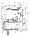
次に、パチンコ機10の背面の構成を説明する。図5はパチンコ機10の背面の構成を示す分解斜視図である。
(Back view of pachinko machine)
Next, the configuration of the back surface of the pachinko machine 10 will be described. FIG. 5 is an exploded perspective view showing the configuration of the back surface of the pachinko machine 10.
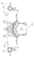
先ず、パチンコ機10の背面構成について全体の概要を説明する。パチンコ機10にはその背面(実際には内枠12および遊技盤30の背面)において、各種制御基板が上下左右に並べられるようにしてまたは前後に重ねられるようにして配置されており、さらに、遊技球を供給するための遊技球供給装置(払出機構)や樹脂製の裏カバー(保護カバー)等が取り付けられている。本形態では、各種制御基板を3つの取付台に分けて搭載して3つの制御基板ユニットを構成し、それら制御基板ユニットを個別に内枠12または遊技盤30の裏面に装着するようにしている。この場合、主制御基板、電源監視基板、これら基板を収容する基板ボックスおよび該基板ボックスを封印する封印ユニットから構成される主制御装置261を一つにユニット化し、表示制御基板、該表示制御基板を収容する基板ボックスおよび装飾図柄表示装置42から構成される表示制御装置45とサブ制御基板および該サブ制御基板を収容する基板ボックスから構成されるサブ制御装置262とを後述する外包部材82に搭載してユニット化し、さらに払出制御基板、該払出制御基板を収容する基板ボックス(払出制御基板ケース)および該基板ボックスを封印する封印ユニットから構成される払出制御装置311と電源基板、発射制御基板およびこれら基板を収容する基板ボックス(電源・発射制御基板ケース203A)から構成される電源・発射制御装置とを1つの取付台に搭載してユニット化している。ここでは便宜上、各ユニットを上記の順に「第1制御基板ユニット201」、「第2制御基板ユニット202」および「第3制御基板ユニット203」と称することとする。
First, an overall outline of the rear configuration of the pachinko machine 10 will be described. On the back surface of the pachinko machine 10 (actually, the back surface of the inner frame 12 and the game board 30), various control boards are arranged so as to be lined up and down, left and right, or stacked in front and back, A game ball supply device (payout mechanism) for supplying game balls, a resin back cover (protective cover), and the like are attached. In this embodiment, various control boards are divided into three mounting bases to form three control board units, and these control board units are individually attached to the inner frame 12 or the back of the game board 30. . In this case, the main control device 261 composed of a main control board, a power supply monitoring board, a board box that accommodates these boards, and a sealing unit that seals the board box is unitized into one unit, and the display control board and the display control board A display control device 45 composed of a substrate box for housing the decorative design display device 42 and a sub control device 262 composed of a sub control substrate and a substrate box for housing the sub control substrate are mounted on an outer packaging member 82 to be described later. A payout control board 311 comprising a payout control board, a board box (payout control board case) for housing the payout control board, and a sealing unit for sealing the board box; a power supply board; a launch control board; It consists of a board box (power supply / launch control board case 203A) that houses these boards. It is unitized by mounting a power-firing controller in a single mount. Here, for convenience, each unit will be referred to as a “first control board unit 201”, a “second control board unit 202”, and a “third control board unit 203” in the order described above.
また、払出機構および裏カバー(保護カバー)も上記第3制御基板ユニット203に一体化されており、一般に樹脂部分を裏パックと称することもあるため、ここでは第3制御基板ユニット203を「裏パックユニット203」とも称する。各ユニット201〜203の詳細な構成については後述する。
Further, the payout mechanism and the back cover (protective cover) are also integrated with the third control board unit 203, and the resin part is generally referred to as a back pack. Also referred to as “pack unit 203”. The detailed configuration of each unit 201 to 203 will be described later.
第1制御基板ユニット201は、後述するように、取り外す場合には工具で封止状態を解除する必要があるが取付はネジ等の締結具も工具も何ら要することなく行い得るよう構成されており、第2制御基板ユニット202および裏パックユニット203は、ユニット単位で何ら工具等を用いずに着脱できるよう構成されている。更に、これに加え、各ユニット201〜203は、一部に支軸部を設けて内枠12または遊技盤30の裏面に対して開閉できる構成となっている。これは、各ユニット201〜203やその他構成が前後に重ねて配置されても、隠れた構成等を容易に確認することを可能とするための工夫でもある。
As will be described later, the first control board unit 201 is configured to be able to be attached without using a fastener such as a screw or a tool, although it is necessary to release the sealed state with a tool when removing the first control board unit 201. The second control board unit 202 and the back pack unit 203 are configured to be detachable without using any tools or the like in units. Further, in addition to this, each of the units 201 to 203 has a structure in which a support shaft portion is provided in part and can be opened and closed with respect to the inner frame 12 or the back surface of the game board 30. This is also a device for making it possible to easily check a hidden configuration or the like even if the units 201 to 203 and other configurations are arranged one behind the other.
上述した第1制御基板ユニット201は、その遊技の進行を統括する主制御基板及び電源の監視を司る電源監視基板を有する。上記主制御基板と電源監視基板とは透明樹脂材料等よりなる基板ボックスに収容されて構成されている。この基板ボックスは、略直方体形状のボックスベースと該ボックスベースの開口部を覆うボックスカバーとを備えており、これらボックスベースとボックスカバーとは封印ユニットによって開封不能に連結されることにより、基板ボックスが封印される。
The first control board unit 201 described above has a main control board that controls the progress of the game and a power supply monitoring board that manages power supply monitoring. The main control board and the power monitoring board are housed in a board box made of a transparent resin material or the like. The board box includes a box base having a substantially rectangular parallelepiped shape and a box cover that covers an opening of the box base. The box base and the box cover are connected to each other by a sealing unit so that the board box cannot be opened. Is sealed.
尚、封印ユニットはボックスベースとボックスカバーとを開封不能に連結する構成であれば任意の構成が適用でき、また、封印ユニットによる封印処理は、その封印後の不正な開封を防止し、また万一不正開封が行われてもそのような事態を早期にかつ容易に発見可能とするものである。
Any configuration can be applied to the sealing unit as long as the box base and the box cover are connected so as not to be opened, and the sealing process by the sealing unit prevents unauthorized opening after the sealing. Even if an unauthorized opening is performed, such a situation can be detected early and easily.
第2制御基板ユニット202は、主制御基板からの指示に従い前記装飾図柄表示装置42の表示制御を司る表示制御装置45と主制御基板からの指示に従い音声ランプ制御を司るサブ制御基板とを有する。上記表示制御装置45は、装飾図柄表示装置42および表示制御基板がユニットとして構成され、透明樹脂材料等よりなる基板ボックスに収容されて後述する外包部材82の背面側に取り付けられている。上記サブ制御基板は透明樹脂材料等よりなる基板ボックスに収容され、上記表示制御装置45の背面側に取り付けられている。
The second control board unit 202 includes a display control device 45 that controls display of the decorative symbol display device 42 according to an instruction from the main control board, and a sub control board that controls sound lamp control according to an instruction from the main control board. The display control device 45 includes a decorative symbol display device 42 and a display control board as a unit, is accommodated in a board box made of a transparent resin material or the like, and is attached to the back side of an outer packaging member 82 described later. The sub control board is accommodated in a board box made of a transparent resin material or the like, and is attached to the back side of the display control device 45.
次に、前記第3制御基板ユニット(裏パックユニット)203は、払出制御基板、電源基板、発射制御基板及びカードユニット接続基板を有している。上記払出制御基板により賞品球や貸出球の払出が制御され、上記電源基板および発射制御基板により各種制御装置等で要する所定の電源電圧が生成され出力されるとともに遊技者による遊技球発射ハンドル18の操作に従い発射ソレノイドの制御が行われる。また、上記カードユニット接続基板は、パチンコ機前面の貸球操作部120(図1参照)および図示しないカードユニットに電気的に接続され、遊技者による球貸し操作の指令を取り込んでそれを払出制御基板に出力するものである。なお、カードユニットを介さずに球貸し装置等から上皿に遊技球が直接貸し出される現金機では、カードユニット接続基板は不要である。
Next, the third control board unit (back pack unit) 203 has a payout control board, a power supply board, a firing control board, and a card unit connection board. The payout control board controls the payout of prize balls and rental balls, and the power supply board and the launch control board generate and output predetermined power supply voltages required by various control devices and the like, and the game ball launch handle 18 by the player The firing solenoid is controlled according to the operation. Also, the card unit connection board is electrically connected to the ball rental operation unit 120 (see FIG. 1) on the front surface of the pachinko machine and a card unit (not shown), and receives a command for a ball rental operation by a player and pays it out. Output to the substrate. Note that a card unit connection board is not required in a cash machine in which game balls are lent directly to the upper plate from a ball lending device or the like without using a card unit.
上記払出制御基板は、透明樹脂材料等よりなる払出制御基板ケース(図示せず)内に収納されており、上記電源基板および発射制御基板は、透明樹脂材料等よりなる電源・発射制御基板ケース203A内に収納されている。また、上記カードユニット接続基板は透明樹脂材料等よりなるカードユニット接続基板ケース(図示せず)内に収納されている。特に、払出制御基板では、前述した主制御基板と同様、基板ケース(被包手段)を構成するボックスベースとボックスカバーとが封印ユニット(封印手段)によって開封不能に連結されることにより、基板ボックスが封印される。
The payout control board is housed in a payout control board case (not shown) made of a transparent resin material or the like, and the power supply board and the fire control board are a power supply / fire control board case 203A made of a transparent resin material or the like. It is stored inside. The card unit connection board is housed in a card unit connection board case (not shown) made of a transparent resin material or the like. In particular, in the payout control board, the box base and the box cover constituting the board case (encapsulating means) are connected to each other by the sealing unit (sealing means) so as not to be opened, like the main control board described above. Is sealed.
上記払出制御基板は状態復帰スイッチと電気的に接続されており、例えば、払出モータ部の球詰まり等、払出エラーの発生時において状態復帰スイッチが押下されると、払出モータがゆっくりと正回転され、球詰まりの解消(正常状態への復帰)が図られるようになっている。
The payout control board is electrically connected to a state return switch.For example, when the state return switch is pressed when a payout error occurs, such as a ball clogging in the payout motor unit, the payout motor is slowly rotated forward. The ball clogging can be eliminated (return to normal state).
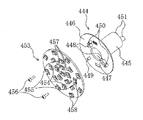
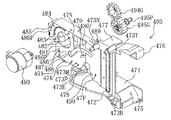
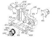
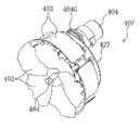
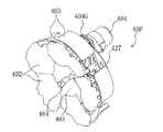
裏パックユニット203は、樹脂成形された裏パック351と遊技球の払出機構部352とを一体化したものである。
The back pack unit 203 is a unit in which a resin-formed back pack 351 and a game ball payout mechanism 352 are integrated.
裏パック351は例えばABS樹脂により成型されており、略平坦状のベース部353と、パチンコ機後方に突出し横長の略直方体形状をなす裏カバー部(保護カバー部)354とを有する。裏カバー部354は左右側面および上面が閉鎖されかつ下面のみが開放された形状をなし、少なくとも電動役物表示制御装置45を囲むのに十分な大きさを有する(但し本形態では、前述のサブ制御装置262も合わせて囲む構成となっている)。裏カバー部354の背面には多数の通気孔が設けられている。この通気孔は各々が長孔状をなし、それぞれの通気孔が比較的近い位置で隣り合うよう設けられている。従って、隣り合う通気孔間にある樹脂部分を切断することにより、裏パック351の背面を容易に開口させることができる。つまり、通気孔間の樹脂部分を切断してその内部の表示制御装置等を露出させることで、所定の検定等を容易に実施することができる。
The back pack 351 is formed of, for example, ABS resin, and includes a substantially flat base portion 353 and a back cover portion (protective cover portion) 354 that protrudes rearward from the pachinko machine and has a horizontally long substantially rectangular parallelepiped shape. The back cover portion 354 has a shape in which the left and right side surfaces and the upper surface are closed and only the lower surface is opened, and has a size sufficient to surround at least the electric accessory display control device 45 (however, in the present embodiment, the above-mentioned sub The control device 262 is also enclosed. A large number of ventilation holes are provided on the back surface of the back cover portion 354. Each of the vent holes has a long hole shape, and the vent holes are provided adjacent to each other at a relatively close position. Therefore, the back surface of the back pack 351 can be easily opened by cutting the resin portion between the adjacent vent holes. That is, a predetermined test or the like can be easily performed by cutting the resin portion between the air holes and exposing the display control device and the like inside the resin portion.
また、ベース部353には、裏カバー部354を迂回するようにして払出機構部352が配設されている。すなわち、裏パック351の最上部には上方に開口したタンク355が設けられており、このタンク355には遊技ホールの島設備から供給される遊技球が逐次補給される。タンク355の下方には、例えば横方向2列(2条)の球通路を有し下流側に向けて緩やかに傾斜するタンクレール356が連結され、さらにタンクレール356の下流側には縦向きにケースレール357が連結されている。払出装置358はケースレール357の最下流部に設けられ、払出モータ等の所定の電気的構成により必要個数の遊技球の払出が適宜行われる。そして、払出装置358より払い出された遊技球は図示しない払出通路等を通じて前記上皿19に供給される。
In addition, the base portion 353 is provided with a payout mechanism portion 352 so as to bypass the back cover portion 354. That is, a tank 355 opened upward is provided at the uppermost portion of the back pack 351, and game balls supplied from the island facilities of the game hall are sequentially supplied to the tank 355. Below the tank 355, for example, a tank rail 356 that has two rows (two rows) of ball passages in the horizontal direction and that is gently inclined toward the downstream side is connected. Further, the tank rail 356 is arranged vertically on the downstream side of the tank rail 356. A case rail 357 is connected. The payout device 358 is provided at the most downstream portion of the case rail 357, and a required number of game balls are paid out appropriately according to a predetermined electrical configuration such as a payout motor. The game balls paid out from the payout device 358 are supplied to the upper plate 19 through a payout passage or the like (not shown).
タンクレール356と、当該タンクレール356に振動を付加するためのバイブレータ359とが一体化するようにユニット化されており、仮にタンクレール356付近で球詰まりが生じた際、バイブレータ359が駆動されることで球詰まりが解消されるようになっている。
The tank rail 356 and a vibrator 359 for applying vibration to the tank rail 356 are unitized so as to be integrated. If a ball is clogged near the tank rail 356, the vibrator 359 is driven. In this way, the clogging of the balls is resolved.
上記払出機構部352には、前記払出制御基板から払出装置358への払出指令の信号を中継する払出中継基板381が設置されると共に、外部より主電源を取り込むための電源スイッチ基板382が設置されている。電源スイッチ基板382には、電圧変換器を介して例えば交流24Vの主電源が供給され、電源スイッチの切替操作により電源ONまたは電源OFFとされるようになっている。
The payout mechanism 352 is provided with a payout relay board 381 for relaying a payout command signal from the payout control board to the payout device 358, and a power switch board 382 for taking in the main power from the outside. ing. The power switch board 382 is supplied with, for example, AC 24V main power via a voltage converter, and is turned on or off by switching the power switch.
なお、内枠12の右上側には、内枠12が外枠11に対して開かれたことを検出する内枠開検出スイッチ(図示せず)が設けられており、内枠12が開かれると、内枠開検出スイッチからホール内(パチンコ店内)用コンピュータヘ出力されるようになっている。また、上記内枠開検出スイッチの左方には、前面枠開検出スイッチ(図示せず)が設けられており、前面枠セット14が開かれると、前面枠開検出スイッチからホール内(パチンコ店内)用コンピュータヘ出力されるようになっている。
An inner frame opening detection switch (not shown) for detecting that the inner frame 12 is opened with respect to the outer frame 11 is provided on the upper right side of the inner frame 12 so that the inner frame 12 is opened. And output from the inner frame open detection switch to the computer for the hall (in the pachinko parlor). In addition, a front frame opening detection switch (not shown) is provided on the left side of the inner frame opening detection switch. When the front frame set 14 is opened, the front frame opening detection switch is opened in the hall (in the pachinko store). ) Is output to the computer.
(パチンコ機の電気的構成及び各種制御処理)
次に、図8を参照して、本パチンコ機10の電気的構成について説明する。パチンコ機10は、電源装置313と、電源監視装置540と、主制御装置261と、サブ制御装置262と、払出制御装置311と、表示制御装置45等を備えている。以下に、これらの装置を個別に詳細に説明する。尚、電源監視装置540と主制御装置261とは、上記したように封印ユニットで封印されている。
(Electric configuration of pachinko machine and various control processes)
Next, the electrical configuration of the pachinko machine 10 will be described with reference to FIG. The pachinko machine 10 includes a power supply device 313, a power supply monitoring device 540, a main control device 261, a sub control device 262, a payout control device 311, a display control device 45, and the like. In the following, these devices will be described in detail individually. The power supply monitoring device 540 and the main control device 261 are sealed by the sealing unit as described above.
次いで、主制御装置261の構成について説明する。主制御装置261には、演算装置である1チップマイコンとしてのMPU501が搭載されている。MPU501には、該MPU501により実行される各種の制御プログラムや固定値データを記憶したROM502と、そのROM502内に記憶される制御プログラムの実行に際して各種のデータ等を一時的に記憶するためのメモリであるRAM503と、そのほか、割込回路やタイマ回路、データ送受信回路などの各種回路が内蔵されている。
Next, the configuration of the main controller 261 will be described. The main controller 261 is equipped with an MPU 501 as a one-chip microcomputer that is an arithmetic unit. The MPU 501 includes a ROM 502 that stores various control programs executed by the MPU 501 and fixed value data, and a memory that temporarily stores various data when the control program stored in the ROM 502 is executed. A certain RAM 503 and various other circuits such as an interrupt circuit, a timer circuit, and a data transmission / reception circuit are incorporated.
RAM503は、パチンコ機10の電源の遮断後においても電源装置313からバックアップ電圧が供給されてデータを保持(バックアップ)できる構成となっており、RAM503には、各種のデータ等を一時的に記憶するためのエリアが備えられている。
The RAM 503 is configured to retain (backup) data by being supplied with a backup voltage from the power supply device 313 even after the pachinko machine 10 is powered off. The RAM 503 temporarily stores various data and the like. There is an area for.
なお、MPU501のNMI端子(ノンマスカブル割込端子)には、停電等の発生による電源遮断時に、停電監視回路542からの停電信号SG1が入力されるように構成されており、その停電信号SG1がMPU501へ入力されると、停電時処理としてのNMI割込処理が即座に実行される。
Note that the power failure signal SG1 from the power failure monitoring circuit 542 is input to the NMI terminal (non-maskable interrupt terminal) of the MPU 501 when the power is shut down due to the occurrence of a power failure or the like. Is input immediately, the NMI interrupt process as a power failure process is immediately executed.
主制御装置261のMPU501には、アドレスバス及びデータバスで構成されるバスライン504を介して入出力ポート505が接続されている。入出力ポート505には、電源監視装置540内のRAM消去スイッチ回路543、払出制御装置311、発射制御装置312、サブ制御装置262、主表示ユニット371(第1特別図柄保留表示装置、第1特別図柄表示装置、第2特別図柄保留表示装置、第2特別図柄表示装置、普通図柄表示装置、普通図柄保留表示装置、状態報知用表示装置)や、その他図示しない入賞検知スイッチ群や不正検知スイッチ群などが接続されている。なお、装飾図柄保留表示装置800(保留ランプ800a)は、サブ制御装置262に従属する表示制御装置45に接続されている。
An input / output port 505 is connected to the MPU 501 of the main control device 261 via a bus line 504 including an address bus and a data bus. The input / output port 505 includes a RAM erasing switch circuit 543, a payout control device 311, a launch control device 312, a sub control device 262, a main display unit 371 (first special symbol hold display device, first special display device) in the power supply monitoring device 540. Symbol display device, second special symbol hold display device, second special symbol display device, normal symbol display device, normal symbol hold display device, status notification display device), and other winning detection switch group and fraud detection switch group not shown Etc. are connected. The decorative symbol hold display device 800 (hold lamp 800a) is connected to a display control device 45 subordinate to the sub control device 262.
払出制御装置311は、払出モータ358aにより賞球や貸し球の払出制御を行うものである。演算装置であるMPU511は、そのMPU511により実行される制御プログラムや固定値データ等を記憶したROM512と、ワークメモリ等として使用されるRAM513とを備えている。
The payout control device 311 controls payout of prize balls and rental balls by a payout motor 358a. The MPU 511 that is an arithmetic unit includes a ROM 512 that stores a control program executed by the MPU 511, fixed value data, and the like, and a RAM 513 that is used as a work memory or the like.
払出制御装置311のRAM513は、主制御装置261のRAM503と同様に、パチンコ機10の電源の遮断後においても電源装置313からバックアップ電圧が供給されてデータを保持(バックアップ)できる構成となっており、RAM513には、各種のデータ等を一時的に記憶するためのエリアが備えられている。
The RAM 513 of the payout control device 311 is configured to hold (backup) data by supplying a backup voltage from the power supply device 313 even after the power of the pachinko machine 10 is shut off, like the RAM 503 of the main control device 261. The RAM 513 is provided with an area for temporarily storing various data.
なお、主制御装置261のMPU501と同様、MPU511のNMI端子にも、停電時の発生による電源遮断時に停電監視回路542から停電信号SG1が入力されるように構成されており、その停電信号SG1がMPU511へ入力されると、停電時処理としてのNMI割込処理が即座に実行される。
As with the MPU 501 of the main controller 261, the power failure signal SG1 is also input to the NMI terminal of the MPU 511 from the power failure monitoring circuit 542 when the power is interrupted due to the occurrence of a power failure. When input to the MPU 511, an NMI interrupt process as a power failure process is immediately executed.
払出制御装置311のMPU511には、アドレスバス及びデータバスで構成されるバスライン514を介して入出力ポート515が接続されている。入出力ポート515には、主制御装置261、払出モータ358aがそれぞれ接続されている。
An input / output port 515 is connected to the MPU 511 of the payout control device 311 via a bus line 514 including an address bus and a data bus. A main controller 261 and a payout motor 358a are connected to the input / output port 515, respectively.
発射制御装置312は、発射ソレノイドによる遊技球の発射を許可又は禁止するものであり、発射ソレノイドは、所定条件が整っている場合に駆動が許可される。具体的には、払出制御装置311からカードユニットとの接続状態であることを示す接続信号が出力されていること、遊技者が遊技球発射ハンドル18に触れていることをセンサ信号により検出していること、発射を停止させるための発射停止スイッチが操作されていないことを条件に、発射制御装置312は発射許可信号を主制御装置261に出力する。発射許可信号を入力した主制御装置261は、発射ソレノイド制御信号を発射制御装置312に出力する。これにより発射制御装置312は発射ソレノイド制御信号に応じて発射ソレノイドを駆動し、その結果、遊技球発射ハンドルの操作量に応じた強さで遊技球が発射される。
The launch control device 312 permits or prohibits the launch of the game ball by the launch solenoid, and the launch solenoid is permitted to drive when a predetermined condition is met. Specifically, the sensor signal detects that a connection signal indicating that the payout control device 311 is connected to the card unit is output, and that the player is touching the game ball launching handle 18. The firing control device 312 outputs a firing permission signal to the main control device 261 on the condition that the firing stop switch for stopping the firing is not operated. The main controller 261 that has input the firing permission signal outputs a firing solenoid control signal to the firing controller 312. As a result, the launch control device 312 drives the launch solenoid in response to the launch solenoid control signal, and as a result, the game ball is launched with a strength corresponding to the amount of operation of the game ball launch handle.
サブ制御装置262は、主制御装置261からのコマンドに基づいて装飾図柄の変動表示に応じた演出用スピーカ810等の鳴動制御及び演出用ランプ811の点灯(点滅)制御、並びに、主制御装置261からのコマンドに基づいて表示制御装置45へのコマンドを編集して表示制御装置45に送信する機能を果たすものである。サブ制御装置262のMPU550には、そのMPU550により実行される制御プログラムや固定値データ等を記憶したROM551と、ワークメモリ等として使用されるRAM552とを備えている。MPU550には、アドレスバス及びデータバスで構成されるバスライン553を介して入出力ポート554が接続されている。入出力ポート554には、スピーカ、ランプ、装飾図柄表示装置42における変動表示中において所定の表示演出を実行させるための演出用ボタン79、及び主制御装置261がそれぞれ接続されている。演出用ボタン79としては、例えば所定のキャラクタが順次出現する態様によって大当たり状態の可能性が大きいことを予告するステップアップ予告等の表示演出用ボタン等が挙げられる。なお、演出用ボタン79が押されると、所定の演出実行のための演出指定コマンドが生成されて、装飾図柄表示装置42に送信されようになっている。
The sub control device 262 controls the ringing control of the effect speaker 810 and the like in accordance with the change display of the decoration symbol based on the command from the main control device 261, the lighting (flashing) control of the effect lamp 811, and the main control device 261. The function to edit the command to the display control device 45 based on the command from and send it to the display control device 45 is achieved. The MPU 550 of the sub-control device 262 includes a ROM 551 that stores a control program executed by the MPU 550, fixed value data, and the like, and a RAM 552 that is used as a work memory or the like. An input / output port 554 is connected to the MPU 550 via a bus line 553 composed of an address bus and a data bus. The input / output port 554 is connected to a speaker, a lamp, an effect button 79 for executing a predetermined display effect during variable display on the decorative symbol display device 42, and a main control device 261. Examples of the effect button 79 include a display effect button such as a step-up notice for notifying that the possibility of a big hit state is high depending on the manner in which predetermined characters appear sequentially. When an effect button 79 is pressed, an effect designation command for executing a predetermined effect is generated and transmitted to the decorative symbol display device 42.
表示制御装置45は、装飾図柄表示装置42における装飾図柄の変動表示を制御するものである。表示制御装置45は、ワークRAM等として使用されるRAM523を有するMPU521と、ROM(プログラムROM)522と、ビデオRAM524と、キャラクタROM525と、画像コントローラ526と、入力ポート527と、出力ポート529とを備えている。
The display control device 45 controls the variation display of the decorative symbols on the decorative symbol display device 42. The display control device 45 includes an MPU 521 having a RAM 523 used as a work RAM, a ROM (program ROM) 522, a video RAM 524, a character ROM 525, an image controller 526, an input port 527, and an output port 529. I have.
MPU521は、サブ制御装置262から送信されてくる図柄表示コマンド(停止図柄コマンド、変動パターンコマンド、確定コマンド等)を入力ポート527を介して受信するとともに、受信コマンドを解析し、又は受信コマンドに基づき所定の演算処理を行って画像コントローラ526の制御(具体的には画像コントローラ526に対する内部コマンドの生成)を実施する。プログラムROM522は、MPU521により実行される各種の制御プログラムや固定値を記憶するためのメモリであり、背景画像用のJPEG形式画像データも併せて記憶保持されている。RAM523は、MPU521による各種プログラムの実行時に使用されるワークデータやフラグ等を一時的に記憶するためのメモリである。
The MPU 521 receives a symbol display command (stop symbol command, variation pattern command, confirmation command, etc.) transmitted from the sub-control device 262 via the input port 527, analyzes the received command, or based on the received command. A predetermined calculation process is performed to control the image controller 526 (specifically, generation of an internal command for the image controller 526). The program ROM 522 is a memory for storing various control programs executed by the MPU 521 and fixed values, and also stores and holds JPEG format image data for background images. The RAM 523 is a memory for temporarily storing work data, flags, and the like that are used when the MPU 521 executes various programs.
画像コントローラ526は、VDP(ビデオディスプレイプロセッサ)で構成されている。VDPは、装飾図柄表示装置42に組み込まれたLCDドライバ(液晶駆動回路)を直接操作する一種の描画回路であり、ICチップ化されているため、「描画チップ」とも呼ばれ、その実体は描画処理専用のソフトウェアを内蔵したマイコンチップとでも言うべきものである。画像コントローラ526は、MPU521、ビデオRAM524等のそれぞれのタイミングを調整してデータの読み書きに介在するとともに、ビデオRAM524に記憶される表示データを、キャラクタROM525から所定のタイミングで読み出して、出力ポート529を介して装飾図柄表示装置42に出力して表示させる。
The image controller 526 is configured by a VDP (Video Display Processor). The VDP is a kind of drawing circuit that directly operates an LCD driver (liquid crystal driving circuit) incorporated in the decorative symbol display device 42. Since it is an IC chip, it is also called a “drawing chip” and its entity is a drawing. It can be said to be a microcomputer chip with built-in processing software. The image controller 526 adjusts the timing of each of the MPU 521, the video RAM 524, etc. to intervene in reading and writing data, and reads the display data stored in the video RAM 524 from the character ROM 525 at a predetermined timing, and sets the output port 529. And output to the decorative symbol display device 42.
ビデオRAM524は、装飾図柄表示装置42に表示される表示データを記憶するためのメモリであり、ビデオRAM524の内容を書き換えることにより装飾図柄表示装置42の表示内容が変更される。キャラクタROM525は装飾図柄表示装置42に表示される図柄などのキャラクタデータを記憶するための画像データライブラリとしての役割を担うものである。このキャラクタROM525には、各種の表示図柄のビットマップ形式画像データ、ビットマップ画像の各ドットでの表現色を決定する際に参照する色パレットテーブル等が保持されている。特に、ビットマップ形式の図柄画像データにはそれぞれ図柄コード(図柄番号)が付与されており、コマンドレベルでは各図柄画像を図柄コードだけで管理可能としている。なお、キャラクタROM525を複数設け、各キャラクタROM525に分担して画像データ等を記憶させておくことも可能である。また、プログラムROM522に記憶した背景画像用のJPEG形式画像データをキャラクタROM525に記憶する構成とすることも可能である。
The video RAM 524 is a memory for storing display data displayed on the decorative symbol display device 42, and the display content of the decorative symbol display device 42 is changed by rewriting the content of the video RAM 524. The character ROM 525 serves as an image data library for storing character data such as symbols displayed on the decorative symbol display device 42. The character ROM 525 holds bitmap image data of various display patterns, a color palette table to be referred to when determining the expression color of each dot of the bitmap image, and the like. In particular, a symbol code (symbol number) is assigned to each symbol image data in the bitmap format, and at the command level, each symbol image can be managed only by the symbol code. Note that a plurality of character ROMs 525 may be provided, and image data and the like may be stored in each character ROM 525 in a shared manner. Further, it is also possible to adopt a configuration in which the JPEG format image data for the background image stored in the program ROM 522 is stored in the character ROM 525.
電源装置313は、パチンコ機10の各部に電源を供給するための電源部541を備えている。この電源部541は、電源経路を通じて、主制御装置261や払出制御装置311等に対して各々に必要な動作電圧を供給する。その概要としては、電源部541は、外部より供給される交流24ボルトの電圧を取り込み、各種スイッチやモータ等を駆動するための12ボルトの電圧、ロジック用の5ボルトの電圧、RAMバックアップ用のバックアップ電圧などを生成し、これら12ボルトの電圧、5ボルトの電圧及びバックアップ電圧を、電源監視装置540、サブ制御装置262、払出制御装置311、表示制御装置45等に対して供給する。なお、主制御装置261に対しては、電源監視装置540を介して動作電圧(12ボルト及び5ボルトの電圧)が供給される。また、発射制御装置312に対しては、主制御装置261を介して動作電圧(12ボルト及び5ボルトの電圧)が供給される。
The power supply device 313 includes a power supply unit 541 for supplying power to each unit of the pachinko machine 10. The power supply unit 541 supplies necessary operating voltages to the main control device 261, the payout control device 311 and the like through the power supply path. As its outline, the power supply unit 541 takes in a voltage of 24 volts AC supplied from the outside, drives a switch, a motor, etc., has a voltage of 12 volts, a voltage of 5 volts for logic, and a RAM backup. A backup voltage or the like is generated, and the 12 volt voltage, the 5 volt voltage, and the backup voltage are supplied to the power supply monitoring device 540, the sub control device 262, the payout control device 311, the display control device 45, and the like. The main control device 261 is supplied with operating voltages (voltages of 12 volts and 5 volts) via the power supply monitoring device 540. In addition, an operating voltage (12 volts and 5 volts) is supplied to the launch controller 312 via the main controller 261.
電源監視装置540は、停電等による電源遮断を監視する停電監視回路542と、リセット信号を出力するリセット回路544と、を備えている。
停電監視回路542は、停電等の発生による電源遮断時に、主制御装置261のMPU501及び払出制御装置311のMPU511の各NMI端子へ停電信号SG1を出力するための回路である。停電監視回路542は、電源部541から出力される最大電圧である直流安定24ボルトの電圧を監視し、この電圧が22ボルト未満になった場合に停電(電源遮断)の発生と判断して、停電信号SG1を主制御装置261及び払出制御装置311へ出力する。停電信号SG1の出力によって、主制御装置261及び払出制御装置311は、停電の発生を認識し、NMI割込処理を実行する。なお、電源部541は、直流安定24ボルトの電圧が22ボルト未満になった後においても、NMI割込処理の実行に充分な時間の間、制御系の駆動電圧である5ボルトの電圧の出力を正常値に維持するように構成されている。よって、主制御装置261及び払出制御装置311は、NMI割込処理を正常に実行し完了することができる。
The power monitoring device 540 includes a power failure monitoring circuit 542 that monitors power interruption due to a power failure or the like, and a reset circuit 544 that outputs a reset signal.
The power failure monitoring circuit 542 is a circuit for outputting a power failure signal SG1 to each NMI terminal of the MPU 501 of the main control device 261 and the MPU 511 of the payout control device 311 when the power is cut off due to the occurrence of a power failure or the like. The power failure monitoring circuit 542 monitors the DC stable voltage of 24 volts, which is the maximum voltage output from the power supply unit 541, and determines that a power failure (power shutdown) occurs when this voltage is less than 22 volts. The power failure signal SG1 is output to the main controller 261 and the payout controller 311. By the output of the power failure signal SG1, the main controller 261 and the payout controller 311 recognize the occurrence of the power failure and execute the NMI interrupt process. Note that the power supply unit 541 outputs a voltage of 5 volts, which is a drive voltage of the control system, for a time sufficient to execute the NMI interrupt processing even after the DC stable voltage of 24 volts becomes less than 22 volts. Is maintained at a normal value. Therefore, the main controller 261 and the payout controller 311 can normally execute and complete the NMI interrupt process.
RAM消去スイッチ回路543は、RAM消去スイッチが押下された場合に、主制御装置261及び払出制御装置311へ、バックアップデータをクリアするためのRAM消去信号SG2を出力する回路である。なお、払出制御装置311への信号の送信は、主制御装置261を介して行われる。
主制御装置261及び払出制御装置311は、パチンコ機10の電源投入時に、RAM消去信号SG2を入力した場合に、それぞれのバックアップデータをクリアする。
The RAM erase switch circuit 543 is a circuit that outputs a RAM erase signal SG2 for clearing backup data to the main controller 261 and the payout controller 311 when the RAM erase switch is pressed. Note that transmission of a signal to the payout control device 311 is performed via the main control device 261.
When the RAM erase signal SG2 is input when the pachinko machine 10 is turned on, the main control device 261 and the payout control device 311 clear the respective backup data.
リセット回路544は、主制御装置261、払出制御装置311、サブ制御装置262、及び表示制御装置45を初期化するため、リセット信号を出力する回路である。なお、リセット回路544からのリセット信号は、主制御装置261に対しては直接与えられるが、払出制御装置311、サブ制御装置262、及び表示制御装置45に対しては、電源装置313を介して与えられるようになっている。
The reset circuit 544 is a circuit that outputs a reset signal in order to initialize the main control device 261, the payout control device 311, the sub control device 262, and the display control device 45. The reset signal from the reset circuit 544 is directly given to the main control device 261, but the payout control device 311, the sub control device 262, and the display control device 45 are connected via the power supply device 313. It has come to be given.
ここで、特別図柄表示装置、普通図柄表示装置、及び装飾図柄表示装置42の表示内容について説明する。なお、本実施形態のパチンコ機10においては、大当たりの発生を遊技者に示すための図柄として2個の特別図柄表示装置で表示される特別図柄と、単一の装飾図柄表示装置42で表示される装飾図柄との2種類が設けられている。装飾図柄は、特別図柄と同期して変動が行われる図柄であり、特別図柄の変動開始と同時に(又はほぼ同時期に)変動を開始し、また特別図柄の変動停止と同時に(またはほぼ同時期に)変動を停止するものである。この装飾図柄は、遊技者に多種多様な表示演出を行って飽きにくい遊技性を備えるために設けられている。
Here, the display contents of the special symbol display device, the normal symbol display device, and the decorative symbol display device 42 will be described. In the pachinko machine 10 of the present embodiment, a special symbol displayed on the two special symbol display devices and a single decorative symbol display device 42 are displayed as symbols for indicating to the player that the jackpot has occurred. There are two types of decorative designs. The decorative symbol is a symbol that changes in synchronization with the special symbol. The decorative symbol starts changing at the same time (or almost at the same time) as the special symbol starts to change, and at the same time (or almost at the same time) as the special symbol changes. To stop the fluctuation. This decorative design is provided in order to provide a player with a variety of display effects so that the player is not bored.
先ず、第1特別図柄表示装置及び第2特別図柄表示装置で行われる特別図柄の表示内容について説明する。特別図柄の変動表示は、8個のLEDセグメントの点灯パターンの変化によりそれぞれ表現される。この特別図柄の変動表示は遊技球の始動入賞装置33への入賞を契機としてその入賞順に基づいて第1特別図柄表示装置及び第2特別図柄表示装置の何れかで開始され、所定時間後に停止する。具体的には、対応する側の特別図柄表示装置の点灯状態を中止する全消灯処理を行った後、所定の順番で各LEDセグメントを順次点灯させる切替処理を実行することで変動を開始させ、後述する停止パターン選択カウンタC3の値によって決定された変動表示時間が経過すると上述の切替処理を中断して全消灯処理を行い、後述する大当たり乱数カウンタC1及び大当たり図柄カウンタC2の値に基づいて決定された態様によって各LEDセグメントを点灯させるようになっており、大当たり抽選における外れ結果を表示する場合にはドット状の1個のLEDセグメントのみを点灯表示させる一方、大当たり結果を表示する場合には、大当たり後に高確率遊技状態を発生させる当選であるか否かによって異なる数字を「8」の字状に並ぶ7個のLEDセグメントを用いて点灯表示する。なお、一方の特別図柄表示装置が変動表示状態である期間において他方の特別図柄表示装置は変動表示を行わず、最後に変動表示された際に停止表示した図柄の点灯表示を継続した状態とされる。遊技球が始動入賞装置33の上始動口33a及び下始動口33bに入賞した回数はそれぞれ最大4回まで保留され、それらの保留回数は、上始動口33aへの入賞に対応する保留数については第1特別図柄保留表示装置及び装飾図柄表示装置42の所定領域にてそれぞれ表示され、下始動口33bへの入賞に対応する保留数については第2特別図柄保留表示装置及び装飾図柄表示装置42の所定領域にて表示されるようになっており、加えて、装飾図柄保留表示装置800の保留ランプ800aにて、遊技状態に応じて、上始動口33aへの入賞に対応する保留回数又は下始動口33bへの入賞に対応する保留回数が点灯表示されるようになっている。
First, the display content of the special symbol performed by the first special symbol display device and the second special symbol display device will be described. The variation display of the special symbol is expressed by the change of the lighting pattern of the eight LED segments. This variable display of the special symbol is started by either the first special symbol display device or the second special symbol display device based on the winning order when the game ball is awarded to the start winning device 33 and stops after a predetermined time. . Specifically, after performing the all-extinguishing process to stop the lighting state of the corresponding special symbol display device on the corresponding side, the change is started by executing the switching process of sequentially lighting each LED segment in a predetermined order, When the variable display time determined by the value of the stop pattern selection counter C3 described later elapses, the switching process described above is interrupted and the all-off process is performed, and determined based on the values of the jackpot random number counter C1 and the jackpot symbol counter C2 described later. Each LED segment is turned on according to the mode, and when displaying the result of losing in the jackpot lottery, only one dot-shaped LED segment is lit up, while when displaying the jackpot result Depending on whether or not the winning is to generate a high-probability gaming state after the jackpot, different numbers are arranged in the shape of “8” 7 Lit display using LED segments. Note that during the period when one special symbol display device is in the variable display state, the other special symbol display device does not perform the variable display, and the lighting display of the symbol that has been stopped and displayed when the last variable display is performed is continued. The The number of times that a game ball has won the upper start port 33a and the lower start port 33b of the start winning device 33 is held up to a maximum of four times, and the number of hold times corresponds to the number of holds corresponding to winning in the upper start port 33a. The number of holds corresponding to the winning for the lower start port 33b is displayed in the predetermined areas of the first special symbol hold display device and the decorative symbol display device 42, respectively. The second special symbol hold display device and the decorative symbol display device 42 In addition, it is displayed in a predetermined area, and in addition, the holding lamp 800a of the decorative symbol holding display device 800, depending on the gaming state, the number of holdings corresponding to the winning to the upper start opening 33a or the lower start The number of times of holding corresponding to winning in the mouth 33b is lit up.
次いで、装飾図柄表示装置42の表示内容について説明する。装飾図柄表示装置42の表示画面には、例えば、上段・中段・下段に区分けされた3つの表示領域に3つの装飾図柄列Z1〜Z3が表示される。これら装飾図柄列Z1〜Z3は、右から左にスクロール表示される。装飾図柄は、例えば「1」〜「9」の数字からなる主図柄と、主図柄より小さい副図柄とにより構成され、これら各主図柄および副図柄によって装飾図柄の図柄列が形成される。装飾図柄で形成される各図柄列では、数字の昇順又は降順に主図柄が配列されると共に各主図柄の間にそれぞれ副図柄が配列されている。始動入賞装置33への入賞すなわち始動入賞が発生すると、装飾図柄の変動表示が行われ、変動パターンに応じた一定時間の経過後に変動表示が停止し、装飾図柄表示装置42には縦3×横3の9個の装飾図柄が表示結果として表示される。大当たり抽選に当選した変動表示においては、9個の装飾図柄のうち垂直あるいは斜めの一直線上に同一の主図柄が3つ揃って停止するように表示制御装置45により制御が行われ、遊技者に大当たりの発生が示される。一方、大当たり抽選に外れた変動表示においては、9個の装飾図柄のうち垂直あるいは斜めのいずれにも同一の主図柄が3つ揃って停止しないように表示制御装置45により制御が行われ、遊技者に外れの発生が示される。なお、遊技状態がサポート状態(一対の開閉羽根60が通常より開放し易く且つ開放時間が通常よりも長い状態)を含まない状態である場合においては装飾図柄保留表示装置800の保留ランプ800aにて上始動口33aへの入賞に対応する保留回数が赤色の発光で点灯表示される一方、遊技状態がサポート状態を含む状態である場合においては装飾図柄表示装置800の保留ランプ800aにて下始動口33bへの入賞に対応する保留回数が点灯表示されるようになっている。
Next, display contents of the decorative symbol display device 42 will be described. On the display screen of the decorative symbol display device 42, for example, three decorative symbol columns Z1 to Z3 are displayed in three display areas divided into an upper stage, a middle stage, and a lower stage. These decorative symbol rows Z1 to Z3 are scroll-displayed from right to left. The decorative symbol is composed of, for example, a main symbol composed of numbers “1” to “9” and a sub symbol smaller than the main symbol, and a symbol row of the decorative symbol is formed by each of the main symbol and the sub symbol. In each symbol row formed with decorative symbols, the main symbols are arranged in ascending or descending order of numbers, and sub-designs are arranged between the main symbols. When a winning to the start winning device 33, that is, a start winning occurs, the decorative symbol is displayed in a variable manner, and the variable display is stopped after a lapse of a certain time according to the changing pattern. 3 nine decorative symbols are displayed as a display result. In the variable display won in the big win lottery, the display control device 45 controls the three main symbols so that they stop on a vertical or diagonal straight line among the nine decorative symbols. The jackpot is indicated. On the other hand, in the variable display out of the big hit lottery, the display control device 45 controls the game so that three identical main symbols do not stop vertically or diagonally among the nine decorative symbols. The person is shown an outbreak. When the gaming state does not include a support state (a state in which the pair of opening and closing blades 60 is easier to open than usual and the opening time is longer than normal), the holding lamp 800a of the decorative symbol holding display device 800 is used. While the number of holdings corresponding to the winning at the upper starting port 33a is lit and displayed with red light emission, the lower starting port is set by the holding lamp 800a of the decorative symbol display device 800 when the gaming state includes the support state. The number of times of holding corresponding to the winning to 33b is lit and displayed.
次いで、普通図柄表示装置において行われる普通図柄の表示内容について説明する。普通図柄の変動表示は、上述した2個のLEDを交互に点灯させることにより表現される。この普通図柄の変動表示は遊技球が作動入賞装置34の通過口を通過することを条件として開始され、所定時間後に普通図柄の変動表示が停止する。そして、両方のLEDを点灯状態で停止させた場合に始動入賞装置33が所定時間だけ作動状態となる(一対の開閉羽根60が開放される)よう構成されている。遊技球が作動入賞装置34の通過口を通過した回数は最大4回まで保留され、その保留回数が普通図柄保留表示装置にて点灯表示されるようになっている。
Next, the display contents of the normal symbol performed in the normal symbol display device will be described. The normal symbol variation display is expressed by alternately lighting the two LEDs described above. The variation display of the normal symbol is started on the condition that the game ball passes through the passing port of the operation winning device 34, and the variation display of the normal symbol is stopped after a predetermined time. When both LEDs are stopped in the lighting state, the start winning device 33 is configured to be in an operating state for a predetermined time (the pair of opening / closing blades 60 are opened). The number of times that the game ball has passed through the opening of the operation winning device 34 is held up to a maximum of 4 times, and the number of times of the hold is lit and displayed on the normal symbol hold display device.
(電源投入時)
パチンコ機10の電源立ち上げ時には、動作確認および電源投入報知として、スピーカ、装飾図柄表示装置42の液晶画面、枠に配置された各種LED、遊技盤30に配置された各種LED等の各部が所定時間(本実施形態では30秒間)に亘って予め定められた動作をするように設定されている。このため、これら各部が正常に機能するか否かを目視確認できる。このとき、パチンコ機10に不正な改変が加えられたりしていないか否かも併せて確認できる。
(When power is turned on)
When the power of the pachinko machine 10 is turned on, various parts such as a speaker, a liquid crystal screen of the decorative symbol display device 42, various LEDs arranged on the frame, various LEDs arranged on the game board 30 are specified as operation confirmation and power-on notification. It is set to perform a predetermined operation over a period of time (in this embodiment, 30 seconds). For this reason, it can be visually confirmed whether or not each of these parts functions normally. At this time, it can also be confirmed whether or not the pachinko machine 10 has been illegally modified.
次に、上記の如く構成されたパチンコ機10の動作について説明する。本形態では、主制御装置261内のMPU501は、遊技に際し各種カウンタ情報を用いて、大当たり抽選や特別図柄表示装置の図柄表示の設定などを行うこととしている。具体的には、特別図柄に関連するカウンタ群と、普通図柄に関連するカウンタ群とを備えている。先ず、特別図柄に関連するカウンタ群について説明する。特別図柄に関連するカウンタ群としては、大当たりの抽選に使用する大当たり乱数カウンタC1と、特別図柄表示装置の大当たり図柄の選択に使用する大当たり図柄カウンタC2と、特別図柄表示装置が外れ変動する際の停止パターンの選択(装飾図柄の変動においてはリーチとするか完全外れとするかのリーチ抽選に相当する)に使用する停止パターン選択カウンタC3と、大当たり乱数カウンタC1の初期値設定に使用する初期値乱数カウンタCINI1と、変動パターン選択に使用する種別を決定する変動種別カウンタCS1〜CS3とを備えている。
Next, the operation of the pachinko machine 10 configured as described above will be described. In the present embodiment, the MPU 501 in the main control device 261 uses various counter information during the game to set up a jackpot lottery or a symbol display setting of a special symbol display device. Specifically, a counter group related to the special symbol and a counter group related to the normal symbol are provided. First, a counter group related to special symbols will be described. As a group of counters related to the special symbol, the jackpot random number counter C1 used for the jackpot lottery, the jackpot symbol counter C2 used for the selection of the jackpot symbol of the special symbol display device, and the special symbol display device when the special symbol display device is out and fluctuates. Stop pattern selection counter C3 used for selection of stop patterns (corresponding to reach lottery for reaching or completely disabling in the variation of decorative symbols), and initial values used for setting initial values of the jackpot random number counter C1 A random number counter CINI1 and variation type counters CS1 to CS3 for determining a type used for variation pattern selection are provided.
ここで、変動パターンとは、変動表示の特徴が共通するものを区分した場合における各パターン(形態)を意味している。
Here, the variation pattern means each pattern (form) in a case where features having common features of variation display are divided.
上記カウンタC1〜C3,CINI1,CS1〜CS3、は、その更新の都度前回値に1が加算され、最大値に達した後0に戻るループカウンタとなっている。各カウンタは短時間間隔で更新され、その更新値がRAM503の所定領域に設定されたカウンタ用バッファに適宜格納される。RAM503には、1つの実行エリアと4つの保留エリア(保留第1〜第4エリア)とからなる保留球格納エリア0が設けられており、これらの各エリアには、始動入賞装置33への遊技球の入賞タイミングに合わせて、大当たり乱数カウンタC1、大当たり図柄カウンタC2及び停止パターン選択カウンタC3の各値がそれぞれ格納される。
Each of the counters C1 to C3, CINI1, CS1 to CS3 is a loop counter that adds 1 to the previous value every time it is updated, and returns to 0 after reaching the maximum value. Each counter is updated at short time intervals, and the updated value is appropriately stored in a counter buffer set in a predetermined area of the RAM 503. The RAM 503 is provided with a holding ball storage area 0 including one execution area and four holding areas (holding first to fourth areas). In each of these areas, a game to the start winning device 33 is performed. The values of the jackpot random number counter C1, the jackpot symbol counter C2, and the stop pattern selection counter C3 are stored in accordance with the winning timing of the ball.
次いで、各カウンタの具体的な内容について詳述する。
大当たり乱数カウンタC1は、例えば0〜738の範囲内で順に1ずつ加算され、最大値(つまり738)に達した後0に戻る構成となっている。特に大当たり乱数カウンタC1が1周した場合、その時点の乱数初期値カウンタCINI1の値が当該大当たり乱数カウンタC1の初期値として読み込まれる。なお、乱数初期値カウンタCINI1は、大当たり乱数カウンタC1と同一範囲で更新されるループカウンタとして構成され(値=0〜738)、タイマ割込毎に1回更新されると共に通常処理の残余時間内で繰り返し更新される。大当たり乱数カウンタC1は定期的に(本形態ではタイマ割込毎に1回)更新され、遊技球が始動入賞装置33に入賞したタイミングでRAM503の保留球格納エリア0に格納される。大当たりとなる乱数の値の数は、低確率時と高確率時とで2種類設定されており、低確率時に大当たりとなる乱数の値の数は2で、その値は「373,727」であり、高確率時に大当たりとなる乱数の値の数は14で、その値は「59,109,163,211,263,317,367,421,479,523,577,631,683,733」である。なお、高確率時とは、特別図柄の組み合せが予め定められた確率変動図柄である特定図柄の組み合せによって大当たりになり付加価値としてその後の大当たり確率がアップした状態、いわゆる確変の時をいい、通常時(低確率時)とはそのような確変状態でない場合をいう。
Next, the specific contents of each counter will be described in detail.
The jackpot random number counter C1 is configured such that, for example, 1 is sequentially added within a range of 0 to 738, and after reaching the maximum value (that is, 738), it returns to 0. In particular, when the jackpot random number counter C1 makes one round, the value of the random number initial value counter CINI1 at that time is read as the initial value of the jackpot random number counter C1. Note that the random number initial value counter CINI1 is configured as a loop counter that is updated in the same range as the big hit random number counter C1 (value = 0 to 738), and is updated once every timer interruption and within the remaining time of normal processing. Will be updated repeatedly. The big hit random number counter C1 is updated periodically (once every timer interruption in this embodiment), and stored in the reserved ball storage area 0 of the RAM 503 at the timing when the game ball wins the start winning device 33. The number of random number values that are jackpots is set at low probability and high probability, and the number of random numbers that are jackpots at low probability is 2, and the value is “373, 727” There are 14 random numbers that are big hits at high probability, and the values are “59, 109, 163, 211, 263, 317, 367, 421, 479, 523, 577, 631, 683, 733”. is there. High probability means a state in which a special symbol combination is a jackpot due to the combination of a specific symbol that is a predetermined probability variation symbol and the subsequent jackpot probability has increased as added value, so-called probability change. Time (when the probability is low) refers to a case where the probability variation state is not such.
大当たり図柄カウンタC2は、大当たりの際、特別図柄表示装置における特別図柄の変動停止時の図柄を決定するものであり、例えば0〜4の範囲内で順に1ずつ加算され、最大値(つまり4)に達した後0に戻る構成となっている。例えば、大当たり図柄カウンタC2の値が「0」、「1」の場合の停止図柄は、9個のLEDセグメントが特定の点灯パターンで停止し、この場合の停止図柄の組み合せは非特定図柄(通常の大当たり図柄)を意味する。
The jackpot symbol counter C2 determines a symbol at the time of a jackpot when the special symbol display device stops changing the special symbol. For example, the jackpot symbol counter C2 is incremented by one within a range of 0 to 4, and the maximum value (that is, 4). After reaching this value, it returns to 0. For example, when the value of the jackpot symbol counter C2 is “0” or “1”, nine LED segments are stopped at a specific lighting pattern, and the combination of stop symbols in this case is a non-specific symbol (normally Of jackpot symbol).
大当たり図柄カウンタC2の値が「2」、「3」、「4」の場合の停止図柄は、9個のLEDセグメントが上記とは別の特定の点灯パターンで停止し、この場合の停止図柄の組み合せは特定図柄(確率変動図柄)を意味する。
When the value of the jackpot symbol counter C2 is “2”, “3”, “4”, the nine LED segments stop in a specific lighting pattern different from the above, and the stop symbol of this case The combination means a specific symbol (probability variation symbol).
大当たり図柄カウンタC2は定期的に(本形態ではタイマ割込毎に1回)更新され、遊技球が始動入賞装置33に入賞したタイミングでRAM503の保留球格納エリア0に格納される。
The jackpot symbol counter C2 is updated periodically (once every timer interruption in this embodiment), and stored in the reserved ball storage area 0 of the RAM 503 at the timing when the game ball wins the start winning device 33.
停止パターン選択カウンタC3は、例えば0〜238の範囲内で順に1ずつ加算され、最大値(つまり238)に達した後0に戻る構成となっている。本形態では、特別図柄の変動表示は、9つのLEDセグメントで表現するように構成されているので、特別図柄の場合にはリーチという概念はなく、リーチに相当する停止パターンを停止パターン選択カウンタC3によって、決定することとしている。一方、装飾図柄の場合は、3つの装飾図柄が停止するので、リーチが存在する。従って、装飾図柄の場合は、リーチ抽選を、停止パターン選択カウンタC3によって決定している。即ち、装飾図柄の場合では、リーチ発生した後に最終停止図柄がリーチ図柄の前後に1つだけずれて停止する「前後外れリーチ」と、同じくリーチ発生した後最終停止図柄がリーチ図柄の前後以外で停止する「前後外れ以外リーチ」と、リーチ発生しない「完全外れ」とを抽選することとしている。例えば、停止パターン選択カウンタC3=0〜201が完全外れに該当し、停止パターン選択カウンタC3=202〜208が前後外れリーチに該当し、停止パターン選択カウンタC3=209〜238が前後外れ以外リーチに該当する。
The stop pattern selection counter C3 is, for example, incremented by 1 in the range of 0 to 238, and returns to 0 after reaching the maximum value (that is, 238). In the present embodiment, the special symbol variation display is configured to be expressed by nine LED segments. Therefore, in the case of the special symbol, there is no concept of reach, and a stop pattern corresponding to reach is designated as a stop pattern selection counter C3. It is decided to decide. On the other hand, in the case of a decorative symbol, since three decorative symbols are stopped, there is a reach. Therefore, in the case of a decorative design, the reach lottery is determined by the stop pattern selection counter C3. That is, in the case of a decorative design, after the reach has occurred, the final stop symbol is shifted by one shift before and after the reach symbol, and the stop symbol is stopped before and after the reach symbol. It is decided to draw “reach other than front / rear off” to stop and “complete out” that does not cause reach. For example, the stop pattern selection counter C3 = 0 to 201 corresponds to complete detachment, the stop pattern selection counter C3 = 202 to 208 corresponds to anteroposterior detachment reach, and the stop pattern selection counter C3 = 209 to 238 lies other than detachment anteroposterior. Applicable.
ここで、リーチとは、装飾図柄表示装置42の表示画面に表示される装飾図柄が変動表示を開始した後、先に停留する図柄の組み合せが同一図柄(複数の有効ラインがある装飾図柄においてはいずれかの有効ライン上で同一図柄)であって大当たりの条件を満たしており、変動表示が続いている図柄の表示結果如何によっては大当たりとなることを遊技者に示唆して大当たりの図柄の組み合せを遊技者に期待させる表示であり、興趣演出の1種である。興趣演出とは、変動表示の途中で装飾図柄表示装置42の表示画面にリーチに代表される所定の図柄を現出させたり、スピーカから特定の音声を出力したり、或いは、振動用のモータによって遊技球発射ハンドル18を振動させる等、通常とは異なる態様を変動表示に伴わせて変動表示後の表示結果が大当たりとなることを遊技者に期待させる演出である。
Here, “reach” refers to a combination of symbols that stop before the decorative symbol displayed on the display screen of the decorative symbol display device 42 starts changing display, and the combination of symbols that stop first is the same symbol (in a decorative symbol having a plurality of effective lines). A combination of jackpot symbols, suggesting to the player that the jackpot will be a big win depending on the display result of the symbols that are the same symbol on any active line) and satisfy the jackpot condition Is a display that makes a player expect the game, and is a type of entertainment production. An interesting effect is that a predetermined symbol represented by reach is displayed on the display screen of the decorative symbol display device 42 in the middle of variable display, a specific sound is output from a speaker, or a vibration motor is used. This is an effect that causes the player to expect that the display result after the change display will be a big hit with the change display, such as vibrating the game ball launch handle 18.
なお、停止パターン選択カウンタC3は定期的に(本形態ではタイマ割込毎に1回)更新され、遊技球が始動入賞装置33に入賞したタイミングでRAM503の保留球格納エリア0に格納される。
The stop pattern selection counter C3 is periodically updated (once every timer interruption in this embodiment) and stored in the reserved ball storage area 0 of the RAM 503 at the timing when the game ball wins the start winning device 33.
変動種別カウンタCS1は、例えば0〜198の範囲内で順に1ずつ加算され、最大値(つまり198)に達した後0に戻る構成となっている。変動種別カウンタCS2は、例えば0〜240の範囲内で順に1ずつ加算され、最大値(つまり240)に達した後0に戻る構成となっている。変動種別カウンタCS3は、例えば0〜162の範囲内で順に1ずつ加算され、最大値(つまり162)に達した後0に戻る構成となっている。
変動種別カウンタCS1によって、ノーマルリーチ、スーパーリーチ、スペシャルリーチ、プレミアムリーチ等のリーチの種別のような大まかな図柄変動態様が決定され、変動種別カウンタCS2によって、例えばノーマルリーチA、ノーマルリーチB等のようにさらに細かな図柄変動態様が決定され、変動種別カウンタCS2によって、例えばすべり停止変動の場合の変動時間の加減算が決定される。従って、これらの変動種別カウンタCS1〜CS3を組み合わせることで、変動パターンの多種多様性を容易に実現できる。
The variation type counter CS1 is, for example, incremented by 1 within a range of 0 to 198, and returns to 0 after reaching the maximum value (that is, 198). The variation type counter CS2 is, for example, incremented by 1 within a range of 0 to 240, and returns to 0 after reaching the maximum value (that is, 240). For example, the variation type counter CS3 is incremented by 1 within a range of 0 to 162, for example, and reaches a maximum value (that is, 162) and then returns to 0.
The variation type counter CS1 determines a rough pattern variation mode such as the type of reach such as normal reach, super reach, special reach, premium reach, etc., and the variation type counter CS2 further determines, for example, normal reach A, normal reach B, etc. The detailed symbol variation mode is determined, and the variation type counter CS2 determines, for example, the addition / subtraction of the variation time in the case of the slip stop variation. Therefore, a variety of variation patterns can be easily realized by combining these variation type counters CS1 to CS3.
カウンタCS1〜CS3は、後述する通常処理が1回実行される毎に1回更新され、当該通常処理内の残余時間内でも繰り返し更新される。そして、特別図柄表示装置による特別図柄及び装飾図柄表示装置42による装飾図柄の変動開始時における変動パターン決定に際してカウンタCS1〜CS3のバッファ値が取得される。
The counters CS <b> 1 to CS <b> 3 are updated once every time a normal process to be described later is executed once, and are repeatedly updated even within the remaining time in the normal process. Then, the buffer values of the counters CS1 to CS3 are acquired when determining the variation pattern at the start of variation of the special symbol by the special symbol display device and the decorative symbol display device 42.
次いで、普通図柄に関連するカウンタ群について説明する。普通図柄に関連するカウンタ群としては、当たりの抽選に使用する当たり乱数カウンタC4と、当たり乱数カウンタC4の初期値設定に使用する初期値乱数カウンタCINI2とを備えている。
Next, a counter group related to normal symbols will be described. The counter group related to the normal symbol includes a winning random number counter C4 used for winning lottery and an initial value random number counter CINI2 used for setting an initial value of the winning random number counter C4.
上記当たり乱数カウンタC4は、その更新の都度前回値に1が加算され、最大値に達した後0に戻るループカウンタとなっている。カウンタは短時間間隔で更新され、その更新値がRAM503の所定領域に設定されたカウンタ用バッファに適宜格納される。RAM503には、1つの実行エリアと4つの保留エリア(保留第1〜第4エリア)とからなる保留球格納エリア1が設けられており、これらの各エリアには、作動入賞装置34への遊技球の通過に合わせて、当たり乱数カウンタC4の値が格納される。
The hit random number counter C4 is a loop counter that adds 1 to the previous value every time it is updated, and returns to 0 after reaching the maximum value. The counter is updated at short time intervals, and the updated value is appropriately stored in a counter buffer set in a predetermined area of the RAM 503. The RAM 503 is provided with a holding ball storage area 1 composed of one execution area and four holding areas (holding first to fourth areas). In each of these areas, a game to the operation winning device 34 is performed. The value of the hit random number counter C4 is stored in accordance with the passage of the sphere.
次いで、上記当たり乱数カウンタC4,初期値乱数CINI2の具体的な内容について詳述する。当たり乱数カウンタC4は、例えば0〜250の範囲内で順に1ずつ加算され、最大値(つまり250)に達した後0に戻る構成となっている。そして、当たり乱数カウンタC4が1周した場合、その時点の当たり初期値乱数カウンタCINI2の値が当たり乱数カウンタC4の初期値として読み込まれる。なお、初期値乱数カウンタCINI2は、当たり乱数カンタC4と同一範囲で更新されるループカウンタとして構成され(値=0〜250)、タイマ割込毎に1回更新されると共に通常処理の残余時間内で繰り返し更新される。当たり乱数カウンタC4は定期的に(本形態ではタイマ割込毎に1回)更新され、遊技球が作動入賞装置34を通過したタイミングでRAM503の保留球格納エリア1に格納される。当たり乱数カウンタC4の当たりとなる乱数の値の数は149で、その値は「5〜153」である。
Next, the specific contents of the winning random number counter C4 and the initial value random number CINI2 will be described in detail. The winning random number counter C4 is, for example, incremented by 1 in the range of 0 to 250, and returns to 0 after reaching the maximum value (that is, 250). When the winning random number counter C4 makes one round, the value of the winning initial value random number counter CINI2 at that time is read as the initial value of the winning random number counter C4. The initial value random number counter CINI2 is configured as a loop counter that is updated in the same range as the winning random number counter C4 (value = 0 to 250), and is updated once per timer interrupt and within the remaining time of normal processing. Will be updated repeatedly. The winning random number counter C4 is updated periodically (once every timer interruption in this embodiment), and stored in the reserved ball storage area 1 of the RAM 503 at the timing when the game ball passes through the operation winning device 34. The number of random number values hit by the hit random number counter C4 is 149, and the value is “5 to 153”.
なお、各カウンタの大きさや範囲は一例にすぎず任意に変更できる。但し、不規則性を重視すれば、大当たり乱数カウンタC1、停止パターン選択カウンタC3、当たり乱数カウンタC4、変動種別カウンタCS1〜CS3の大きさは何れも異なる素数とし、いかなる場合にも同期しない数値としておくのが望ましい。
In addition, the magnitude | size and range of each counter are only examples, and can be changed arbitrarily. However, if importance is attached to irregularity, the big hit random number counter C1, the stop pattern selection counter C3, the hit random number counter C4, and the variation type counters CS1 to CS3 are all different prime numbers and are not synchronized in any case. It is desirable to leave.
尚、主制御装置261内のMPU501により実行される各制御処理の詳細については、ここでは詳細説明を省く。
しかし、要約すれば、上述のように、始動入賞装置33への入賞により、主制御装置261において所定の確率の当否抽選がなされ、当たりに際しては、特別遊技状態に移行するのであり、これに伴って可変入賞装置32が入賞球の受球状態となるものである。
The details of each control process executed by the MPU 501 in the main controller 261 will not be described here.
However, in summary, as described above, by winning the start winning device 33, the main control device 261 performs a lottery with a predetermined probability, and when winning, it shifts to a special gaming state. Thus, the variable winning device 32 enters a winning ball receiving state.
(可変入賞装置と捕集部)
この実施例においては、上記の可変入賞装置32は、次のように構成されている。
この可変入賞装置32の基本構成は、遊技盤30の横方向に複数の遊技球を通過させることのできる幅を持つ大入賞口61からの入球を収容部(図示せず)に収容し、該収容部に設けた排出部から検出センサ(図示せず)に至って検出するように構成されている。
(Variable winning device and collection unit)
In this embodiment, the variable winning device 32 is configured as follows.
The basic configuration of the variable winning device 32 is to house a winning ball from a large winning opening 61 having a width that allows a plurality of gaming balls to pass in the lateral direction of the game board 30 in a housing portion (not shown). A detection sensor (not shown) is detected from a discharge portion provided in the storage portion.
そして、前記遊技盤30の遊技領域に、窓部101と遊技盤30との間の流下空間を流下する遊技球を入球させる始動入賞装置33(33a及び33b:図4参照)が設けられ、前記始動入賞装置33への入球により、主制御装置261によって、所定の確率の当否抽選が行われ、該当たり抽選によって遊技状態が特別遊技状態に移行し、該特別遊技状態において、少なくとも1回、前記可変入賞装置32が、非受球状態から受球状態に切り替わり、前記受球状態において、前記大入賞口61から収容部に収容された規定数の入賞球を、前記検出センサにより検出することによって規定数の賞球を払い出すように構成してある。
Then, a start winning device 33 (33a and 33b: see FIG. 4) is provided in the game area of the game board 30 for entering a game ball flowing down the flowing space between the window portion 101 and the game board 30. By entering the starting prize winning device 33, the main control device 261 performs a lottery determination with a predetermined probability, and the game state is shifted to the special game state by the corresponding lottery, and at least once in the special game state. The variable winning device 32 is switched from the non-ball receiving state to the ball receiving state, and in the ball receiving state, a predetermined number of winning balls received in the receiving portion from the large winning opening 61 are detected by the detection sensor. In this way, a prescribed number of prize balls are paid out.
(特徴構成)
本実施形態のパチンコ機10においては、図4に示すように、可変表示装置ユニット35に花弁動作装置40Fが設けられている。可変表示装置ユニット35は、同図に示すように、遊技領域の中央部に配置され、電動役物ユニットあるいはセンター役物とも称されるものであり、装飾図柄表示装置42を中央に備え、該装飾図柄表示装置42の上辺部、下辺部、左辺部および右辺部をセンターフレーム43で包囲するようにして構成され、遊技領域内の大きな面積を占める大型の役物となっている。センターフレーム43は、装飾を施した上枠部43T、下枠部43B、左枠部43Lおよび右枠部43Rよりなる。センターフレーム43の外周にはネジ孔を有するフランジ43Fが設けられており、木ネジ等により遊技盤30上に固定されるようになっている。
(Feature configuration)
In the pachinko machine 10 of the present embodiment, as shown in FIG. 4, the variable display device unit 35 is provided with a petal operation device 40F. As shown in the figure, the variable display device unit 35 is arranged at the center of the game area, and is also called an electric accessory unit or a center accessory, and has a decorative symbol display device 42 at the center. The decorative symbol display device 42 is configured to surround the upper side, the lower side, the left side, and the right side with the center frame 43, and is a large-sized accessory that occupies a large area in the game area. The center frame 43 includes an upper frame portion 43T, a lower frame portion 43B, a left frame portion 43L, and a right frame portion 43R that are decorated. A flange 43F having a screw hole is provided on the outer periphery of the center frame 43, and is fixed on the game board 30 with a wood screw or the like.
センターフレーム43の上枠部43Tは、両端から中央へかけて次第に上方へ幅広となるように、全体としてやや緩やかに山状に隆起する正面形状を有し、上端縁には、遊技盤30の盤面から前方へ遊技球1球の直径よりやや大きい幅だけ延出する上端面が形成されている。
The upper frame portion 43T of the center frame 43 has a front shape that is slightly gently raised in a mountain shape so as to gradually widen upward from both ends to the center. An upper end surface that extends forward from the board surface by a width slightly larger than the diameter of one game ball is formed.
上枠部43Tの右端および左端からはそれぞれ、右枠部43Rおよび左枠部43Lが下方へ延びている。右枠部43Rおよび左枠部43Lは上枠部43Tと一体的に連続するように成形され、また、上枠部43T、右枠部43Rおよび左枠部43Lには全体的に一体的に連続する装飾が施されている。
A right frame portion 43R and a left frame portion 43L extend downward from the right end and the left end of the upper frame portion 43T, respectively. The right frame portion 43R and the left frame portion 43L are formed so as to be continuous with the upper frame portion 43T, and are continuously integrated with the upper frame portion 43T, the right frame portion 43R, and the left frame portion 43L as a whole. Decorated to be.
右枠部43Rの内部には、作動入賞装置34のすぐ下の高さ位置から下端近傍まで延びるワープルート(球誘導路)が形成されており、該ワープルートにおける上端部は、右方へ向けて開放された入球口431Rに連通し、該ワープルートにおける下端部は、左方へ向けて開放された袖開口(図示せず)に連通している。左枠部43Lには、上記右枠部43Rとほぼ対称となるように、入球口431Lを含む同様の構成を有するワープルートが形成されている。
Inside the right frame portion 43R is formed a warp route (ball guide path) extending from a height position just below the operation winning device 34 to the vicinity of the lower end, and the upper end portion of the warp route is directed rightward. The lower entrance of the warp route communicates with a sleeve opening (not shown) that opens to the left. A warp route having a similar configuration including the entrance 431L is formed in the left frame portion 43L so as to be substantially symmetrical with the right frame portion 43R.
右枠部43Rおよび左枠部43Lの下端からは、下枠部43Bが中央へ向けて緩やかに下傾しながら延びて、全体として谷状の正面形状をなすように形成されている。下枠部43Bの上面には、全体的に下方に凹むように正面視概略谷状に屈曲するステージ432が形成されている。該ステージ432の中央部すなわち下端部は上方に若干隆起し、その隆起部の内奥側には、上面から下方へ陥入する陥入口(図示せず)が形成されている。また、上記ステージ432における中央の下部には、前方へ向けて開口する排出口436が設けられ、上記陥入口と排出口436とは下枠部43Bの内部で連通している。
From the lower ends of the right frame portion 43R and the left frame portion 43L, the lower frame portion 43B extends while gently tilting downward toward the center, and is formed to have a valley-like front shape as a whole. On the upper surface of the lower frame portion 43B, a stage 432 is formed that is bent in a generally valley shape when viewed from the front so as to be recessed downward as a whole. A central portion, that is, a lower end portion of the stage 432 is slightly raised upward, and a recess (not shown) that is recessed downward from the upper surface is formed on the inner back side of the raised portion. Further, a discharge port 436 that opens toward the front is provided in the lower portion of the center of the stage 432, and the recess and the discharge port 436 communicate with each other inside the lower frame portion 43B.
前記したようにレールユニット50を通じて遊技領域の上部に案内された遊技球のうち、ごく一部はセンターフレーム43の上方を通過して直接的にセンターフレーム43の右側へと流下していくが、大部分は、センターフレーム43における上枠部43Tの上端面に当ってこの上を転動し、その右端または左端から、センターフレーム43の右側または左側へと流下していく。上述のようにセンターフレーム43に案内されてまたは案内されずにセンターフレーム43の右側または左側を流下する遊技球のうち、一部はその途上で入球口431R、431Lに入球し、それ以外の遊技球はセンターフレーム43の右下方または左下方へ離脱して遊技領域をさらに流下していく。
As described above, only a part of the game balls guided to the upper part of the game area through the rail unit 50 passes above the center frame 43 and flows down directly to the right side of the center frame 43. Most of them hit the upper end surface of the upper frame portion 43T of the center frame 43 and roll on the upper frame portion 43T, and flow down from the right end or the left end to the right side or the left side of the center frame 43. As described above, some of the game balls that flow along the right or left side of the center frame 43 with or without being guided by the center frame 43 enter the entrances 431R and 431L on the way, and others The game ball of the center of the center frame 43 separates to the lower right or lower left and further flows down the game area.
上記上枠部43Tの入球口431R、431Lに入球した遊技球は、ワープルートを流下し、上記袖開口からステージ432へ案内される。こうしてステージ432の両側(両袖)から出てきた遊技球は、ステージ432上を転動して左右に往復し、多くはその途上で前面側へ転落し、一部は中央部でうまく陥入口に入って排出口436から前面側へ排出され、直下に位置する第1の始動口33に高確率で入球することとなる。
The game balls that have entered the entrances 431R and 431L of the upper frame portion 43T flow down the warp route and are guided to the stage 432 through the sleeve openings. The game balls thus coming out from both sides (both sleeves) of the stage 432 roll on the stage 432 and reciprocate to the left and right, and many of them fall to the front side along the way, and some of them are well in the center. Then, it is discharged from the discharge port 436 to the front side, and enters the first start port 33 located immediately below with a high probability.
上記センターフレーム43の上枠部43Tには、図9ないし図11に示す演出動作ユニット40が配設されている。演出動作ユニット40は、同図に示すように、花弁動作装置40F、側方基板40S、基板カバー40C、シャッタ40E、背面板40R等を有して構成されている。
An effect operation unit 40 shown in FIGS. 9 to 11 is disposed on the upper frame portion 43T of the center frame 43. FIG. As shown in the drawing, the effect operation unit 40 includes a petal operation device 40F, a side substrate 40S, a substrate cover 40C, a shutter 40E, a back plate 40R, and the like.
花弁動作装置40Fは、図10ないし図13に示すように、支持基材401に、花弁402、萼片403等の部材が支持されて構成されている。支持基材401は、図26にも示すように、花弁402、萼片403等の後側に配置され、全体形状は他の部材に隠れて図に表れていないが、上下にやや長く延びる平板状であって上端縁(図示せず)が水平に延びる直線状の中央本体部を有し、該中央本体部の上端縁における中央の小幅部を除く右側の大部分および左側の大部分が、それぞれ上方へ矩形状に延出してから右方および左方へ矩形状に延出して、これにより中央部から鉤形状をなして左右両側へ拡がる両側延出部401Eを形成し、これら中央本体部および延出部401Eが全体として、正面視概略T字形状をなして立板状に拡がる外形となるように成形された樹脂製の部材となっている。支持基材401全体の外周縁から前方へは周壁が延出している。支持基材401の中央本体部における上端部中央の位置には中央モータ404が後側から固定され、該中央モータ404の駆動軸が、支持基材401における上記両側延出部401Eの間に形成される小幅の間隙部を通して前側に突出し、その先端に後述の第1ギア404G(図26では図示せず)が固定されている。支持基材401の中央本体部における中央モータ404のやや下方の位置には円状開口401Pが穿設され、該円状開口401Pの左右両側にそれぞれ内接するように、後方へ円筒状に延出し、内部に挿入穴を有し、先端部に螺子挿通孔を有する螺子挿通部401Sが一体的に形成されている。円状開口401Pの下端部には、正面視略U字状に下方へ延びる位置決め切欠(図示せず)が形成されている。
As shown in FIGS. 10 to 13, the petal operation device 40 </ b> F is configured by supporting members such as the petals 402 and the heel pieces 403 on a support base material 401. As shown in FIG. 26, the support base 401 is arranged on the rear side of the petals 402, the heel pieces 403, etc., and the overall shape is hidden in other members and does not appear in the drawing, but is a flat plate shape that extends slightly upward and downward. The upper end edge (not shown) has a linear central body portion extending horizontally, and most of the right side and most of the left side except the central narrow portion at the upper end edge of the central body portion are respectively After extending upward in a rectangular shape, it extends in a rectangular shape to the right and left, thereby forming side-extending portions 401E that form a bowl shape from the central portion and extend to the left and right sides. The extending portion 401E as a whole is a resin member formed to have an outer shape that is substantially T-shaped in front view and expands into a standing plate shape. A peripheral wall extends forward from the outer peripheral edge of the entire support base 401. A central motor 404 is fixed from the rear side at the center of the upper end of the central main body of the support base material 401, and a drive shaft of the central motor 404 is formed between the side extension parts 401E of the support base material 401. The first gear 404G (not shown in FIG. 26), which will be described later, is fixed to the front end of the gap. A circular opening 401P is formed at a position slightly below the central motor 404 in the central main body portion of the support base 401, and extends backward in a cylindrical shape so as to be inscribed on both the left and right sides of the circular opening 401P. A screw insertion portion 401S having an insertion hole inside and a screw insertion hole at the tip is integrally formed. A positioning notch (not shown) extending downward in a substantially U shape when viewed from the front is formed at the lower end of the circular opening 401P.
支持基材401の中央本体部における下端部中央には、オイルダンパ405が前側から固定されている。支持基材401の両延出部401Eにおける左右両延出端面にはそれぞれ、支持軸406、406が右方および左方へ延出するように固定されている。支持基材401の前側には、中央部の縦長の概略長円状の領域を開放しつつその周縁領域を前方から覆うように、装飾部材407が配置固定されている。該装飾部材407は、上端部領域を構成する横長の上側部と、該上側部以下の領域を構成する概略U字形状の下側部とから分割構成されている。
An oil damper 405 is fixed from the front side at the center of the lower end portion of the central main body portion of the support base 401. Support shafts 406 and 406 are fixed to the left and right extension end surfaces of both extension portions 401E of the support base member 401 so as to extend rightward and leftward, respectively. On the front side of the support base 401, a decorative member 407 is arranged and fixed so as to cover the peripheral area from the front while opening a vertically long, roughly oval area at the center. The decorative member 407 is divided into a horizontally long upper portion that constitutes the upper end region and a substantially U-shaped lower portion that constitutes the region below the upper portion.
上述の通り、支持基材401は全体として上下にやや長く延びる形状となっているが、花弁動作装置40Fが後述するように上下に移動可能に配設されるものであるため、支持基材401が左右に長い形状に成形されるよりも上下に長い形状に成形されるほうが、動作スペースを少なくできる。このとき、中央モータ404およびオイルダンパ405はそれぞれ、後述するように円状開口401Pの位置に重ねるように同心に配置される第2ギア427Gおよび第3ギア430Gに連動連結(リンク)されるため、それぞれ第2ギア427Gおよび第3ギア430Gの外周であって互いに干渉しない位置であれば任意の位置に配置することができるが、上述のように第2ギア427Gおよび第3ギア430Gを介して上下に、即ち上下に対向する位置に配置されていることにより、支持基材401が上下に長い形状となっている。
As described above, the support base material 401 has a shape that extends a little longer in the vertical direction as a whole. However, since the petal motion device 40F is arranged to be movable up and down as described later, the support base material 401 is provided. It is possible to reduce the operation space by forming a shape that is long in the vertical direction rather than being formed in a shape that is long in the right and left direction. At this time, the central motor 404 and the oil damper 405 are linked and linked to the second gear 427G and the third gear 430G that are concentrically arranged so as to overlap the position of the circular opening 401P, as will be described later. The outer periphery of the second gear 427G and the third gear 430G can be arranged at any position as long as they do not interfere with each other. As described above, the second gear 427G and the third gear 430G are used. The support base material 401 has a shape that is long in the vertical direction by being arranged in the vertical and vertical positions.
花弁402は、図14および図15に示すように、全体として開花状態のハイビスカスの花を構成する、互いに分離した5枚の花弁のうちの1枚の形状をそれぞれ模して成形された樹脂製の部材となっている。花弁402のそれぞれは、配置状態で中心から外周側へ概略三角形状に拡がる正面形状を有し、中心から外周へかけて、前方へ緩やかに膨出するように湾曲する形状となっている。花弁402の表面には多数の皺を含む不規則な凹凸が形成され(図示省略)、周縁も正面視不定形に凹凸する形状となっている。各花弁402の後側面における外周近傍には、周方向に距離をおいて隣接する2箇所にそれぞれ、後方へ円筒状に延出し内部に螺子穴を有する螺入部408が一体的に形成されている。5枚の花弁402は互いに厳密には同一形状とはなっておらず、凹凸等に僅かな相違があるが、おおよそ同様の形状に成形されている。花弁402の大部分は、特定色(赤色)を有するがほぼ透明に近く、外周縁部は、内側領域との間に特に境界を形成することなく、上記特定色(赤色)が濃くなるように着色がなされている。各花弁402の一方側端縁部は一方に隣接する花弁402の側端縁部の前側に重ねられ、他方側端縁部は他方に隣接する花弁402の側端縁部の後側に重ねられ、こうして5枚の花弁402が先端を同一中心にむけて集結するように配置されている。
As shown in FIGS. 14 and 15, the petal 402 is made of a resin that is formed by imitating the shape of one of the five petals separated from each other, constituting the flower of the hibiscus as a whole. It is a member of. Each of the petals 402 has a front shape that expands in a generally triangular shape from the center to the outer periphery in the arrangement state, and has a shape that curves so as to gently bulge forward from the center to the outer periphery. Irregular irregularities including a large number of wrinkles are formed on the surface of the petal 402 (not shown), and the periphery also has an irregular shape in front view. In the vicinity of the outer periphery on the rear side of each petal 402, a screw-in portion 408 extending in a cylindrical shape rearward and having a screw hole inside is integrally formed at two adjacent positions spaced in the circumferential direction. . Strictly speaking, the five petals 402 do not have the same shape, and have slightly different irregularities, but are roughly formed in the same shape. Most of the petals 402 have a specific color (red) but are almost transparent, and the outer peripheral edge has a specific color (red) that is dark without particularly forming a boundary with the inner region. Coloring is done. One end edge of each petal 402 is superimposed on the front side of the side end edge of the petal 402 adjacent to one, and the other end edge is overlapped on the rear side of the side end edge of the petal 402 adjacent to the other. Thus, the five petals 402 are arranged so as to be gathered with their tips toward the same center.
萼片403は、図16および図17に示すように、上記5枚の花弁402にそれぞれ対応する、互いに分離した5個の萼片のうちの1個の形状をそれぞれ模して成形された樹脂製の部材となっている。萼片403のそれぞれは、配置状態で中心から外周側へ概略扇形状に拡がる正面形状を有し、さらにその外周縁部が前方へ延出する形状となっている。さらに、図55に示すように、萼片403の外周側部は周方向に両側へやや幅広に拡がり、そのぶん外周側部よりも内側(中心側)は幅狭となるように形成されており、これにより、図47に示すように、5個の萼片403が最も中心側へ集結した状態(即ち後述する集結位置にある状態)でも、隣り合う萼片403の間に間隙403Sが形成されるようになっている。5個の萼片403は、配置状態で全体として、中心部に円状の開口部409を有する円板形状(ドーナツ形状)の後側面を有し、前側面は、図16および図17に示すように、中心部から、前方へ延出する外周縁部へと、凹面状に湾曲する内面を形成しながら次第に前方へ厚みが増大していく概略王冠状の形状となるように成形されている。このため、萼片403は外周側ほど前後方向の厚みが大となっているが、内部は中空状とされて後側面が開放され、この内部空間を仕切る複数のリブが一体的に形成されている。なお、図47に示すように、各萼片403における中心側から外周側への延出方向D11は、厳密には開口部409の中心から延びる径方向D12には一致しておらず、正面視反時計回りにある程度(角度θ1)傾斜する方向となっている。この傾斜は、後述するスリット部材415における中央スリット421の傾斜に一致するものである。
As shown in FIGS. 16 and 17, the flange piece 403 is made of a resin made by imitating the shape of one of the five flange pieces separated from each other corresponding to the five petals 402. It is a member. Each of the flange pieces 403 has a front shape that extends in a generally fan shape from the center to the outer peripheral side in the arrangement state, and further has a shape in which the outer peripheral edge portion extends forward. Furthermore, as shown in FIG. 55, the outer peripheral side portion of the flange piece 403 is formed to be slightly wider on both sides in the circumferential direction, and the inner side (center side) is more narrow than the outer peripheral side portion, As a result, as shown in FIG. 47, a gap 403S is formed between the adjacent flanges 403 even in a state where the five flanges 403 are concentrated to the most central side (that is, in a gathering position described later). It has become. The five hook pieces 403 as a whole in the arrangement state have a disk-shaped (doughnut-shaped) rear side surface having a circular opening 409 at the center, and the front side surface is as shown in FIGS. 16 and 17. In addition, the outer peripheral edge portion extending forward from the central portion is shaped to have a generally crown shape in which the thickness gradually increases forward while forming a concavely curved inner surface. For this reason, the thickness of the flange piece 403 increases in the front-rear direction toward the outer peripheral side, but the inside is hollow and the rear side surface is opened, and a plurality of ribs that partition the internal space are integrally formed. . As shown in FIG. 47, the extending direction D11 from the center side to the outer peripheral side of each collar piece 403 does not exactly coincide with the radial direction D12 extending from the center of the opening 409, and is not seen from the front. The direction is inclined to some extent (angle θ1) clockwise. This inclination corresponds to the inclination of the central slit 421 in the slit member 415 described later.
また、配置状態にある萼片403の後側面における開口部409の近傍には、後方へ円筒状にやや延出するピン挿入部410が一体的に形成され、該ピン挿入部410の両側にはそれぞれ、後方へ円筒状に延出し内部に螺子穴を有する螺入部411が一体的に形成されている。螺入部411は、各萼片403の両側壁にそれぞれほぼ内接するように形成され、さらに、この内接部分に、ピン挿入部410の両側に位置する2個の螺入部411を結ぶ直線に対し垂直であって萼片403の後側面よりも後方へ矩形状に延出するスライドリブ412が、螺入部411の周面に外接する面方向に沿って両側へ延出するように、螺入部411の周壁と一体的に形成されている。図16に示すように、各萼片403の前側面には、上記花弁402の螺入部408に対応する2箇所にそれぞれ、前方へ円筒状に延出し、内部に螺子挿通孔を有し、先端部に花弁402の螺入部408を前方から入れ子状に受容する挿入穴を有する螺子挿通部413が一体的に形成されている。萼片403の外周側面には、やや稠密な紋様による装飾が施されている。萼片403の表面には全体的にメッキ(本パチンコ機10では赤色)が施され、これにより前側面(内側面)が鏡面状となっている。
In addition, a pin insertion portion 410 that extends slightly rearward in a cylindrical shape is integrally formed in the vicinity of the opening 409 on the rear side surface of the collar piece 403 in the arranged state, and is respectively formed on both sides of the pin insertion portion 410. A screw-in part 411 extending cylindrically rearward and having a screw hole inside is integrally formed. The screw-in portions 411 are formed so as to be substantially inscribed on both side walls of each flange piece 403, and further, perpendicular to a straight line connecting the two screw-in portions 411 located on both sides of the pin insertion portion 410 at the inscribed portions. The slide rib 412 extending in a rectangular shape rearward from the rear side surface of the flange piece 403 extends to both sides along the surface direction circumscribing the peripheral surface of the screw-in part 411. And is formed integrally. As shown in FIG. 16, the front side surface of each collar piece 403 has a cylindrical shape extending forward in two locations corresponding to the threaded portion 408 of the petal 402, a screw insertion hole inside, and a tip portion A screw insertion portion 413 having an insertion hole for receiving the screw insertion portion 408 of the petal 402 in a nested manner from the front is integrally formed. The outer peripheral side surface of the collar piece 403 is decorated with a slightly dense pattern. The entire surface of the collar piece 403 is plated (red in the present pachinko machine 10), so that the front side surface (inner side surface) is mirror-like.
各萼片403の螺子挿通部413にはそれぞれ、対応する花弁402の螺入部408が前方から挿入されて図14および図15に示すように後側からネジ414が螺入され、これにより各萼片403が対応する花弁402にそれぞれ固定される。
The screw insertion portion 408 of the corresponding petal 402 is inserted from the front into the screw insertion portion 413 of each hook piece 403, and the screw 414 is screwed in from the rear side as shown in FIGS. Are fixed to the corresponding petals 402 respectively.
萼片403の後側には、図14および図15に示すように、スリット部材415が配置される。スリット部材415は、図18にも示すように、同様の5つの形状部分が円環状に連続する正面形状を有する樹脂製の板状部材となっており、中央部には円状開口416が穿設され、図19に示すように該円状開口416の周縁から後方に概略円筒状の周壁部417が延出している。周壁部417には、周方向に等間隔をおいた5箇所にそれぞれ、前後に円筒状に延び内部に螺子穴を有する螺入部418が一体的に形成されており、該螺入部418により周壁部417がこれら5箇所で局部的に内外に膨出するようになっている。また、周壁部417の先端縁におけるほぼ径方向に対向する2箇所から、位置決めボス419が延出している。図14に示すように、スリット部材415の前側面における外周近傍には、周方向に沿って等間隔をおいた5箇所にそれぞれ、前方へ円筒状に延出し、内部に螺子挿通孔を有し、先端部に挿入穴を有する螺子挿通部420が一体的に形成されている。
As shown in FIGS. 14 and 15, a slit member 415 is disposed on the rear side of the flange piece 403. As shown in FIG. 18, the slit member 415 is a resin plate-like member having a front shape in which the same five shape portions are continuous in an annular shape, and a circular opening 416 is formed in the center portion. As shown in FIG. 19, a substantially cylindrical peripheral wall portion 417 extends rearward from the peripheral edge of the circular opening 416. The peripheral wall portion 417 is integrally formed with screw portions 418 extending in a cylindrical shape in the front and rear directions and having screw holes inside at five locations that are equally spaced in the circumferential direction. 417 bulges in and out locally at these five locations. In addition, positioning bosses 419 extend from two locations in the distal end edge of the peripheral wall portion 417 that are substantially opposed to each other in the radial direction. As shown in FIG. 14, in the vicinity of the outer periphery of the front side surface of the slit member 415, each of the five positions spaced equally along the circumferential direction extends in a cylindrical shape forward and has a screw insertion hole inside. A screw insertion portion 420 having an insertion hole at the tip is integrally formed.
スリット部材415の5つの螺子挿通部420の間にはそれぞれ、図18に示すように、中央スリット421および両側スリット422が形成されている。中央スリット421はそれぞれ、円状開口416よりやや外側の位置からさらに外側へ直線状に延びるように形成されている。ただし、円状開口416の中心から外側へ向かう方向すなわち円状開口416の径方向D1に対し、中央スリット421は正面視反時計回り方向に角度θ1(本パチンコ機10では約23°)だけ傾斜した方向D2に沿って延びている。両側スリット422は、中央スリット421の両側に若干の間隔をおいて平行に延びるように形成されている。このように中央スリット421およびその両側の両側スリット422の3本のスリットよりなる組が、同様にして他の螺子挿通部420の間の4箇所にもそれぞれ形成されている。なお、中央スリット421および両側スリット422の各端部は基本的に正面視丸状(半円状)に形成されているが、これら3本のスリットよりなる組において最外側に位置する両側スリット422の外側縁の両端、即ち3本のスリットにおける4隅部は、該両側スリット422の延長方向に概ね矩形状をなしてやや延出する形状となっている。この矩形状の延出部は、前記萼片403におけるスライドリブ412を嵌入させるためのものである。
As shown in FIG. 18, a central slit 421 and both side slits 422 are formed between the five screw insertion portions 420 of the slit member 415. Each of the central slits 421 is formed so as to extend linearly from a position slightly outside the circular opening 416 to the outside. However, with respect to the direction from the center of the circular opening 416 to the outside, that is, the radial direction D1 of the circular opening 416, the central slit 421 is inclined counterclockwise by an angle θ1 (about 23 ° in the present pachinko machine 10). Extends along the direction D2. Both side slits 422 are formed to extend in parallel with a slight gap on both sides of the central slit 421. In this manner, a set of three slits, that is, the central slit 421 and both side slits 422 on both sides thereof, is also formed at four positions between the other screw insertion portions 420 in the same manner. The end portions of the central slit 421 and the both side slits 422 are basically formed in a round shape (semicircular shape) when viewed from the front, but the both side slits 422 located on the outermost side in the set of these three slits. Both ends of the outer edge, that is, the four corners of the three slits have a shape that extends slightly in a substantially rectangular shape in the extending direction of the both side slits 422. This rectangular extension part is for inserting the slide rib 412 in the collar piece 403.
スリット部材415は、螺子挿通部420、中央スリット421および両側スリット422の最も外周側の形状より若干外側を、当該形状に追従しながら延びるような外形に成形されている。換言すれば、螺子挿通部420、中央スリット421および両側スリット422の構造部分を確実に(十分な強度を確保しながら)内包する範囲内で、極力外側へ拡がることがなく、不要な領域が可及的に削減された外形となっている。
The slit member 415 is formed in an outer shape that extends slightly outside the outermost shape of the screw insertion portion 420, the central slit 421, and the both side slits 422 while following the shape. In other words, as long as the screw insertion portion 420, the central slit 421, and the side slits 422 are included in a reliable manner (while ensuring sufficient strength), an unnecessary area can be created without spreading outward as much as possible. The outer shape is reduced as much as possible.
また、上述の通り、図18に示すように中央スリット421および両側スリット422よりなる組がそれぞれ円状開口416の径方向D1に対して傾斜した方向D2に沿って延びているので、そのぶん、5組の中央スリット421および両側スリット422が内側へ寄り合うようにして、より密に配置形成されており、これによってもスリット部材415の外形がコンパクト化されている。換言すれば、仮に5組の中央スリット421および両側スリット422が円状開口416の径方向D1に対して傾斜せずにこの径方向D1に沿って放射状に延びるように配置形成されたとした場合よりも、上述の通り傾斜した方向D2に沿って延びるように配置形成された場合のほうが、5組の中央スリット421および両側スリット422をより密にレイアウトすることができてそのぶんスリット部材415の外周形状をより小さくすることができる。
Further, as described above, as shown in FIG. 18, each set of the central slit 421 and the both side slits 422 extends along the direction D2 inclined with respect to the radial direction D1 of the circular opening 416. The five sets of central slits 421 and both side slits 422 are arranged more densely so as to face inward, and this also makes the outer shape of the slit member 415 compact. In other words, it is assumed that five sets of the central slit 421 and the both side slits 422 are arranged and formed so as to extend radially along the radial direction D1 without being inclined with respect to the radial direction D1 of the circular opening 416. However, when arranged and formed so as to extend along the inclined direction D2 as described above, the five central slits 421 and the both side slits 422 can be laid out more densely, and the outer periphery of the slit member 415 is more likely. The shape can be made smaller.
中央スリット421および両側スリット422には、図14および図15に示すように、スリット部材415の後側から、スライド部材423が配置される。スライド部材423は、図20に示すように、中央で僅かに屈曲し、中央から概略へ字状をなして両側へ直線状に延びる正面形状と、中央部における矩形の断面形状とを有する樹脂製の部材となっている。スライド部材423の両端部には、後側から陥入するように厚みが小となった延出部が形成されている。この延出部の肉厚は、スライド部材423の中央部における肉厚の半分より若干小さい程度となっている。換言すれば、スライド部材423は、両端の延出部よりも、その間の中央部が、後方へ厚さが2倍余り大きくなるように段状に膨出した形状となっている。両端の延出部は、先端部が正面視半円形状に成形され、内側には螺子挿通孔424が穿設されている。スライド部材423の中央には、前方および後方へ突出するように、スライドピン425が前後に貫通させるようにして固定されている。
As shown in FIGS. 14 and 15, a slide member 423 is disposed in the central slit 421 and the both side slits 422 from the rear side of the slit member 415. As shown in FIG. 20, the slide member 423 is slightly bent at the center, and has a front shape extending substantially straight from the center and extending linearly to both sides, and a rectangular cross section at the center. It is a member of. At both ends of the slide member 423, extending portions having a small thickness are formed so as to be recessed from the rear side. The wall thickness of the extended portion is slightly smaller than half the wall thickness at the center of the slide member 423. In other words, the slide member 423 has a shape in which the central portion between the both ends bulges in a stepped manner so that the thickness thereof is more than twice as large as the rear. As for the extension part of both ends, the front-end | tip part is shape | molded by the front view semicircle shape, and the screw insertion hole 424 is drilled inside. A slide pin 425 is fixed at the center of the slide member 423 so as to penetrate forward and backward so as to protrude forward and backward.
スライド部材423は、図14および図15に示すように、屈曲により鈍角的に突出する山側を中心のほうに向けるようにして、スリット部材415における中央スリット421および両側スリット422の3本のスリットに渡るように配置される。一方、スリット部材415における中央スリット421および両側スリット422には、萼片403のピン挿入部410および螺入部411が前側から嵌入される。十分に嵌入した状態では、萼片403のピン挿入部410および螺入部411はスリット部材415の後側面よりもごく僅かに後方へ突出する。この状態で、スライド部材423の両側の螺子挿通孔424にそれぞれ前側から座金付ネジ(ワッシャヘッドネジ)426が挿通され、萼片403の螺入部411に螺入されて固定される。これにより、スライド部材423が、間にスリット部材415を介在させて萼片403の後側に固定される。このとき、スライド部材423のスライドピン425が萼片403のピン挿入部410に挿入され、また、萼片403のスライドリブ412が、スリット部材415における両側スリット422の対応する外側縁に沿って殆ど隙間なく挿入される。これにより、萼片403がスリット部材415における中央スリット421および両側スリット422にスライド自在に保持され、このとき、萼片403が、ピン挿入部410を中心に回ることなく一定の外側方向を向いた体勢でスライド移動するように、スライドリブ412により規制される。
As shown in FIGS. 14 and 15, the slide member 423 has three slits, a central slit 421 and two side slits 422 in the slit member 415, with the peak side projecting obtusely by bending toward the center. Arranged to cross. On the other hand, the pin insertion portion 410 and the screwing portion 411 of the collar piece 403 are fitted into the central slit 421 and the both side slits 422 in the slit member 415 from the front side. In the fully inserted state, the pin insertion portion 410 and the screw insertion portion 411 of the collar piece 403 protrude slightly rearward from the rear side surface of the slit member 415. In this state, a screw with a washer (washer head screw) 426 is inserted into the screw insertion holes 424 on both sides of the slide member 423 from the front side, and is screwed into the screwing portion 411 of the collar piece 403 to be fixed. Thereby, the slide member 423 is fixed to the rear side of the collar piece 403 with the slit member 415 interposed therebetween. At this time, the slide pin 425 of the slide member 423 is inserted into the pin insertion portion 410 of the flange piece 403, and the slide rib 412 of the flange piece 403 is almost free of gap along the corresponding outer edge of the both side slits 422 in the slit member 415. Inserted. Thereby, the collar piece 403 is slidably held by the central slit 421 and the both side slits 422 in the slit member 415, and at this time, the collar piece 403 does not rotate around the pin insertion portion 410 and has a posture that faces a certain outward direction. The slide rib 412 is regulated so as to slide.
このように、スライド部材423が、スリット部材415における中央スリット421および両側スリット422に対して横断するように配置固定され、中央スリット421および両側スリット422の長さ方向すなわちスライド方向に対して回動することなく直交する体勢を維持しながらスライド自在に保持される構成となっているので、そのぶんスライド部材423がスライド方向に占有するスペースも小さくなっている。例えば仮に、中央スリット421に対してその長さ方向に沿ってある程度の幅を有するスライド片を挿入してスライド自在に保持する構成とすることによっても、回ることなく一定の外側方向を向いた体勢でスライド移動させることが可能となり、両側スリットおよびその取付構造も不要となる。しかしながら、これによれば、スライド片の幅のぶんだけ、スライド方向に占有するスペースが大となる。
In this manner, the slide member 423 is arranged and fixed so as to cross the central slit 421 and the both side slits 422 in the slit member 415, and rotates with respect to the length direction of the central slit 421 and the both side slits 422, that is, the sliding direction. Since it is configured to be slidably held while maintaining an orthogonal posture, the space occupied by the slide member 423 in the slide direction is also reduced. For example, even if a configuration is adopted in which a slide piece having a certain width along the length direction is inserted into the central slit 421 and held slidably, the posture toward the constant outer direction without turning is also possible. Can be slid, and the slits on both sides and the mounting structure thereof are also unnecessary. However, according to this, the space occupied in the sliding direction is increased by the width of the slide piece.
また、5個の萼片403がこのようにスリット部材415に取り付けられた後、最も中心側へ集結した状態(即ち後述する集結位置にある状態)において、萼片403の間の間隙403Sを通してスリット部材415の螺子挿通部420がそれぞれ前方へ突出するようになっている。換言すれば、5個の萼片403は間隙403Sによってスリット部材415の螺子挿通部420を避けるようにして配置され、各萼片403が中央スリット421および両側スリット422に沿ってスライド移動する途上でも、それぞれスリット部材415の螺子挿通部420に抵触しないようになっている。
In addition, after the five flange pieces 403 are attached to the slit member 415 in this way, the slit member 415 passes through the gap 403S between the flange pieces 403 in a state where the five flange pieces 403 are concentrated most centrally (that is, in a gathering position described later). The screw insertion portions 420 are projected forward. In other words, the five hook pieces 403 are arranged so as to avoid the screw insertion portion 420 of the slit member 415 by the gap 403S, and each of the hook pieces 403 is slid along the central slit 421 and the both side slits 422, respectively. The screw insertion portion 420 of the slit member 415 is not touched.
上述のように萼片403がスライド自在に取り付けられたスリット部材415には、さらに後側から回転板427が配置される。回転板427は、図21ないし図23に示すように、中央に円状の枢支開口428を有する樹脂製の円板となっている。回転板427の前側面においては、図21に示すように、枢支開口428の周縁から周壁が前方へ延出し、さらに、該周壁の周りにガイドレール429が形成されている。ガイドレール429は、回転板427の前側面から周壁が前方へ延出し、この周壁が、回転板427の面方向に沿って、正面視細長のループ状に閉じるように延びる形状となるように、回転板427に一体的に形成されている。ガイドレール429の周壁の延出高さは枢支開口428の周縁における周壁の延出高さと同一となっている。ガイドレール429の内側の幅は、遊び程度の僅かな隙間をもって前記スライドピン425を挿入し得る程度となっている。ガイドレール429の周壁の延出端における稜角部は角落ちするように形成されている。
As described above, the rotary plate 427 is further arranged from the rear side in the slit member 415 to which the collar piece 403 is slidably attached. As shown in FIGS. 21 to 23, the rotary plate 427 is a resin disc having a circular pivot support 428 in the center. On the front side surface of the rotating plate 427, as shown in FIG. 21, a peripheral wall extends forward from the periphery of the pivot support opening 428, and a guide rail 429 is formed around the peripheral wall. The guide rail 429 has a peripheral wall extending forward from the front side surface of the rotating plate 427 so that the peripheral wall extends along the surface direction of the rotating plate 427 so as to close in a loop shape elongated in front view. The rotating plate 427 is integrally formed. The extension height of the peripheral wall of the guide rail 429 is the same as the extension height of the peripheral wall at the periphery of the pivot support opening 428. The inner width of the guide rail 429 is such that the slide pin 425 can be inserted with a slight gap of play. The ridge corner at the extending end of the peripheral wall of the guide rail 429 is formed to drop.
ガイドレール429は、図58に示すように、枢支開口428の周縁における周壁の外側に接する位置から、枢支開口428の接線の方向に沿って正面視反時計回り方向側へ延び出し、この後、この接線方向よりも、さらに正面視反時計回り方向側へ向けて弧状に湾曲しながら、回転板427の外周近傍の位置まで延びている。ガイドレール429における枢支開口428側端部すなわち中心側端部において枢支開口428の周縁部に外接する部分の周壁は、枢支開口428の周縁における周壁と一体的に連続するように形成されている。枢支開口428の周縁における周壁の周りには、上述と同様にしてあと4本のガイドレール429が形成され、全体として5本のガイドレール429が、等間隔をおいて、枢支開口428の周りから外側へ渦巻き状に拡がるように延びている。
As shown in FIG. 58, the guide rail 429 extends from the position in contact with the outside of the peripheral wall at the periphery of the pivot opening 428 toward the front counterclockwise direction along the direction of the tangent to the pivot opening 428. Thereafter, it extends to a position in the vicinity of the outer periphery of the rotating plate 427 while curving in an arc from the tangential direction toward the front counterclockwise direction. The peripheral wall of the guide rail 429 at the end on the side of the pivot opening 428, that is, the portion circumscribing the peripheral edge of the pivot opening 428 at the end on the center side is formed to be continuous with the peripheral wall at the periphery of the pivot opening 428. ing. Four other guide rails 429 are formed around the peripheral wall of the periphery of the pivot support opening 428 in the same manner as described above, and the five guide rails 429 as a whole are equally spaced from each other. It extends so as to spiral from the periphery to the outside.
回転板427の後側面においては、図22に示すように、枢支開口428の周縁から周壁状に後方へ延出し、その外周に歯を有する第2ギア427Gが一体的に形成されている。第2ギア427Gは、前記第1ギア404Gに噛み合うように配置され、中央モータ404により回転駆動される。回転板427は、図13にも示すように枢支開口428をスリット部材415の周壁部417に外嵌するようにして取り付けられ、このとき、前記スライド部材423から後方へ突出している5本のスライドピン425の後端部を、図58に示すようにそれぞれ5本のガイドレール429に挿入するようにする。スリット部材415における周壁部417の外周面は前述の通り5箇所で螺入部418により局部的に膨出しているので、回転板427の枢支開口428の内周面に対して面的にではなく線的に接触し、これにより回転板427の枢支開口428がスリット部材415の周壁部417に摩擦抵抗の少ない状態で外嵌されて回転板427がスムーズに回転自在に枢支される。
On the rear side surface of the rotating plate 427, as shown in FIG. 22, a second gear 427G that extends rearward from the peripheral edge of the pivot support opening 428 in the shape of a peripheral wall and has teeth on the outer periphery thereof is integrally formed. The second gear 427G is disposed so as to mesh with the first gear 404G and is rotationally driven by the central motor 404. As shown in FIG. 13, the rotating plate 427 is attached so that the pivot support opening 428 is fitted on the peripheral wall portion 417 of the slit member 415, and at this time, the five rotating plates projecting rearward from the slide member 423. The rear ends of the slide pins 425 are inserted into the five guide rails 429 as shown in FIG. Since the outer peripheral surface of the peripheral wall portion 417 in the slit member 415 is locally bulged by the screwing portion 418 at five locations as described above, it is not planar with respect to the inner peripheral surface of the pivot opening 428 of the rotating plate 427. As a result, the pivot opening 428 of the rotating plate 427 is externally fitted to the peripheral wall portion 417 of the slit member 415 with little frictional resistance so that the rotating plate 427 is pivoted smoothly and smoothly.
第2ギア427Gの後側にはさらに、図22に示すように、第2ギア427Gよりやや小径で枢支開口428より大径の第3ギア430Gが同心となるように配置固定され、前記オイルダンパ405のギア405Gに噛み合うように配置される。第3ギア430Gの中央には、円状の枢支開口440が穿設され、該枢支開口440の周囲には、前記スリット部材415の周壁部417における5箇所の螺入部418のうちの3箇所に対応する位置に螺子挿通孔441が、前記2箇所の位置決めボス419に対応する位置に位置決め孔442が、それぞれが穿設されている。第3ギア430Gは、前記スリット部材415の周壁部417に外嵌された第2ギア427Gの後側に重ねるようにして配置され、スリット部材415の周壁部417に対し、位置決めボス419を位置決め孔442に挿入することにより位置決めし、螺子挿通孔441を通して螺子443(図15参照)を螺入部418に螺入することにより固定される。これにより、スリット部材415が第3ギア430Gを介してオイルダンパ405のギア405Gに連動連結(リンク)されて該オイルダンパ405により制動されるとともに、第3ギア430Gが抜け止めとなって回転板427がスリット部材415の周壁部417に離脱しないように保持される。
Further, as shown in FIG. 22, a third gear 430G having a slightly smaller diameter than the second gear 427G and a larger diameter than the pivot opening 428 is disposed and fixed concentrically on the rear side of the second gear 427G. It arrange | positions so that it may mesh | engage with the gear 405G of the damper 405. FIG. A circular pivot opening 440 is formed in the center of the third gear 430G. Around the pivot opening 440, three of five screwed portions 418 in the peripheral wall portion 417 of the slit member 415 are provided. Screw insertion holes 441 are formed at positions corresponding to the positions, and positioning holes 442 are formed at positions corresponding to the two positioning bosses 419. The third gear 430G is disposed so as to overlap the rear side of the second gear 427G that is externally fitted to the peripheral wall portion 417 of the slit member 415, and the positioning boss 419 is positioned to the positioning hole with respect to the peripheral wall portion 417 of the slit member 415. Positioning is performed by inserting it into 442, and fixing is performed by screwing a screw 443 (see FIG. 15) into the screwing portion 418 through the screw insertion hole 441. As a result, the slit member 415 is linked (linked) to the gear 405G of the oil damper 405 via the third gear 430G and braked by the oil damper 405, and the third gear 430G is prevented from coming off and is rotated. 427 is held by the peripheral wall portion 417 of the slit member 415 so as not to be detached.
図14および図15に示すように、スリット部材415の前側からは、中央軸部材444が配置される。中央軸部材444は、図24および図25に示すように、円筒状の軸部445の前側端に、拡径するように円板状のフランジ446が一体的に形成された構成となっている。フランジ446の中央部は軸部445の内部と連通して円状に開口し、これにより軸部445の内部を前後に貫通する内腔部447が形成されている。フランジ446の前側面における内腔部447の周囲には、正面視三角形の頂点をなす3箇所に、円筒状に前方へやや短く延出し内部に螺子穴を有する2つの前側螺入部448と、円柱状に前方へやや短く延出する1つの支持突起449とがそれぞれ一体的に形成されている。2つの前側螺入部448にはそれぞれ、周面から径方向に壁状に延出し、その延出端で円柱状に前後に延びる円柱状部が一体的に形成され、該円柱状部の先端から前側位置決めボス450が突出するように形成されている。前側螺入部448から円柱状部まで延びる延出部分と、支持突起449とは同一の延出高さを有している。内腔部447の内周面には、対向する2箇所に並行するように軸部445の軸方向に沿って円柱状に延び、軸部445の後側端よりさらに後方まで延出し、内部に螺子穴を有する後側螺入部451が一体的に形成されている。軸部445の周壁の後側端において両後側螺入部451から等距離にある位置には、後側位置決めボス452が後方へ突出するように一体的に形成されている。
As shown in FIGS. 14 and 15, a central shaft member 444 is disposed from the front side of the slit member 415. As shown in FIGS. 24 and 25, the central shaft member 444 has a configuration in which a disk-shaped flange 446 is integrally formed at the front end of the cylindrical shaft portion 445 so as to increase the diameter. . A central portion of the flange 446 communicates with the inside of the shaft portion 445 and opens in a circular shape, thereby forming a lumen portion 447 that penetrates the inside of the shaft portion 445 in the front-rear direction. Around the lumen portion 447 on the front side surface of the flange 446, there are three front screwed portions 448 that extend slightly short forward in a cylindrical shape and have screw holes in the inside at three points forming the apex of the front view triangle, A support protrusion 449 that extends in a columnar shape slightly forward is integrally formed. Each of the two front-side threaded portions 448 is integrally formed with a cylindrical portion extending from the peripheral surface in a radial shape in the radial direction and extending back and forth in a cylindrical shape at the extended end, and from the tip of the cylindrical portion. The front positioning boss 450 is formed so as to protrude. The extending portion extending from the front screwing portion 448 to the cylindrical portion and the support protrusion 449 have the same extending height. The inner circumferential surface of the lumen 447 extends in a columnar shape along the axial direction of the shaft portion 445 so as to be parallel to two opposing positions, and extends further to the rear than the rear end of the shaft portion 445. A rear screw-in portion 451 having a screw hole is integrally formed. A rear positioning boss 452 is integrally formed at the rear end of the peripheral wall of the shaft portion 445 so as to protrude rearward at a position equidistant from both rear screwing portions 451.
図14および図15に示すように、中央軸部材444の前側には、LED基板453が配置される。LED基板453は、図24および図25に示すように、中央軸部材444のフランジ446より若干大径の略円板状の基板となっている。LED基板453には、前記中央軸部材444の前側螺入部448および前側位置決めボス450に対応する位置に、螺子挿通孔454および位置決め孔455がそれぞれ形成されている。中央軸部材444の前側位置決めボス450をLED基板453の位置決め孔455に挿入して位置決めし、LED基板453の螺子挿通孔454を通して螺子456を中央軸部材444の螺子挿通孔454に螺入することにより、中央軸部材444のフランジ446の前側を覆うようにLED基板453が固定される。
As shown in FIGS. 14 and 15, the LED substrate 453 is disposed on the front side of the central shaft member 444. As shown in FIGS. 24 and 25, the LED substrate 453 is a substantially disk-shaped substrate having a slightly larger diameter than the flange 446 of the central shaft member 444. The LED board 453 is formed with a screw insertion hole 454 and a positioning hole 455 at positions corresponding to the front screwing portion 448 and the front positioning boss 450 of the central shaft member 444, respectively. The front positioning boss 450 of the central shaft member 444 is inserted into the positioning hole 455 of the LED board 453 for positioning, and the screw 456 is screwed into the screw insertion hole 454 of the central shaft member 444 through the screw insertion hole 454 of the LED board 453. Thus, the LED substrate 453 is fixed so as to cover the front side of the flange 446 of the central shaft member 444.
LED基板453の前側面には、図24に示すように、中央の1箇所と、この1箇所の周囲に多重(2重)に拡がる同心円上に等間隔をおいて並ぶ多数箇所とに、前向LED457がそれぞれ配置固定され、前方へ向けて発光するようになっている。LED基板453の前側面における外周縁近傍には、周方向に等間隔をおいて並ぶ多数箇所に、第1横向きLED458が配置固定され、LED基板453の径方向に沿って外側へ向けて発光するようになっている。
On the front side of the LED board 453, as shown in FIG. 24, there are one central part and a plurality of parts arranged at equal intervals on a concentric circle extending in a multiple (double) around this one part. Direction LEDs 457 are arranged and fixed, and emit light toward the front. In the vicinity of the outer peripheral edge of the front side surface of the LED substrate 453, the first lateral LEDs 458 are arranged and fixed at a number of locations arranged at equal intervals in the circumferential direction, and emit light toward the outside along the radial direction of the LED substrate 453. It is like that.
図25に示すように、LED基板453の後側面における外周縁近傍には、周方向に等間隔をおいて並ぶ多数箇所に、第2横向きLED459が配置固定され、LED基板453の径方向に沿って外側へ向けて発光するようになっている。LED基板453の後側面における中央部には、コネクタ接続部460が後方へ向けて配置固定されている。
As shown in FIG. 25, in the vicinity of the outer peripheral edge on the rear side surface of the LED substrate 453, second laterally oriented LEDs 459 are arranged and fixed at a number of locations arranged at equal intervals in the circumferential direction, and along the radial direction of the LED substrate 453. It emits light toward the outside. A connector connection portion 460 is arranged and fixed rearward at the center portion on the rear side surface of the LED substrate 453.
LED基板453が配置固定された中央軸部材444の軸部445は、スリット部材415の円状開口416に前側から挿入される。中央軸部材444の軸部445が十分に挿入されると、その後端が第3ギア430Gの枢支開口440から僅かに後方へ突出する。軸部445の後端からさらに後方へ突出する後側位置決めボス452を前記支持基材401における位置決め切欠(図示せず)に挿入して位置決めし、同じく軸部445の後端からさらに後方へ突出する後側螺入部451を前記支持基材401における螺子挿通部401Sの挿入穴に挿入してネジ固定することにより、中央軸部材444が支持基材401に固定される。このとき、LED基板453のコネクタ接続部460には配線が接続され、該配線は中央軸部材444の内腔部447および支持基材401の円状開口401Pを通して後方へ導出される(図示せず)。以上の取付構造により、中央軸部材444の軸部445が支持基材401に対し前方へ突出するように固定され、図13にも示すように該軸部445にスリット部材415の周壁部417が外嵌するようにして取り付けられる。このとき、スリット部材415の周壁部417の内周面は前述の通り5箇所で螺入部418により局部的に膨出しているので、中央軸部材444の軸部445の外周面に対して面的にではなく線的に接触し、これによりスリット部材415の周壁部417が中央軸部材444の軸部445に摩擦抵抗の少ない状態で外嵌されてスリット部材415がスムーズに回転自在に枢支される。
The shaft portion 445 of the central shaft member 444 on which the LED substrate 453 is disposed and fixed is inserted into the circular opening 416 of the slit member 415 from the front side. When the shaft portion 445 of the central shaft member 444 is sufficiently inserted, the rear end protrudes slightly rearward from the pivot opening 440 of the third gear 430G. A rear positioning boss 452 that protrudes further rearward from the rear end of the shaft portion 445 is inserted into a positioning notch (not shown) in the support base 401 for positioning, and similarly protrudes further rearward from the rear end of the shaft portion 445. The central shaft member 444 is fixed to the support base material 401 by inserting the rear screw-in part 451 into the insertion hole of the screw insertion part 401S in the support base material 401 and fixing the screw. At this time, a wiring is connected to the connector connection portion 460 of the LED substrate 453, and the wiring is led backward through the inner cavity portion 447 of the central shaft member 444 and the circular opening 401P of the support base material 401 (not shown). ). With the above-described mounting structure, the shaft portion 445 of the central shaft member 444 is fixed so as to protrude forward with respect to the support base 401, and the peripheral wall portion 417 of the slit member 415 is formed on the shaft portion 445 as shown in FIG. It is attached so as to fit externally. At this time, since the inner peripheral surface of the peripheral wall portion 417 of the slit member 415 is locally bulged by the screwing portion 418 at five locations as described above, it is planar with respect to the outer peripheral surface of the shaft portion 445 of the central shaft member 444. The peripheral wall portion 417 of the slit member 415 is externally fitted to the shaft portion 445 of the central shaft member 444 with little frictional resistance so that the slit member 415 is pivoted smoothly and smoothly. The
図14および図15では、明確化のため、LED基板453および中央軸部材444が萼片403よりも後方に示されているが、実際には、LED基板453および中央軸部材444は萼片403の前方から取り付けられる。即ち、中央軸部材444の軸部445が、萼片403の開口部409に前方から挿通されるようにして取り付けられる。あるいは、LED基板453および中央軸部材444を前述のようにスリット部材415の円状開口416に挿通した後、中央軸部材444とスリット部材415との間に周囲から萼片403を挿入するようにして配置してもよい。いずれにせよ、組立後には萼片403が中央軸部材444とスリット部材415との間に周囲から出入し得るように配置される。
In FIG. 14 and FIG. 15, the LED board 453 and the central shaft member 444 are shown behind the collar piece 403 for the sake of clarity, but actually, the LED board 453 and the central shaft member 444 are located in front of the collar piece 403. It is attached from. That is, the shaft portion 445 of the central shaft member 444 is attached so as to be inserted from the front into the opening 409 of the flange piece 403. Alternatively, the LED board 453 and the central shaft member 444 are inserted into the circular opening 416 of the slit member 415 as described above, and then the collar piece 403 is inserted between the central shaft member 444 and the slit member 415 from the periphery. You may arrange. In any case, after assembling, the collar piece 403 is disposed between the central shaft member 444 and the slit member 415 so as to enter and exit from the periphery.
萼片403の前側には、図14および図15に示すように、花床461が配置される。花床461は、中心から外周へかけて、前方へ緩やかに錘面状に迫り出すように僅かに湾曲しながら拡がる正面視概略円環状の透明樹脂よりなる板状体となっており、正面視における寸法(面積)は集結した状態の5枚の花弁402よりもやや小さいものとなっている。花床461は、外周がやや不規則な波形状をなして延び、表面には多数の皺を含む不規則な凹凸が形成されている。花床461の中心には螺子挿通孔462が穿設されている。花床461の後側面における外周縁部には、前記スリット部材415の螺子挿通部420に対応する5箇所にそれぞれ、後方へ円筒状に延出し内部に螺子穴を有する螺入部463が一体的に形成されている。花床461の中心には、前後に延び、後端部には内部に螺子穴を有する透明樹脂製の雌しべ464が前側から配置され、螺子挿通孔462の後側から螺子465が螺入されて固定されている。花床461は、LED基板453を前側から覆うようにして、螺入部463をスリット部材415の螺子挿通部420に挿入し螺子を螺入することにより固定される。これにより、花床461は、花弁402とLED基板453との間に配置され、スリット部材415と一体化されている。換言すれば、前側から花床461、LED基板453および中央軸部材444がこの順に配置固定され、これら3部材を前後から挟み込むような体勢で、花弁402および萼片403が一体となって、正面視において雌しべ464にむけて集結または離散するように、スリット部材415におおむね径方向にスライド自在に保持された構成となっている。
As shown in FIGS. 14 and 15, a flower bed 461 is arranged on the front side of the collar piece 403. The flower bed 461 is a plate-like body made of a transparent resin in a generally circular shape in front view that expands slightly from the center to the outer periphery while slightly curving so as to gradually protrude toward the front surface. The dimension (area) in is slightly smaller than the five petals 402 in a gathered state. The flower bed 461 extends in a slightly irregular wave shape on the outer periphery, and irregular irregularities including a large number of wrinkles are formed on the surface. A screw insertion hole 462 is formed in the center of the flower bed 461. On the outer peripheral edge of the rear surface of the flower bed 461, there are integrally screwed portions 463 that extend in a cylindrical shape to the rear and have screw holes inside at five locations corresponding to the screw insertion portions 420 of the slit member 415. Is formed. At the center of the flower bed 461, a pistil 464 made of transparent resin having a screw hole in the rear end portion is disposed from the front side, and a screw 465 is screwed from the rear side of the screw insertion hole 462. It is fixed. The flower bed 461 is fixed by inserting the screw insertion portion 463 into the screw insertion portion 420 of the slit member 415 and screwing the screw so as to cover the LED substrate 453 from the front side. Accordingly, the flower bed 461 is disposed between the petal 402 and the LED substrate 453 and integrated with the slit member 415. In other words, the flower bed 461, the LED board 453, and the central shaft member 444 are arranged and fixed in this order from the front side, and the petal 402 and the collar piece 403 are integrated so that the three members are sandwiched from the front and the rear. In FIG. 3, the slit member 415 is held so as to be slidable in the radial direction so as to be gathered or dispersed toward the pistil 464.
以上のようにして、LED基板453が配置固定された中央軸部材444が支持基材401に固定され、中央軸部材444に後側からスリット部材415が回転可能に外嵌され、スリット部材415に後側から回転板427が回転可能に外嵌され、スリット部材415に前側から花弁402および萼片403がスライド自在に保持されている。この構成においては、図45および図46に示すように、後述する集結位置にあるとき、5個の萼片403が中央に寄り合うように集結し、その外周よりも内側(中心側)に他の部材がおおむね納まるように構成されている。即ち、図46に示すように、回転板427、中央軸部材444(図46では図示せず)等の外周は集結位置にある萼片403の外周よりも小さく内側に納まっており、一方、萼片403以外の花弁402、スリット部材415および第1ギア404Gは、集結位置にある萼片403の外周より僅かにはみ出す部分があるものの、おおむね内側に納まっている。特に、スリット部材415は前述の通り、極力外側へ拡がることがなく不要領域が可及的に削減された外形に成形されているので、組立状態においてもこのように集結位置にある萼片403の外周よりも極力外側へはみ出さないようになっている。
As described above, the central shaft member 444 on which the LED substrate 453 is arranged and fixed is fixed to the support base material 401, and the slit member 415 is rotatably fitted to the central shaft member 444 from the rear side, and the slit member 415 is fitted to the slit member 415. A rotating plate 427 is rotatably fitted from the rear side, and the petals 402 and the collar piece 403 are slidably held from the front side by the slit member 415. In this configuration, as shown in FIG. 45 and FIG. 46, when in the gathering position to be described later, the five hook pieces 403 are gathered so as to face the center, and other inner sides (center side) than the outer periphery. It is comprised so that a member may fit in general. That is, as shown in FIG. 46, the outer peripheries of the rotating plate 427, the central shaft member 444 (not shown in FIG. 46), etc. are accommodated inside smaller than the outer periphery of the scissors 403 at the gathering position. The other petals 402, the slit member 415, and the first gear 404G are generally contained inside, although there are portions that slightly protrude from the outer periphery of the flange piece 403 at the gathering position. In particular, as described above, the slit member 415 does not expand outward as much as possible and is formed in an outer shape in which unnecessary areas are reduced as much as possible. It is designed not to protrude outside as much as possible.
図26に示すように、支持基材401の後側には、中継基板466が配置されている。中継基板466は、支持基材401における中央本体部の上端よりやや下方の高さ位置(概ね中央モータ404の中心あたりの高さ位置)から下方であって、両延出部401Eの左右両延出端間の距離にほぼ等しい横幅を有する矩形状の領域全体を後側からほぼ覆うように立て板状に配置された正面視概略矩形状の基板となっている。中継基板466の中央部には、上端から中心部まで正面視概略U字形状をなして凹入する中央切欠467が形成されており、該中央切欠467を通して、中央モータ404と、支持基材401の円状開口401Pと、オイルダンパ405の上端部とが後方へ露出している。中継基板466は、支持基材401の後側面に重ねるようにしてネジ固定されている。中継基板466には、中央モータ404およびLED基板453が接続されている。
As shown in FIG. 26, a relay board 466 is disposed on the rear side of the support base material 401. The relay substrate 466 is below a height position (generally a height position around the center of the central motor 404) slightly lower than the upper end of the center main body portion of the support base 401, and is extended to the left and right of both extension portions 401E. It is a substantially rectangular substrate in front view arranged in a standing plate shape so as to substantially cover the entire rectangular region having a lateral width substantially equal to the distance between the protruding ends from the rear side. A central notch 467 is formed in the central portion of the relay substrate 466 so as to be recessed from the upper end to the central portion in a generally U shape when viewed from the front. Through the central notch 467, the central motor 404 and the support base material 401 The circular opening 401P and the upper end of the oil damper 405 are exposed rearward. The relay substrate 466 is fixed with screws so as to overlap the rear side surface of the support base material 401. A central motor 404 and an LED board 453 are connected to the relay board 466.
支持基材401の上端部には、図26に示すように、懸架部材468が固定されている。懸架部材468は、支持基材401における両延出部401Eの左右の延出方向に沿って、該両延出部401Eの左右両延出端間の距離とほぼ等しい長さで横長に延びる樹脂製の部材となっている。懸架部材468の中央部には、支持基材401における両延出部401Eに跨る概ね直方体状の外形を有して該両延出部401Eに後方から重ね合わせてネジ固定される本体部468Bが形成され、該本体部468Bの両側面からは、軸挿通孔を有する矩形状の軸挿通片468Tが延出している。
As shown in FIG. 26, a suspension member 468 is fixed to the upper end portion of the support base material 401. The suspension member 468 is a resin that extends horizontally in a length substantially equal to the distance between the left and right extension ends of the extension portions 401E along the left and right extension directions of the extension portions 401E of the support base 401. It is a made member. At the central portion of the suspension member 468, there is a main body portion 468B having a substantially rectangular parallelepiped outer shape extending over both the extension portions 401E of the support base material 401, and being superposed on the both extension portions 401E from the rear and fixed with screws. A rectangular shaft insertion piece 468T having a shaft insertion hole extends from both side surfaces of the main body 468B.
懸架部材468の本体部468Bの両端すなわち本体部468Bと螺子挿通片468Tとの境界部の前側にはそれぞれ、スライド部468Sが一体的に形成されている。スライド部468Sは、中空の概略直方体状であって、上壁および下壁には軸挿通孔が穿設された形状となっている。両スライド部468Sはそれぞれ、背面板40Rに上下に架設するように固定されるスライド軸469に外嵌され、これにより懸架部材468がスライド軸469に上下にスライド自在に保持される。
Slide portions 468S are integrally formed on both ends of the main body portion 468B of the suspension member 468, that is, on the front side of the boundary portion between the main body portion 468B and the screw insertion piece 468T. The slide portion 468S has a hollow, substantially rectangular parallelepiped shape, and has a shape in which shaft insertion holes are formed in the upper wall and the lower wall. Both slide portions 468S are externally fitted to a slide shaft 469 that is fixed to the back plate 40R so as to be installed vertically, whereby the suspension member 468 is held by the slide shaft 469 so as to be slidable up and down.
懸架部材468の本体部468Bにおける両スライド部468Sの間には、中央モータ404を間隔をおいて上方から覆うように、正面視円弧状をなして後方へ延出する庇部468Eが一体的に形成されている。
Between the slide portions 468S of the main body portion 468B of the suspension member 468, a flange portion 468E that extends rearward in an arc shape when viewed from the front so as to cover the central motor 404 from above at an interval is integrally formed. Is formed.
花弁動作装置40Fの両側において、後述する側方基板40Sおよび基板カバー40Cには、開閉機構が装架される。開閉機構は、後述する昇降機構と連動してシャッタ(遮蔽板)40Eを開閉する機構であり、図10および図11に示すスライダ470、開閉駆動アーム471、シャッタ40E等を有して構成されている。
On both sides of the petal operating device 40F, an opening / closing mechanism is mounted on the side board 40S and the board cover 40C described later. The opening / closing mechanism is a mechanism that opens / closes a shutter (shielding plate) 40E in conjunction with an elevating mechanism, which will be described later, and includes a slider 470, an opening / closing drive arm 471, a shutter 40E, and the like shown in FIGS. Yes.
スライダ470は、図26に示すように、支持基材401の両支持軸406の先端に配置されている。スライダ470は、上下に四角柱状に延びる本体部を有し、図39に示すように、該本体部には、前側面と内側面(支持基材401に対向する側面)とで構成される角部を切り欠くようにして上下に長い直方体状に延びる係合切欠470Gが形成され、該係合切欠470Gに側方から支持軸406の先端部が進入して係合するようになっている。図26に示すように、該本体部の後側面における上下2箇所には、後方へ円柱状に突起するスライド突起470Pが一体的に形成されている。該本体部における外側面(支持基材401に対向する側面と反対側の側面)からは立て板状の片状部が側方へ延出し、該片状部の下端部には左右方向に長く延びる長孔470Lが前後に貫通するように穿設されている。
As shown in FIG. 26, the slider 470 is disposed at the tips of both support shafts 406 of the support base material 401. The slider 470 has a main body portion that extends in the form of a quadrangular prism in the vertical direction. As shown in FIG. An engagement notch 470G extending in a vertically long rectangular parallelepiped shape is formed so as to cut out the portion, and the tip end portion of the support shaft 406 enters and engages with the engagement notch 470G from the side. As shown in FIG. 26, slide protrusions 470P that protrude rearward in a columnar shape are integrally formed at two locations on the rear side surface of the main body. From the outer side surface (the side surface opposite to the side surface facing the support base material 401) of the main body portion, a vertical plate-like piece-like portion extends laterally, and the lower end portion of the piece-like portion is elongated in the left-right direction. An elongated hole 470L extends so as to penetrate in the front-rear direction.
開閉駆動アーム471は、スライダ470の外側(支持基材401に対向する側と反対側)に配置されている。開閉駆動アーム471は、ほぼ直角に近い角度(本パチンコ機10では約95°程度)で屈曲する概略V字形の正面形状を有し、中央の屈曲部には前後に円筒状に延びる軸支部471Gが一体的に形成されている。開閉駆動アーム471における花弁動作装置40F側(支持基材401寄りの側)の端部には、後方へ円柱状に延出する第1嵌合突起471Eが一体的に形成され、スライダ470の長孔470Lに前側から挿入され、該長孔470Lに左右に遊動し得るように嵌合している。開閉駆動アーム471における第1嵌合突起471E形成側と反対側の端部には、前方へ円柱状に延出する第2嵌合突起471Fが一体的に形成されている。開閉駆動アーム471における軸支部471Gと第2嵌合突起471Fとの間の中間部には、後方へ円柱状に延出し、その延出端から上方へ片状部が延出する係止部471Pが一体的に形成されている。さらに、係止部471Pと第2嵌合突起471Fとの間には、下方へ正面視概略U字形状をなして延出するU字突起部が一体的に形成され、該U字突起部の後側面における延出端部に半球状の摺動突起471Cが後方へ突出するよう一体的に形成されている。
The opening / closing drive arm 471 is disposed outside the slider 470 (on the side opposite to the side facing the support base material 401). The opening / closing drive arm 471 has a substantially V-shaped front shape that bends at an angle close to a substantially right angle (about 95 ° in the pachinko machine 10), and a shaft support portion 471G that extends in a cylindrical shape in the front and rear direction at the central bent portion. Are integrally formed. A first fitting protrusion 471E extending in a columnar shape to the rear is integrally formed at the end of the opening / closing drive arm 471 on the side of the petal operation device 40F (the side closer to the support base 401), and the length of the slider 470 It is inserted into the hole 470L from the front side, and is fitted in the long hole 470L so as to be able to move left and right. A second fitting protrusion 471F extending in a cylindrical shape forward is integrally formed at the end of the opening / closing drive arm 471 opposite to the first fitting protrusion 471E formation side. A locking portion 471P that extends rearward in a cylindrical shape at the intermediate portion between the shaft support portion 471G and the second fitting protrusion 471F in the opening / closing drive arm 471, and a piece-like portion extends upward from the extended end. Are integrally formed. Furthermore, a U-shaped protrusion that extends downward in a generally U-shape when viewed from the front is integrally formed between the locking portion 471P and the second fitting protrusion 471F. A hemispherical sliding protrusion 471C is integrally formed on the extending end portion on the rear side so as to protrude rearward.
支持基材401の両支持軸406にはそれぞれ、上述の構造により、スライダ470および開閉駆動アーム471が左右対称となるように連結されている。
The slider 470 and the opening / closing drive arm 471 are connected to both the support shafts 406 of the support base 401 so as to be symmetrical with each other by the above-described structure.
花弁動作装置40Fの両側には、図9ないし図11に示すように、側方基板40Sがそれぞれ配置されている。側方基板40Sは、図27および図28に示すように、やや横長の概略矩形の立て板状に成形された樹脂製の部材となっている。側方基板40Sには、内側縁(花弁動作装置40Fに隣接する側縁)の近傍に、上端近傍から下端近傍まで上下に直線状に延びるガイドレール472が形成されている。側方基板40Sの内側上端の隅部には、前方へ円筒状に延出し内部に螺子穴を有する螺入部473Tが一体的に形成され、該螺入部473Tよりも外側方(花弁動作装置40Fから離隔する側方)であってやや下方の高さ位置には、同様の構成を有する螺入部473Nが一体的に形成されている。これら上側で左右に配置形成された螺入部473T、473Nは、間にガイドレール472を挟むように位置している。外側方の螺入部473Nの上には、螺子挿通孔489が穿設されている。
As shown in FIGS. 9 to 11, side substrates 40S are respectively arranged on both sides of the petal operating device 40F. As shown in FIGS. 27 and 28, the side substrate 40 </ b> S is a resin member that is formed into a slightly horizontally long, substantially rectangular upright plate shape. In the side board 40S, a guide rail 472 extending linearly up and down from the vicinity of the upper end to the vicinity of the lower end is formed in the vicinity of the inner edge (side edge adjacent to the petal operation device 40F). A threaded portion 473T that extends in a cylindrical shape forward and has a screw hole inside is integrally formed at the corner of the inner upper end of the side substrate 40S. A screw-in portion 473N having the same configuration is integrally formed at a slightly lower height position on the side away from each other. The screw-in portions 473T and 473N arranged on the left and right sides on the upper side are positioned so as to sandwich the guide rail 472 therebetween. A screw insertion hole 489 is formed on the outer screw-in portion 473N.
側方基板40Sの下端縁における内側部には、前後に水平に拡がるフランジ部474が一体的に形成されている。フランジ部474の内側縁はさらに内側下方へ斜めにやや湾曲しながら延出し、該延出部の後側縁がさらに立壁状に内側方へ延出し、この立壁状部に螺子挿通孔475が穿設されている。該延出部の前側縁は立壁状に外側方へ延び、この前側の立壁状部に、上記上側の螺入部473T、473Nと基本的に同様の構成を有する螺入部473Bが一体的に形成されている。フランジ部474は、図28に示すように、側方基板40Sの後側では平面視概略矩形状に後方へ延出し、内側端より外側方の位置で段状に一段高くなり、さらにその外側方の位置で、段状にさらに一段高くなるとともに後側縁が前方へ引き込むようにして一段小幅となり、さらにその外側方の位置で、後側縁が前方へ引き込むようにしてさらに一段小幅となって外側方へ延びている。フランジ部474の外側端は上方へ直角に折れ曲がって延び、その途上で正面視弧状に湾曲しながらさらに外側方へ延びた後、再び上方へ折れ曲がって延び、上端で直角に折れ曲がって、内側方へ延びる上側壁を形成している。
A flange portion 474 that extends horizontally in the front-rear direction is integrally formed on the inner side of the lower edge of the side substrate 40S. The inner edge of the flange portion 474 extends further inwardly while slightly curving, and the rear edge of the extended portion further extends inwardly in a standing wall shape, and a screw insertion hole 475 is formed in the standing wall shape portion. It is installed. The front side edge of the extending portion extends outward in the form of a standing wall, and a screwing portion 473B having a structure basically similar to that of the upper screwing portions 473T and 473N is integrally formed on the front wall-like portion. ing. As shown in FIG. 28, the flange portion 474 extends rearward in a substantially rectangular shape in plan view on the rear side of the side substrate 40S, and is raised stepwise at a position outward from the inner end, and further to the outer side thereof. At the position, the height is further raised stepwise and the rear edge is pulled forward, and the width is reduced by one step, and at the outer side, the rear edge is pulled forward and further reduced by one step. It extends outward. The outer end of the flange portion 474 bends upward at a right angle and extends further outward while curving in the shape of a front view arc, and then bends upward again and bends at a right angle at the upper end and inward. An extending upper side wall is formed.
図27および図28に示すように、側方基板40Sの内側上端の隅部には、平面視概略矩形状をなして内側後方へ延出するとともに内側へむけて緩く上傾し、この延出部の後側縁部からさらに後下方へ直方体状に延出した形状を有する張出部476が一体的に形成されている。張出部476よりも外側方へ螺入部473Tをおいて離隔した位置には、平面視矩形状に後方へ延出する延出片477が一体的に形成されている。
As shown in FIGS. 27 and 28, the corner of the inner upper end of the side board 40S has a generally rectangular shape in plan view and extends rearwardly inward and gently tilts upward toward the inner side. A protruding portion 476 having a shape extending in a rectangular parallelepiped shape from the rear side edge portion of the portion further downward and downward is integrally formed. An extension piece 477 that extends rearward in a rectangular shape in plan view is integrally formed at a position spaced apart from the overhang portion 476 with the screw-in portion 473T.
側方基板40Sの立て板状に拡がる壁は、中央部よりやや内側の位置であって、前記フランジ部474の後側において段状に高くなっている2箇所のうちの外側寄りの箇所に一致する左右位置で上下に延びる直線を境界線として、この境界線より外側方が一段後方へ(内奥へ)後退して後退領域47Rが形成され、これにともないこの後退領域47Rより内側が、一段前方に突出する突出領域47Fを形成している。後退領域47Rと突出領域47Fとの間の境界部における下端近傍には、前方へ延出する支軸478が設けられ、突出領域47Fはこの支軸478を回避するように、当該隅部を切欠いた形状に形成されている。支軸478の内側下方には、前方へ円柱状に延出する係止突起490が一体的に形成されている。支軸478の外側方には、後方へ円筒状に延出し、内部に前側から延びる螺子穴を有する螺入部473Mが一体的に形成され、該螺入部473Mの内側には位置決めボス473Pが一体的に形成されている。支軸478の上方には、突出領域47Fから外側方へ、正面視において支軸478を中心とする円弧状をなして延びる突条479が一体的に形成されている。該突条479の前側面は、突出領域47Fと面一となるように形成されている。さらに、該突条479の上方には、突出領域47Fと後退領域47Rとに跨るように、支軸478を中心とする円弧状をなして延びる突壁480が一体的に形成されている。該突壁480は全体として、突出領域47Fの表面よりも前方まで延出している。該突壁480において、突出領域47Fより外側方へ延びる部分は、先端の一部を除き、後退領域47Rよりも後方まで延出し、この延出部分と後退領域47Rの上端縁との間の、矩形の一隅部を弧状に切欠いた正面形状を有する領域が、この延出部分とともに皿状に後方へ凹入して凹入部47Nが形成されている。
The wall that spreads in the shape of a standing plate of the side board 40S is a position slightly inside from the center portion, and coincides with a location closer to the outside of the two locations that are stepwise higher on the rear side of the flange portion 474. A straight line extending vertically at the left and right positions is defined as a boundary line, and the outer side of the boundary line recedes one step backward (inward) to form a receding region 47R. Accordingly, the inner side of the receding region 47R is one step A protruding region 47F that protrudes forward is formed. A support shaft 478 extending forward is provided in the vicinity of the lower end of the boundary portion between the receding region 47R and the protruding region 47F, and the protruding region 47F is notched at the corner so as to avoid the supporting shaft 478. It is formed in the shape. A locking projection 490 that extends forward in a columnar shape is integrally formed on the lower side of the support shaft 478. On the outer side of the support shaft 478, a screw-in portion 473M extending in a cylindrical shape rearward and having a screw hole extending from the front side is integrally formed, and a positioning boss 473P is integrally formed inside the screw-in portion 473M. Is formed. Above the support shaft 478, a protrusion 479 extending in an arc shape centering on the support shaft 478 when viewed from the front is integrally formed outward from the protruding region 47F. The front side surface of the protrusion 479 is formed to be flush with the protruding region 47F. Further, a protruding wall 480 extending in an arc shape centering on the support shaft 478 is integrally formed above the protrusion 479 so as to straddle the protruding region 47F and the retracted region 47R. As a whole, the protruding wall 480 extends further forward than the surface of the protruding region 47F. In the protruding wall 480, a portion extending outward from the protruding region 47F extends to the rear of the retracted region 47R except for a part of the tip, and between the extended portion and the upper edge of the retracted region 47R. A region having a front shape in which one corner portion of the rectangle is cut out in an arc shape is recessed backward in a dish shape together with the extending portion to form a recessed portion 47N.
凹入部47Nの外側方であって側方基板40Sの外側端上部の隅部近傍には、円形のモータ露出孔481が穿設されている。該モータ露出孔481の周縁部における対向する2箇所には、位置決め突起482がそれぞれ前側へ突設されている。両位置決め突起482の近傍には、螺子挿通孔483がそれぞれ穿設されている。両螺子挿通孔483の間には、露出孔481より大径の円弧状をなして延びる案内突条484が形成されている。案内突条484の外側方と、モータ露出孔481の下方であって側方基板40Sの外側端下部の隅部近傍とには、螺子挿通孔485、486がそれぞれ穿設されている。各螺子挿通孔485、486にはそれぞれ下方および上方に位置決め孔485P、486Pが穿設されている。下側の螺子挿通孔486の内側には、前方へ円筒状に延出し内部に螺子穴を有する螺入部487が一体的に形成されている。螺入部487の内側には、円状に穿設された孔の周縁から後方へ周壁が延出する構成を有する軸支周壁488が一体的に形成されている。側方基板40Sの下面における外側端よりやや内側には、下方へ2つの平行な垂直片が延出しその延出端が水平片により連続して正面視溝形をなし、当該水平片の中央部に、前後に円筒状に延びて内部に螺子穴を有する螺入部491が一体的に形成されている。該螺入部491よりやや内側には、側方基板40Sの下面から下方へ垂直片が延出しその延出端が内側へ延出して正面視鉤状をなす鉤状片473Eが一体的に形成されている。
A circular motor exposure hole 481 is formed on the outer side of the recessed portion 47N and in the vicinity of the corner of the upper end of the side substrate 40S. Positioning protrusions 482 project from the front side at two opposing positions on the peripheral edge of the motor exposure hole 481. Screw insertion holes 483 are formed in the vicinity of both positioning protrusions 482, respectively. Between both screw insertion holes 483, a guide protrusion 484 extending in an arc shape having a larger diameter than the exposure hole 481 is formed. Screw insertion holes 485 and 486 are formed in the outer side of the guide protrusion 484 and in the vicinity of the corner of the lower end of the side board 40S below the motor exposure hole 481. Positioning holes 485P and 486P are formed in the screw insertion holes 485 and 486, respectively, downward and upward. Inside the lower screw insertion hole 486, a screw insertion portion 487 extending in a cylindrical shape forward and having a screw hole inside is integrally formed. A shaft support peripheral wall 488 having a configuration in which the peripheral wall extends rearward from the peripheral edge of the hole formed in a circular shape is integrally formed inside the screw-in portion 487. Two parallel vertical pieces extend downward and slightly inward from the outer end of the lower surface of the side board 40S, and the extended end is continuously formed by a horizontal piece to form a groove in the front view. In addition, a screw-in portion 491 that extends in a cylindrical shape in the front-rear direction and has a screw hole therein is integrally formed. On the inner side slightly from the screwed portion 491, a hook-like piece 473E is formed integrally with the vertical piece extending downward from the lower surface of the side substrate 40S and the extending end extending inward to form a hook shape in front view. ing.
図28に示すように、フランジ部474の下方には、下側装飾板492が配置されている。下側装飾板492は、フランジ部474にほぼ平行に拡がる概略板状に成形され、下面には装飾が施されている。下側装飾板492の外側端後部の隅部には、外側方へ矩形の水平片状に延出し、その後側端が垂直に下方へ延出してその中央に螺子挿通孔が穿設されるとともに延出端縁部が中央で逆U字形状に上方へ凹入するように成形された取付部492Fが一体的に形成されている。
As shown in FIG. 28, a lower decorative plate 492 is disposed below the flange portion 474. The lower decorative plate 492 is formed in a substantially plate shape that extends substantially parallel to the flange portion 474, and the lower surface is decorated. At the corner of the rear end of the lower decorative plate 492, a rectangular horizontal piece extends outward, the rear end extends vertically downward, and a screw insertion hole is formed in the center thereof. A mounting portion 492F is formed integrally so that the extended end edge portion is recessed upward in an inverted U shape at the center.
図27および図28に示すように、モータ露出孔481には側方モータ493が前側から配置され、位置決め突起482および案内突条484で位置決めして螺子挿通孔483でネジ固定される。側方モータ493の駆動軸はモータ露出孔481を通して後側に突出し、その先端に第4ギア494Gが固定されている。第4ギア494Gには第5ギア495Gが噛み合い、軸支周壁488の後端に回転自在に嵌合される。第5ギア495Gには後方へ延出し先端部が断面D字形状に成形されたクランク駆動軸495Pが固定されている。
As shown in FIGS. 27 and 28, a side motor 493 is disposed in the motor exposure hole 481 from the front side, and is positioned by the positioning protrusion 482 and the guide protrusion 484 and screwed by the screw insertion hole 483. The drive shaft of the side motor 493 protrudes rearward through the motor exposure hole 481, and a fourth gear 494G is fixed to the tip thereof. A fifth gear 495G meshes with the fourth gear 494G, and is rotatably fitted to the rear end of the shaft support peripheral wall 488. A crank drive shaft 495P is fixed to the fifth gear 495G.
側方基板40Sは、図10および図11に示すように、ほぼ左右対称となるように2個構成され、花弁動作装置40Fの両側にそれぞれ配置される。両側方基板40Sは、張出部476が左側の側方基板40Sにのみ形成されていて右側の側方基板40Sには形成されていない点などを除いては、基本的に左右対称の構成となっている。
As shown in FIGS. 10 and 11, two side boards 40S are configured so as to be substantially symmetrical, and are arranged on both sides of the petal operating device 40F. Both side substrates 40S are basically symmetrical in structure except that the overhanging portion 476 is formed only on the left side substrate 40S and not on the right side substrate 40S. It has become.
側方基板40Sの後側には、背面板40Rが配置される。背面板40Rは、図29に示すように、右側の側方基板40Sの外形にほぼ対応する外形を有する右側部46Rと、左側の側方基板40Sの外形にほぼ対応する外形を有する左側部46Lと、右側部46Rと左側部46Lとの間に架設された中央部46Mとから構成され、全体として、配置状態の花弁動作装置40Fおよび両側方基板40Sを後方からほぼ覆う横長の立て板状の樹脂製の部材となっている。
A back plate 40R is disposed on the rear side of the side substrate 40S. As shown in FIG. 29, the back plate 40R has a right side portion 46R having an outer shape substantially corresponding to the outer shape of the right side substrate 40S and a left side portion 46L having an outer shape substantially corresponding to the outer shape of the left side substrate 40S. And a central portion 46M laid between the right side 46R and the left side 46L, and as a whole, is a horizontally long standing plate-like shape that substantially covers the petal operating device 40F and the side boards 40S in the arranged state from the rear. It is a resin member.
中央部46Mは、上面部と前面部と後面部の左下部とが開放された概略直方体状に形成され、該中央部46Mの右前側端縁および左前側端縁が、右側部46Rの左側端縁および左側部46Lの右側端縁にそれぞれ連なるようにして配設されている。換言すれば、間にやや間隔をおいて両側に配置された右側部46Rと左側部46Lとの間に介在しかつ右側部46Rおよび左側部46Lから後方へ突出するようにして中央部46Mが配設され、これにより右側部46R、中央部46Mおよび左側部46Lがこの順に連続して配設されて全体として背面板40Rが構成されている。
The central portion 46M is formed in a substantially rectangular parallelepiped shape in which the upper surface portion, the front surface portion, and the lower left portion of the rear surface portion are opened, and the right front side edge and the left front side edge of the central portion 46M are the left side end of the right side portion 46R. The edge and the right end edge of the left side portion 46L are arranged so as to continue to each other. In other words, the central portion 46M is disposed so as to be interposed between the right side portion 46R and the left side portion 46L disposed on both sides with a slight gap therebetween and to protrude rearward from the right side portion 46R and the left side portion 46L. Thus, the right side 46R, the central part 46M, and the left side 46L are continuously arranged in this order to constitute the back plate 40R as a whole.
右側部46Rおよび左側部46Lの内側端(中央部46M側端)における上下の隅部にはそれぞれ、前方へ直方体状に延出し、その前面から溝状に後方へ凹入する軸受凹部と、該軸受凹部の両側で前後に円筒状に延出し内部に螺子穴を有する螺入部とから構成される軸支持部496が一体的に形成されている。右側部46Rおよび左側部46Lの内側端よりやや外側(中央部46M側と反対側)であって高さ方向中央よりやや上方の位置にはそれぞれ、正面視円盤状で前方へ段状に突出し、前面中央から後方へ円柱状に延出する軸支突起部497が一体的に形成されている。軸支突起部497より外側方の上端部には、前方へ円筒状に延出し内部に螺子穴を有する螺入部498が一体的に形成されている。軸支突起部497より内側上方に隣接する位置、螺入部498より外側方に隣接する位置ならびに螺入部498より下方の位置にはそれぞれ、螺子挿通孔601、602、603が穿設されている。軸支突起部497の上方であって右側部46Rおよび左側部46Lにおける内側上方の隅部近傍には、後方へ円筒状に延出し、内部に前側から延びる螺子穴を有する螺入部497Mが一体的に形成され、該螺入部498Mの外側方に隣接する位置には位置決めボス497Pが一体的に形成されている。軸支突起部497の下方であって右側部46Rおよび左側部46Lにおける内側下方の隅部近傍には、後方へ円筒状に延出し、内部に前側から延びる螺子穴を有する螺入部498Mが一体的に形成されている。
A bearing recess that extends in the shape of a rectangular parallelepiped toward the front and is recessed in the shape of a groove from the front surface of each of the upper and lower corners at the inner end (the end on the center portion 46M side) of the right side 46R and the left side 46L; A shaft support portion 496 configured integrally with a screw-in portion extending in a cylindrical shape on both sides of the bearing concave portion and having a screw hole therein is integrally formed. Each of the right side 46R and the left side 46L is slightly outside (on the side opposite to the center 46M side) and slightly above the center in the height direction, and protrudes forward in a disk shape when viewed from the front. A shaft support protrusion 497 extending in a columnar shape from the front center to the rear is integrally formed. A screw-in portion 498 that extends forward in a cylindrical shape and has a screw hole therein is integrally formed at the upper end portion on the outer side of the shaft support projection portion 497. Screw insertion holes 601, 602, and 603 are bored at positions adjacent to the upper side of the shaft projection 497, positions adjacent to the outer side of the screw-in part 498, and positions below the screw-in part 498, respectively. A screw-in portion 497M having a screw hole extending in a cylindrical shape toward the rear and extending from the front side is integrally formed in the vicinity of the upper corners on the right side 46R and the left side 46L above the shaft support protrusion 497. The positioning boss 497P is integrally formed at a position adjacent to the outer side of the threaded portion 498M. A screw-in part 498M having a screw hole extending in a cylindrical shape rearward and extending from the front side is integrally formed below the shaft support protrusion part 497 and in the vicinity of the inner lower corners of the right side part 46R and the left side part 46L. Is formed.
右側部46Rおよび左側部46Lの外側端部には、やや厚みを有して前方へ段状に膨出する膨出部604が形成されている。膨出部604の内側縁部における上端近傍部は、先端が正面視半円状となるように内側へやや長く延出し、この延出部の前面には左右に延びる長孔状の軸挿通スリット605が穿設されている。膨出部604の内側縁部における軸挿通スリット605の下方の位置には、軸挿通孔の周縁が膨出部604の前面から前方へやや周壁状に延出した構成を有する軸挿通部606が一体的に形成されている。軸挿通部606の周囲には、軸挿通部606とやや間隔をおいて同心となるように、正面視内側上部が欠損した概略部分円状の溝部607が形成されている。膨出部604における前面壁の内側縁は、溝部607に沿って内側へ円弧状に突出する形状となっているが、この突出部の後側に位置する膨出部604の内側面は開放されている。また、図11に示すように、右側部46Rおよび左側部46Lにおける膨出部604の後側面は開放されており、右側部46Rおよび左側部46Lにおける膨出部604形成位置より内側の壁の外側縁は、溝部607より大径で溝部607と同心の円弧状をなして内側へ凹入する形状となっている。図29に示すように、溝部607の外側上部に隣接する位置には、膨出部604の前面から前方へやや突出し、正面視円環状に延びる軸支突条608が一体的に形成されている。
A bulging portion 604 that has a slight thickness and bulges forward stepwise is formed at the outer end portions of the right side portion 46R and the left side portion 46L. The vicinity of the upper end at the inner edge of the bulging portion 604 extends slightly longer inward so that the tip is semicircular when viewed from the front, and a long hole-like shaft insertion slit extending left and right on the front surface of the extending portion 605 is drilled. At a position below the shaft insertion slit 605 at the inner edge of the bulging portion 604, there is a shaft insertion portion 606 having a configuration in which the peripheral edge of the shaft insertion hole extends slightly forward from the front surface of the bulging portion 604. It is integrally formed. Around the shaft insertion portion 606, a substantially partial circular groove portion 607 in which the upper part on the inner side in front view is missing is formed so as to be concentric with the shaft insertion portion 606 at a slight interval. The inner edge of the front wall of the bulging portion 604 has a shape that protrudes in an arc along the groove portion 607, but the inner surface of the bulging portion 604 located behind the protruding portion is opened. ing. Further, as shown in FIG. 11, the rear side surfaces of the bulging portions 604 in the right side portion 46R and the left side portion 46L are open, and the outside of the inner wall of the right side portion 46R and the left side portion 46L from the position where the bulging portion 604 is formed. The edge has a shape that is larger in diameter than the groove portion 607 and has an arc shape concentric with the groove portion 607 and is recessed inward. As shown in FIG. 29, at the position adjacent to the outer upper portion of the groove portion 607, a shaft support protrusion 608 that protrudes slightly forward from the front surface of the bulging portion 604 and extends in an annular shape in front view is integrally formed. .
膨出部604の外側端上部の隅部は内側へ切欠いた形状に成形され、この切欠部の内奥端部には、該内奥端部を壁状に閉塞し前後に貫通する螺子挿通孔を有する上側螺子挿通部609が一体的に形成されている。膨出部604の外側端下部の隅部には、下方へ正面視U字形状に延出し前後に貫通する螺子挿通孔を有する下側螺子挿通部610が一体的に形成されている。膨出部604の外側端部における上側螺子挿通部609形成位置の下方の位置ならびに溝部607の外側方でやや下寄りの位置にはそれぞれ、膨出部604の前面から円筒状に前方へやや長く延出し内部に螺子穴を有する上側螺入部611および下側螺入部612が一体的に形成されている。上側螺入部611および下側螺入部612にはそれぞれ、周面から径方向に沿って下方および上方へ壁状に延出し、その延出端で円柱状に前後に延びる円柱状部が一体的に形成され、各円柱状部の先端から上側位置決めボス611Pおよび下側位置決めボス612Pがそれぞれ突出するように形成されている。
The corner portion of the outer end upper portion of the bulging portion 604 is formed into a shape that is notched inward, and at the inner rear end portion of this notch portion, a screw insertion hole that closes the inner rear end portion in a wall shape and penetrates forward and backward The upper screw insertion portion 609 having the above is integrally formed. A lower screw insertion portion 610 having a screw insertion hole extending downwardly in a U-shape in front view and penetrating in the front-rear direction is integrally formed at a corner portion at the lower portion of the outer end of the bulging portion 604. At the position below the position where the upper screw insertion portion 609 is formed at the outer end of the bulging portion 604 and at the position slightly below the outer side of the groove portion 607, respectively, a little longer from the front surface of the bulging portion 604 to the front in a cylindrical shape. An upper screwing portion 611 and a lower screwing portion 612 having screw holes inside the extension are integrally formed. Each of the upper screw portion 611 and the lower screw portion 612 is integrally formed with a columnar portion extending in a wall shape downward and upward along the radial direction from the circumferential surface, and extending in a columnar shape at the extended end in the front-rear direction. The upper positioning boss 611P and the lower positioning boss 612P are formed so as to protrude from the tip of each cylindrical portion.
側方基板40Sの前側には、図10および図11に示すように、被覆板40Pが配置される。被覆板40Pは、前記開閉駆動アーム471における花弁動作装置40F側部(概ね軸支部471Gから第1嵌合突起471E形成側端までの部分)と、スライダ470との可動領域を覆うとともに、開閉駆動アーム471における花弁動作装置40F側と反対側部(概ね軸支部471Gから第2嵌合突起471F形成側端までの部分)の可動領域を覆わないように、一箇所から上方および外側方へ延出する概略L字形の正面形状を有する立て板状の樹脂製の部材となっている。
As shown in FIGS. 10 and 11, a cover plate 40P is disposed on the front side of the side substrate 40S. The cover plate 40P covers the movable region between the slider 470 and the open / close drive arm 471 on the side of the petal motion device 40F (approximately the portion from the shaft support 471G to the first fitting projection 471E formation side) and the open / close drive. The arm 471 extends upward and outward from one location so as not to cover the movable region of the side opposite to the petal motion device 40F side (generally the portion from the shaft support portion 471G to the second fitting projection 471F formation side end). This is a standing plate-like resin member having a substantially L-shaped front shape.
被覆板40Pの内側端部は、正面視上下にやや長く延びる概略短冊状に拡がり、この短冊状部の後側面には、上端部から下端部まで間隔をおいて平行に延びる複数条(3条)の突条613が一体的に形成されている。短冊状部の上端部には、被覆板40Pの前側面から後側面まで厚さ方向に延び、内部に挿入穴および螺子挿通孔を有する螺子挿通部614が一体的に形成されている。短冊状部の内側縁における上端部からは内側へ矩形の片状部が延出し、該片状部の前側面には前方へ円柱状に突出する第1摺動突起615が一体的に形成されている。短冊状部の外側縁における上端部よりやや下方の位置には、側方へ片状に延出し、外周から後側へ周壁が延出するとともに、先端部が正面視半円状で中央に螺子挿通孔を有する螺子挿通片616が一体的に形成されている。短冊状部の下端縁には、後方へ平面視矩形状に延出してその延出端で下方へ折れ曲がるようにして正面視U字形に延出し、その先端部に挿通孔を有する支持片617が一体的に形成されている。短冊状部の下端部からは、外側方へやや細長の下辺部が延出し、これら短冊状部と下辺部とが、被覆板40Pの概略L字形の主要部を構成している。下辺部の外側端よりやや内側の位置には、前方へ円筒状に延出し内部に螺子穴を有する第2摺動突起618が一体的に形成されている。下辺部の外側端から第2摺動突起618より若干内側寄りの位置までの部位には、下面および後面が開放された概略直方体状をなして後方へ延出する延出部619が一体的に形成され、該延出部619の後上端縁からは上方へ延出片が延出し、該延出片に、螺子挿通孔619Mおよびその内側に隣接する位置決め孔619Pが一体的に形成されている。短冊状部のほぼ下半部は外側方へ延出し、該延出部の上端縁は弧形状をなして湾曲しながら下方へ延び、その途上で逆向きの弧形状をなして湾曲しながら延びて、下辺部の上端縁に一体的に連続している。これにより、短冊状部と下辺部とにより形成される入隅部内に、正面視概略S字状に蛇行しながら延びる外縁形状を有して該入隅部を閉塞する壁部が一体的に形成されている。短冊状部における内側端縁の上端部から、短冊状部の上端縁および外側端縁を経て、下辺部の下端縁まで延びる外縁部には、前記螺子挿通片616の周壁を含むように、後方へやや延出する周壁が連続して形成されている。
The inner end of the cover plate 40P extends in a substantially strip shape that extends slightly longer in the top and bottom of the front view, and a plurality of strips (three strips) extending in parallel from the upper end to the lower end on the rear side of the strip. ) Ridges 613 are integrally formed. A screw insertion portion 614 that extends in the thickness direction from the front side surface to the rear side surface of the cover plate 40P and has an insertion hole and a screw insertion hole therein is integrally formed at the upper end portion of the strip-shaped portion. A rectangular piece extends inward from the upper end of the inner edge of the strip-like portion, and a first sliding protrusion 615 that protrudes forward in a columnar shape is integrally formed on the front side surface of the piece. ing. At the position slightly below the upper end of the outer edge of the strip-shaped part, it extends in a single piece to the side, the peripheral wall extends from the outer periphery to the rear side, and the tip part is semicircular in front view and screwed in the center A screw insertion piece 616 having an insertion hole is integrally formed. At the lower end edge of the strip-shaped portion, there is a support piece 617 that extends rearward in a rectangular shape in plan view and bends downward at the extended end to extend in a U-shape when viewed from the front, and has an insertion hole at the tip. It is integrally formed. From the lower end portion of the strip-shaped portion, a slightly elongated lower side portion extends outward, and the strip-shaped portion and the lower side portion constitute a substantially L-shaped main portion of the cover plate 40P. A second sliding projection 618 that extends forward in a cylindrical shape and has a screw hole inside is integrally formed at a position slightly inside the outer end of the lower side. An extending portion 619 extending rearward in a substantially rectangular parallelepiped shape with the lower surface and the rear surface open is integrally formed at a portion from the outer end of the lower side portion to a position slightly inward of the second sliding protrusion 618. An extension piece is formed to extend upward from the rear upper end edge of the extension portion 619, and a screw insertion hole 619M and a positioning hole 619P adjacent to the inside thereof are integrally formed in the extension piece. . The substantially lower half of the strip-shaped portion extends outward, and the upper end edge of the extending portion extends downward while curving in an arc shape, and extends while curving in a reverse arc shape along the way. And is integrally continuous with the upper edge of the lower side. As a result, a wall portion that has an outer edge shape extending while meandering in a generally S-shape when viewed from the front and integrally closing the corner portion is formed in the corner portion formed by the strip-shaped portion and the lower side portion. Has been. The outer edge portion extending from the upper end portion of the inner edge of the strip portion to the lower end edge of the lower side portion through the upper edge and the outer edge of the strip portion includes the peripheral wall of the screw insertion piece 616 in the rear. A slightly extending peripheral wall is continuously formed.
被覆板40Pは、左右対称となるように2個構成され、左右のスライダ470および開閉駆動アーム471の前側にそれぞれ配置される。
Two cover plates 40P are configured to be bilaterally symmetric, and are disposed on the front sides of the left and right sliders 470 and the opening / closing drive arm 471, respectively.
被覆板40Pの前側には、図10および図11に示すように、基板カバー40Cが配置される。基板カバー40Cは、側方基板40Sに対応する正面形状を有して該側方基板40Sの前側を覆うように配置される立て板状の樹脂製の部材となっている。基板カバー40Cは、正面視概略矩形で下端縁における外側端部が下方へ台形状に先細に延出する形状を有する本体部620Bを有している。該本体部620Bにおける上端縁部の内側半部は上方にやや延出し、さらに該延出部が内側へやや長く延出しており、これにより本体部620Bにおける上端縁部のほぼ中央部から内側へ横長の短冊状に延びる上側延出部620Tが形成されている。上側延出部620Tは、内部の大部分が本体部620Bよりも後方へ凹入し、これにより外周に周壁部が形成された皿状となるように成形されている。上側延出部620Tには、本体部620Bの内側端にほぼ隣接する位置から内側の延出端部まで横方向にスリット状に延びる上レール621が形成されている。上レール621の中央よりやや外側方寄りの位置における上側延出部620Tの上端部には、上側延出部620Tの厚さ方向に延び、内部に挿入穴および螺子挿通孔を有する螺子挿通部622が一体的に形成されている。本体部620Bの外側端縁における下端よりやや上方には、側方へ横長の矩形状に延出し、該延出部の上端縁が後方へ延出しその延出端で上方へ延出して垂直片が一体的に形成され、該垂直片に、厚さ方向に延び内部に挿入穴および螺子挿通孔を有する螺子挿通部623が一体的に形成されている。本体部620Bの下端縁における内側端よりやや側方には、下方へ矩形状に延出し、該延出部の下端縁が後方へ湾曲しながらやや延出してその延出端がさらに、後方かつ下方かつ内側寄りの方向へ斜めに延出し、該延出部の延出端が下方へ正面視U字形状に延出して、該延出部に、厚さ方向に延び内部に挿入穴および螺子挿通孔を有する螺子挿通部624が一体的に形成されている。本体部620Bの後側面における中央よりやや外側方上寄りの位置には、円筒状に前方へやや短く延出し内部に螺子穴を有する螺入部625が一体的に形成されている。該螺入部625には、周面から径方向に内側へ延出し、その延出端で円柱状に前後に延びる円柱状部が一体的に形成され、該円柱状部の先端から位置決めボス626が突出するように形成されている。本体部620Bの後側面における下端縁部の内側端よりやや外側方には、円柱状部が後方へ突出し、該円柱状部の先端から位置決めボス627が突出するように形成されている。本体部620Bにおける外周縁の大部分には、後方へやや延出する周壁が形成されている。
As shown in FIGS. 10 and 11, a substrate cover 40C is disposed on the front side of the cover plate 40P. The substrate cover 40C is a standing plate-like resin member that has a front shape corresponding to the side substrate 40S and is disposed so as to cover the front side of the side substrate 40S. The substrate cover 40C has a main body 620B having a generally rectangular shape when viewed from the front and having a shape in which the outer end portion at the lower end edge extends downward in a trapezoidal shape. The inner half of the upper end edge of the main body 620B extends slightly upward, and the extension extends slightly longer inward, so that the upper end edge of the main body 620B extends almost from the center to the inside. An upper extending portion 620T extending in a horizontally long strip shape is formed. The upper extension portion 620T is shaped so that most of the inside is recessed rearward of the main body portion 620B, thereby forming a dish shape having a peripheral wall portion formed on the outer periphery. An upper rail 621 extending in a slit shape in the lateral direction from a position substantially adjacent to the inner end of the main body 620B to the inner extending end is formed in the upper extending portion 620T. A screw insertion portion 622 that extends in the thickness direction of the upper extension portion 620T at the upper end portion of the upper extension portion 620T at a position slightly outward from the center of the upper rail 621 and has an insertion hole and a screw insertion hole therein. Are integrally formed. Vertically extending from the lower end of the outer edge of the main body 620B to a laterally long rectangular shape to the side, the upper edge of the extended portion extending rearward and extending upward at the extended end. Are integrally formed, and a screw insertion portion 623 extending in the thickness direction and having an insertion hole and a screw insertion hole therein is integrally formed in the vertical piece. Extending slightly downward from the inner end of the lower end edge of the main body 620B in a rectangular shape, the lower end edge of the extension portion extends slightly while curving backward, and the extension end further extends backward and Extending obliquely downward and inward, the extending end of the extending portion extends downward in a U-shape when viewed from the front, and the extending portion extends in the thickness direction and has an insertion hole and screw inside. A screw insertion portion 624 having an insertion hole is integrally formed. A screw-in part 625 that extends slightly short forward in a cylindrical shape and has a screw hole inside is integrally formed at a position slightly above the center on the rear side surface of the main body part 620B. The threaded portion 625 is integrally formed with a cylindrical portion that extends inward in the radial direction from the peripheral surface and extends in a columnar shape at the extended end, and a positioning boss 626 is formed from the tip of the cylindrical portion. It is formed to protrude. A columnar portion protrudes rearward slightly from the inner end of the lower edge at the rear side surface of the main body 620B, and a positioning boss 627 protrudes from the tip of the columnar portion. A peripheral wall extending slightly rearward is formed on most of the outer peripheral edge of the main body 620B.
基板カバー40Cは、ほぼ左右対称となるように2個構成され、上側延出部620Tの先端同士をつき合わせるようにして配置される。左側の基板カバー40Cにおける上側延出部620Tの先端上側の出隅部には、上方および内側へ矩形状に延出し、上部および内側部にそれぞれ螺子挿通孔を有する螺子挿通片628が一体的に形成され、内側部の螺子挿通孔で右側の基板カバー40Cにおける上側延出部620Tの先端部にネジ固定されるようになっている。また、右側の基板カバー40Cにおける上側延出部620Tでは、上レール621の中央よりやや側方寄りの位置に、螺子挿通部622が上端部を上側延出部620Tから上方へ突出させるようにして形成されているが、これに対し、左側の基板カバー40Cにおける上側延出部620Tでは、上レール621のほぼ側方端の位置に、螺子挿通部622が上側延出部620Tから上方へ突出しないように、上側延出部620Tの上端縁に内接するようにして形成されている。
Two substrate covers 40 </ b> C are configured so as to be substantially bilaterally symmetric, and are arranged so that the tips of the upper extending portions 620 </ b> T are brought into contact with each other. A screw insertion piece 628 extending in a rectangular shape upward and inward and having a screw insertion hole in the upper and inner portions is integrally formed at the upper corner of the upper end of the upper extension 620T in the left substrate cover 40C. It is formed and screwed to the tip of the upper extension 620T in the right substrate cover 40C through the screw insertion hole in the inner part. Further, in the upper extension portion 620T in the right substrate cover 40C, the screw insertion portion 622 projects the upper end portion upward from the upper extension portion 620T at a position slightly closer to the side than the center of the upper rail 621. In contrast, in the upper extension portion 620T of the left substrate cover 40C, the screw insertion portion 622 does not protrude upward from the upper extension portion 620T substantially at the position of the side end of the upper rail 621. Thus, it is formed so as to be inscribed in the upper end edge of the upper extending portion 620T.
シャッタ40Eは、基板カバー40Cの後側に配置される。シャッタ40Eは、基板カバー40Cを上下左右が反転するように180°回転させたものにおおむね相当する外形を有する立て板状の樹脂製の部材となっている。シャッタ40Eには、下端縁部の中央部よりやや外側方の位置から外側方へ横長の短冊状に延びる下側延出部629Bが形成されている。下側延出部629Bには、内側端部から延出端部よりやや内側の位置まで横方向にスリット状に延びる下レール630が形成されている。シャッタ40Eの上端縁における内側端から外側端よりやや内側の位置までの部位は上方へ横長の短冊状に延出して上側延出部629Tが形成されている。上側延出部629Tの前側面における内側端部には、前方へ円柱状に突出する第3摺動突起631が一体的に形成されている。上側延出部629Tの後側面には、後側レール632が形成されている。後側レール632は、上側延出部629Tの後側面から周壁が後方へ延出し、この周壁が、上側延出部629Tの面方向に沿って、正面視横長に延びるループ状に閉じる形状となるように、上側延出部629Tに一体的に形成されている。シャッタ40Eの外側縁における上端部からは、縦長の延出片が側方へ延出し、該延出片に、縦長の長孔状のカム溝633が穿設されている。該カム溝633の周縁からは周壁が後方へ延出している。
The shutter 40E is disposed on the rear side of the substrate cover 40C. The shutter 40E is a standing plate-like resin member having an outer shape generally corresponding to the substrate cover 40C rotated 180 ° so that the top, bottom, left and right are reversed. The shutter 40E is formed with a lower extending portion 629B that extends in a laterally long strip shape from a position slightly outward from the center of the lower end edge. The lower extension 629B is formed with a lower rail 630 extending in a slit shape in the lateral direction from the inner end to a position slightly inside the extension end. A portion from the inner end to the position slightly inside the outer end at the upper end edge of the shutter 40E extends upward in a horizontally long strip shape to form an upper extending portion 629T. A third sliding protrusion 631 that protrudes forward in a columnar shape is integrally formed on the inner end portion of the front side surface of the upper extending portion 629T. A rear rail 632 is formed on the rear side surface of the upper extending portion 629T. The rear rail 632 has a shape in which a peripheral wall extends rearward from the rear side surface of the upper extension portion 629T, and the peripheral wall closes in a loop shape extending in the front view horizontally along the surface direction of the upper extension portion 629T. As described above, the upper extension portion 629T is integrally formed. From the upper end portion of the outer edge of the shutter 40E, a vertically extending piece extends sideways, and a vertically long, elongated hole-like cam groove 633 is formed in the extending piece. A peripheral wall extends rearward from the peripheral edge of the cam groove 633.
シャッタ40Eは、ほぼ左右対称となるように2個構成されているが、右側のシャッタ40Eの内側端縁における上端部および中央近傍にはそれぞれ嵌合ボス634Bが一体的に形成され、左側のシャッタ40Eの内側端縁における上記嵌合ボス634Bに対応する位置にはそれぞれ嵌合孔634Pが形成されて、後述するように中央に寄り合うように閉じる際に嵌合ボス634Bが嵌合孔634Pにそれぞれ嵌合するようになっている。また、右側および左側のシャッタ40Eの前面にはそれぞれ、上記のように閉じた状態で全体として一連の図案を構成する装飾の右側部および左側部が形成されている。
Two shutters 40E are configured so as to be substantially bilaterally symmetric, but fitting bosses 634B are integrally formed near the upper end and the center of the inner edge of the right shutter 40E, and the left shutter. A fitting hole 634P is formed at a position corresponding to the fitting boss 634B on the inner end edge of 40E, and the fitting boss 634B becomes a fitting hole 634P when closing close to the center as will be described later. Each is designed to fit. The right and left shutters 40E are respectively provided with decorative right and left portions that constitute a series of designs as a whole in the closed state as described above.
側方基板40Sおよび背面板40Rには、昇降機構が装架される。昇降機構は、前記側方モータ493を駆動源としてこの側方モータ493の動力を伝動して花弁動作装置40Fを昇降させる機構であり、図10および図11に示す第1クランクアーム635、連接棒636、第2クランクアーム637、レバー(梃子)638等を有して構成されている。
An elevating mechanism is mounted on the side substrate 40S and the back plate 40R. The lifting mechanism is a mechanism that uses the side motor 493 as a drive source to transmit the power of the side motor 493 to raise and lower the petal operating device 40F, and includes the first crank arm 635 and the connecting rod shown in FIGS. 636, a second crank arm 637, a lever (insulator) 638, and the like.
第1クランクアーム635は、図30に示すように、両端が半円形で全体として長円状にやや延び、両面の外周縁からはそれぞれリブ状に周壁がやや突出した外形を有し、初期位置では同図に示すように長手方向を左右に、厚さ方向を前後にそれぞれ向けるように立てて配置される平板状の樹脂製の部材となっている。第1クランクアーム635における外側端(図30では左端)および内側端(図30では右端)の半円形の中心にはそれぞれ、前方へやや長く、後方へやや短く(周壁と同程度に)突出するように円柱状に延びる第1クランクピン635Pおよびクランク軸部635Sが一体的に形成されている。クランク軸部635Sには、断面略D字形状の回転軸挿通孔が軸方向に貫通するように穿設され、前記第5ギア495Gのクランク駆動軸495Pが挿通されて固定されるようになっている。第1クランクアーム635における外周面の外側端上側(図30では左上側)からは、正面視やや先細の四辺形となるように外側上方(図30では左上方)へ延出する遮光片635Bが一体的に形成されている。
As shown in FIG. 30, the first crank arm 635 is semicircular at both ends and extends slightly in an oval shape as a whole, and has an outer shape in which the peripheral wall slightly protrudes in a rib shape from the outer peripheral edges of both surfaces. Then, as shown in the same figure, it is a plate-like resin member that is arranged upright with the longitudinal direction facing left and right and the thickness direction facing forward and backward. Each of the first crank arms 635 has a semicircular center at the outer end (left end in FIG. 30) and the inner end (right end in FIG. 30) that protrudes slightly forward and slightly rearward (similar to the peripheral wall). Thus, the first crankpin 635P and the crankshaft portion 635S extending in a columnar shape are integrally formed. A rotation shaft insertion hole having a substantially D-shaped cross section is formed in the crank shaft portion 635S so as to penetrate in the axial direction, and the crank drive shaft 495P of the fifth gear 495G is inserted and fixed. Yes. A light shielding piece 635B extending from the upper outer end (upper left in FIG. 30) of the first crank arm 635 to the upper outer side (upper left in FIG. 30) so as to form a slightly tapered quadrilateral when viewed from the front. It is integrally formed.
第1クランクアーム635の外側上方(図30では左上方)には、回転位置検知センサ639が配置されている。回転位置検知センサ639は、間隔をおいて平行に延出する2本の角柱状体よりなるゲート部639Gを備え、該ゲート部639Gの両角柱状体における一対の対向面のうち一方に発光素子が、他方に受光素子がそれぞれ配置された構成となっている。回転位置検知センサ639の前側部には、両端に螺子挿通孔を有する螺子挿通片639Fが一体的に形成されている。図30に示すように、回転位置検知センサ639は、初期位置における第1クランクアーム635の遮光片635Bの先端部をゲート部639Gで前後から挟む体勢となるようにして前記背面板40Rにおける膨出部604の内部に配置され、該膨出部604の前側壁の後側面(内面)における外側上方の隅部近傍に、螺子挿通片639Fでネジ固定される。図11に示すように、背面板40Rの膨出部604における前側壁の後側面には、螺子挿通片639Fに対応する螺入部604Fが一体的に形成されている。図30に示すように第1クランクアーム635が初期位置にあると、回転位置検知センサ639のゲート部639Gにおいて発光素子からの光が遮光片635Bに遮られ、第1クランクアーム635が初期位置から回転すると、遮光片635Bがゲート部639Gから離れて発光素子からの光が受光素子に受容され、これにより、第1クランクアーム635の回転位置が検知されて昇降機構の動作状況が把握されるようになっている。
A rotational position detection sensor 639 is disposed on the outer upper side of the first crank arm 635 (upper left in FIG. 30). The rotational position detection sensor 639 includes a gate portion 639G composed of two prismatic bodies extending in parallel with a gap therebetween, and a light emitting element is provided on one of a pair of opposing surfaces of both the prismatic bodies of the gate portion 639G. The light receiving elements are arranged on the other side. A screw insertion piece 639F having screw insertion holes at both ends is formed integrally with the front side portion of the rotational position detection sensor 639. As shown in FIG. 30, the rotational position detection sensor 639 bulges in the back plate 40R so as to be in a posture to sandwich the front end portion of the light shielding piece 635B of the first crank arm 635 at the initial position with the gate portion 639G. It is disposed inside the portion 604, and is screwed with a screw insertion piece 639F in the vicinity of the outer upper corner of the rear side surface (inner surface) of the front side wall of the bulging portion 604. As shown in FIG. 11, a screw-in portion 604F corresponding to the screw insertion piece 639F is integrally formed on the rear side surface of the front side wall of the bulging portion 604 of the back plate 40R. As shown in FIG. 30, when the first crank arm 635 is in the initial position, the light from the light emitting element is blocked by the light shielding piece 635B in the gate portion 639G of the rotational position detection sensor 639, and the first crank arm 635 is moved from the initial position. When rotating, the light shielding piece 635B moves away from the gate portion 639G, and the light from the light emitting element is received by the light receiving element, so that the rotational position of the first crank arm 635 is detected and the operation state of the lifting mechanism is grasped. It has become.
連接棒636は、図31に示すように、正面視概略帯状に左右に長く延び、幅方向を上下に向けて立てて配置される平板状の樹脂製の部材となっている。連接棒636の内側端部(図31では左端部)には、前方へ円柱状に突出する支軸636Pが一体的に形成されている。連接棒636の内側端部から外側端部(図31では右端部)よりやや内側寄りの位置までは正面視概略帯状に延びており、その先端部で下方へ直角に屈曲しやや延出して鉤形状をなしており、この鉤形状の延出部までの内側部全体における前後両面の外縁からはそれぞれリブ状に周壁がやや突出している。上記鉤形状の延出部における外側後方端縁(図31では右後側端縁)からは側方へ横長の片状部が延出し、該片状部の外周縁からは、上記鉤形状の延出部における周壁の前端とほぼ同一の前後位置まで周壁が突出している。上記横長の片状部における外側端部には上方へ正面視逆U字形状に延出する延出片が一体的に形成され、該延出片には前方へ円筒状に突出し前後に貫通する孔を有するピン挿通部636Sが一体的に形成されている。
As shown in FIG. 31, the connecting rod 636 is a plate-shaped resin member that extends from side to side in a schematic band shape when viewed from the front and is arranged with its width direction set up and down. A support shaft 636 </ b> P that protrudes forward in a columnar shape is integrally formed at the inner end (the left end in FIG. 31) of the connecting rod 636. From the inner end of the connecting rod 636 to the position slightly closer to the inner side than the outer end (the right end in FIG. 31), the connecting rod 636 extends in a schematic band shape when viewed from the front. It has a shape, and a peripheral wall slightly protrudes in the form of a rib from the outer edges of both the front and rear surfaces of the entire inner part up to the flange-shaped extension part. From the outer rear edge (the right rear side edge in FIG. 31) of the flange-shaped extension portion, a horizontally long piece-like portion extends laterally, and from the outer peripheral edge of the piece-like portion, The peripheral wall protrudes to the front-rear position substantially the same as the front end of the peripheral wall in the extension part. An extending piece extending upward in a reverse U-shape when viewed from the front is integrally formed on the outer end of the horizontally long piece, and the extending piece projects in a cylindrical shape forward and penetrates forward and backward. A pin insertion portion 636S having a hole is integrally formed.
第2クランクアーム637は、図31に示すように、おおむね外側方(図31では右方)へ延出する出力側片637Eと、該出力側片637Eよりやや短くおおむね下方へ延出する入力側片637Rとを有し、全体としてやや直角に近い角度(本パチンコ機10では約80°程度)で屈曲する概略V字形の正面形状を有する平板状の樹脂製の部材となっている。第2クランクアーム637全体の後側面における外周縁からは後方へ周壁が突出している。第2クランクアーム637における中央の屈曲部には、後方へ円筒状に突出し前後に貫通する孔を有するピン挿通部が一体的に形成され(図31では図示せず)、該ピン挿通部には後方へやや長く突出するようにアーム軸637Sが挿通され、第2クランクアーム637の前側で先端部にE型止め輪が嵌着されている。出力側片637Eの先端部には、前方へ円柱状に突出する第2クランクピン637Pが一体的に形成されている。入力側片637Rの先端部には軸挿通孔が穿設され、該軸挿通孔が前記連接棒636の支軸636Pに外嵌されて回動自在に軸支されている。
As shown in FIG. 31, the second crank arm 637 has an output side piece 637E that extends generally outward (to the right in FIG. 31), and an input side that extends slightly shorter than the output side piece 637E. The plate 637R is a flat resin member having a substantially V-shaped front shape that is bent at an angle slightly close to a right angle as a whole (about 80 ° in the present pachinko machine 10). A peripheral wall projects rearward from the outer peripheral edge of the rear side surface of the entire second crank arm 637. The central bent portion of the second crank arm 637 is integrally formed with a pin insertion portion (not shown in FIG. 31) having a hole that protrudes in a cylindrical shape rearward and penetrates forward and backward. An arm shaft 637S is inserted so as to protrude slightly rearward, and an E-type retaining ring is fitted to the front end of the second crank arm 637. A second crank pin 637P that projects forward in a columnar shape is integrally formed at the tip of the output side piece 637E. A shaft insertion hole is formed at the distal end of the input side piece 637R, and the shaft insertion hole is externally fitted to the support shaft 636P of the connecting rod 636 and is rotatably supported.
レバー638は、図31に示すように、ほぼ中央部において緩い角度で正面視概略S字状に蛇行するように段階的に屈曲して左右に長く延び、幅方向を上下に向けて立てて配置される平板状の樹脂製の部材となっている。この屈曲部の中央部には、後方へ円筒状に突出し前後に貫通する孔を有するピン挿通部638Eが一体的に形成されている。屈曲部から外側方(図31では右方)へは正面視若干先細となるようにやや長く延び、正面視半円状の先端部には、後方へ円筒状に突出し後端から内部に延びる螺子穴を有する支軸638Fが一体的に形成されている。屈曲部から内側(図31では左側)へは正面視横長の矩形状にやや短く延びている。上記支軸638F形成側端(側方端)からこの矩形状部までの部分の後側面における外周縁からは後方へ周壁が突出している。ピン挿通部638Eの周囲には同心となるように正面視円形の周壁が後方へ突出するよう形成され、この円形の周壁が、上記外周縁の周壁に同一の突出高さを有して内接するように一体的に形成されている。上記ピン挿通部638Eはこれら周壁よりもさらに後方へ突出し、上記支軸638Fは上記ピン挿通部638Eよりもさらに後方へ突出している。上記矩形状部の内側端部は、厚さ方向に沿って前方へ膨出し、その前側端部からさらに内側へ延びて、これにより厚さ方向に一段前方へ迫り出すようにして内側へ延びる内側先端片638Nが一体的に形成され、該内側先端片638Nは上記矩形状部から平面視概略S字状に直角に屈曲しながら連続して延びている。内側先端片638Nの先端部には、左右にやや長く延びる長孔状の軸挿通部638Lが穿設されている。内側先端片638Nの後側面における外周縁および軸挿通部638Lの外周縁からは、両者が一体的に連続するように後方へ周壁が突出している。
As shown in FIG. 31, the lever 638 is bent in a stepwise manner so as to meander in a generally S-shape at a gentle angle at the center, extending in the left and right directions, and arranged with the width direction facing up and down. It is a flat resin member. A pin insertion portion 638E is integrally formed at the center portion of the bent portion and has a hole that protrudes backward in a cylindrical shape and penetrates forward and backward. A screw extending from the bent part to the outer side (right side in FIG. 31) slightly longer so as to be slightly tapered when viewed from the front. A support shaft 638F having a hole is integrally formed. From the bent part to the inner side (left side in FIG. 31), it extends slightly short in a rectangular shape that is horizontally long when viewed from the front. A peripheral wall projects rearward from the outer peripheral edge of the rear side surface of the portion from the support shaft 638F formation side end (side end) to the rectangular portion. Around the pin insertion part 638E, a circular peripheral wall in front view is formed so as to be concentric so as to protrude rearward, and this circular peripheral wall is inscribed in the peripheral wall of the outer peripheral edge with the same protruding height. Are integrally formed. The pin insertion portion 638E protrudes further rearward than these peripheral walls, and the support shaft 638F protrudes further rearward than the pin insertion portion 638E. The inner end portion of the rectangular portion bulges forward along the thickness direction, extends further inward from the front end portion thereof, and thereby extends inward so as to protrude forward one step in the thickness direction. A tip piece 638N is integrally formed, and the inner tip piece 638N continuously extends from the rectangular portion while being bent at a right angle in a substantially S shape in plan view. A long hole-shaped shaft insertion portion 638L that extends slightly to the left and right is formed in the distal end portion of the inner distal end piece 638N. A peripheral wall protrudes rearward from the outer peripheral edge of the rear side surface of the inner tip piece 638N and the outer peripheral edge of the shaft insertion portion 638L so that both are integrally continuous.
第1クランクアーム635は、前述の通り、回転位置検知センサ639のゲート部639Gに遮光片635Bを挟まれるようにして、立てた初期位置の体勢で、背面板40Rにおける膨出部604の内部に配置される。一方、前記第5ギア495Gが、背面板40Rにおける膨出部604の前側に配置され、膨出部604の軸挿通部606に後側からクランク駆動軸495Pが挿通されて第5ギア495Gに固定される。クランク駆動軸495Pの先端部は、第1クランクアーム635のクランク軸部635Sに挿入され固定される。
As described above, the first crank arm 635 is placed inside the bulging portion 604 of the back plate 40R with the posture at the initial position so that the light shielding piece 635B is sandwiched between the gate portion 639G of the rotational position detection sensor 639. Be placed. On the other hand, the fifth gear 495G is disposed on the front side of the bulging portion 604 in the back plate 40R, and the crank drive shaft 495P is inserted from the rear side into the shaft insertion portion 606 of the bulging portion 604 and fixed to the fifth gear 495G. Is done. The distal end portion of the crank drive shaft 495P is inserted and fixed to the crankshaft portion 635S of the first crank arm 635.
連接棒636は、図10および図11に示すように背面板40Rの前側に配置され、外側端部が背面板40Rの膨出部604に内側から差し入れられ、ピン挿通部636Sが第1クランクアーム635の第1クランクピン635Pに前側から外嵌される。連接棒636の支軸636Pには、前述の通り、第2クランクアーム637の入力側片637Rにおける先端部の軸挿通孔が軸支されており、第2クランクアーム637のアーム軸637Sは、背面板40Rの軸支突起部497に前側から挿入されて回動自在に軸支される。第2クランクアーム637の第2クランクピン637Pは、レバー638のピン挿通部638Eに後側から挿入されて回動自在に軸支される。レバー638の支軸638Fは、背面板40Rの軸挿通スリット605に前側から挿通され、該軸挿通スリット605内にスライド自在にかつ回動自在に軸支される。レバー638の軸挿通部638Lは、懸架部材468の軸挿通片468Tにピン軸により回動自在に軸支される。
As shown in FIGS. 10 and 11, the connecting rod 636 is disposed on the front side of the back plate 40R, the outer end portion is inserted from the inside into the bulging portion 604 of the back plate 40R, and the pin insertion portion 636S is the first crank arm. 635 is fitted on the first crank pin 635P from the front side. As described above, the shaft insertion hole at the tip of the input side piece 637R of the second crank arm 637 is pivotally supported on the support shaft 636P of the connecting rod 636, and the arm shaft 637S of the second crank arm 637 is It is inserted from the front side into the pivot support protrusion 497 of the face plate 40R and is pivotally supported. The second crank pin 637P of the second crank arm 637 is inserted into the pin insertion portion 638E of the lever 638 from the rear side and is rotatably supported. The support shaft 638F of the lever 638 is inserted from the front side into the shaft insertion slit 605 of the back plate 40R, and is slidably and rotatably supported in the shaft insertion slit 605. The shaft insertion portion 638L of the lever 638 is rotatably supported by the shaft insertion piece 468T of the suspension member 468 by a pin shaft.
昇降機構は、左右対称となるように2組構成され、左右の側方基板40Sと、背面板40Rの右側部46Rおよび左側部46Lとにそれぞれ装架される。
The elevating mechanisms are configured in two sets so as to be symmetric, and are respectively mounted on the left and right side boards 40S and the right side 46R and the left side 46L of the back plate 40R.
開閉機構のスライダ470は、スライド突起470Pが前側から側方基板40Sのガイドレール472に挿入され、前側から被覆板40Pによりカバーされるようにして配置される。これにより、被覆板40Pの突条613に前側から当接されながら、スライダ470が側方基板40Sのガイドレール472に上下にスライド自在に保持される。開閉駆動アーム471の第1嵌合突起471Eは、前述の通りスライダ470の長孔470Lに前側から挿入されて嵌合しており、開閉駆動アーム471の軸支部471Gは、図10および図11に示すコイルバネ471Sとともに、側方基板40Sの支軸478に前側から外嵌され、支軸478の先端に図10および図11に示すE型止め輪478E(参照)が嵌着されて固定される。コイルバネ471Sの一方端は、リング状に成形されていて側方基板40Sの係止突起490に外嵌されて係止され、コイルバネ471Sの他方端は、鉤形状に成形されていて開閉駆動アーム471の係止部471Pに係止されて該係止部471Pを押し下げる方向に付勢するようになっている。開閉駆動アーム471の第2嵌合突起471Fには、シャッタ40Eのカム溝633が前側から外嵌される。
The slider 470 of the opening / closing mechanism is arranged such that the slide protrusion 470P is inserted into the guide rail 472 of the side board 40S from the front side and is covered by the cover plate 40P from the front side. Accordingly, the slider 470 is held slidably up and down on the guide rail 472 of the side substrate 40S while being in contact with the protrusion 613 of the covering plate 40P from the front side. As described above, the first fitting protrusion 471E of the opening / closing drive arm 471 is inserted and fitted into the long hole 470L of the slider 470 from the front side, and the shaft support portion 471G of the opening / closing drive arm 471 is shown in FIGS. Together with the coil spring 471S shown, it is fitted from the front side to the support shaft 478 of the side board 40S, and an E-type retaining ring 478E (reference) shown in FIGS. 10 and 11 is fitted and fixed to the tip of the support shaft 478. One end of the coil spring 471S is formed in a ring shape and is externally fitted and locked to the locking protrusion 490 of the side substrate 40S, and the other end of the coil spring 471S is formed in a hook shape and is open / close driving arm 471. The latching portion 471P is urged so as to push down the latching portion 471P. A cam groove 633 of the shutter 40E is fitted on the second fitting protrusion 471F of the opening / closing drive arm 471 from the front side.
シャッタ40Eは、後側レール632に被覆板40Pの第1摺動突起615を後側から嵌入し、下レール630に被覆板40Pの第2摺動突起618を後側から挿入して該第2摺動突起618の先端に第1摺動子部材618Sをネジ固定し、第3摺動突起631を基板カバー40Cの上レール621に後側から挿入して該第3摺動突起631の先端に第2摺動子部材631Sをネジ固定することにより、被覆板40Pと基板カバー40Cとの間に挟まれるようにして、左右にスライド自在に保持される。第1摺動子部材618Sおよび第2摺動子部材631Sはそれぞれ、図10および図11に示すように、下レール630および上レール621の幅より大きい外径を有する円板状のフランジの後側に、下レール630および上レール621の幅より小さい外径を有して後方へ概略円柱状に短く突出する摺動突起が一体的に形成された構成を有し、該摺動突起を下レール630および上レール621に遊動自在に嵌入して、第2摺動突起618の先端および第3摺動突起631の先端にそれぞれ固定されるようになっている。
In the shutter 40E, the first sliding protrusion 615 of the covering plate 40P is fitted into the rear rail 632 from the rear side, and the second sliding protrusion 618 of the covering plate 40P is inserted into the lower rail 630 from the rear side, thereby The first slider member 618S is screwed to the tip of the sliding projection 618, and the third sliding projection 631 is inserted into the upper rail 621 of the substrate cover 40C from the rear side to the tip of the third sliding projection 631. By fixing the second slider member 631S with screws, the second slider member 631S is held slidable left and right so as to be sandwiched between the covering plate 40P and the substrate cover 40C. As shown in FIGS. 10 and 11, the first slider member 618S and the second slider member 631S are arranged behind a disc-shaped flange having an outer diameter larger than the width of the lower rail 630 and the upper rail 621, respectively. On the side, a sliding projection having an outer diameter smaller than the width of the lower rail 630 and the upper rail 621 and projecting short in a substantially cylindrical shape to the rear is integrally formed. The rail 630 and the upper rail 621 are slidably fitted to be fixed to the distal end of the second sliding projection 618 and the distal end of the third sliding projection 631, respectively.
開閉機構は、左右対称となるように2組構成され、左右の側方基板40Sおよび基板カバー40Cにそれぞれ装架される。
Two sets of opening / closing mechanisms are configured so as to be bilaterally symmetric, and are respectively mounted on the left and right side boards 40S and the board cover 40C.
背面板40Rにおける軸支持部496の軸受凹部には、前記左右のスライド軸469に外嵌された懸架部材468のスライド部468Sが前側から配置され、軸支持部496の螺入部にネジ固定される。これにより、左右のスライド軸469が背面板40Rに上下に架設され、花弁動作装置40Fが上下にスライド自在に保持される。
A slide portion 468S of a suspension member 468 externally fitted to the left and right slide shafts 469 is disposed from the front side in a bearing recess of the shaft support portion 496 in the back plate 40R, and is screwed to a screwed portion of the shaft support portion 496. . Thereby, the left and right slide shafts 469 are installed up and down on the back plate 40R, and the petal operating device 40F is slidably held up and down.
被覆板40Pは、螺子挿通部614、螺子挿通片616、支持片617および螺子挿通孔619Mを、側方基板40Sの螺入部473T、473N、473Bおよび473Mにそれぞれネジ固定することにより取り付けられる。これと同様にして、基板カバー40C、側方基板40Sおよび背面板40Rが、対応する螺子挿通部と螺入部との間のネジ固定といった手段により、前後に重なり合うような体勢で互いに取付固定される。
The cover plate 40P is attached by fixing the screw insertion portion 614, the screw insertion piece 616, the support piece 617, and the screw insertion hole 619M to the screw insertion portions 473T, 473N, 473B, and 473M of the side substrate 40S, respectively. Similarly, the substrate cover 40C, the side substrate 40S, and the back plate 40R are attached and fixed to each other in a posture that overlaps with each other by means of screw fixing between the corresponding screw insertion portion and the screw insertion portion. .
上述のようにして構成された演出動作ユニット40は、基板カバー40Cの螺子挿通片628および下側装飾板492の取付部492Fをセンターフレーム43の上枠部43Tにネジ固定することにより、図4に示すように、花弁動作装置40Fをセンターフレーム43の上枠部43Tにおける中央部から前面に露出させるようにして配置固定される。
The effect operation unit 40 configured as described above is configured by screwing the screw insertion piece 628 of the board cover 40C and the attachment portion 492F of the lower decorative plate 492 to the upper frame portion 43T of the center frame 43, as shown in FIG. As shown in FIG. 4, the petal motion device 40F is arranged and fixed so as to be exposed from the center portion of the upper frame portion 43T of the center frame 43 to the front surface.
演出動作ユニット40においては、上述の構成により、A.花弁動作装置40Fの昇降動作(以下、単に「昇降動作」とも称す)、B.シャッタ40Eの開閉動作(以下、単に「開閉動作」とも称す)ならびにC.花弁動作装置40Fにおける花弁402および萼片403の集散および回転の動作(以下、単に「集散回転動作」とも称す)という各種の動的な動作と、E.花弁動作装置40Fの発光動作(以下、単に「発光動作」とも称す)とを行うようにサブ制御基板により制御されるようになっている。以下、演出動作ユニット40におけるA.〜C.の動的動作およびE.の発光動作について順次記述する。
In the production operation unit 40, A. Elevating operation (hereinafter also simply referred to as “elevating operation”) of the petal operating device 40F; An opening / closing operation of the shutter 40E (hereinafter also simply referred to as "opening / closing operation"), and C.I. Various dynamic operations such as the operation of collecting and rotating the petals 402 and the sepals 403 in the petal operating device 40F (hereinafter also simply referred to as “collecting and rotating operation”); The petal operation device 40F is controlled by the sub-control board so as to perform the light emission operation (hereinafter also simply referred to as “light emission operation”). Hereinafter, the A.E. ~ C. Dynamic behavior and E. The light emission operations of are sequentially described.
なお以下、演出動作ユニット40における正面視左側部、すなわち図32、図34および図36における左側部あるいは図33、図35および図37における右側部に着目して説明するが、正面視右側部については正面視左側部と同様(左右対称)の動作となっているため説明を省略する。
Hereinafter, the description will be given focusing on the left side portion of the rendering operation unit 40, that is, the left side portion in FIGS. 32, 34 and 36 or the right side portion in FIGS. 33, 35 and 37. Since the operation is the same as that on the left side of the front view (symmetrical), description thereof is omitted.
A.昇降動作
(A1)初期位置
初期位置においては、図32および図33に示すように、花弁動作装置40Fが左右の側方基板40Sとほぼ同じ高さ位置にあり、水平に内側を向いたレバー638により両側から吊下するようにして支持されている。これにより、花弁動作装置40Fは、図4に示すようにセンターフレーム43の上枠部43Tにおける中央部に、下端が上枠部43Tの下端とほぼ同じ高さ位置となるようにセットされている。
A. Elevating Operation (A1) Initial Position In the initial position, as shown in FIGS. 32 and 33, the petal operating device 40F is at substantially the same height as the left and right side boards 40S, and the lever 638 is directed horizontally inward. Is supported by being suspended from both sides. Accordingly, the petal motion device 40F is set at the center of the upper frame portion 43T of the center frame 43 as shown in FIG. 4 so that the lower end is substantially at the same height as the lower end of the upper frame portion 43T. .
また、初期位置においては、図33に示すように、第1クランクアーム635が、前述の通り遮光片635Bを回転位置検知センサ639のゲート部639Gに挟まれるようにして、第1クランクピン635P形成側端が外側方(図33では右方)、クランク軸部635S形成側端が内側方(図33では左方)へそれぞれ向いた体勢となっている。
In the initial position, as shown in FIG. 33, the first crank arm 635 is formed with the first crank pin 635P so that the light shielding piece 635B is sandwiched between the gate portions 639G of the rotational position detection sensor 639 as described above. The side end is oriented outward (rightward in FIG. 33), and the crankshaft 635S formation side end is oriented inward (leftward in FIG. 33).
(A2)降下開始
ついで、図35に示すように、側方モータ493で第4ギア494Gを正面視時計回り方向(図35では反時計回り方向)に回転させる。これにともない、第5ギア495Gが連動して矢印A1で示すように正面視反時計回り方向(図35では時計回り方向)に回転して、第1クランクアーム635を初期位置から同方向に回転駆動する。図35においては、第1クランクアーム635が初期位置から正面視反時計回り方向(図35では時計回り方向)A1に角度θ2(本パチンコ機10では約60°程度)だけ回転した状況が示されている。
(A2) Start of Descent Next, as shown in FIG. 35, the side motor 493 rotates the fourth gear 494G in the clockwise direction when viewed from the front (counterclockwise in FIG. 35). Accordingly, the fifth gear 495G is interlocked and rotated in the counterclockwise direction when viewed from the front (clockwise in FIG. 35) as indicated by the arrow A1, and the first crank arm 635 is rotated in the same direction from the initial position. To drive. FIG. 35 shows a state in which the first crank arm 635 is rotated from the initial position by an angle θ2 (about 60 ° in the pachinko machine 10) in the frontal counterclockwise direction (clockwise direction in FIG. 35) A1. ing.
第1クランクアーム635の回転にともない、連接棒636が図35に矢印A2で示すように内側へ押し込まれ、これにともない第2クランクアーム637が矢印A3で示すように正面視反時計回り方向(図35では時計回り方向)に回転する。これにともない、第2クランクアーム637がレバー638を押し下げるようにして矢印A4で示すように正面視時計回り方向(図35では反時計回り方向)に回動させる。これにより、図34および図35に示すように、花弁動作装置40Fが左右の側方基板40Sよりも下方へ降下していく。
As the first crank arm 635 rotates, the connecting rod 636 is pushed inward as shown by an arrow A2 in FIG. In FIG. 35, it rotates clockwise. Accordingly, the second crank arm 637 pushes down the lever 638 and rotates it in the clockwise direction in the front view (counterclockwise in FIG. 35) as indicated by the arrow A4. As a result, as shown in FIGS. 34 and 35, the petal operating device 40F descends below the left and right side boards 40S.
また、第1クランクアーム635がこうして初期位置から正面視反時計回り方向A1に回転を開始するのにともない、遮光片635Bが回転位置検知センサ639のゲート部639Gの間から脱出し、これにより第1クランクアーム635の初期位置からの離脱すなわち降下動作の開始が検知され確認されるとともに、以降はこの降下動作の開始時点を起点として側方モータ493の回転量により昇降機構全体の動作状況(体勢)も把握することができる。
Further, as the first crank arm 635 thus starts to rotate in the counterclockwise direction A1 when viewed from the initial position, the light shielding piece 635B escapes from between the gate portion 639G of the rotational position detection sensor 639, thereby The separation of the crank arm 635 from the initial position, that is, the start of the descent operation is detected and confirmed, and thereafter, the operation state (posture) of the entire elevating mechanism is determined by the rotation amount of the side motor 493 from the start point of the descent operation. ) Can also be grasped.
(A3)降下終了(最下位置)
この後、図37に示すように、第1クランクアーム635が矢印A5で示すように引き続き正面視反時計回り方向(図37では時計回り方向)に回転していき、図33に示す初期位置から正面視反時計回り方向に角度θ3(本パチンコ機10では約130°程度)の角度位置に到達すると、図36および図37に示すように、花弁動作装置40Fが最下端の動作限界位置(本明細書においては「最下位置」とも称す)に到達して、降下動作が終了する。これにより、花弁動作装置40Fの大部分が、センターフレーム43の上枠部43Tにおける下端から下方へ突出し、装飾図柄表示装置42の液晶画面における上端部中央の前に吊下された体勢となる。
(A3) Descent end (bottom position)
Thereafter, as shown in FIG. 37, the first crank arm 635 continues to rotate counterclockwise in the front view (clockwise in FIG. 37) as indicated by an arrow A5, from the initial position shown in FIG. When the angle position of angle θ3 (about 130 ° in this pachinko machine 10) is reached in the counterclockwise direction when viewed from the front, as shown in FIGS. 36 and 37, the petal operation device 40F has the lowermost operation limit position (this In the specification, it is also referred to as “the lowest position”), and the descent operation is completed. As a result, most of the petal motion device 40F protrudes downward from the lower end of the upper frame portion 43T of the center frame 43, and becomes a posture suspended in front of the center of the upper end portion of the liquid crystal screen of the decorative symbol display device 42.
以上のようにして、側方モータ493の回転動力が昇降機構により伝達されて花弁動作装置40Fが初期位置から最下位置まで降下する。このとき、レバー638においては、支軸638Fが支点として、ピン挿通部638Eが力点として、軸挿通部638Lが作用点としてそれぞれ機能し、作用点である軸挿通部638Lが、力点であるピン挿通部638Eよりも、支点である支軸638Fから遠く(2倍程度)離れた位置に配置形成されており、従ってこれに応じ、力点であるピン挿通部638Eの移動距離に対して作用点である軸挿通部638Lの移動距離がかなり大きくなるように動力伝達がなされるようになっている。即ち、図37に示すように、昇降機構が初期位置から最下位置まで動作する範囲において、作用点である軸挿通部638Lが降下する降下距離D3は、力点であるピン挿通部638Eの降下距離D4の約2倍となっている。従って、花弁動作装置40Fを初期位置から最下位置まで効率よく降下させることができる。
As described above, the rotational power of the side motor 493 is transmitted by the lifting mechanism, and the petal operating device 40F is lowered from the initial position to the lowest position. At this time, in the lever 638, the support shaft 638F functions as a fulcrum, the pin insertion portion 638E functions as a force point, the shaft insertion portion 638L functions as an action point, and the shaft insertion portion 638L as an action point functions as a pin insertion. It is disposed and formed farther (about twice) from the support shaft 638F that is the fulcrum than the portion 638E, and accordingly, it is an action point with respect to the moving distance of the pin insertion portion 638E that is the power point. The power is transmitted so that the moving distance of the shaft insertion portion 638L becomes considerably large. That is, as shown in FIG. 37, in the range where the lifting mechanism operates from the initial position to the lowest position, the lowering distance D3 at which the shaft insertion part 638L as the action point descends is the lowering distance of the pin insertion part 638E as the power point. It is about twice D4. Therefore, the petal operating device 40F can be efficiently lowered from the initial position to the lowest position.
(A4)上昇動作(初期位置への復帰)
花弁動作装置40Fが最下位置にあるとき、上述の降下動作の場合とは逆に、側方モータ493で第4ギア494Gを、図37に矢印A6で示すように正面視反時計回り方向(図37では時計回り方向)に回転させると、昇降機構が上述の降下動作の場合とは逆に動作して初期位置に復帰する。第1クランクアーム635が図33に示す初期位置に復帰すると、これにともない遮光片635Bが回転位置検知センサ639のゲート部639Gの間に復帰し、これにより第1クランクアーム635の初期位置への復帰すなわち上昇動作の終了が検知され確認される。
(A4) Ascent operation (return to initial position)
When the petal operation device 40F is at the lowest position, the side gear 493 moves the fourth gear 494G in the opposite direction to the above-described lowering operation, and the front view counterclockwise direction as indicated by the arrow A6 in FIG. When it is rotated in the clockwise direction in FIG. 37, the lifting mechanism operates in the reverse direction to the above-described lowering operation and returns to the initial position. When the first crank arm 635 is returned to the initial position shown in FIG. 33, the light shielding piece 635B is returned between the gate portions 639G of the rotational position detection sensor 639, thereby returning the first crank arm 635 to the initial position. The return, that is, the end of the ascending operation is detected and confirmed.
この上昇動作の場合にも、レバー638において、作用点である軸挿通部638Lが上昇する上昇距離D3は、力点であるピン挿通部638Eの上昇距離D4の約2倍となるので、花弁動作装置40Fを最下位置から初期位置まで効率よく上昇させて復帰させることができる。
Also in this ascending operation, the ascending distance D3 at which the shaft insertion portion 638L as the action point ascends in the lever 638 is approximately twice the ascent distance D4 of the pin insertion portion 638E as the force point. 40F can be efficiently raised from the lowest position to the initial position and returned.
B.開閉動作
(B1)初期位置(開放位置)
上記A.昇降動作において花弁動作装置40Fが初期位置にあるとき、図39に示すように、スライダ470は、係合切欠470Gの上端で花弁動作装置40Fの支持軸406に係合しているので、側方基板40Sのガイドレール472内における上下の可動範囲のうち最上端の動作限界位置に保持される。換言すれば、花弁動作装置40Fが初期位置に保持されるのにともなってスライダ470も初期位置に保持される。
B. Opening / closing operation (B1) Initial position (open position)
A. above. When the petal operation device 40F is in the initial position in the up and down operation, as shown in FIG. 39, the slider 470 is engaged with the support shaft 406 of the petal operation device 40F at the upper end of the engagement notch 470G. Of the upper and lower movable ranges in the guide rail 472 of the substrate 40S, it is held at the uppermost operation limit position. In other words, as the petal operating device 40F is held at the initial position, the slider 470 is also held at the initial position.
この初期位置においては、開閉駆動アーム471における第2嵌合突起471F形成側部が、軸支部471Gから外側上方へ斜めに延出し、第2嵌合突起471Fが最も外側寄りに位置する。これにともない、図38に示すように、開閉駆動アーム471の第2嵌合突起471Fにカム溝633で外嵌しているシャッタ40Eが最も外側寄りに引き寄せられ、図32に示すように、内側端縁部を除く大部分が基板カバー40Cの後側に退避し、該基板カバー40Cにより前方から見えないよう隠蔽された状態に保持される。換言すれば、左右のシャッタ40Eが両側へ離隔するように開いた開放位置に保持される。
In this initial position, the second fitting projection 471F forming side portion of the opening / closing drive arm 471 extends obliquely outward and upward from the shaft support portion 471G, and the second fitting projection 471F is located on the outermost side. Accordingly, as shown in FIG. 38, the shutter 40E that is externally fitted by the cam groove 633 to the second fitting protrusion 471F of the opening / closing drive arm 471 is drawn to the outermost side, and as shown in FIG. Most parts excluding the edge are retracted to the rear side of the substrate cover 40C and are kept hidden by the substrate cover 40C so as not to be seen from the front. In other words, the left and right shutters 40E are held in the open position opened so as to be separated from both sides.
(B2)閉鎖開始
ついで、上記A.昇降動作により花弁動作装置40Fが初期位置から降下を開始すると、これにともない花弁動作装置40Fの支持軸406がスライダ470における係合切欠470Gの上端から離脱して降下する。このとき、開閉駆動アーム471における第2嵌合突起471F形成側部が前述の通りコイルバネ471Sにより外側下方へ押し下げるように付勢されているので、花弁動作装置40Fが初期位置から降下を開始しても、当初は、花弁動作装置40Fの支持軸406がスライダ470の係合切欠470G内で降下するだけであって、スライダ470はこれに追随して降下することはなく、コイルバネ471Sの付勢力により開閉駆動アーム471とともに引き続き初期位置に保持される。
(B2) Closure start When the petal operating device 40F starts to descend from the initial position by the ascending / descending operation, the support shaft 406 of the petal operating device 40F is detached from the upper end of the engagement notch 470G in the slider 470 and descends. At this time, since the second fitting protrusion 471F forming side portion of the opening / closing drive arm 471 is urged to be pushed outward and downward by the coil spring 471S as described above, the petal operating device 40F starts to descend from the initial position. However, initially, the support shaft 406 of the petal operating device 40F only descends within the engagement notch 470G of the slider 470, and the slider 470 does not descend following this, but by the biasing force of the coil spring 471S. The opening / closing drive arm 471 is continuously held at the initial position.
ついで、図41に示すように、花弁動作装置40Fの支持軸406がスライダ470における係合切欠470Gの下端に到達すると、これ以降は、該支持軸406が係合切欠470Gの下端に係合し、コイルバネ471Sの付勢力に抗してスライダ470を下方へ押し下げる。これにともない、開閉駆動アーム471が、コイルバネ471Sの付勢方向と逆方向すなわち正面視左側の開閉駆動アーム471の場合には矢印A7で示すように正面視時計回り方向に回動を開始する。開閉駆動アーム471は、前記側方基板40Sにおける突壁480の延出端面に摺動突起471Cを当接させ摺動させるようにして、後側から支持されながら該突壁480の延出端面に沿って回動する。即ち、開閉駆動アーム471の第2嵌合突起471Fがシャッタ40Eのカム溝633から後方へ脱離することなく正しく外嵌した体勢を保持するように、開閉駆動アーム471における第2嵌合突起471F形成側部が突壁480により後側から案内されながら回動する。
Next, as shown in FIG. 41, when the support shaft 406 of the petal operating device 40F reaches the lower end of the engagement notch 470G in the slider 470, the support shaft 406 is engaged with the lower end of the engagement notch 470G thereafter. The slider 470 is pushed downward against the urging force of the coil spring 471S. Accordingly, the opening / closing drive arm 471 starts rotating in the direction opposite to the biasing direction of the coil spring 471S, that is, in the case of the opening / closing drive arm 471 on the left side of the front view, as shown by the arrow A7. The open / close drive arm 471 is slidably brought into contact with the extended end surface of the protruding wall 480 on the side substrate 40S so that the sliding protrusion 471C slides on the extended end surface of the protruding wall 480 while being supported from the rear side. Rotate along. In other words, the second fitting protrusion 471F of the opening / closing drive arm 471 is held so that the second fitting protrusion 471F of the opening / closing drive arm 471 does not detach from the cam groove 633 of the shutter 40E and is correctly fitted outside. The formation side part rotates while being guided from the rear side by the protruding wall 480.
開閉駆動アーム471が上述のように回動するのにともない、図40に矢印A8で示すように、シャッタ40Eがカム溝633で開閉駆動アーム471の第2嵌合突起471Fにより内側へ引き寄せられるようにスライド移動する。
As the opening / closing drive arm 471 rotates as described above, the shutter 40E is drawn inward by the second fitting protrusion 471F of the opening / closing drive arm 471 in the cam groove 633, as indicated by an arrow A8 in FIG. Move to slide.
(B3)閉鎖終了(閉鎖位置)
この後、図43に示すように、花弁動作装置40Fとともにスライダ470が最下位置に到達すると、これにともない開閉駆動アーム471が図39に示す初期位置(開放位置)から角度θ4(本パチンコ機10では約89°程度)の角度位置に到達する。またこれとともに、図42に示すように左右のシャッタ40Eが演出動作ユニット40の中央に寄り合い、嵌合ボス634Bを嵌合孔634Pにそれぞれ嵌合させながら互いにつき合うようにして閉じる。換言すれば、左右のシャッタ40Eが中央に寄り合うように閉じた閉鎖位置に保持される。この閉鎖位置では、図36に示すように、左右のシャッタ40Eの外側端縁部を除く大部分が、左右の基板カバー40Cの間を通して前方へ露出した状態に保持される。換言すれば、図32に示すように、初期位置(開放位置)では左右の基板カバー40Cの間にある中央領域の大部分を花弁動作装置40Fが前側から覆って閉塞するように位置していたのに対し、図36に示すように閉鎖位置においては、花弁動作装置40Fが最下位置まで降下して上記中央領域の大部分を開放するとともに、この花弁動作装置40Fの降下に連動して左右のシャッタ40Eが閉じることにより、今度はかわって左右のシャッタ40Eが上記中央領域を全面的に覆って閉塞するようになっている。また換言すれば、花弁動作装置40Fが降下することでその後方の状況が前側へ露出するところを、花弁動作装置40Fに入れ替わるようにして左右のシャッタ40Eが遮蔽して前方から見えないよう隠蔽する。さらに、左右のシャッタ40Eは、前述の通り閉じた状態で全体として一連の図案を構成する装飾が施されているので、上述の閉鎖動作の終了とともにこの図案が構成されることとなり、これにより、花弁動作装置40Fの大部分が下方へ退いた後の上記中央領域において、シャッタ40Eの閉鎖動作と装飾とをあわせた動的な演出効果が得られるようになっている。
(B3) Closure end (closed position)
Thereafter, as shown in FIG. 43, when the slider 470 reaches the lowest position together with the petal motion device 40F, the opening / closing drive arm 471 is moved at an angle θ4 (this pachinko machine from the initial position (open position) shown in FIG. 39). 10 reaches an angular position of about 89 °. At the same time, as shown in FIG. 42, the left and right shutters 40E are close to the center of the effect operation unit 40, and the fitting bosses 634B are fitted into the fitting holes 634P and close to each other. In other words, the left and right shutters 40E are held in the closed position so as to be close to the center. In this closed position, as shown in FIG. 36, most of the left and right shutters 40E except for the outer edges are held forwardly exposed between the left and right substrate covers 40C. In other words, as shown in FIG. 32, at the initial position (open position), the petal motion device 40F is positioned so as to close and cover most of the central region between the left and right substrate covers 40C from the front side. On the other hand, as shown in FIG. 36, in the closed position, the petal operating device 40F descends to the lowest position to open most of the central region, and the left and right are interlocked with the lowering of the petal operating device 40F. When the shutter 40E is closed, the left and right shutters 40E are now closed so as to cover the entire central area. In other words, where the petal operating device 40F descends and the situation behind it is exposed to the front is replaced by the petal operating device 40F, the left and right shutters 40E are shielded so that they cannot be seen from the front. . Furthermore, since the left and right shutters 40E are decorated as a whole to form a series of designs in the closed state as described above, this design is configured with the end of the closing operation described above. In the central region after the majority of the petal operation device 40F is retracted downward, a dynamic effect that combines the closing operation of the shutter 40E and decoration can be obtained.
(B4)開放動作(初期位置への復帰)
上記A.昇降動作により昇降機構が最下位置から初期位置への復帰動作を行うと、これに連動して、開閉機構が閉鎖位置から初期位置(開放位置)への復帰動作すなわち開放動作を行う。この開放動作においては、上記閉鎖動作を逆にした動作がなされる。ただし、この開放動作の場合、最下位置から初期位置まで上昇していく花弁動作装置40Fによりスライダ470が引き上げられるのではなく、スライダ470がコイルバネ471Sの付勢力により係合切欠470Gの下端で花弁動作装置40Fの支持軸406に下方から上側へ押圧されて当接する体勢に保持され、該支持軸406の上昇に追随するようにして上昇していく。この後、スライダ470は花弁動作装置40Fよりも先に最上端の動作限界位置(初期位置)に到達して停止し、以降は、スライダ470の係合切欠470G内を花弁動作装置40Fの支持軸406のみが上昇して最上端の動作限界位置(初期位置)に到達することとなる。
(B4) Opening operation (return to initial position)
A. above. When the lifting mechanism performs the returning operation from the lowest position to the initial position by the lifting operation, the opening / closing mechanism performs the returning operation from the closed position to the initial position (opening position), that is, the opening operation. In this opening operation, an operation in which the closing operation is reversed is performed. However, in this opening operation, the slider 470 is not pulled up by the petal operating device 40F that rises from the lowest position to the initial position, but the slider 470 is petaled at the lower end of the engagement notch 470G by the biasing force of the coil spring 471S. The support shaft 406 of the operating device 40F is pressed from the lower side to the upper side and is held in contact with the body, and moves upward to follow the rise of the support shaft 406. Thereafter, the slider 470 reaches the uppermost operation limit position (initial position) before the petal operation device 40F and stops, and thereafter, the inside of the engagement notch 470G of the slider 470 supports the support shaft of the petal operation device 40F. Only 406 rises and reaches the uppermost motion limit position (initial position).
C.集散回転動作
花弁動作装置40Fは、上記A.昇降動作により降下して最下位置にあるとき、(C1)図44ないし図47に示す初期位置(集結位置)から、(C2)図48ないし図51に示す拡開中位置を経て、(C3)図52ないし図55に示す全開位置へと拡開動作を行い、さらに全開位置で(C4)回転動作を行って、この後、(C5)集結動作を行い初期位置(集結位置)に復帰し得る構成となっている。
C. Concentration rotation operation The petal operation device 40F is the same as the above-described A. (C1) From the initial position (collection position) shown in FIGS. 44 to 47, (C2) through the expanding position shown in FIGS. 48 to 51, and (C3) ) The expansion operation is performed to the fully open position shown in FIGS. 52 to 55, and (C4) rotation operation is further performed at the fully open position. Thereafter, (C5) the concentration operation is performed to return to the initial position (collection position). It is the structure to obtain.
(C1)初期位置(集結位置)
初期位置(集結位置)においては、図57に示すように、スライド部材423のスライドピン425がスリット部材415における中央スリット421の内側端(円状開口416側端)に位置し、これにともない図44ないし図47に示すように、5枚の花弁402および5個の萼片403が、中心部の雌しべ464にむけて最も集結した集結位置にあって、全体として開花状態のハイビスカスの花を構成する集結状態にある。
(C1) Initial position (concentration position)
In the initial position (collection position), as shown in FIG. 57, the slide pin 425 of the slide member 423 is positioned at the inner end (the end of the circular opening 416 side) of the central slit 421 in the slit member 415, and accordingly, As shown in FIGS. 44 to 47, the five petals 402 and the five hook pieces 403 are at the most concentrated position toward the pistil 464 at the center, and constitute a flower of hibiscus as a whole. It is in a concentrated state.
(C2)拡開動作の開始
花弁402および萼片403が上述のように初期位置(集結位置)にあるとき、中央モータ404で第1ギア404Gを図46に矢印A9で示すように背面視時計回り方向に回転させると、これに第2ギア427Gが連動することにより回転板427が矢印A10で示すように背面視反時計回り方向に回転駆動される。
(C2) Start of the expanding operation When the petal 402 and the hook piece 403 are in the initial position (collection position) as described above, the first motor 404G is rotated clockwise as viewed by the central motor 404 as indicated by the arrow A9 in FIG. When rotated in the direction, the second gear 427G is interlocked with this, so that the rotating plate 427 is driven to rotate counterclockwise as shown by an arrow A10.
このとき、回転板427は前述の通り、枢支開口428でスリット部材415の周壁部417に摩擦抵抗の少ない状態で外嵌しているので、小さいトルクで容易に周壁部417の周りを回転することができる。他方、スリット部材415は、前述の通り円状開口416で中央軸部材444の軸部445に回転可能に外嵌されているが、その一方で、前述の通り第3ギア430Gを介してオイルダンパ405のギア405Gに連動して制動されているので、上述の回転板427を初動させ得る程度の小さいトルクでは回転し得ないように保持されている。従って、中央モータ404で第1ギア404Gを回転させると、当初は、まず回転板427のみが上述のように回転駆動され、スリット部材415は停止した状態に保持される。
At this time, as described above, the rotating plate 427 is externally fitted to the peripheral wall portion 417 of the slit member 415 through the pivotal support opening 428 with little frictional resistance, so that it can easily rotate around the peripheral wall portion 417 with a small torque. be able to. On the other hand, the slit member 415 is rotatably fitted to the shaft portion 445 of the central shaft member 444 through the circular opening 416 as described above, but on the other hand, as described above, the oil damper is interposed via the third gear 430G. Since braking is performed in conjunction with the gear 405G of 405, the rotating plate 427 is held so that it cannot be rotated with a torque that is small enough to cause the rotating plate 427 to move initially. Therefore, when the first gear 404G is rotated by the central motor 404, first, only the rotating plate 427 is first rotationally driven as described above, and the slit member 415 is held in a stopped state.
回転板427が上述のように回転駆動されると、図61に示すように、その前側面ではガイドレール429が矢印A11で示すように正面視時計回り方向に回転し、これにともない、スライド部材423のスライドピン425に対し、ガイドレール429に案内されるようにして、径方向に沿って外側へ押し出される方向に力が付加される。このとき、スライドピン425の移動は図60に示すようにスリット部材415の中央スリット421により規制されているので、該スライドピン425が中央スリット421に沿って内側端から外側へ直線的に案内されて移動する。またこのとき、回転するガイドレール429によってスライドピン425が案内されることにより、スリット部材415に対しても多少ともトルクがかかるが、このトルクよりもオイルダンパ405の制動力が上回っており、従ってスリット部材415は停止した状態に保持されたまま、回転板427の回転とともにスライドピン425が中央スリット421に沿って外側へ直線的に移動することとなる。これにより、図48ないし図51に示すように、5組の花弁402および萼片403が、集結位置から外側へ放射状に拡開する拡開動作を開始する。
When the rotating plate 427 is driven to rotate as described above, as shown in FIG. 61, the guide rail 429 rotates on the front side in the clockwise direction as shown by the arrow A11, and accordingly, the slide member A force is applied to the slide pin 425 of 423 in a direction of being pushed outward along the radial direction so as to be guided by the guide rail 429. At this time, since the movement of the slide pin 425 is regulated by the central slit 421 of the slit member 415 as shown in FIG. 60, the slide pin 425 is linearly guided from the inner end to the outer side along the central slit 421. Move. At this time, the sliding pin 425 is guided by the rotating guide rail 429, so that a slight torque is applied to the slit member 415. However, the braking force of the oil damper 405 exceeds this torque, and therefore With the slit member 415 held in a stopped state, the slide pin 425 linearly moves outward along the central slit 421 as the rotating plate 427 rotates. As a result, as shown in FIGS. 48 to 51, five sets of petals 402 and hook pieces 403 start an expanding operation that radially expands outward from the gathering position.
この拡開動作においては、スリット部材415の中央スリット421が前述の通り、図57に示すように円状開口416の径方向D1に対し正面視反時計回り方向に角度θ1だけ傾斜した方向D2に沿って延びているので、外側へ移動するスライドピン425に対して比較的に大きな負荷がかかることとなるが、その一方で、この傾斜があるぶん、スライドピン425の移動速度は比較的に速くなる。即ち、このように中央スリット421を正面視反時計回り方向に傾斜させることにより、スライドピン425に対する負荷は比較的に大きくなる反面、回転板427の比較的に少ない回転量(角度)によってスライドピン425を所定距離だけ移動させることができ、これにより花弁402および萼片403の拡開動作をより効率よく行うことができるようになっている。ここで、例えばもし、この傾斜がなく中央スリット421が径方向D1に沿って放射状に延びていたと仮定すると、上述の場合に比して、スライドピン425に対する負荷は比較的に小となる一方、スライドピン425の移動速度は比較的に遅くなり、さらには、例えばもし、中央スリット421が径方向D1に対し正面視時計回り方向に傾斜していたと仮定すると、スライドピン425に対する負荷の減少ならびに移動速度の低下はいずれもいっそう顕著となる。
In this widening operation, as described above, the central slit 421 of the slit member 415 is in a direction D2 inclined by an angle θ1 counterclockwise in a front view with respect to the radial direction D1 of the circular opening 416 as shown in FIG. Since the slide pin 425 moves outward, a relatively large load is applied to the slide pin 425 that moves outward. On the other hand, the slide pin 425 moves relatively fast because of this inclination. Become. That is, by inclining the central slit 421 in the counterclockwise direction when viewed from the front, the load on the slide pin 425 becomes relatively large, but the slide pin 427 has a relatively small amount of rotation (angle) while the slide pin 427 has a relatively small amount of rotation (angle). 425 can be moved by a predetermined distance, so that the petal 402 and the sepal piece 403 can be expanded more efficiently. Here, for example, if it is assumed that there is no inclination and the central slit 421 extends radially along the radial direction D1, the load on the slide pin 425 is relatively small as compared with the above case. The moving speed of the slide pin 425 is relatively slow. Further, for example, if it is assumed that the central slit 421 is inclined in the clockwise direction when viewed from the front with respect to the radial direction D1, the load on the slide pin 425 is reduced and moved. Any decrease in speed is even more pronounced.
またこのとき、ガイドレール429が前述の通り、図61に示すように中心側端部から枢支開口428の接線の方向D5に沿って正面視反時計回り側へ延び出し、この後、この接線方向D5よりも、さらに正面視反時計回り側へ向けて弧状に湾曲しながら外側へ延び、5本のガイドレール429で全体として外側へ渦巻き状に拡がるように延びる形状となっている。ガイドレール429がこのように正面視反時計回り側へ傾斜するほど、スライドピン425に対する負荷が小さくなるとともに移動速度が遅くなる。さらに、ガイドレール429が接線方向D5よりも正面視反時計回り側へ向けて弧状に湾曲するほど、スライドピン425に対する負荷の減少ならびに移動速度の低下がいずれもより顕著となる。
At this time, as described above, the guide rail 429 extends from the center side end portion to the counterclockwise direction in the front view along the tangential direction D5 of the pivot opening 428 as shown in FIG. From the direction D5, it extends outward while curving in an arc toward the counterclockwise direction when viewed from the front, and has a shape extending so as to spiral outward as a whole with the five guide rails 429. As the guide rail 429 tilts counterclockwise as viewed from the front, the load on the slide pin 425 becomes smaller and the moving speed becomes slower. Further, as the guide rail 429 is curved in an arc shape toward the front view counterclockwise from the tangential direction D5, both the load on the slide pin 425 and the movement speed are more remarkable.
即ち、上述の中央スリット421の場合には、正面視反時計回り方向に傾斜させることにより、スライドピン425に対する負荷が比較的に大きくかつ移動速度が比較的に速くなっていたのに対し、ガイドレール429の場合には、正面視反時計回り側へ傾斜させさらに弧状に湾曲させることにより、スライドピン425に対する負荷が比較的に小さくかつ移動速度が比較的に遅くなっている。
That is, in the case of the above-described central slit 421, the load on the slide pin 425 is relatively large and the moving speed is relatively fast by tilting counterclockwise when viewed from the front. In the case of the rail 429, the load on the slide pin 425 is relatively small and the moving speed is relatively slow by being inclined counterclockwise when viewed from the front and further curved in an arc.
ガイドレール429の場合には、前述の通り回転板427の前側面から前方へ延出する周壁により溝状に形成されており、スライドピン425の先端が前側から嵌装されるようになっているので、ガイドレール429とスライドピン425との間に大きな負荷がかかると、スライドピン425が移動の際にガイドレール429から逸脱する惧れがある。このため、スライドピン425の移動速度を犠牲にして低くしつつ、スライドピン425に対する負荷を小さくするように構成されている。一方、中央スリット421の場合には、スライドピン425が貫通するようになっているので、逸脱の惧れも少なく、このため、スライドピン425に対する負荷を大きくしながらスライドピン425の移動速度を上げるように構成されている。このように、ガイドレール429でスライドピン425に対する負荷を小さくすることにより逸脱のような不具合を防止して動力伝達の確実性を確保する一方、中央スリット421でスライドピン425の移動速度を上げるという、役割分担がなされた構成になっている。
In the case of the guide rail 429, as described above, the guide rail 429 is formed in a groove shape by the peripheral wall extending forward from the front side surface of the rotating plate 427, and the tip of the slide pin 425 is fitted from the front side. Therefore, when a large load is applied between the guide rail 429 and the slide pin 425, the slide pin 425 may deviate from the guide rail 429 when moving. Therefore, the load on the slide pin 425 is reduced while reducing the moving speed of the slide pin 425 at the expense. On the other hand, in the case of the central slit 421, since the slide pin 425 penetrates, there is little possibility of deviation. For this reason, the moving speed of the slide pin 425 is increased while increasing the load on the slide pin 425. It is configured as follows. In this way, by reducing the load on the slide pin 425 with the guide rail 429, it is possible to prevent a malfunction such as deviation and ensure the power transmission, while increasing the moving speed of the slide pin 425 with the central slit 421. The role is divided.
(C3)拡開終了(全開位置)
この後、図63に示すように、スライドピン425が中央スリット421における外側の移動限界である外側端まで到達すると、図52ないし図55に示すように、5組の花弁402および萼片403が全開位置まで放射状に拡開して全開状態となり、拡開動作が終了する。
(C3) Expansion end (fully open position)
Thereafter, as shown in FIG. 63, when the slide pin 425 reaches the outer end which is the outer movement limit in the central slit 421, the five petals 402 and the collar piece 403 are fully opened as shown in FIGS. It expands radially to the position and becomes fully open, and the expansion operation is completed.
この全開状態においては、図52および図53に示すように、5枚の花弁402が放射状に離散するように移動することにより、中央部が開放され、この開放部を通して、花床461の前側面における外周縁部をのぞく大部分が前方へ露出する。
In this fully opened state, as shown in FIGS. 52 and 53, the central portion is opened by moving the five petals 402 so as to be dispersed in a radial manner, and the front side surface of the flower bed 461 passes through the opened portion. Except for the outer peripheral edge, the most part is exposed forward.
このようにスライドピン425が中央スリット421における外側の移動限界である外側端まで到達してこれ以上は外側へ移動できなくなると、この後は、こうしてスライドピン425が中央スリット42の外側端に係止しているため、オイルダンパ405の制動力を下回る程度の小トルクによっては、回転板427がこれまでと同方向へこれ以上回転できない。そこで、中央モータ404の稼動を停止すると、拡開動作を終了した後の全開状態を維持することができる。
Thus, when the slide pin 425 reaches the outer end which is the outer limit of movement in the central slit 421 and cannot move further beyond this, the slide pin 425 is thus engaged with the outer end of the central slit 42 thereafter. Since it is stopped, the rotating plate 427 cannot be rotated further in the same direction as before due to a small torque less than the braking force of the oil damper 405. Therefore, when the operation of the central motor 404 is stopped, the fully opened state after the expanding operation can be maintained.
(C4)回転動作
上記拡開動作の終了後に、中央モータ404からそれまでと同方向の回転動力を回転板427に伝達するようにし、回転板427にかかるトルクがオイルダンパ405の制動力よりも上回ると、スリット部材415が、オイルダンパ405による制動を振り切って回転板427とともに図63に矢印A12で示す正面視時計回り方向の回転を開始する。こうして、拡開動作の後に、花弁402および萼片403が、図53に矢印A13で示すように全開状態で正面視時計回り方向に回転する。
(C4) Rotation Operation After the expansion operation is completed, the rotational power in the same direction as before is transmitted from the central motor 404 to the rotation plate 427, and the torque applied to the rotation plate 427 is greater than the braking force of the oil damper 405. When exceeding, the slit member 415 starts to rotate in the clockwise direction indicated by the arrow A12 in FIG. 63 together with the rotating plate 427 by shaking off the braking by the oil damper 405. Thus, after the spreading operation, the petals 402 and the collar pieces 403 rotate in the clockwise direction in the front view in the fully opened state as indicated by the arrow A13 in FIG.
このとき、拡開動作の後に中央モータ404を停止させずに引き続き回転板427に回転動力をかけ続けるようにするようにすれば、拡開動作から回転動作へと間をおかず連続するように直ちに移行させることができる。
At this time, if the rotation power is continuously applied to the rotating plate 427 without stopping the central motor 404 after the expansion operation, the expansion operation is immediately continued so that the rotation operation is not interrupted. Can be migrated.
(C5)集結動作(初期位置への復帰)
上記回転動作を終了し、中央モータ404で第1ギア404Gを、これまでとは逆に、図46に矢印A14で示すように背面視反時計回り方向に回転させると、スリット部材415がオイルダンパ405により制動されて停止した状態に保持されながら、まず回転板427のみが図46に矢印A15で示すように背面視時計回り方向に回転駆動され、これにより上記拡開動作とは逆方向の集結動作がなされる。即ち、スライドピン425が中央スリット421における外側の移動限界である外側端から内側の移動限界である内側端まで復帰し、これとともに5組の花弁402および萼片403が全開位置から中心部の雌しべ464にむけて集結して、図44ないし図47に示す集結位置(初期位置)に復帰して集結状態に戻り、集結動作が終了する。
(C5) Concentration operation (return to initial position)
When the rotation operation is finished and the first motor 404G is rotated by the central motor 404 in the counterclockwise direction as viewed from the back as shown by an arrow A14 in FIG. 46, the slit member 415 is moved to the oil damper. First, only the rotating plate 427 is driven to rotate in the clockwise direction in the rear view as indicated by an arrow A15 in FIG. 46 while being braked by 405 and held in a stopped state, thereby concentrating in the direction opposite to the above expanding operation. Action is taken. That is, the slide pin 425 returns from the outer end which is the outer movement limit in the central slit 421 to the inner end which is the inner movement limit, and at the same time, the five petals 402 and the hook piece 403 are moved from the fully opened position to the central pistil 464. As a result, the members gather together, return to the gathering position (initial position) shown in FIGS. 44 to 47, return to the gathering state, and the gathering operation ends.
この後は、中央モータ404を停止して花弁動作装置40Fの動作を終了するようにしてもよいが、中央モータ404を停止させることなく連続して稼動させるか、あるいは中央モータ404を停止した後に再度稼動して、さらに中央モータ404で第1ギア404Gを図46に矢印A14で示す背面視反時計回り方向に回転させると、花弁402および萼片403が、図45に矢印A16で示すように集結状態で正面視反時計回り方向に回転する。この集結動作から回転動作へも、上述の通り中央モータ404を制御することにより、一旦停止して間をおいてから移行するようにすることも、あるいは間をおかず連続するように直ちに移行するようにすることもできる。
Thereafter, the central motor 404 may be stopped to end the operation of the petal operating device 40F. However, the central motor 404 may be continuously operated without being stopped, or after the central motor 404 is stopped. When the motor is operated again and the first gear 404G is rotated by the central motor 404 in the counterclockwise direction as viewed from the back as shown by an arrow A14 in FIG. 46, the petals 402 and the hook 403 are gathered as shown by an arrow A16 in FIG. Rotate counterclockwise in front view. From this concentrating operation to the rotating operation, the central motor 404 is controlled as described above, so that it can be stopped once and then transferred, or it can be transferred immediately so as to be continuous without any gap. It can also be.
D.動的動作の手順および契機
以上の演出動作ユニット40におけるA.〜C.の動的動作は、本パチンコ機10においては基本的に、以下のような手順1〜5で行われる。
1.A.昇降動作による花弁動作装置40Fの降下ならびにB.開閉動作によるシャッタ40Eの閉鎖(これら2動作は連動するため同時に行われる)
2.C.集散回転動作による花弁動作装置40Fの拡開
3.C.集散回転動作による花弁動作装置40Fの回転
4.C.集散回転動作による花弁動作装置40Fの集結(および任意で引き続き回転)
5.A.昇降動作による花弁動作装置40Fの上昇ならびにB.開閉動作によるシャッタ40Eの開放(これら2動作は連動するため同時に行われる)
D. Procedure and opportunity of dynamic operation ~ C. The dynamic operation is basically performed in the following procedures 1 to 5 in the pachinko machine 10.
1. A. B. Lowering of the petal motion device 40F due to the lifting operation and B. Closing shutter 40E by opening / closing operation (these two operations are performed simultaneously because they are linked)
2. C. 2. Expansion of the petal motion device 40F by the collecting and rotating operation C. 3. Rotation of the petal motion device 40F by the collective rotation operation C. Concentration (and optionally continued rotation) of the petal motion device 40F by the diverging rotation operation
5. A. B. Raising of the petal motion device 40F by lifting and lowering and Opening the shutter 40E by opening / closing operation (these two operations are performed simultaneously because they are linked)
一方、本パチンコ機10における遊技状態は、遊技が一定時間されていない場合の「デモンストレーション状態」から、遊技領域における入賞口への遊技球の入球に基づいて、数種に異なる状態に変移する。即ち、図柄の変動表示がされている「図柄変動状態」、この図柄変動状態として、図柄の変動表示開始後であってリーチが発生していない「非リーチ変動状態」およびリーチが発生している「リーチ状態」、図柄の変動表示が停止され遊技者に有利な「大当たり状態」、下始動口33bに遊技球が入賞し易い「サポート状態」、大当たり抽選が高確率となる「確変状態(高確率状態)」、又は「サポート状態と確変状態が複合した状態」等に変移するが、本パチンコ機10は、「デモンストレーション状態」においては集客効果を高めるために表示画面、LEDランプ等による発光動作や音響などにより各種の演出を行い、リーチ状態となる前の段階にある「非リーチ変動状態」においてはリーチ状態に発展する期待度を示唆するために各種の演出を行い、「リーチ状態」においては大当たりが発生する結果となることの期待度を示唆するために各種の演出を行い、「大当たり後において確変状態か否かを明確に報知しない状態」においては確変状態であることの期待度を示唆するために各種の演出を行う。表示画面においては、これらにそれぞれ対応する表示演出が行われる。
On the other hand, the gaming state in the pachinko machine 10 changes from a “demonstration state” in the case where the game has not been played for a certain period of time to several different states based on the entry of the gaming ball into the winning opening in the gaming area. . That is, “symbol fluctuation state” in which symbols are displayed in a variable manner, and “non-reach fluctuation state” in which reach has not occurred after the start of symbol variation display and reach has occurred as this symbol fluctuation state. “Reach state”, “Big hit state”, which is advantageous to the player because the display of the change of symbols is stopped, “Support state” where the game ball is likely to win the lower start port 33b, “High probability state (high Probability state) "or" a state in which the support state and the probability change state are combined ", etc., but the pachinko machine 10 emits light by a display screen, an LED lamp, etc. in the" demonstration state "in order to enhance the effect of attracting customers. In the “non-reach fluctuation state”, which is in the stage before reaching the reach state, various suggestions are made to indicate the degree of expectation to develop the reach state. In the `` reach state '', various effects are performed to suggest the expectation that a jackpot will be generated, and in the `` state where there is no clear notification of whether or not it is in a promising state after the jackpot '' Various performances are performed to suggest the degree of expectation that the state is certain. On the display screen, display effects corresponding to these are performed.
さらに、図柄の変動表示開始後にリーチが発生して非リーチ変動状態からリーチ状態へ移行すると、これを契機として演出動作ユニット40が演出の一態様として動的動作を行う。
Further, when a reach occurs after the start of the symbol variation display and the state shifts from the non-reach variation state to the reach state, the rendering operation unit 40 performs a dynamic operation as one aspect of the rendering.
[リーチ種別による動作パターン]
本パチンコ機10においては、大当たり期待度に合わせて4種類のリーチ種別(リーチ変動パターン)が設定され、これら4種類のリーチ種別によって演出動作ユニット40の動作パターンが制御されるように設定されている。より具体的には、始動入賞装置33(始動口)への入球タイミングに基づいて大当り乱数の抽選が行われ、この抽選の結果に応じて装飾図柄表示装置42に表示する図柄の変動表示等といった演出内容が決定される。図柄の変動表示には、リーチを含むものと含まないものとがあり、リーチを含むものとしては例えば、ノーマルリーチ(大当たりとなる確率が低確率であるリーチ状態)、スーパーリーチ(大当たりとなる確率が中確率であるリーチ状態)、スペシャルリーチ(大当たりとなる確率が高確率であるリーチ状態)、プレミアムリーチ(大当たりとなる確率が100%であるリーチ状態)等のリーチの種別が設定されている。これらのリーチの種別によって、以下のa)〜d)の4通りの動作パターンのいずれかが選択的に行われるように制御されるようになっている。
a)ノーマルリーチの場合、手順1に係る花弁動作装置40Fの降下およびシャッタ40Eの閉鎖を行う
b)スーパーリーチの場合、手順1に加えて手順2に係る花弁動作装置40Fの拡開を行う
c)スペシャルリーチの場合、手順1および2に加えて手順3に係る花弁動作装置40Fの回転を行う
d)プレミアムリーチの場合、手順1〜手順3を行った後、手順4に係る花弁動作装置40Fの集結(および任意で回転)と手順2に係る花弁動作装置40Fの拡開(および任意で手順3の回転)とを交互に繰り返す
[Operation pattern by reach type]
In this pachinko machine 10, four types of reach (reach fluctuation patterns) are set according to the expected degree of jackpot, and the operation pattern of the rendering operation unit 40 is set to be controlled by these four types of reach. Yes. More specifically, a lottery of a big hit random number is performed based on the timing of entering the start winning device 33 (start opening), and a change display of symbols displayed on the decorative symbol display device 42 according to the result of the lottery, etc. The production content is determined. Symbols with variable display may or may not include reach. For example, reach may include normal reach (reach state with a low probability of jackpot), super reach (probability of jackpot). A reach type such as a reach state having a medium probability), a special reach (a reach state having a high probability of winning a jackpot), a premium reach (a reach state having a probability of winning a jackpot of 100%), or the like is set. Depending on the type of reach, one of the following four operation patterns a) to d) is controlled to be selectively performed.
a) In the case of normal reach, the petal operation device 40F according to the procedure 1 is lowered and the shutter 40E is closed. b) In the case of super reach, the petal operation device 40F according to the procedure 2 is expanded in addition to the procedure 1. c) In the case of special reach, in addition to steps 1 and 2, the petal operation device 40F according to step 3 is rotated. D) In the case of premium reach, after steps 1 to 3 are performed, the petal operation device 40F according to step 4 is Concentration (and optionally rotation) and the expansion of the petal motion device 40F according to procedure 2 (and optionally rotation of procedure 3) are repeated alternately.
このように、内部抽選の結果、大当たりとなる確率が高いリーチ種別となった場合ほど演出動作ユニット40の動的動作が多くの段階に及ぶため、大当たり期待度をこの演出動作ユニット40の動作段階から容易に予測でき、また期待度が高くなるほど演出動作ユニット40の動的動作が多くの段階に及んで緊張感が高揚するものとなっている。一方で例外的な特殊態様(プレミアムリーチの場合)が存在しているが、法則に従った他の動作態様が互いに区別が容易となっていることでこの特殊態様を判別し易くなっている。即ち、期待度の高さに応じて、花弁動作装置40Fの降下およびシャッタ40Eの閉鎖、花弁動作装置40Fの拡開および花弁動作装置40Fの回転という3通りの動作パターンにより大当たりの期待度が低度であること、中程度であることおよび高度であることを示唆するように、内部抽選の結果に基づいてこれらの動作パターンのいずれかが選択されるほか、例外的に特殊な動作パターンが選択される場合は確実に大当たりとなるように制御される。
In this way, as the result of the internal lottery, the dynamic operation of the rendering operation unit 40 reaches more stages as the reach type has a higher probability of winning the jackpot. Therefore, as the degree of expectation increases, the dynamic operation of the production operation unit 40 reaches many stages, and the sense of tension increases. On the other hand, there is an exceptional special mode (in the case of premium reach), but it is easy to discriminate this special mode because other operation modes according to the law are easily distinguished from each other. That is, depending on the level of expectation, the expectation of jackpot is low due to the three operation patterns of lowering the petal operating device 40F and closing the shutter 40E, expanding the petal operating device 40F, and rotating the petal operating device 40F. One of these behavior patterns is selected based on the results of the internal lottery, suggesting that it is moderate, medium and advanced, and exceptionally special behavior patterns are selected When it is done, it is controlled to be a big hit.
このとき、装飾図柄表示装置42においても、大当たりとなる確率が高いリーチ種別となった場合ほど盛大な内容の演出パターンとなるような表示演出が行われるようになっているが、このような装飾図柄表示装置42すなわち液晶表示装置による表示演出だけでなく、上述のように実物の演出動作ユニット40の動的動作によってもリーチ種別に応じた動作パターンで演出を行うことにより、期待演出の内容、特に期待度の相違が視覚的に一層わかりやすく、興趣もさらに盛り上がって演出効果もより良好となっている。
At this time, even in the decorative symbol display device 42, a display effect is produced such that the effect pattern with a larger content is produced as the reach type has a higher probability of being a big hit. The content of the expected effect is not only displayed by the symbol display device 42, that is, the liquid crystal display device, but also by the dynamic operation of the real effect operation unit 40 as described above, with the effect pattern according to the reach type. In particular, the difference in expectations is easier to understand visually, the excitement is even more exciting, and the production effect is also better.
本パチンコ機10における遊技状態は、前述の通り、遊技が一定時間されていない場合の「デモンストレーション状態」から、遊技領域における入賞口への遊技球の入球に基づいて、数種に異なる状態に変移する。即ち、図柄の変動表示がされている「図柄変動状態」、この図柄変動状態として、図柄の変動表示開始後であってリーチが発生していない「非リーチ変動状態」およびリーチが発生している「リーチ状態」、図柄の変動表示が停止され遊技者に有利な「大当たり状態」、始動口に遊技球が入賞し易い「サポート状態」等に変移するが、上述の例のようにリーチ状態の開始および終了にともなって演出動作ユニット40が動作するパターンを開始および終了するように制御する以外にも、遊技状態が変化する幾度かのタイミングのうちのいずれかのタイミングを任意に選択し、この選択したタイミングに応じて動作パターンを制御するようにすることができる。例えば、デモンストレーション状態または非リーチ変動状態で演出動作ユニット40の動作を開始して花弁動作装置40Fを降下させるとともにシャッタ40Eを閉鎖しておき、リーチ状態の開始にともなって花弁動作装置40Fを拡開および回転させ、リーチ状態の終了にともなって花弁動作装置40Fを集結(回転)させて初期位置(集結位置)に復帰させるように制御するようにしてもよい。あるいは、リーチ状態の終了にともなって花弁動作装置40Fを集結(回転)させて花弁動作装置40Fを単に初期位置(集結位置)に復帰させる以外にも、例えば、最終の図柄が停止して大当りとなった瞬間や大当たり状態中に花弁動作装置40Fに拡開(回転)と集結(回転)とを繰り返す動作をさせたりするようにし、これにより興趣がさらに盛り上がるようにしてもよい。
As described above, the gaming state in the pachinko machine 10 is different from the “demonstration state” in the case where the game has not been performed for a certain period of time, based on the game ball entering the winning opening in the game area. Change. That is, “symbol fluctuation state” in which symbols are displayed in a variable manner, and “non-reach fluctuation state” in which reach has not occurred after the start of symbol variation display and reach has occurred as this symbol fluctuation state. It changes to “reach state”, “big hit state” that is advantageous to the player because the display of symbols changes is stopped, “support state” where the game ball is easy to win at the starting port, etc. In addition to controlling to start and end the pattern in which the production operation unit 40 operates with the start and end, any one of the timings at which the gaming state changes is arbitrarily selected, and this The operation pattern can be controlled according to the selected timing. For example, the operation of the rendering operation unit 40 is started in the demonstration state or the non-reach fluctuation state, the petal operation device 40F is lowered, the shutter 40E is closed, and the petal operation device 40F is expanded with the start of the reach state. Further, the petal motion device 40F may be controlled to be concentrated (rotated) and returned to the initial position (collected position) with the end of the reach state. Alternatively, in addition to collecting (rotating) the petal operating device 40F and simply returning the petal operating device 40F to the initial position (collecting position) with the end of the reach state, for example, the final symbol stops and the big hit The petal motion device 40F may be repeatedly expanded (rotated) and gathered (rotated) during the moment or the big hit state, so that the excitement can be further increased.
E.発光動作
花弁動作装置40Fは、前述の通りLED基板453を備えるものとなっているので、演出の一態様として発光動作も行うことができるようになっている。演出動作ユニット40の動的動作の場合には、例えば、A.昇降動作とB.開閉動作とが連動(リンク)している、C.集散回転動作を行うには花弁動作装置40Fを拡開させ得るスペースを要する、C.集散回転動作においてはオイルダンパ405による制動のため拡開ないし集結してからでないと回転できない、等といった構造的な要因があり、これらの構造的要因に応じて動作の手順や契機が必然的に制約されざるを得ない。これに対し、花弁動作装置40Fにおける発光動作の場合には、動的動作の場合のような構造的な制約はあまり受けないので、任意のタイミングないし契機で、任意の態様で発光動作を行うことができる。
E. Light emitting operation Since the petal operating device 40F includes the LED substrate 453 as described above, the light emitting operation can also be performed as one aspect of the production. In the case of the dynamic operation of the production operation unit 40, for example, A. E. C. Linking with opening / closing operation. In order to perform the collecting and rotating operation, a space where the petal operating device 40F can be expanded is required. There are structural factors, such as the fact that the rotation cannot be performed only after spreading or gathering because of braking by the oil damper 405 in the divergent rotation operation, and the operation procedure and triggers are inevitably in accordance with these structural factors. It must be constrained. On the other hand, in the case of the light emission operation in the petal operation device 40F, the structural restriction as in the case of the dynamic operation is not so much, so the light emission operation is performed in an arbitrary manner at an arbitrary timing or opportunity. Can do.
例えば、最もシンプルな動作パターンとして、遊技機が稼動している間ずっと継続的にLED基板453で所定の態様で発光動作を行い、これにより花弁動作装置40Fの装飾効果を向上させるといったパターンも可能である。あるいは例えば、態様の異なる発光動作のパターンを複数通り設定しておき、これら複数の発光動作パターンを所定の順序で周期的に繰り返す、といったパターンも可能である。
For example, as the simplest operation pattern, a pattern in which the LED board 453 continuously emits light in a predetermined manner while the game machine is operating, thereby improving the decoration effect of the petal operation device 40F is possible. It is. Alternatively, for example, a pattern in which a plurality of light emission operation patterns having different modes is set and the plurality of light emission operation patterns are periodically repeated in a predetermined order is also possible.
一方、演出動作ユニット40におけるA.〜C.の動的動作について上述した通り、本パチンコ機10には遊技状態の変移やリーチ種別があるので、これに応じて発光動作の動作パターンが制御されるように設定すると、遊技を盛り上げる演出効果の観点から有効である。この場合、例えば以下に示すように、演出動作ユニット40の動的動作の進行に合わせて発光動作の動作パターンを制御するようにすると、演出動作ユニット40による演出を特に効果的に行うことができる。
On the other hand, the A.D. ~ C. As described above, the pachinko machine 10 has a game state transition and a reach type. Therefore, if the operation pattern of the light emission operation is controlled according to this, the effect of enhancing the game is achieved. It is effective from the viewpoint. In this case, for example, as shown below, when the operation pattern of the light emission operation is controlled in accordance with the progress of the dynamic operation of the effect operation unit 40, the effect by the effect operation unit 40 can be performed particularly effectively. .
[動的動作に応じた発光動作パターン]
本パチンコ機10においては、前述の通り、a)〜d)の4通りの動作パターンが、大当たりとなる確率が高確率であるリーチ状態となるほど、演出動作ユニット40による動的動作が手順1から1つずつ段階的に多くなっていくように相違する4パターンとなっており、これら4パターンa)〜d)のうちのいずれかが選択的に行われるように制御されるようになっている。そこで、発光動作の動作パターンもこれらa)〜d)の4通りの動作パターンに応じて、以下のように制御されるようになっている。
a)動的動作における手順1(降下・閉鎖)のみの場合、前向LED457(図24参照)のみを点灯させる
b)動的動作における手順1(降下・閉鎖)から手順2(拡開)までの場合、前向LED457および第1横向きLED458(図24参照)を点灯させる
c)動的動作における手順1(降下・閉鎖)から手順3(回転)までの場合、前向LED457、第1横向きLED458および第2横向きLED459(図25参照)を点灯させる
d)動的動作における手順1(降下・閉鎖)から、手順4(集結)と手順2(拡開)との繰り返しまでの場合、前向LED457、第1横向きLED458および第2横向きLED459を点滅させる
[Light emission operation pattern according to dynamic operation]
In the pachinko machine 10, as described above, the dynamic motion by the staging operation unit 40 starts from step 1 as the four motion patterns a) to d) reach a reach state where the probability of winning the jackpot is high. There are four different patterns so as to increase step by step, and one of these four patterns a) to d) is controlled to be selectively performed. . Therefore, the operation pattern of the light emission operation is also controlled as follows according to the four operation patterns a) to d).
a) In the case of only procedure 1 (descent / closed) in dynamic operation, only the forward LED 457 (see FIG. 24) is lit. b) From procedure 1 (descent / closed) to procedure 2 (expanded) in dynamic operation In the case of (1), the forward LED 457 and the first lateral LED 458 (see FIG. 24) are turned on. C) In the dynamic operation from step 1 (descent / close) to step 3 (rotation), the forward LED 457 and the first lateral LED 458 And the second lateral LED 459 (see FIG. 25) is lit. d) In the case of the procedure from step 1 (descent / close) in the dynamic operation to the repetition of step 4 (concentration) and step 2 (expansion), the forward LED 457 The first horizontal LED 458 and the second horizontal LED 459 are blinked.
上記発光動作パターンa)の場合、図65に示すように、前向LED457からの発光L1が、中心部の透明樹脂よりなる雌しべ464を透過して前方に照射されていくか、あるいは、透明樹脂よりなる花床461と、その前方の薄く赤色を帯びた透明に近い花弁402の中央部とを順次透過して、前方に照射されていく。なお、図65および図66においては、LED457、458、459の各々からの発光を、代表的に軸上に延びる一本の直線状の破線ないし鎖線を用いた矢印L1、L2、L3で模式的に表しているが、実際には、各LED457、458、459は例えば10〜120°(あるいは60〜110°)程度の指向角を有しているため、この指向角によっては、例えば最も外側に配置された前向LED457から、やや中心側へ傾斜した方向へ射出され、花床461、花弁402および雌しべ464をこの順に透過して前方に照射されていく発光もあり得る。また、前向LED457からの発光L1は、雌しべ464、花床461ないし花弁402の曲面形状により多少とも屈折したり、花床461および花弁402の表面の凹凸により拡散したりしながら、これらの部材を透過していく。
In the case of the light emission operation pattern a), as shown in FIG. 65, the light emission L1 from the forward LED 457 passes through the pistil 464 made of a transparent resin in the center and is irradiated forward or transparent resin. The flower bed 461 and the central portion of the petal 402 that is almost transparent in light red color in front of the flower bed 461 are sequentially transmitted and irradiated forward. In FIGS. 65 and 66, light emission from each of the LEDs 457, 458, and 459 is schematically shown by arrows L1, L2, and L3 using a single linear broken line or chain line extending on the axis. In actuality, each LED 457, 458, 459 has a directivity angle of, for example, about 10 to 120 ° (or 60 to 110 °). There may be light emission that is emitted from the arranged forward LED 457 in a direction slightly inclined toward the center side, and passes through the flower bed 461, the petal 402, and the pistil 464 in this order and is irradiated forward. Further, the light emission L1 from the forward LED 457 is refracted to some extent by the curved shape of the pistil 464 and the flower bed 461 to the petal 402, or diffuses due to the unevenness of the surfaces of the flower bed 461 and the petal 402. Through.
これにより、図36に示すように装飾図柄表示装置42の液晶画面の前に吊下された体勢で集結状態にある花弁動作装置40Fが、前向LED457からの発光により内部から照らされて点灯する。このとき、上述の拡散効果により、花弁動作装置40Fが全体的にやや朦朧と光るような様態となる。また、花弁動作装置40Fの周囲では装飾図柄表示装置42の液晶画面で表示演出がなされているので、この液晶画面からの発光を背景とした様態となる。このため、装飾図柄表示装置42による表示演出においては、花弁動作装置40Fを避けるとともに、花弁動作装置40Fを図柄の一部として組み込んだような内容の演出がなされるようになっている。
As a result, as shown in FIG. 36, the petal operating device 40F that is in a concentrated state suspended in front of the liquid crystal screen of the decorative design display device 42 is illuminated and illuminated from the inside by the light emitted from the forward LED 457. . At this time, due to the above-described diffusion effect, the petal motion device 40F becomes slightly shining as a whole. In addition, since the display effect is provided on the liquid crystal screen of the decorative symbol display device 42 around the petal operation device 40F, the light emission from the liquid crystal screen is used as a background. For this reason, in the display effect by the decorative symbol display device 42, while avoiding the petal motion device 40F, the content effect such that the petal motion device 40F is incorporated as a part of the symbol is made.
上記発光動作パターンb)の場合、手順2(拡開)へ移行するまでは、図65に示すように、上述の前向LED457からの発光L1に加えて、第1横向きLED458からの発光L2が、LED基板453の径方向に沿って外側へ向けて照射され、LED基板453の外側で萼片403の前側面(内側面)に突き当たる。萼片403の前側面(内側面)は前述の通り凹面状に湾曲する鏡面状となっているので、これにより発光L2が図65に示すように前方へ反射する。この後、発光L2は、花床461および花弁402のうち少なくとも花弁402を透過して前方に照射されていく。このとき、第1横向きLED458からの発光L2は、上述の前向LED457からの発光L1の場合と同様に、花床461ないし花弁402を透過することにより屈折および拡散するが、これに加え、特に萼片403の赤色の鏡面で反射することと、花弁402における濃い赤色の外周縁部を透過することによって、赤色を帯びた発光となる。
In the case of the light emission operation pattern b), the light emission L2 from the first lateral LED 458 is added to the light emission L1 from the forward LED 457 as shown in FIG. 65 until the procedure 2 (expansion) is started. The LED substrate 453 is irradiated outward along the radial direction of the LED substrate 453, and hits the front side surface (inner side surface) of the collar piece 403 outside the LED substrate 453. Since the front side surface (inner side surface) of the collar piece 403 is a mirror surface that curves concavely as described above, the light emission L2 is reflected forward as shown in FIG. Thereafter, the light emission L2 passes through at least the petal 402 of the flower bed 461 and the petal 402 and is irradiated forward. At this time, the light emission L2 from the first lateral LED 458 is refracted and diffused by passing through the flower bed 461 or the petal 402, as in the case of the light emission L1 from the forward LED 457 described above. Reflection by the red mirror surface of the collar piece 403 and transmission through the dark red outer peripheral edge of the petal 402 result in reddish emission.
上記発光動作パターンb)において、手順2(拡開)へ移行すると、図66に示すように、前述の通り花弁402が放射状に離散するように外側へ移動して中央部が開放される。この拡開状態の場合、雌しべ464においては上述の集結状態の場合と同様にして前向LED457からの発光L1が透過していくが、雌しべ464の周囲においては花弁402が開放されているため、前向LED457からの発光L1が花床461のみを透過して前方に照射されていく。一方、萼片403が花弁402とともに外側へ移動しているため、第1横向きLED458からの発光L2は、LED基板453の径方向に沿って、上述の集結状態の場合よりも大きく外側へ拡がるように照射されて萼片403の前側面(内側面)で前方へ反射することとなる。このとき、花弁402および萼片403が花床461から外側へ離れているため、萼片403で反射した発光L2は花床461を透過することなく花弁402のみを透過して前方に照射されていく。
In the light emission operation pattern b), when proceeding to the procedure 2 (expansion), as shown in FIG. 66, the petals 402 are moved outwardly so as to be radially dispersed as described above, and the central portion is opened. In this expanded state, light L1 from the forward LED 457 is transmitted through the pistil 464 in the same manner as in the above-described concentrated state, but the petal 402 is open around the pistil 464. Light emission L1 from the forward LED 457 passes through only the flower bed 461 and is irradiated forward. On the other hand, since the rod piece 403 moves outward together with the petals 402, the light emission L2 from the first lateral LED 458 spreads more outward along the radial direction of the LED substrate 453 than in the above-described concentrated state. Irradiated and reflected forward by the front side surface (inner side surface) of the collar piece 403. At this time, since the petal 402 and the sepal piece 403 are away from the flower bed 461, the light emission L2 reflected by the sepal piece 403 is transmitted through only the petal 402 and irradiated forward without passing through the flower bed 461.
このように、花床461および花弁402が互いに重ならない状態でそれぞれ単独で前向LED457からの発光L1および第1横向きLED458からの発光L2を透過させることとなるので、それぞれより明確な点灯の様態となる。また、拡開状態においては、図55に示すように5個の萼片403が互いに間隔をあけて離散するため、反射も部分的になされるとともに、間隔部分を通して装飾図柄表示装置42の液晶画面からの発光が前方に照射されることとなり、従ってこのことも相俟って、全体としてみれば中央部と外周縁部とで点灯の様態がより大きく相違することとなる。さらにまた、放射状に離散するように外側へ移動した萼片403で第1横向きLED458からの発光L2を前方へ反射させるので、前方へ光を照射する領域が、LED基板453の前側面領域よりも径方向に外側へ大きく拡大することとなる。換言すれば、萼片403を拡開状態としてこれに第1横向きLED458からの発光L2を反射させる構成により、LED基板453による前方への光照射領域が効果的に拡大されている。
As described above, the light emission L1 from the forward LED 457 and the light emission L2 from the first lateral LED 458 are individually transmitted in a state where the flower bed 461 and the petal 402 do not overlap with each other. It becomes. Further, in the expanded state, as shown in FIG. 55, the five hook pieces 403 are separated from each other with an interval therebetween, so that reflection is also partially made and from the liquid crystal screen of the decorative design display device 42 through the interval portion. Therefore, this is combined with this, and the lighting state is greatly different between the central portion and the outer peripheral edge portion as a whole. Furthermore, since the light emission L2 from the first lateral LED 458 is reflected forward by the flange 403 moved outward so as to be dispersed radially, the area where the light is irradiated forward is larger in diameter than the front side area of the LED substrate 453. It will be greatly expanded outward in the direction. In other words, the forward light irradiation region by the LED substrate 453 is effectively expanded by the configuration in which the flange 403 is in the expanded state and the light emission L2 from the first lateral LED 458 is reflected on the flange 403.
上記発光動作パターンc)の場合、図65および図66に示すように、上述の前向LED457からの発光L1および第1横向きLED458からの発光L2に加えて、第2横向きLED459から発光L3が照射される。この第2横向きLED459からの発光L3は、基本的に上述の第1横向きLED458からの発光L2の場合と同様にして、LED基板453の径方向に沿って外側へ向けて照射され、萼片403の前側面(内側面)で前方へ反射して照射されていく。ただし、第2横向きLED459からの発光L3の場合、第1横向きLED458からの発光L2の場合に比して、萼片403の前側面(内側面)における内側寄り(中心寄り)の位置で多く反射することとなるため、そのぶん、図65に示す集結位置においては、花床461より外側を通過して花弁402のみを透過するよりも、花床461および花弁402の両者を透過して前方に照射されていく割合が多くなる。
In the case of the light emission operation pattern c), as shown in FIGS. 65 and 66, in addition to the light emission L1 from the forward LED 457 and the light emission L2 from the first lateral LED 458, the light emission L3 is emitted from the second lateral LED 459. Is done. The light emission L3 from the second lateral LED 459 is irradiated outward along the radial direction of the LED substrate 453 in the same manner as in the case of the light emission L2 from the first lateral LED 458 described above. Reflected forward on the front side (inner side) and irradiated. However, in the case of the light emission L3 from the second lateral LED 459, more light is reflected at the position closer to the inside (near the center) on the front side surface (inner side surface) of the flange 403 than in the case of the light emission L2 from the first lateral LED 458. Therefore, at the gathering position shown in FIG. 65, it passes through both the flower bed 461 and the petal 402 and irradiates forward rather than passing through only the petal 402 through the outside of the flower bed 461. The rate of being increased.
このように、第2横向きLED459から発光L3をさらに照射することにより、特に萼片403による反射がより強調される。このとき、第1横向きLED458と第2横向きLED459との発光色を相違させることにより、外周縁部における点灯を上記発光動作パターンb)の場合とは異なる発光色によって行うことができる。
In this way, by further irradiating the light emission L3 from the second lateral LED 459, in particular, reflection by the flange 403 is further emphasized. At this time, by making the light emission colors of the first horizontal LED 458 and the second horizontal LED 459 different from each other, lighting at the outer peripheral edge can be performed with a light emission color different from that in the light emission operation pattern b).
上記発光動作パターンc)において、手順3(回転)へ移行すると、外周縁部においては発光動作に回転動作が加わることによりさらに効果的に演出がなされる。特に、前向LED457、第1横向きLED458および第2横向きLED459が固定されているのに対し、5個の萼片403が上述の通り互いに間隔をあけて離散した体勢で回転するため、間欠的に反射部分が回転する様態となり、これによりミラーボールのようなきらびやかな反射効果が得られる。
In the light emission operation pattern c), when the procedure proceeds to step 3 (rotation), the rotation is added to the light emission operation at the outer peripheral edge portion, thereby providing a more effective effect. In particular, while the forward LED 457, the first lateral LED 458, and the second lateral LED 459 are fixed, the five rod pieces 403 rotate with a discrete posture spaced apart from each other as described above, so that they are reflected intermittently. The part rotates, and a glittering reflection effect like a mirror ball is obtained.
上記発光動作パターンd)の場合、前向LED457、第1横向きLED458および第2横向きLED459を点滅させることにより、演出効果をさらに盛り上げることができる。この場合、特に、手順4(集結)と手順2(拡開)との繰り返しへ移行した後は、集結動作と拡開動作との繰り返しすなわち集散動作が繰り返されている状態にあるので、例えば集結状態で消灯し拡開状態で点灯するといったように集散動作と同期させて点滅動作を行うようにしてもよい。あるいは逆に、集散動作の周期と点滅動作の周期とを敢えてずらすようにしてもよい。
In the case of the light emitting operation pattern d), the effect can be further enhanced by blinking the forward LED 457, the first lateral LED 458, and the second lateral LED 459. In this case, in particular, after the transition to step 4 (concentration) and step 2 (expansion) is repeated, the repetition of the concentrating operation and the expanding operation, that is, the converging operation is repeated. The blinking operation may be performed in synchronization with the diverging operation, such as turning off in the state and turning on in the expanded state. Or conversely, the cycle of the collecting operation and the cycle of the blinking operation may be intentionally shifted.
(作用)
上述の通り、パチンコ機10は、
所定条件に基づいて動力を発生させる駆動手段として中央モータ404および第1ギア404Gと、
上記中央モータ404の動力により互いに異なる第1動作すなわち集散動作および第2動作すなわち回転動作を行い得る動作手段として、回転板427、スリット部材415、スライド部材423、萼片403および花弁402と、
上記第1動作である集散動作が行われている間は第2動作である回転動作を制動し、集散動作が終了すると回転動作を許可する制動手段としてオイルダンパ405、ギア405Gおよび第3ギア430Gと、を有する構成において、
上記動作手段が、内部に可動体であるスライド部材423のスライドピン425を移動可能に保持した状態で移動することによって、上記中央モータ404の動力を上記スライドピン425に伝達する駆動溝としてガイドレール429と、上記スライドピン425の移動方向を所定の方向である長さ方向D2に規制する規制溝として中央スリット421とを備える構成となっている。
(Function)
As described above, the pachinko machine 10
A central motor 404 and a first gear 404G as driving means for generating power based on a predetermined condition;
As operation means capable of performing a first operation, that is, a diverging operation and a second operation, that is, a rotation operation, which are different from each other by the power of the central motor 404, a rotating plate 427, a slit member 415, a slide member 423, a flange 403, and a petal 402
The oil damper 405, the gear 405G, and the third gear 430G serve as braking means that brakes the rotating operation that is the second operation while the diverging operation that is the first operation is performed, and permits the rotating operation when the collecting operation is completed. In a configuration having
The operation means moves in a state where the slide pin 425 of the slide member 423 that is a movable body is movably held therein, so that the power of the central motor 404 is transmitted to the slide pin 425 as a guide groove as a guide rail. 429 and a central slit 421 as a restriction groove for restricting the moving direction of the slide pin 425 in the length direction D2 which is a predetermined direction.
上記パチンコ機10の構成によれば、互いに異な第1動作すなわち集散動作と第2動作すなわち回転動作とが制動手段であるオイルダンパ405の制動によって順次行われ、これにより、変化のある動作演出がなされるようになっている。このとき、動作手段が駆動溝であるガイドレール429と規制溝である中央スリット421とを備えて構成されているので、機構が複雑化することなく簡略な構成となっているとともに、大型化することなくコンパクトに構成されている。
According to the configuration of the pachinko machine 10, the first operation, that is, the diverging operation and the second operation, which are different from each other, are sequentially performed by the braking of the oil damper 405, which is a braking means, and thereby, a varying operation effect can be achieved. It has been made. At this time, since the operation means is configured to include the guide rail 429 that is a drive groove and the central slit 421 that is a restriction groove, the mechanism is simplified without increasing complexity and the size is increased. It is configured compactly without any problems.
また、動作手段として駆動溝であるガイドレール429と規制溝である中央スリット421とを備える構成とすることにより、構成が簡潔化されて部品点数も少なくなっているだけでなく、溝のデザインおよびレイアウトによって、動作手段がコンパクトに成形されている。さらに、可動体であるスライドピン425を案内する経路を自由に変更することができ、従って、駆動手段における動力発生の態様によることなく、溝という簡潔な動力伝達の構成により、動作の速度その他の様態を容易に設定ないし変更することができ、また動力伝達にともなって発生する負荷も増減させることが可能である。即ち、例えばモータの速度を変更したり制御したりすることなく、溝のデザインおよびレイアウトによって、集散動作を高速または低速に設定することができる他、例えば後述する変更態様のような各種の動作態様も可能となっている。また、ガイドレール429ないし中央スリット421とスライドピン425との間に発生する負荷も増減させることが可能となっている。
In addition, the configuration including the guide rail 429 that is the driving groove and the central slit 421 that is the restriction groove as the operation means not only simplifies the configuration and reduces the number of parts, but also the groove design and The operation means is compactly formed by the layout. Furthermore, the path for guiding the slide pin 425, which is a movable body, can be freely changed. Therefore, the speed of operation and the like can be improved by the simple power transmission configuration of the groove without depending on the mode of power generation in the driving means. The mode can be easily set or changed, and the load generated with the power transmission can be increased or decreased. That is, for example, the converging operation can be set to high speed or low speed by changing the groove design and layout without changing or controlling the motor speed. Is also possible. Further, the load generated between the guide rail 429 or the central slit 421 and the slide pin 425 can be increased or decreased.
特に、動作手段のうち主要な機構要素であって花弁動作装置40Fの後側部の構成要素である回転板427およびスリット部材415がコンパクトに成形されており、前方からみてなるべく目立たないようになっている。一方、動作手段のうち主要な装飾的要素であって花弁動作装置40Fの前側部の構成要素である花弁402および萼片403が、比較的に大きめに構成されるとともに比較的に大きく拡開し得るように構成されており、前方からみてなるべく目立つようになっている。これにより、より効果的に視覚的演出がなされるとともに、花弁動作装置40Fの後側部において周囲に多くのスペースが確保されることともなっている。
In particular, the rotary plate 427 and the slit member 415, which are the main mechanism elements of the operating means and are the components on the rear side of the petal operating device 40F, are formed in a compact manner so that they are as inconspicuous as possible when viewed from the front. ing. On the other hand, the petal 402 and the collar piece 403, which are the main decorative elements of the operating means and the constituent elements of the front side of the petal operating device 40F, are configured to be relatively large and can be expanded relatively large. It is comprised so that it may stand out as much as possible when viewed from the front. As a result, a visual effect is more effectively achieved, and a large amount of space is secured around the rear side of the petal motion device 40F.
また、上記パチンコ機10は、上記駆動溝であるガイドレール429が、回転体である回転板427に、中心部から外側へ径方向に対し一方側である正面視反時計回り方向側へ傾斜する方向に沿って延出するように配設された有底の溝であり、上記規制溝である中央スリット421が、上記回転板427に軸方向に即ち前方に重なるように配置形成され、上記回転板427の中心部に対応する位置すなわち円状開口416よりやや外側の位置から外側へ延出するように配設されたスリットであって、上記可動体であるスライド部材423のスライドピン425が、上記中央スリット421を貫通させて上記ガイドレール429に嵌入された構成となっている。
Further, in the pachinko machine 10, the guide rail 429 that is the driving groove is inclined to the rotating plate 427 that is a rotating body from the center to the outside in the counterclockwise direction in front view, which is one side with respect to the radial direction. A bottomed groove disposed so as to extend in the direction, and a central slit 421 as the restriction groove is formed on the rotating plate 427 so as to overlap the rotating plate 427 in the axial direction, that is, forward. A slit corresponding to the center of the plate 427, that is, a slit arranged to extend outward from a position slightly outside the circular opening 416, and the slide pin 425 of the slide member 423, which is the movable body, The central slit 421 is inserted through the guide rail 429 through the central slit 421.
上記パチンコ機10の構成によれば、回転板427を回転させることにより、ガイドレール429からスライドピン425に外側へ押し出す方向にまたは中心側へ押し戻す方向に動力が伝達され、この動力により、スライドピン425が中央スリット421に沿って中心側部から外側へまたは外側から中心側へ移動する。これにより、簡略な構成によって容易にスライドピン425を内外に移動させる動作を行うことができるようになっている。このとき、スライドピン425が、中央スリット421を貫通させてガイドレール429に嵌入される構成となっているため組立も容易となっている。この構成では、ガイドレール429からスライドピン425が逸脱する惧れもあるが、ガイドレール429を径方向に対し正面視反時計回り方向側へ大きく傾斜する方向に延出するものとすることで、スライドピン425に対する負荷を小さくし、これにより逸脱が効果的に防止されるようになっている。一方、中央スリット421においてはスライドピン425が貫通しているので逸脱の惧れは少なく、このためスライドピン425に対する負荷の如何に関わらず中央スリット421の形状や配置が設定されている。
According to the configuration of the pachinko machine 10, by rotating the rotating plate 427, power is transmitted from the guide rail 429 to the slide pin 425 in the direction of pushing outward or to the center side, and this power causes the slide pin to rotate. 425 moves along the central slit 421 from the center side to the outside or from the outside to the center side. Thereby, it is possible to easily move the slide pin 425 in and out with a simple configuration. At this time, since the slide pin 425 is configured to be inserted into the guide rail 429 through the central slit 421, assembly is also easy. In this configuration, there is a possibility that the slide pin 425 may deviate from the guide rail 429, but by extending the guide rail 429 in a direction that is largely inclined counterclockwise in the front view with respect to the radial direction, The load on the slide pin 425 is reduced, so that deviation is effectively prevented. On the other hand, since the slide pin 425 passes through the central slit 421, there is little possibility of deviation, and therefore the shape and arrangement of the central slit 421 are set regardless of the load on the slide pin 425.
また、上記パチンコ機10は、上記中央スリット421が、上記回転板427の径方向に対し、上記ガイドレール429の場合と同一側すなわち正面視反時計回り方向側へ傾斜する方向D2に沿って延出するように配設された構成となっている。
The pachinko machine 10 extends along the direction D2 in which the central slit 421 is inclined with respect to the radial direction of the rotating plate 427 toward the same side as the guide rail 429, that is, counterclockwise in front view. It is the structure arrange | positioned so that it may take out.
上記パチンコ機10の構成によれば、スライドピン425が中央スリット421に沿って移動する速度が上がって、中心側部から外側へまたは外側から中心側部へより速く移動することができるようになっている。このとき、中央スリット421を回転板427の径方向(あるいはスリット部材415における円状開口416の径方向D1)に対してより大きく傾斜させるほど、移動速度が速くなるかわりにスライドピン425に対する負荷が大きくなるが、中央スリット421の場合にはスライドピン425が貫通しているので逸脱の惧れは少なくなっている。一方、ガイドレール429の場合にはスライドピン425に対する負荷が大きくなるとスライドピン425が逸脱する惧れがあるため、移動速度は犠牲にされている。このため、中央スリット421を上記パチンコ機10の構成のように傾斜させる構成とすることによって、移動速度が補われるようになっている。また、このように傾斜させることにより、中央スリット421がよりコンパクトに配置形成されている。
According to the configuration of the pachinko machine 10, the speed at which the slide pin 425 moves along the central slit 421 increases, so that the slide pin 425 can move faster from the center side to the outside or from the outside to the center side. ing. At this time, the greater the inclination of the central slit 421 with respect to the radial direction of the rotating plate 427 (or the radial direction D1 of the circular opening 416 in the slit member 415), the higher the moving speed, but the load on the slide pin 425 becomes higher. In the case of the central slit 421, the slide pin 425 penetrates, so that the possibility of deviation is reduced. On the other hand, in the case of the guide rail 429, if the load on the slide pin 425 increases, the slide pin 425 may deviate, so the moving speed is sacrificed. For this reason, the moving speed is compensated by adopting a configuration in which the central slit 421 is inclined as in the configuration of the pachinko machine 10 described above. Moreover, the central slit 421 is more compactly arranged and formed by inclining in this way.
また、上記パチンコ機10は、上記中央スリット421に対し両側に並行するように補助溝として両側スリット422が配設され、スライドピン425が、上記両側スリット422にもスライド可能に保持された構成となっている。
Further, the pachinko machine 10 has a configuration in which both side slits 422 are arranged as auxiliary grooves so as to be parallel to both sides of the central slit 421, and the slide pin 425 is also slidably held in the both side slits 422. It has become.
上記パチンコ機10の構成によれば、スライドピン425を有するスライド部材423が回動することなく一定の体勢を維持した状態で中央スリット421に沿って移動することができる。このとき、例えば仮に、中央スリット421に対してその長さ方向D2に沿ってある程度の幅を有するスライド片を挿入してスライド自在に保持する構成とすることによっても、回ることなく一定の体勢を維持した状態で中央スリット421に沿って移動させることが可能となり、両側スリット422も不要となるが、これによれば、スライド片の幅のぶんだけ、スライド方向に占有するスペースが大となり、可動範囲も小さくなる。そこで、上記パチンコ機10の構成のようにスライド部材423を両側スリット422にもスライド可能に保持されるようにすることで、そのぶんスライド方向に占有するスペースの増大が抑えられている一方、スライド方向の可動範囲も大きく確保されている。
According to the configuration of the pachinko machine 10, the slide member 423 having the slide pin 425 can move along the central slit 421 while maintaining a constant posture without rotating. At this time, for example, by inserting a slide piece having a certain width along the length direction D2 with respect to the central slit 421 and holding it slidably, a certain posture can be obtained without turning. In this state, it can be moved along the central slit 421, and the slits 422 on both sides are not required. However, according to this, the space occupied in the sliding direction is increased by the width of the slide piece, and is movable. The range is also reduced. Therefore, the slide member 423 is also slidably held by the both-side slits 422 as in the configuration of the pachinko machine 10 described above, so that an increase in space occupied in the slide direction is suppressed. A large movable range is also secured.
また、上記パチンコ機10は、上記回転板427の中心部に対応する位置に、外側へ向けて光を照射し得る発光手段としてLED基板453の第1横向きLED458および第2横向きLED459が配設され、上記可動体に、上記第1横向きLED458および第2横向きLED459から外側へ照射された光を上記回転板427の軸方向である前方に向かうように反射させる反射面すなわち萼片403における鏡面状の前側面(内側面)が配設された構成となっている。
Further, the pachinko machine 10 is provided with a first lateral LED 458 and a second lateral LED 459 on the LED substrate 453 as light emitting means capable of irradiating light outward at a position corresponding to the central portion of the rotating plate 427. The reflecting surface that reflects the light emitted outward from the first lateral LED 458 and the second lateral LED 459 toward the front, which is the axial direction of the rotating plate 427, that is, the mirror-like front of the flange 403 A side surface (inner side surface) is provided.
上記パチンコ機10の構成によれば、可動体に反射面を配設するという簡略な構成により、効果的な発光演出を行うことができるようになっている。特に、可動体すなわちスライド部材423が外側へ移動した状態においては、これにともなって反射面すなわち萼片403の前側面(内側面)が外側へ移動することにより、発光効果の得られる領域が外側へ拡大することとなる。従って、同一の発光手段であるLED基板453によってより効果的な発光効果を得ることができるようになっている。
According to the configuration of the pachinko machine 10, an effective light emission effect can be performed by a simple configuration in which a reflecting surface is provided on the movable body. In particular, in a state where the movable body, that is, the slide member 423 is moved outward, the reflection surface, that is, the front side surface (inner side surface) of the flange 403 moves outward, thereby causing the region where the light emitting effect is obtained to be outward. It will be expanded. Therefore, a more effective light emitting effect can be obtained by the LED substrate 453 which is the same light emitting means.
また、上記パチンコ機10は、上記可動体に、上記回転板427の中心部から外側へ延びる装飾部として花弁402および萼片403が配設され、該花弁402および萼片403の中心側端部が上記ガイドレール429および上記中央スリット421に移動可能に保持された構成となっている。
In the pachinko machine 10, the movable body is provided with a petal 402 and a hook piece 403 as a decorative part extending outward from the center of the rotating plate 427, and the center side end of the petal 402 and the hook piece 403 is disposed at the center. The guide rail 429 and the central slit 421 are movably held.
上記パチンコ機10の構成によれば、花弁402および萼片403が最も中心寄りに移動した集結状態では、該花弁402および萼片403をコンパクトな体勢とすることができるとともに、ガイドレール429および中央スリット421も外側へ大きくする必要がないため回転板427が前方からみて目立たないようにコンパクトに成形されている。一方、花弁402および萼片403が最も外側へ移動した状態では、花弁402および萼片403を外側へ大きく拡開させることができるようになっている。
According to the configuration of the pachinko machine 10, the petal 402 and the collar piece 403 can have a compact posture and the guide rail 429 and the central slit 421 can be made compact when the petal 402 and the collar piece 403 are moved to the center most. Since the rotary plate 427 does not need to be enlarged outward, the rotary plate 427 is compactly formed so as not to be noticeable when viewed from the front. On the other hand, when the petal 402 and the heel piece 403 are moved to the outermost side, the petal 402 and the heel piece 403 can be greatly expanded outward.
また、上記パチンコ機10は、始動口すなわち始動入賞装置33への入球を契機として内部抽選が行われ、この抽選の結果に応じて複数の異なる演出パターンを含んで構成される演出すなわち4種類のリーチ種別(リーチ変動パターン)によるリーチ演出がなされ、
上記複数の演出パターンのうちのいずれの演出パターンがなされるかに応じて選択的に上記第1動作すなわち集散動作および第2動作すなわち回転動作のうちの少なくとも一部の動作(例えば拡開動作)が行われるように制御される構成となっている。
In addition, the pachinko machine 10 is subjected to an internal lottery triggered by entering the start opening, that is, the start winning device 33, and there are four types of effects constituted by including a plurality of different effect patterns according to the result of the lottery. Reach production by the reach type (reach fluctuation pattern) of
The first operation, that is, the diverging operation, and the second operation, that is, the rotation operation, which is selectively performed according to which one of the plurality of effect patterns is performed (for example, an expansion operation). Is controlled to be performed.
上記パチンコ機10の構成によれば、第1動作すなわち集散動作および第2動作すなわち回転動作のうちの少なくとも一部の動作が、抽選の結果に基づく演出パターンの相違に応じて行われるようになっており、したがって演出が視覚的にさらにわかりやすく、演出効果もより良好となっている。
According to the configuration of the pachinko machine 10, at least a part of the first operation, that is, the diverging operation and the second operation, that is, the rotation operation is performed according to the difference in the production pattern based on the lottery result. Therefore, the production is visually easier to understand and the production effect is better.
(変更態様)
上記パチンコ機10には、例えば以下に列挙するように様々な変更を加えることが可能である。
(Modification)
The pachinko machine 10 can be variously modified as listed below, for example.
(1)前記実施形態においては、図58に示すように回転板427のガイドレール429が全体として外側へ渦巻き状に拡がるように延びる形状となるように、5本のガイドレール429がすべて同寸同形に成形され、これにより、5組の花弁402および萼片403がすべて、放射状に集散する動作を一斉に、即ち同期して同速度で行うようになっていたが、例えば図67に示すように、複数のガイドレール641〜645を、寸法ないし形状に相違を設けるようにして成形し、これにより集散動作にズレを設けるようにしてもよい。図67に示す回転板640は、前記実施形態の場合と同様に、全体として外側へ渦巻き状に拡がるように延びる5本のガイドレール641〜645が一体的に形成されているが、これら5本のガイドレール641〜645がすべて同寸同形ではなく、いずれも寸法形状に少しずつ相違を有している点で前記実施形態の場合とは異なるものとなっている。具体的には、以下のような構成となっている。
(1) In the embodiment, as shown in FIG. 58, the five guide rails 429 are all the same size so that the guide rails 429 of the rotating plate 427 are extended so as to spiral outward as a whole. As a result, the five petals 402 and the sepals 403 are all radially gathered simultaneously, that is, synchronously at the same speed. For example, as shown in FIG. The plurality of guide rails 641 to 645 may be formed so as to be different in size or shape, thereby providing a deviation in the collecting operation. As in the case of the above-described embodiment, the rotating plate 640 shown in FIG. 67 is integrally formed with five guide rails 641 to 645 that extend so as to spiral outward as a whole. The guide rails 641 to 645 are not all the same size and shape, and all of the guide rails 641 to 645 are different from those of the above-described embodiment in that the size and shape are slightly different. Specifically, the configuration is as follows.
5本のガイドレール641〜645のうち、1本のガイドレール645は、前記実施形態における回転板427のガイドレール429と同寸同形(合同)に成形されている。従って、前記実施形態の場合と同様に、中心側端部から枢支開口646の接線の方向D6に沿って正面視反時計回り側へ延び出し、この後、この接線方向D6よりも、さらに正面視反時計回り側へ向けて弧状に湾曲しながら外側へ延びる正面形状となっている。以下、このガイドレール645を第5ガイドレール645とも称す。
Of the five guide rails 641 to 645, one guide rail 645 is formed in the same shape and shape as the guide rail 429 of the rotating plate 427 in the above embodiment. Therefore, as in the case of the above-described embodiment, it extends in the counterclockwise direction when viewed from the front along the tangential direction D6 of the pivot opening 646 from the center side end, and then further forward from the tangential direction D6. It has a front shape that extends outward while curving in an arc toward the counterclockwise direction. Hereinafter, this guide rail 645 is also referred to as a fifth guide rail 645.
第5ガイドレール645に対し正面視時計回り方向に隣接するガイドレール644は、第5ガイドレール645の場合とは異なって、中心側端部から枢支開口646の接線の方向D7に沿って正面視反時計回り側へ向かう方向よりも、やや正面視時計回り方向に傾斜した方向に沿って延び出し、この後、この延出方向よりも正面視反時計回り側へ向けて弧状に湾曲しながら外側へ延びる正面形状となっている。このとき、弧状に湾曲する湾曲度は第5ガイドレール645の場合と同等となっているので、第5ガイドレール645の場合に比して、外側へやや起立するように延びており、従ってやや短距離で回転板640の外周縁部に到達する。これにより、中心側端部から回転板640の外周縁部まで弧状に湾曲しながら外側へ延びる湾曲部644Rが形成されている。この湾曲部644Rの外周側端部からは、回転板640の周方向に沿って弧状に湾曲しながら正面視反時計回り側へやや延び出しており、これにより逃げ溝部644Dが形成されている。逃げ溝部644Dの先端部すなわちこのガイドレール644の外周側端部と中心側端部との位置関係は、第5ガイドレール645の外周側端部と中心側端部との位置関係と同様となっている。即ち、中心側端部(始点)および外周側端部(終点)の位置に限っては第5ガイドレール645と同様とされており、一方、これら両端部の間では第5ガイドレール645の場合とは異なって、湾曲部644Rから逃げ溝部644Dへと屈曲して全体として略「へ」字形状をなすように形成されている。以下、このガイドレール644を第4ガイドレール644とも称す。
Unlike the case of the fifth guide rail 645, the guide rail 644 adjacent to the fifth guide rail 645 in the clockwise direction when viewed from the front is the front along the tangential direction D7 of the pivot opening 646 from the center side end. It extends along a direction inclined slightly in the frontal clockwise direction rather than in the direction toward the counterclockwise direction, and thereafter, while curving in an arc shape toward the counterclockwise direction in the frontal direction than the extending direction. It has a front shape that extends outward. At this time, the degree of curvature that curves in an arc is the same as that in the case of the fifth guide rail 645, so that it extends to stand slightly outward as compared with the case of the fifth guide rail 645. It reaches the outer peripheral edge of the rotating plate 640 in a short distance. As a result, a curved portion 644 </ b> R that extends outward while being curved in an arc shape from the center side end portion to the outer peripheral edge portion of the rotating plate 640 is formed. From the outer peripheral side end portion of the curved portion 644R, the curved portion 644R extends slightly in the counterclockwise direction as viewed from the front while curving in an arc shape along the circumferential direction of the rotating plate 640, thereby forming an escape groove portion 644D. The positional relationship between the tip end portion of the escape groove 644D, that is, the outer peripheral side end portion and the central side end portion of the guide rail 644 is the same as the positional relationship between the outer peripheral side end portion and the central side end portion of the fifth guide rail 645. ing. That is, only the positions of the center side end portion (start point) and the outer peripheral side end portion (end point) are the same as those of the fifth guide rail 645. On the other hand, in the case of the fifth guide rail 645 between these both end portions. Unlike the curved portion 644 </ b> R, the curved portion 644 </ b> R is bent to the escape groove portion 644 </ b> D so as to form a substantially “h” shape as a whole. Hereinafter, this guide rail 644 is also referred to as a fourth guide rail 644.
第4ガイドレール644に対し正面視時計回り方向に隣接するガイドレール643は、第4ガイドレール644の場合と同様に、中心側端部(始点)および外周側端部(終点)の位置は第5ガイドレール645と同様とされ、一方、これら両端部の間では湾曲部643Rから逃げ溝部643Dへと屈曲して全体として略「へ」字形状をなすように形成されている。ただし、湾曲部643Rは、第4ガイドレール644の湾曲部644Rの場合よりもさらにやや正面視時計回り方向に傾斜した方向に沿って延び出している。即ち、第4ガイドレール644の湾曲部644Rの場合よりもさらにやや起立するように延びており、従ってより短距離で回転板640の外周縁部に到達する形状となっている。一方、そのぶん、逃げ溝部643Dの長さが第4ガイドレール644の逃げ溝部644Dよりも長くなっている。以下、このガイドレール643を第3ガイドレール643とも称す。
As with the fourth guide rail 644, the guide rail 643 adjacent to the fourth guide rail 644 in the clockwise direction when viewed from the front is positioned at the center end (start point) and the outer end (end point). On the other hand, between these two end portions, the bent portion 643R is bent from the curved portion 643R to the escape groove portion 643D so as to form a substantially “H” shape as a whole. However, the bending portion 643R extends along a direction inclined slightly more clockwise than the case of the bending portion 644R of the fourth guide rail 644. That is, the fourth guide rail 644 extends so as to stand slightly more than the curved portion 644R of the fourth guide rail 644, and thus reaches the outer peripheral edge of the rotating plate 640 at a shorter distance. On the other hand, the length of the escape groove 643D is longer than the escape groove 644D of the fourth guide rail 644. Hereinafter, this guide rail 643 is also referred to as a third guide rail 643.
第3ガイドレール643に対し正面視時計回り方向に順次隣接するガイドレール642、641は、第4ガイドレール644と第3ガイドレール643との差異が次第に大きくなっていくような形状となっている。即ち、これら残り2本のガイドレール642、641の湾曲部642R、641Rはそれぞれ、第3ガイドレール643の湾曲部643Rの場合よりも、正面視時計回り方向への傾斜が順次しだいに大きく、従って回転板640の外周縁部までの距離が順次しだいに短くなるように延び出している。一方、逃げ溝部642D、641Dの長さはそれぞれ、第3ガイドレール643の逃げ溝部643Dよりも順次しだいに長くなっている。以下、これら残り2本のガイドレール642、641を正面視時計回り方向の順に第2ガイドレール642および第1ガイドレール641とも称す。
The guide rails 642 and 641 that are sequentially adjacent to the third guide rail 643 in the clockwise direction when viewed from the front are shaped so that the difference between the fourth guide rail 644 and the third guide rail 643 gradually increases. . That is, the curved portions 642R and 641R of the remaining two guide rails 642 and 641 are gradually inclined in the clockwise direction as compared with the curved portion 643R of the third guide rail 643, respectively. The distance to the outer peripheral edge of the rotating plate 640 extends so as to gradually become shorter. On the other hand, the lengths of the escape groove portions 642D and 641D are gradually longer than the escape groove portion 643D of the third guide rail 643, respectively. Hereinafter, the remaining two guide rails 642 and 641 are also referred to as a second guide rail 642 and a first guide rail 641 in the clockwise direction when viewed from the front.
本変更態様に係る回転板640は、前記実施形態の場合と同様に、図67に矢印A17で示すように正面視時計回り方向に回転駆動され、これにともない、スライド部材423のスライドピン425に対し、ガイドレール641〜645に案内されるようにして、径方向に沿って外側へ押し出される。ただしこのとき、第1ガイドレール641ないし第5ガイドレール645のいずれにおいても、始点である中心側端部は、前記実施形態の場合と同様に枢支開口646の周縁の外側に接する位置に配置形成されているので、回転板640の回転とともにスライドピン425が一斉に移動を開始するが、上述の傾斜および外周縁部までの距離の相違により、第1ガイドレール641が最も速くスライドピン425を案内するようになっており、これに比して、第2ガイドレール642から第5ガイドレール645までにおいてはスライドピン425の案内速度が順次遅くなっていく。従って、回転板640の回転の途上で、まず最初に第1ガイドレール641内のスライドピン425が回転板640の外周縁部に到達する。回転板640がさらに回転すると、第1ガイドレール641内で回転板640の外周縁部に到達したスライドピン425は、逃げ溝部641Dにより、これ以降は回転板640の回転が伝達されず、回転板640の外周縁部に留まる。ついで、回転板640の回転にともない、第2ガイドレール642内のスライドピン425ないし第4ガイドレール644内のスライドピン425が順次、第1ガイドレール641と同様に、回転板640の外周縁部に到達して逃げ溝部642D〜644Dにより回転板640の外周縁部に留まる。最終的に第5ガイドレール645内のスライドピン425が回転板640の外周縁部に到達すると、5個のスライドピン425がそれぞれ第1ガイドレール641ないし第5ガイドレール645の終点に到達し、これ以降は、前記実施形態の花弁動作装置40FにおけるC.集散回転動作の場合と同様にして、動作を終了するか、あるいは間欠的ないし連続的に回転動作へと移行する。
As in the case of the above-described embodiment, the rotating plate 640 according to this modification is rotationally driven in the clockwise direction when viewed from the front as shown by an arrow A17 in FIG. On the other hand, it is pushed outward along the radial direction so as to be guided by the guide rails 641 to 645. However, at this time, in any of the first guide rail 641 to the fifth guide rail 645, the center side end which is the starting point is arranged at a position in contact with the outer periphery of the pivot opening 646 as in the case of the above embodiment. Since the slide pin 425 starts moving all at once with the rotation of the rotating plate 640, the first guide rail 641 moves the slide pin 425 fastest due to the difference in the inclination and the distance to the outer peripheral edge. Compared to this, the guide speed of the slide pin 425 gradually decreases from the second guide rail 642 to the fifth guide rail 645. Accordingly, during the rotation of the rotating plate 640, first, the slide pin 425 in the first guide rail 641 reaches the outer peripheral edge of the rotating plate 640. When the rotating plate 640 further rotates, the slide pin 425 that has reached the outer peripheral edge of the rotating plate 640 in the first guide rail 641 is not transmitted with the rotation of the rotating plate 640 by the escape groove portion 641D. It stays at the outer periphery of 640. Next, as the rotating plate 640 rotates, the slide pins 425 in the second guide rail 642 to the slide pins 425 in the fourth guide rail 644 are sequentially turned in the same manner as the first guide rail 641, and the outer peripheral edge of the rotating plate 640. , And stays at the outer peripheral edge portion of the rotating plate 640 by the escape groove portions 642D to 644D. When the slide pin 425 in the fifth guide rail 645 finally reaches the outer peripheral edge of the rotating plate 640, the five slide pins 425 reach the end points of the first guide rail 641 to the fifth guide rail 645, respectively. From this point on, the C.I. As in the case of the converging and rotating operation, the operation is terminated, or the operation is shifted to the rotating operation intermittently or continuously.
一方、集結動作においては、回転板640を上記拡開動作の場合とは逆に正面視反時計回り方向に回転駆動すると、回転板640の回転とともに、まず最初に第5ガイドレール645内のスライドピン425が回転板640の外周縁部から中心側端部へ向けて移動を開始し、これ以外の第1ガイドレール641ないし第4ガイドレール644内のスライドピン425は、いずれも逃げ溝部642D〜644Dにより回転板640の外周縁部に留まる。回転板640がさらに回転すると、第4ガイドレール644内のスライドピン425から第1ガイドレール641内のスライドピン425まで、この順に段階的に遅れながら、かつ、この順に段階的に速くなる速度で、それぞれ回転板640の外周縁部から中心側端部へ向けて移動を開始する。この速度差により、回転板640の回転とともに5個のスライドピン425の遅れが次第に縮小していき、最終的には5個のスライドピン425が一斉に始点である中心側端部に到達する。
On the other hand, in the collective operation, when the rotating plate 640 is driven to rotate counterclockwise as viewed from the front as opposed to the above-described expanding operation, first the slide in the fifth guide rail 645 is rotated along with the rotation of the rotating plate 640. The pin 425 starts moving from the outer peripheral edge of the rotating plate 640 toward the center side end, and the other slide pins 425 in the first guide rail 641 to the fourth guide rail 644 are all escape grooves 642D˜. It remains on the outer peripheral edge of the rotating plate 640 by 644D. When the rotating plate 640 further rotates, the slide pin 425 in the fourth guide rail 644 to the slide pin 425 in the first guide rail 641 are gradually delayed in this order and at a speed that increases stepwise in this order. , Movement starts from the outer peripheral edge of the rotating plate 640 toward the center side end. Due to this speed difference, the delay of the five slide pins 425 gradually decreases with the rotation of the rotating plate 640, and finally the five slide pins 425 reach the central end that is the starting point all at once.
本変更態様の構成によれば、拡開動作においては、5組の花弁402および萼片403が一斉に拡開を開始し、この後、第1ガイドレール641により案内される花弁402および萼片403の組を先頭とし、これに続いて、第2ガイドレール642により案内される組から第5ガイドレール645により案内される組まで、正面視反時計回り方向に1組ずつ順次、集結位置から拡開位置まで速く到達するようにして拡開動作が行われる。一方、集結動作においては、第5ガイドレール645により案内される花弁402および萼片403の組が先頭として最も低速で集結を開始し、これに続いて、第4ガイドレール644により案内される組から第1ガイドレール641により案内される組まで、正面視時計回り方向に1組ずつ順次、時機的に遅れながらかつ段階的に速くなる速度で集結を開始していき、最終的に全5組の花弁402および萼片403が集結位置に同時に揃って到達するようにして集結動作が行われる。これにより、前記実施形態の場合に比して拡開動作および集結動作に変化が付与されて演出効果がさらに良好となる。
According to the configuration of this modified mode, in the expanding operation, the five sets of petals 402 and the hook pieces 403 start to spread all at once, and thereafter, the petals 402 and the hook pieces 403 guided by the first guide rails 641. Starting from the group, the group is sequentially expanded from the gathering position one by one in the counterclockwise direction when viewed from the front, from the group guided by the second guide rail 642 to the group guided by the fifth guide rail 645. The expanding operation is performed so as to reach the position quickly. On the other hand, in the gathering operation, the pair of petals 402 and heel pieces 403 guided by the fifth guide rail 645 starts gathering at the lowest speed, and subsequently, from the pair guided by the fourth guide rail 644. Until the groups guided by the first guide rails 641, the assembly starts sequentially at a speed that is gradually delayed and gradually increased, one by one in the clockwise direction when viewed from the front. The gathering operation is performed so that the petals 402 and the collar pieces 403 arrive at the gathering position at the same time. Thereby, compared with the case of the said embodiment, a change is given to expansion operation and concentration operation, and a production effect becomes still better.
ただし、本変更態様の場合、第5ガイドレール645に限っては前記実施形態のガイドレール429と合同に成形されているが、これ以外の第4ガイドレール644の湾曲部644Rから第1ガイドレール641の湾曲部641Rまでが、この順に段階的に、正面視時計回り方向への傾斜が次第に大きくなっていく形状となっているので、これにともない、スライドピン425との間にかかる負荷が次第に大きくなっており、これにより、スライドピン425が移動時に逸脱する惧れも次第に大きくなっている。このため、例えば、ガイドレールを厚さ方向に貫通するスリット状に形成し、スライドピンを貫通させるように挿通して先端部にE型止め輪等の抜け止め防止手段を設けるようにしてもよい。これによれば、組立の手間が増えるものの、ガイドレールからスライドピンが逸脱する不具合を確実に防止することができる。
However, in the case of this modified mode, only the fifth guide rail 645 is formed congruently with the guide rail 429 of the above embodiment, but the curved portion 644R of the fourth guide rail 644 other than this is used as the first guide rail. The curved portion 641R of 641 has a shape in which the inclination in the clockwise direction of the front view gradually increases in this order stepwise, and accordingly, the load applied to the slide pin 425 gradually increases. As a result, the possibility that the slide pin 425 will deviate when moving is gradually increased. For this reason, for example, the guide rail may be formed in a slit shape penetrating in the thickness direction, inserted through the slide pin so as to pass through, and provided with a retaining means such as an E-type retaining ring at the tip. . According to this, although trouble of assembling increases, it is possible to reliably prevent a problem that the slide pin deviates from the guide rail.
(2)前記実施形態においては、図58に示すようにそれぞれ単線の曲線状に延びるガイドレール429が回転板427に形成されていたが、例えば図68に示すように、少なくとも1つのガイドレール648を二又またはそれ以上に分岐する形状とし、これにより複数の案内経路から選択してスライドピンを案内し得る構成としてもよい。図68に示す回転板647は、前記実施形態の場合と同様に、全体として外側へ渦巻き状に拡がるように延びる同寸同形の5本のガイドレール648が一体的に形成されているが、各ガイドレール648が二又状に形成されている点で前記実施形態の場合とは異なるものとなっている。具体的には、以下のような構成となっている。
(2) In the above-described embodiment, the guide rails 429 extending in the shape of a single line are formed on the rotating plate 427 as shown in FIG. 58. However, as shown in FIG. 68, for example, at least one guide rail 648 is used. It is good also as a structure which can be made into the shape branched in two or more, and can select from several guide paths by this and can guide a slide pin. As in the case of the above embodiment, the rotating plate 647 shown in FIG. 68 is integrally formed with five guide rails 648 having the same dimensions and extending so as to spiral outward as a whole. The guide rail 648 is different from the above-described embodiment in that the guide rail 648 is formed in a bifurcated shape. Specifically, the configuration is as follows.
本変更態様に係るガイドレール648は、前記実施形態における回転板427のガイドレール429と同一寸法で同一形状となるように中心側端部から外周側端部まで延びる本体部648Mを有し、この本体部648Mのほぼ中央部から、正面視時計回り方向側へ分岐するように支流部648Bが延出する形状となっている。支流部648Bは、本体部648Mの外周側端部と同一円周上の位置まで、本体部648Mと同方向にやや弧状に湾曲しながら延びている。従って支流部648Bの長さ即ち分岐点からの延出距離は、当該分岐点から本体部648Mの外周側端部までの距離よりも短くなっている。即ち、本変更態様に係るガイドレール648は、前記実施形態に係るガイドレール429と同寸同形(合同)の本体部648Mの延出途上から、正面視時計回り方向側へ傾斜しながら起立するように延出して回転板647の外周縁部まで比較的に短く延びる支流部648Bが一体的に形成され、これにより全体として概略y字形状をなすガイドレールとなっている。
The guide rail 648 according to this modification has a main body 648M that extends from the center end to the outer end so as to be the same size and shape as the guide rail 429 of the rotating plate 427 in the above embodiment. The branch portion 648B extends from the substantially central portion of the main body 648M so as to branch to the clockwise direction when viewed from the front. The tributary portion 648B extends while curving in a slightly arc shape in the same direction as the main body portion 648M to a position on the same circumference as the outer peripheral side end portion of the main body portion 648M. Therefore, the length of the branch portion 648B, that is, the extension distance from the branch point, is shorter than the distance from the branch point to the outer peripheral end of the main body portion 648M. That is, the guide rail 648 according to the present modification aspect stands up while being inclined in the clockwise direction when viewed from the front, while the main body 648M having the same size and shape (joint) as the guide rail 429 according to the embodiment is extended. A branch portion 648B extending to the outer peripheral edge of the rotating plate 647 and extending relatively short is integrally formed, thereby forming a guide rail having a generally y-shape as a whole.
上記ガイドレール648の分岐点部には、切替片648Eが配設されている。切替片648Eは、本体部648Mの側部において支流部648Bへの分岐にともない形成されている開放部を閉塞し得るように延びる片となっており、一方端部に後方へ延びる回動軸が設けられている。切替片648Eの回動軸は、本体部648Mの側部における上記開放部の下流側端の位置で、回転板647を貫通して後側まで挿通され、先端に後側から小径の第6ギア648Gが固定されている。回転板647の後側には、該回転板647の外径よりやや小径の円環状であって内側縁に歯を有する第7ギア649が、該回転板647に対して回転可能に同心となるように配設されている。第7ギア649には、内側から第6ギア648Gが噛み合うとともに、これとは別の小径の第8ギア650が内側から噛み合うように配設され、該第8ギア650はモータの駆動軸(図示省略)の先端に固定されている。これにより、モータから第8ギア650、第7ギア649および第6ギア648Gへとこの順に回転動力が伝達されるようになっている。
A switching piece 648E is disposed at the branch point of the guide rail 648. The switching piece 648E is a piece that extends so as to be able to close the open portion formed along the branch to the branch portion 648B on the side portion of the main body portion 648M, and a rotating shaft that extends rearward at one end portion. Is provided. The rotation axis of the switching piece 648E is inserted through the rotating plate 647 to the rear side at the position of the downstream end of the opening portion on the side portion of the main body portion 648M, and the sixth gear having a small diameter from the rear side to the front end. 648G is fixed. On the rear side of the rotating plate 647, a seventh gear 649 having an annular shape slightly smaller than the outer diameter of the rotating plate 647 and having teeth on the inner edge is concentrically rotatable with respect to the rotating plate 647. It is arranged like this. A sixth gear 648G meshes with the seventh gear 649 from the inside, and another small-diameter eighth gear 650 is meshed from the inside. The eighth gear 650 is a motor drive shaft (not shown). It is fixed to the tip of (omitted). Thereby, rotational power is transmitted from the motor to the eighth gear 650, the seventh gear 649, and the sixth gear 648G in this order.
上記モータにより第8ギア650を正面視時計回り方向に回動させると、これに連動して第7ギア649および全ての第6ギア648Gが正面視時計回り方向に回動し、これにより切替片648Eが一斉に正面視時計回り方向に回動して、図68に実線で示すように本体部648M側を閉塞し支流部648B側を開放する位置(以下、「分流位置」とも称す)に移動する。一方、上記モータにより第8ギア650を正面視反時計回り方向に回動させると、上述とは逆に、切替片648Eが一斉に図68に鎖線で示すように本体部648M側を開放し支流部648B側を閉塞する位置(以下、「本流位置」とも称す)に移動する。
When the eighth gear 650 is rotated in the clockwise direction when viewed from the front by the motor, the seventh gear 649 and all the sixth gears 648G are rotated in the clockwise direction when viewed from the front. 648E simultaneously rotates in the clockwise direction when viewed from the front, and moves to a position where the main body 648M side is closed and the tributary part 648B side is opened (hereinafter also referred to as “diversion position”) as shown by the solid line in FIG. To do. On the other hand, when the eighth gear 650 is rotated counterclockwise when viewed from the front by the motor, the switching pieces 648E simultaneously open the main body 648M side as shown by the chain line in FIG. It moves to a position that closes the portion 648B side (hereinafter also referred to as “mainstream position”).
本変更態様の構成によれば、上述のように切替片648Eを分流位置と本流位置とに切り替えることにより、スライドピン425を分岐点で支流部648Bの方へ案内するか、それとも引き続き本体部648Mを移動するように案内するかを選択することができる。切替片648Eを本流位置とした場合には、前記実施形態の場合と同様の拡開動作および集結動作となる。一方、切替片648Eを分流位置とした場合には、拡開動作の前半には前記実施形態の場合と同様に拡開動作が進行し、スライドピン425が分岐点を通過すると、本体部648Mに対し正面視時計回り方向側へ傾斜しながら起立するように延出する比較的に短い支流部648Bに案内されることにより、移動速度を上げて回転板647の外周縁部まで速く達する。これにともない、5組の花弁402および萼片403が、前半は前記実施形態の場合と同じ速度で同様に拡開し、後半になると一気に速度を上げて拡開する動作となる。一方、集結動作においては逆に、前半は比較的に高速で集結し、後半になると前記実施形態の場合と同じ速度に鈍化して集結する動作となる。これにより、前記実施形態の場合と同様の拡開動作および集結動作と、前記実施形態の場合に変化が付与された拡開動作および集結動作とを切り換えることができる。
According to the configuration of this modified mode, the switching piece 648E is switched between the branch position and the main stream position as described above, so that the slide pin 425 is guided toward the branch section 648B at the branch point or continues to the main body section 648M. Can be selected to be guided to move. When the switching piece 648E is set to the mainstream position, the expanding operation and the collecting operation are the same as those in the above embodiment. On the other hand, when the switching piece 648E is set to the diversion position, the expansion operation proceeds in the first half of the expansion operation in the same manner as in the above embodiment, and when the slide pin 425 passes through the branch point, the main body 648M On the other hand, by being guided by a relatively short tributary portion 648B extending so as to stand up while being inclined in the clockwise direction when viewed from the front, the moving speed is increased and the outer peripheral edge of the rotating plate 647 is quickly reached. Along with this, the five sets of petals 402 and heel pieces 403 are expanded in the same manner at the same speed as in the above-described embodiment, and at the second half, the speed is increased at a stretch. On the other hand, in the collecting operation, conversely, the first half gathers at a relatively high speed, and in the second half, the gathering is performed at the same speed as in the above embodiment. Thereby, it is possible to switch between the expansion operation and the concentration operation similar to the case of the embodiment and the expansion operation and the concentration operation to which a change is applied in the case of the embodiment.
本変更態様の構成によれば、例えば、内部抽選の結果、大当たりとなる確率が比較的に低いリーチ種別(例えばノーマルリーチ)となった場合には、切替片648Eを本流位置として前記実施形態の場合と同様の拡開動作および集結動作を行い、一方、大当たりとなる確率が比較的に高いリーチ種別(例えばスーパーリーチ、スペシャルリーチ、プレミアムリーチ等)となった場合には、切替片648Eを分流位置として前記実施形態の場合に変化が付与された拡開動作および集結動作を行うといったように、大当たりとなる確率に応じて拡開動作および集結動作の態様を切り替えるように制御することができる。
According to the configuration of this change mode, for example, in the case of the above embodiment, the switching piece 648E is used as the mainstream position when the reach type (for example, normal reach) with a relatively low probability of winning a big hit is obtained as a result of the internal lottery. If the reach type (for example, super reach, special reach, premium reach, etc.) with a relatively high probability of winning a jackpot is reached, the switching piece 648E is moved to the shunt position. As in the case of the above-described embodiment, it is possible to perform control so as to switch the mode of the expansion operation and the concentration operation according to the probability of winning the jackpot, such as performing the expansion operation and the concentration operation with a change.
なお、本変更態様の場合も、支流部648Bが本体部648Mに対し正面視時計回り方向側へ傾斜しながら起立するように延出する形状となっていることにより、スライドピン425との間にかかる負荷が大きくなるため、ガイドレールをスリット状としスライドピンを貫通させて抜け止め防止手段を設け、これによりスライドピンの逸脱を防止するようにしてもよい。
Even in the case of this modification, the tributary portion 648B extends so as to stand upright while tilting in the clockwise direction with respect to the main body 648M. Since such a load becomes large, the guide rail may be formed in a slit shape, and the slide pin may be penetrated so as to be provided with an anti-detachment preventing means, thereby preventing the slide pin from deviating.
また、本変更態様においてはガイドレール648が二又に分岐する形状となっているが、回転板のスペースによっては、三又以上に分岐する形状のガイドレールとしてもよい。これによれば、3段階以上の切替が可能となり、従って3通り以上のリーチ種別に応じて動作の態様を切り替えるように制御することもできる。
Further, in this modified mode, the guide rail 648 has a bifurcated shape. However, depending on the space of the rotating plate, the guide rail 648 may have a bifurcated shape. According to this, switching in three or more stages is possible, and therefore control can be performed so that the mode of operation is switched according to three or more reach types.
また、本変更態様においては5本のガイドレール648がすべて同寸同形に成形されているが、複数のガイドレールのうちの一部のガイドレールのみを上述のような分岐形状のガイドレールとし、残りのガイドレールは前記実施形態の場合と同様の分岐しない形状のガイドレールとして、これによりさらに変化を付与するようにしてもよい。
Further, in this modified embodiment, all the five guide rails 648 are formed in the same size and shape, but only a part of the plurality of guide rails is a branched guide rail as described above, The remaining guide rails may be provided with further changes as non-branching guide rails similar to those in the above embodiment.
(3)上述の変更態様(1)と変更態様(2)とを組み合わせて、複数のガイドレールをそれぞれ二又またはそれ以上に分岐する形状とし、さらに、複数のガイドレールの寸法ないし形状に相違を設けるようにし、これによりさらに変化を付与するようにしてもよい。例えば、複数のガイドレールにそれぞれ、上述の変更態様(2)の場合と同様の本体部を形成するとともに、上述の変更態様(1)の場合と同様に寸法形状に少しずつ相違を有する支流部を形成するようにしてもよい。これによれば、上述の変更態様(2)の場合と同様に分流位置と本流位置とに切り替えることにより動作態様を切り替えることができるとともに、分流位置とした場合には上述の変更態様(1)の場合と同様に集散動作にズレを設けることができる。
(3) By combining the above-described modification mode (1) and modification mode (2), each of the plurality of guide rails has a shape that branches into two or more, and the size or shape of the plurality of guide rails is different. Thus, it is possible to provide further changes. For example, each of the plurality of guide rails has a main body portion similar to that in the above-described modification mode (2), and has a small difference in size and shape as in the above-described modification mode (1). May be formed. According to this, similarly to the above-described change mode (2), the operation mode can be switched by switching between the diversion position and the main flow position, and when the diversion position is set, the above-described change mode (1). As in the case of, a deviation can be provided in the converging operation.
さらには、例えば、同一のガイドレールであっても、その傾斜が次第に(連続的または段階的に)増大ないし減少する形状とすることによって、次第に動作速度を上昇または低下させたり、あるいはガイドレールの中間部に逃げ溝部を設けることによって、途中でいったん動作を停止させたり、といったように各種の動作態様が可能である。
Further, for example, even if the guide rail is the same, the operation speed is gradually increased or decreased by making the shape of the slope gradually (continuously or stepwise) increase or decrease, or the guide rail By providing the relief groove portion in the intermediate portion, various operation modes such as temporarily stopping the operation in the middle are possible.
さらにまた、例えば、ガイドレールの態様が異なる複数種類の回転板ないしスリット部材を調製しておき、遊技機の使用段階でこれらを交換可能とするようにしてもよい。また、前記実施形態においては、花弁402、萼片403、花床461および雌しべ464により全体として開花状態のハイビスカスの花が構成されるようになっていたが、これらに対応させて、例えば太陽、月、硬貨、顔面等といった各種の意匠の部材を調製しておき、遊技機の使用段階でこれらを交換可能とするようにしてもよい。さらにまた、例えば、各部材だけでなく、前記実施形態に係る花弁動作装置40Fないし演出動作ユニット40と態様が異なる動作装置ないし演出動作ユニットを作製しておき、遊技機の使用段階でこれらを交換可能とするようにしてもよい。
Furthermore, for example, a plurality of types of rotating plates or slit members having different guide rail modes may be prepared so that they can be exchanged at the stage of use of the gaming machine. In the above embodiment, the flower petals 402, the sepals 403, the flower bed 461, and the pistil 464 constitute a flowering hibiscus as a whole. It is also possible to prepare various design members such as coins, faces, etc. so that they can be exchanged at the stage of use of the gaming machine. Furthermore, for example, not only each member but also an operation device or a production operation unit having a different aspect from the petal operation device 40F or the production operation unit 40 according to the above-described embodiment is produced, and these are exchanged at the use stage of the gaming machine. You may make it possible.
(4)前記実施形態においては、A.昇降動作とB.開閉動作とが連動(リンク)して行われる構成となっていたが、これらの動作のための駆動機構をそれぞれ配設して、それぞれ独立して動作が行われる構成としてもよい。これによれば、そのぶん、機構は複雑化するものの、動的動作のバリエーションを増加させることができる。例えば、初期位置にある花弁動作装置40Fの後側に、可動または不動の装飾部材や液晶表示装置等による演出部を配設しておき、A.昇降動作により花弁動作装置40Fを最下位置とした状態で、左右両側からシャッタが寄り合うように移動してきて上記演出部を覆う閉鎖動作と、左右両側へ退避して演出部を露出する開放動作とをそれぞれ単独で行ったり、あるいは閉鎖動作と開放動作とを繰り返し行ったりといった動作態様が可能である。
(4) In the above embodiment, A. E. The opening / closing operation is linked (linked), but a driving mechanism for these operations may be provided and the operation may be performed independently. According to this, although the mechanism is complicated, the variation of the dynamic operation can be increased. For example, an effect unit such as a movable or immovable decorative member or a liquid crystal display device is disposed on the rear side of the petal motion device 40F at the initial position. With the petal motion device 40F in the lowest position by the lifting and lowering operation, the shutter moves from both the left and right sides to close the above-mentioned effect portion, and the opening operation that retreats to the left and right sides to expose the effect portion Can be performed independently, or an operation mode of repeatedly performing a closing operation and an opening operation is possible.
(5)前記実施形態においては、A.昇降動作により花弁動作装置40Fを最下位置とした状態でC.集散回転動作が行われる構成となっていたが、初期位置においても花弁動作装置40Fの周囲に必要な動作スペースが確保されるようなレイアウトであれば、A.昇降動作を経ずに花弁動作装置40Fを初期位置とした状態でもC.集散回転動作を行うようにすることができる。さらに、例えば、C.集散回転動作により拡開動作中、回転動作中、集結動作中ないしこれらの繰り返し動作中の花弁動作装置40Fを、A.昇降動作により降下動作、上昇動作ないしこれらの繰り返し動作を行わせる、といった動作態様も可能である。
(5) In the embodiment, A. With the petal motion device 40F in the lowest position by the lifting operation, If the layout is such that a necessary operation space is ensured around the petal operation device 40F even in the initial position, the A.D. Even when the petal motion device 40F is in the initial position without going up and down, the C.I. A converging and rotating operation can be performed. Further, for example, C.I. The petal operating device 40F during the spreading operation, the rotating operation, the collecting operation, or during the repeated operation by the collecting / rotating operation is shown in FIG. An operation mode is also possible in which a descending operation, an ascending operation, or a repeated operation thereof is performed by the ascending and descending operation.
(6)前記実施形態においては、発光手段として前向LED457、第1横向きLED458および第2横向きLED459がそれぞれ多数のLEDで構成されていたが、それぞれを単一のLEDにより構成するようにしてもよい。また、LED以外にも、蛍光ランプ等の任意の光源を用いてもよい。
(6) In the above-described embodiment, the forward LED 457, the first lateral LED 458, and the second lateral LED 459 are each composed of a number of LEDs as the light emitting means, but each may be composed of a single LED. Good. In addition to the LED, an arbitrary light source such as a fluorescent lamp may be used.
(7)前記実施形態においては、第1動作すなわち集散動作と第2動作すなわち回転動作とが、中央モータ404を共通の駆動手段としてその動力により順次行われ、これにより、同一の駆動手段によって変化のある動作演出がなされる構成となっていたが、これら第1および第2動作を別々の駆動手段により互いに独立して行う構成とし、両動作を相互に関連させて、あるいは無関係に、任意のタイミングで行うように制御する構成としてもよい。
(7) In the above-described embodiment, the first operation, that is, the diverging operation, and the second operation, that is, the rotation operation are sequentially performed by the power using the central motor 404 as a common driving unit, and thereby changed by the same driving unit. However, the first and second operations are performed independently from each other by separate driving means, and both operations are associated with each other or independently. It is good also as a structure controlled to perform with timing.
(8)前記実施形態においては、制動手段としてオイルダンパ405が用いられていたが、制動手段としてはこれ以外にも、例えば回転板に制動片(ブレーキ・シュー)を圧接して制動する制動機構等を設けるようにしてもよい。
(8) In the above embodiment, the oil damper 405 is used as the braking means. However, as the braking means, other than this, for example, a braking mechanism that presses a braking piece (brake shoe) against the rotating plate for braking. Etc. may be provided.
(9)前記実施形態においては、動的動作および発光動作の制御を同一の基板(サブ制御基板)で行うようになっていたが、動的動作および発光動作の制御は同一基板で同じ制御を行うようにしても、あるいは個別の制御を行うようにしてもよい。あるいはまた、動的動作および発光動作の制御を個別の基板で個別に行うようにしてもよい。
(9) In the above embodiment, the dynamic operation and the light emission operation are controlled on the same substrate (sub control substrate). However, the dynamic operation and the light emission operation are controlled on the same substrate. It may be performed or individual control may be performed. Alternatively, the dynamic operation and the light emission operation may be individually controlled on individual substrates.
(10)前記実施形態においては、花弁動作装置40Fの集散回転動作が回転板427の回転駆動により行われるように構成されていたが、例えば、直線方向等に動作し得る部材により行われる構成としてもよい。
(10) In the above-described embodiment, the converging and rotating operation of the petal operating device 40F is configured to be performed by the rotational drive of the rotating plate 427. For example, the configuration is performed by a member that can operate in a linear direction or the like. Also good.
(11)前記実施形態においては、パチンコ機10が例示されていたが、遊技機としては、パチンコ機以外にも、スロット機、パチンコ機とスロット機を融合させた遊技機も例示される。
スロット機の基本構成としては、「複数の識別情報からなる識別情報列を動的表示した後に識別情報を確定表示する可変表示手段を備え、始動用操作手段(例えば操作レバー)の操作に起因して識別情報の動的表示が開始され、停止用操作手段(例えばストップボタン)の操作に起因して、あるいは、所定時間経過することにより、識別情報の動的表示が停止され、その停止時の確定識別情報が特定識別情報であることを必要条件として、遊技者に有利な特別遊技状態を発生させる特別遊技状態発生手段とを備えた遊技機」となる。
この場合、有価物体はコイン、メダル等が代表例として挙げられる。
パチンコ機とスロット機を融合させた遊技機の基本構成としては、「複数の識別情報からなる識別情報列を動的表示した後に識別情報を確定表示する可変表示手段を備え、始動用操作手段(例えば操作レバー)の操作に起因して識別情報の動的表示が開始され、停止用操作手段(例えばストップボタン)の操作に起因して、あるいは、所定時間経過することにより、識別情報の動的表示が停止され、その停止時の確定識別情報が特定識別情報であることを必要条件として、遊技者に有利な特別遊技状態を発生させる特別遊技状態発生手段とを備え、有価物体として球を使用するとともに、前記識別情報の動的表示の開始に際しては所定数の球を必要とし、特別遊技状態の発生に際しては多くの球が払い出されるように構成されている遊技機」となる。
(11) In the above embodiment, the pachinko machine 10 is exemplified, but as a gaming machine, in addition to the pachinko machine, a gaming machine in which the pachinko machine and the slot machine are fused is also exemplified.
The basic configuration of the slot machine is “variable display means for confirming and displaying the identification information after dynamically displaying an identification information string made up of a plurality of identification information, resulting from the operation of the starting operation means (for example, an operation lever). The dynamic display of the identification information is started, and the dynamic display of the identification information is stopped due to the operation of the operation means for stop (for example, the stop button) or when a predetermined time elapses. The game machine is provided with special game state generating means for generating a special game state advantageous to the player on condition that the confirmed identification information is the specific identification information.
In this case, examples of valuable objects include coins and medals.
As a basic configuration of a gaming machine in which a pachinko machine and a slot machine are integrated, “a variable display means for confirming and displaying identification information after dynamically displaying an identification information string composed of a plurality of identification information, and a starting operation means ( For example, the dynamic display of the identification information is started due to the operation of the operation lever), the dynamic display of the identification information is caused by the operation of the operation means for stop (for example, the stop button), or when a predetermined time elapses. Special game state generating means for generating a special game state that is advantageous to the player on the condition that the display is stopped and the confirmed identification information at the time of the stop is specific identification information, and a ball is used as a valuable object In addition, a gaming machine is configured so that a predetermined number of balls are required at the start of dynamic display of the identification information, and many balls are paid out when a special gaming state occurs. It made.
なお本明細書は、次に掲げる発明をいずれも開示している。
This specification discloses all of the following inventions.
本発明にかかる遊技機は、上記目的を達成するために、手段A1として、
所定条件に基づいて動力を発生させる駆動手段と、
前記駆動手段の動力により互いに異なる第1動作および第2動作を行い得る動作手段と、
前記第1動作および第2動作のうちの一方の動作が行われている間は他方の動作を制動し、一方の動作が終了すると他方の動作を許可する制動手段と、を有する遊技機であって、
前記動作手段が、内部に可動体を移動可能に保持した状態で移動することによって前記駆動手段の動力を前記可動体に伝達する駆動溝と、前記可動体の移動方向を所定の方向に規制する規制溝とを備えることを特徴とする。
In order to achieve the above object, the gaming machine according to the present invention provides means A1,
Drive means for generating power based on predetermined conditions;
Operating means capable of performing a first operation and a second operation different from each other by the power of the driving means;
A gaming machine having braking means that brakes the other operation while one of the first operation and the second operation is performed and permits the other operation when the one operation is completed. And
The operating means moves in a state where the movable body is movably held therein, thereby restricting the moving direction of the movable body to a predetermined direction, and a drive groove for transmitting the power of the drive means to the movable body. And a restriction groove.
上記手段A1の構成によれば、互いに異なる第1動作と第2動作とが制動手段の制動によって順次行われ、これにより変化のある動作演出がなされる。このとき、動作手段が駆動溝と規制溝とを備えて構成されるものとなっているので、機構を複雑化させることなく簡略な構成とすることができるとともに、大型化させることなくコンパクトに構成することができる。
According to the configuration of the means A1, the first operation and the second operation which are different from each other are sequentially performed by the braking of the braking means, and thereby, an operation effect with a change is made. At this time, since the operation means is configured to include a drive groove and a restriction groove, the structure can be simplified without complicating the mechanism and compact without increasing the size. can do.
また、動作手段として駆動溝と規制溝とを備える構成とすることにより、構成が簡潔化されて部品点数も少なくて済むだけでなく、溝のデザインおよびレイアウトによって、動作手段をコンパクトに成形することができる。さらに、可動体を案内する経路を自由に変更することができ、従って、駆動手段における動力発生の態様によることなく、溝という簡潔な動力伝達の構成により、動作の速度その他の様態を容易に設定ないし変更することができ、また動力伝達にともなって発生する負荷も増減させることが可能である。
In addition, since the drive means and the restriction groove are provided as the operation means, the structure is simplified and the number of parts is reduced, and the operation means is compactly formed by the design and layout of the grooves. Can do. Furthermore, the path for guiding the movable body can be freely changed. Therefore, the speed of operation and other modes can be easily set by the simple power transmission configuration of the groove without depending on the mode of power generation in the driving means. It is also possible to change the load generated along with the power transmission.
また、本発明にかかる遊技機は、手段A2として、手段A1の遊技機において、
前記駆動溝が、回転体に、中心部から外側へ径方向に対し一方側へ傾斜する方向に沿って延出するように配設された有底の溝であり、前記規制溝が、前記回転体に軸方向に重なるように配置形成され、前記回転体の中心部に対応する位置から外側へ延出するように配設されたスリットであって、前記可動体が、前記規制溝を貫通させて前記駆動溝に嵌入されていることを特徴とする。
In addition, the gaming machine according to the present invention is a gaming machine of means A1 as means A2.
The drive groove is a bottomed groove disposed on the rotating body so as to extend from the center to the outside in a direction inclined to one side with respect to the radial direction, and the regulation groove is the rotation A slit which is disposed and formed so as to overlap the body in the axial direction and extends outward from a position corresponding to the central portion of the rotating body, the movable body penetrating the restriction groove. And is inserted into the drive groove.
上記手段A2の構成によれば、回転体を回転させることにより、駆動溝から可動体に外側へ押し出す方向にまたはこの逆方向に動力が伝達され、この動力により、可動体が規制溝に沿って中心側部から外側へまたはこの逆方向に移動する。これにより、簡略な構成によって容易に可動体を内外に移動させる動作を行うことができる。このとき、可動体が、規制溝を貫通させて駆動溝に嵌入される構成となっているため組立も容易である。この構成では、駆動溝から可動体が逸脱する惧れもあるが、駆動溝を径方向に対し大きく傾斜する方向に延出するものとすることで、可動体に対する負荷を小さくし、これにより逸脱を効果的に防止することができる。一方、規制溝においては可動体が貫通しているので逸脱の惧れは少なく、このため可動体に対する負荷の如何に関わらず規制溝の形状や配置を設定することができる。
According to the configuration of the means A2, by rotating the rotating body, power is transmitted in the direction of pushing outward from the drive groove to the movable body or in the opposite direction, and the movable body moves along the regulation groove by this power. Move from the center side to the outside or vice versa. Accordingly, it is possible to easily move the movable body in and out with a simple configuration. At this time, since the movable body is configured to be inserted into the drive groove through the restriction groove, assembly is also easy. In this configuration, there is a possibility that the movable body may deviate from the drive groove, but by extending the drive groove in a direction that is greatly inclined with respect to the radial direction, the load on the movable body is reduced, thereby deviating. Can be effectively prevented. On the other hand, since the movable body passes through the restriction groove, there is little possibility of deviation, and therefore the shape and arrangement of the restriction groove can be set regardless of the load on the movable body.
また、本発明にかかる遊技機は、手段A3として、手段A2の遊技機において、
前記規制溝が、前記回転体の径方向に対し、前記駆動溝の場合と同一側へ傾斜する方向に沿って延出するように配設されていることを特徴とする。
In addition, the gaming machine according to the present invention is a gaming machine of means A2 as means A3.
The restriction groove is arranged to extend along a direction inclined to the same side as the drive groove with respect to the radial direction of the rotating body.
上記手段A3の構成によれば、可動体が規制溝に沿って移動する速度が上がって、中心側部から外側へまたはこの逆方向により速く移動することができる。このとき、規制溝を回転体の径方向に対してより大きく傾斜させるほど、移動速度が速くなるかわりに可動体に対する負荷が大きくなるが、前述の通り、規制溝の場合には可動体が貫通しているので逸脱の惧れは少ない。一方、前述の通り、駆動溝の場合には可動体に対する負荷が大きくなると可動体が逸脱する惧れがあるため、移動速度は犠牲にせざるを得ない。従って、規制溝を上記手段A3の構成のように傾斜させる構成とすることによって、移動速度を補うことができる。また、このように傾斜させることにより、規制溝をよりコンパクトに配置形成することができる。
According to the configuration of the means A3, the moving speed of the movable body along the restriction groove increases, and the moving body can move faster from the center side portion to the outside or in the opposite direction. At this time, the greater the inclination of the restriction groove with respect to the radial direction of the rotating body, the greater the load on the movable body instead of the moving speed, but as described above, the movable body penetrates in the case of the restriction groove. Therefore, there is little risk of deviation. On the other hand, as described above, in the case of the driving groove, if the load on the movable body is increased, the movable body may be deviated, and thus the moving speed must be sacrificed. Therefore, the movement speed can be compensated by adopting a configuration in which the restriction groove is inclined as in the configuration of the means A3. Further, by tilting in this way, the restriction groove can be arranged and formed more compactly.
また、本発明にかかる遊技機は、手段A4として、手段A1から手段A3のいずれかの遊技機において、
前記規制溝に対し両側に並行するように補助溝が配設され、前記可動体が、前記両側の補助溝にもスライド可能に保持されていることを特徴とする。
A gaming machine according to the present invention is a gaming machine according to any one of the means A1 to A3 as the means A4.
An auxiliary groove is disposed so as to be parallel to both sides of the restriction groove, and the movable body is slidably held in the auxiliary grooves on both sides.
上記手段A4の構成によれば、可動体が回動することなく一定の体勢を維持した状態で規制溝に沿って移動することができる。このとき、例えば仮に、規制溝に対してその長さ方向に沿ってある程度の幅を有するスライド片を挿入してスライド自在に保持する構成とすることによっても、回ることなく一定の体勢を維持した状態で規制溝に沿って移動させることが可能となり、補助溝も不要となるが、これによれば、スライド片の幅のぶんだけ、スライド方向に占有するスペースが大となり、可動範囲も小さくなる。そこで、上記手段A4の構成のように可動体を両側の補助溝にもスライド可能に保持されるようにすると、そのぶんスライド方向に占有するスペースの増大を抑えることができる一方、スライド方向の可動範囲も大きく確保することができる。
According to the configuration of the means A4, the movable body can move along the regulating groove while maintaining a constant posture without rotating. At this time, for example, even if a configuration is adopted in which a slide piece having a certain width along the length direction of the restriction groove is inserted and held slidably, a constant posture is maintained without rotating. It is possible to move along the restriction groove in the state, and the auxiliary groove is also unnecessary, but according to this, the space occupied in the slide direction is increased by the width of the slide piece, and the movable range is also reduced. . Therefore, if the movable body is slidably held in the auxiliary grooves on both sides as in the configuration of the means A4, an increase in the space occupied in the slide direction can be suppressed, while the movable in the slide direction can be suppressed. A large range can be secured.
また、本発明にかかる遊技機は、手段A5として、手段A2から手段A4のいずれかの遊技機において、
前記回転体の中心部に対応する位置に、外側へ向けて光を照射し得る発光手段が配設され、前記可動体に、前記発光手段から外側へ照射された光を前記回転体の軸方向に向かうように反射させる反射面が配設されていることを特徴とする。
In addition, the gaming machine according to the present invention is a gaming machine according to any one of the means A2 to A4 as the means A5.
A light emitting means capable of irradiating light toward the outside is disposed at a position corresponding to the central portion of the rotating body, and the light irradiated to the outside from the light emitting means is applied to the movable body in the axial direction of the rotating body. A reflecting surface for reflecting toward the head is provided.
上記手段A5の構成によれば、可動体に反射面を配設するという簡略な構成により、効果的な発光演出を行うことができる。特に、可動体が外側へ移動した状態においては、これにともなって反射面が外側へ移動することにより、発光効果の得られる領域が外側へ拡大することとなる。従って、同一の発光手段によってより効果的な発光効果を得ることができる。
According to the configuration of the means A5, an effective light emission effect can be performed with a simple configuration in which the reflecting surface is provided on the movable body. In particular, in a state where the movable body has moved to the outside, the reflecting surface is moved to the outside along with this, so that the region where the light emitting effect can be obtained is expanded to the outside. Therefore, a more effective light emitting effect can be obtained by the same light emitting means.
また、本発明にかかる遊技機は、手段A6として、手段A2から手段A5のいずれかの遊技機において、
前記可動体に、前記回転体の中心部から外側へ延びる装飾部が配設され、該装飾部の中心側端部が前記駆動溝および前記規制溝に移動可能に保持されていることを特徴とする。
In addition, a gaming machine according to the present invention is a gaming machine of any one of means A2 to means A5 as means A6.
The movable body is provided with a decorative portion extending outward from the central portion of the rotating body, and a central side end portion of the decorative portion is movably held in the drive groove and the restriction groove. To do.
上記手段A6の構成によれば、装飾部が最も中心寄りに移動した状態では、該装飾部をコンパクトな体勢とすることができるとともに、駆動溝および規制溝も外側へ大きくする必要がないため回転体を前方からみて目立たないようにコンパクトに成形できる。一方、装飾部が最も外側へ移動した状態では、装飾部を外側へ大きく拡開させることができる。
According to the configuration of the means A6, in the state where the decorative portion has moved most toward the center, the decorative portion can be made to have a compact posture, and it is not necessary to enlarge the drive groove and the restriction groove to the outside. The body can be compactly formed so as not to be noticeable when viewed from the front. On the other hand, in a state where the decoration part has moved to the outermost side, the decoration part can be greatly expanded outward.
また、本発明にかかる遊技機は、手段A7として、手段A1から手段A6のいずれかの遊技機において、
前記駆動溝が、寸法ないし形状の異なる複数の駆動溝から構成されていることを特徴とする。
In addition, the gaming machine according to the present invention is a gaming machine according to any one of the means A1 to A6 as the means A7.
The drive groove is composed of a plurality of drive grooves having different dimensions or shapes.
上記手段A7の構成によれば、複数の駆動溝により駆動される可動体のそれぞれの速度等に差異が生じ、これにより動作にズレを設けることができる。従って、動作態様に変化を付与して演出効果をさらに良好とすることができる。
According to the configuration of the means A7, there is a difference in the speed and the like of each movable body driven by the plurality of drive grooves, thereby making it possible to provide a deviation in the operation. Therefore, a change can be given to the operation mode to further improve the effect.
また、本発明にかかる遊技機は、手段A8として、手段A1から手段A7のいずれかの遊技機において、
前記駆動溝が、二又またはそれ以上に分岐する形状を有することにより複数の案内経路を構成していることを特徴とする。
A gaming machine according to the present invention is a gaming machine of any one of the means A1 to A7 as the means A8.
A plurality of guide paths are formed by the driving groove having a shape that branches into two or more.
上記手段A8の構成によれば、複数の案内経路から選択して可動体を案内することができ、これにより動作態様を切り替えるようにすることができる。
According to the configuration of the means A8, it is possible to guide the movable body by selecting from a plurality of guide paths, thereby switching the operation mode.
また、本発明にかかる遊技機は、手段A9として、手段A1から手段A8のいずれかの遊技機において、
始動口への入球を契機として内部抽選が行われ、この抽選の結果に応じて複数の異なる演出パターンを含んで構成される演出がなされ、
前記複数の演出パターンのうちのいずれの演出パターンがなされるかに応じて選択的に前記第1動作および第2動作のうちの少なくとも一方が行われるように制御されることを特徴とする。
A gaming machine according to the present invention is a gaming machine of any one of means A1 to means A8 as means A9.
An internal lottery is performed triggered by entering the starting opening, and an effect including a plurality of different effect patterns is made according to the result of the lottery,
Control is performed so that at least one of the first operation and the second operation is selectively performed according to which of the plurality of effect patterns is performed.
上記手段A9の構成によれば、第1動作および第2動作のうちの少なくとも一方が、抽選の結果に基づく演出パターンの相違に応じて行われることになり、したがって演出が視覚的にさらにわかりやすくなり、演出効果もより良好となる。
According to the configuration of the means A9, at least one of the first operation and the second operation is performed in accordance with the difference in the effect pattern based on the lottery result, and therefore the effect is visually more easily understood. The production effect is also improved.
また、本発明にかかる遊技機は、手段A10として、手段A8の遊技機において、
始動口への入球を契機として内部抽選が行われ、この抽選の結果に応じて複数の異なる演出パターンを含んで構成される演出がなされ、
前記複数の演出パターンのうちのいずれの演出パターンがなされるかに応じて前記複数の案内経路から選択して可動体が案内されることを特徴とする。
In addition, a gaming machine according to the present invention is a gaming machine of means A8 as means A10.
An internal lottery is performed triggered by entering the starting opening, and an effect including a plurality of different effect patterns is made according to the result of the lottery,
The movable body is guided by being selected from the plurality of guide routes according to which of the plurality of effect patterns is performed.
上記手段A10の構成によれば、案内経路の選択による動作態様の切替が、抽選の結果に基づく演出パターンの相違に応じて行われることになり、したがって演出が視覚的にさらにわかりやすくなり、演出効果もより良好となる。
According to the configuration of the means A10, the operation mode switching by the selection of the guidance route is performed according to the difference in the production pattern based on the result of the lottery, so that the production is more visually understandable. The effect is also better.
また、本発明にかかる遊技機は、手段B1として、手段A1から手段A10のいずれかの遊技機において、
遊技機がパチンコ機であることを特徴とする。
In addition, the gaming machine according to the present invention is any one of the means A1 to A10 as the means B1,
The gaming machine is a pachinko machine.
パチンコ機の基本構成としては、操作ハンドルを備え、その操作ハンドルの操作に応じて有価物体の一例である球を所定の遊技領域に発射し、球が遊技領域内の所定の位置に配設された作動口に入賞(または作動ゲートを通過)することを必要条件として、表示装置において動的表示されている識別情報(図柄等)が所定時間後に確定停止されるものが挙げられる。また、特別遊技状態の発生時には、遊技領域内の所定の位置に配設された可変入賞装置(特定入賞口)が所定の態様で開放されて球を入賞可能とし、その入賞個数に応じた有価価値(景品球のみならず、磁気カード書き込まれるデータ等も含む)が付与されるものが挙げられる。
As a basic configuration of a pachinko machine, an operation handle is provided, and a ball, which is an example of a valuable object, is launched into a predetermined game area in accordance with the operation of the operation handle, and the ball is disposed at a predetermined position in the game area. In other words, the identification information (such as symbols) that is dynamically displayed on the display device is determined and stopped after a predetermined time on the condition that a winning (or passing through the operation gate) is required for the operation port. In addition, when a special gaming state occurs, a variable winning device (specific winning opening) disposed at a predetermined position in the gaming area is opened in a predetermined manner so that a ball can be won, and a value corresponding to the number of winnings is obtained. Examples include values to which values (including not only premium spheres but also data written on a magnetic card, etc.) are given.
パチンコ機にあっては、動作手段が駆動溝と規制溝とを備えて構成されることにより、動作機構を簡略でコンパクトに構成することが可能なパチンコ機が得られる。
In the pachinko machine, the operation means is configured to include a drive groove and a regulation groove, whereby a pachinko machine capable of configuring the operation mechanism in a simple and compact manner is obtained.
また、本発明にかかる遊技機は、手段B2として、手段A1から手段A10のいずれかの遊技機において、
遊技機がスロット機であることを特徴とする。
A gaming machine according to the present invention is a gaming machine of any one of means A1 to means A10 as means B2.
The gaming machine is a slot machine.
スロット機の基本構成としては、「複数の識別情報からなる識別情報列を動的表示した後に識別情報を確定表示する可変表示手段を備え、始動用操作手段(例えば操作レバー)の操作に起因して識別情報の動的表示が開始され、停止用操作手段(例えばストップボタン)の操作に起因して、あるいは、所定時間経過することにより、識別情報の動的表示が停止され、その停止時の確定識別情報が特定識別情報であることを必要条件として、遊技者に有利な特別遊技状態を発生させる特別遊技状態発生手段とを備えた遊技機」となる。
この場合、有価物体はコイン、メダル等が代表例として挙げられる。
The basic configuration of the slot machine is “variable display means for confirming and displaying the identification information after dynamically displaying an identification information string made up of a plurality of identification information, resulting from the operation of the starting operation means (for example, an operation lever). The dynamic display of the identification information is started, and the dynamic display of the identification information is stopped due to the operation of the operation means for stop (for example, the stop button) or when a predetermined time elapses. The game machine is provided with special game state generating means for generating a special game state advantageous to the player on condition that the confirmed identification information is the specific identification information.
In this case, examples of valuable objects include coins and medals.
スロット機にあっては、動作手段が駆動溝と規制溝とを備えて構成されることにより、動作機構を簡略でコンパクトに構成することが可能なロット機が得られる。
In the slot machine, since the operation means is configured to include the drive groove and the restriction groove, a lot machine capable of simply and compactly configuring the operation mechanism is obtained.
また、本発明にかかる遊技機は、手段B3として、手段A1から手段A10のいずれかの遊技機において、
遊技機がパチンコ機とスロット機を融合させた遊技機であることを特徴とする。
In addition, the gaming machine according to the present invention is any one of the means A1 to A10 as the means B3.
The gaming machine is a gaming machine in which a pachinko machine and a slot machine are combined.
パチンコ機とスロット機を融合させた遊技機の基本構成としては、「複数の識別情報からなる識別情報列を動的表示した後に識別情報を確定表示する可変表示手段を備え、始動用操作手段(例えば操作レバー)の操作に起因して識別情報の動的表示が開始され、停止用操作手段(例えばストップボタン)の操作に起因して、あるいは、所定時間経過することにより、識別情報の動的表示が停止され、その停止時の確定識別情報が特定識別情報であることを必要条件として、遊技者に有利な特別遊技状態を発生させる特別遊技状態発生手段とを備え、有価物体として球を使用するとともに、前記識別情報の動的表示の開始に際しては所定数の球を必要とし、特別遊技状態の発生に際しては多くの球が払い出されるように構成されている遊技機」となる。
As a basic configuration of a gaming machine in which a pachinko machine and a slot machine are integrated, “a variable display means for confirming and displaying identification information after dynamically displaying an identification information string composed of a plurality of identification information, and a starting operation means ( For example, the dynamic display of the identification information is started due to the operation of the operation lever), the dynamic display of the identification information is caused by the operation of the operation means for stop (for example, the stop button), or when a predetermined time elapses. Special game state generating means for generating a special game state that is advantageous to the player on the condition that the display is stopped and the confirmed identification information at the time of the stop is specific identification information, and a ball is used as a valuable object In addition, a gaming machine is configured so that a predetermined number of balls are required at the start of dynamic display of the identification information, and many balls are paid out when a special gaming state occurs. It made.
パチンコ機とスロット機を融合させた遊技機にあっては、動作手段が駆動溝と規制溝とを備えて構成されることにより、動作機構を簡略でコンパクトに構成することが可能な、パチンコ機とスロット機を融合させた遊技機が得られる。
In a gaming machine in which a pachinko machine and a slot machine are integrated, a pachinko machine in which the operation mechanism is configured to include a drive groove and a restriction groove, so that the operation mechanism can be configured simply and compactly. And a gaming machine that combines slot machines.