JP2014207098A - Bracket lighting device - Google Patents
Bracket lighting device Download PDFInfo
- Publication number
- JP2014207098A JP2014207098A JP2013083193A JP2013083193A JP2014207098A JP 2014207098 A JP2014207098 A JP 2014207098A JP 2013083193 A JP2013083193 A JP 2013083193A JP 2013083193 A JP2013083193 A JP 2013083193A JP 2014207098 A JP2014207098 A JP 2014207098A
- Authority
- JP
- Japan
- Prior art keywords
- light source
- cover body
- wall surface
- base body
- led light
- Prior art date
- Legal status (The legal status is an assumption and is not a legal conclusion. Google has not performed a legal analysis and makes no representation as to the accuracy of the status listed.)
- Pending
Links
- 238000001125 extrusion Methods 0.000 claims abstract description 6
- 238000005286 illumination Methods 0.000 abstract description 6
- 238000009434 installation Methods 0.000 description 5
- NIXOWILDQLNWCW-UHFFFAOYSA-N acrylic acid group Chemical group C(C=C)(=O)O NIXOWILDQLNWCW-UHFFFAOYSA-N 0.000 description 2
- XAGFODPZIPBFFR-UHFFFAOYSA-N aluminium Chemical compound [Al] XAGFODPZIPBFFR-UHFFFAOYSA-N 0.000 description 2
- 229910052782 aluminium Inorganic materials 0.000 description 2
- 230000001678 irradiating effect Effects 0.000 description 2
- 238000000926 separation method Methods 0.000 description 2
- 230000000052 comparative effect Effects 0.000 description 1
- 238000009792 diffusion process Methods 0.000 description 1
- 230000001788 irregular Effects 0.000 description 1
- 238000004519 manufacturing process Methods 0.000 description 1
- 238000000465 moulding Methods 0.000 description 1
Images


Abstract
Description
本発明は、例えば、メディカルコンソールや鏡等に近接させて取り付けられるブラケット照明器具に関し、更に詳しくは、細長形状のベース体を覆う状態に設置自在なカバー体を設け、前記ベース体に、長手方向に隣接する状態に複数のLED光源を設け、前記LED光源によって前記カバー体の外方を照明自在に構成してあるブラケット照明器具に関する。 The present invention relates to, for example, a bracket lighting device that is mounted close to a medical console, a mirror, or the like, and more specifically, a cover body that can be installed in a state of covering an elongated base body is provided, and the base body has a longitudinal direction. It is related with the bracket lighting fixture which provided the some LED light source in the state adjacent to, and was comprised so that illumination of the outer side of the said cover body was possible by the said LED light source.
従来、この種のブラケット照明器具としては、病床等に設置してあるものを例に挙げると、一般的に、ベッドの枕元の壁に設置されているメディカルコンソールの上側に、横に細長形状の蛍光灯等の光源を内装したブラケット照明器具が設置してあるものがあった(例えば、特許文献1参照)。
メディカルコンソールとは、電源コンセントや情報端末プラグやナースコールプラグ等の電気設備や情報設備用の各ユニットや、医療用ガス設備用の各ユニット等、多種にわたるユニットの中から、必要に応じて選択された複数のユニットを横1列の一体物としておさめたものであり、各ユニットの組合せは、用途に応じて多種にわたる。
従って、メディカルコンソールの壁に沿った横方向の寸法(以下、長さ寸法)は、選択されるユニットの数や種類によって変化するものである。
そして、このメディカルコンソールの近傍位置に並べて設置される従来のブラケット照明器具は、メディカルコンソールの長さ寸法とは無関係に、要求される照度を満たす為の蛍光灯が選択され、その蛍光灯の長さ寸法に対応した長さ寸法に形成されたものが使用されている。
即ち、従来のブラケット照明器具は、蛍光灯の種類に対応した定尺寸法に構成されており、ベース体やカバー体も、成形時から、定尺寸法に合わせて形成されたものが使用されていた。
Conventionally, as an example of this kind of bracket lighting apparatus, if it is installed on a hospital bed, etc., generally, it has an elongated shape on the upper side of the medical console installed on the bedside wall of the bed. Some bracket luminaires with a built-in light source such as a fluorescent lamp are installed (see, for example, Patent Document 1).
The medical console is selected from a wide variety of units, such as power outlets, information terminal plugs, nurse call plugs, and other electrical and information equipment units, as well as medical gas equipment units. A plurality of units are arranged in a single horizontal row, and there are various combinations of units depending on applications.
Accordingly, the lateral dimension (hereinafter referred to as length dimension) along the wall of the medical console varies depending on the number and type of units selected.
In the conventional bracket lighting fixtures installed side by side in the vicinity of the medical console, a fluorescent lamp that satisfies the required illuminance is selected regardless of the length dimension of the medical console. What was formed in the length dimension corresponding to a length dimension is used.
That is, the conventional bracket lighting fixture is configured to have a fixed size corresponding to the type of fluorescent lamp, and the base body and the cover body are also formed according to the fixed size from the time of molding. It was.
上述した従来のブラケット照明器具によれば、使用する蛍光灯の長さ寸法と明るさとに相関性があるから、要求される照度が決まれば、それに伴って一義的に使用されるブラケット照明器具が決まると共に、その長さ寸法も決まる。
一方、従来においては、ブラケット照明器具と並列状態に設置されるメディカルコンソールや鏡等の並設物は、前述のとおり、要求される照度とは異なる選択要素によって長さ寸法が決定されているから、長さ寸法が一致せずに、不揃いな室内景観となる場合も少なくなかった。
そこで、室内の美観性の向上を図るには、ブラケット照明器具の長さ寸法の決定要素として、メディカルコンソール等の並設物の長さ寸法をも加味することが必要となる。
しかしながら、並設物は、極めて多種であり、それに伴って定尺寸法の種類も多くなるから、ブラケット照明器具の長さ寸法を、それら多くの種類の物に対応させるには、製作用の金型等の種類も他種にわたり、コストアップにつながる問題点がある。
According to the above-described conventional bracket lighting fixture, since there is a correlation between the length dimension and the brightness of the fluorescent lamp to be used, if the required illuminance is determined, the bracket lighting fixture to be used unambiguously with that is determined. As well as being determined, its length dimension is also determined.
On the other hand, in the related art, as described above, the length dimension of a parallel installation such as a medical console or a mirror installed in parallel with the bracket lighting fixture is determined by a selection element different from the required illuminance. In many cases, the length dimensions do not match, resulting in an irregular indoor landscape.
Therefore, in order to improve the aesthetics of the room, it is necessary to take into account the length dimension of the parallel object such as a medical console as a determinant of the length dimension of the bracket lighting fixture.
However, there are a great many types of side-by-side objects, and the number of types of standard dimensions increases accordingly. There are also problems that lead to increased costs for other types such as molds.
従って、本発明の目的は、上記問題点を解消し、要求される照度を満たしながら、長さ寸法の異なるブラケット照明器具を、経済的に提供できるようにする点にある。 Accordingly, an object of the present invention is to solve the above-mentioned problems and to provide economically a bracket lighting fixture having different length dimensions while satisfying the required illuminance.
本発明の第1の特徴構成は、細長形状のベース体を覆う状態に設置自在なカバー体を設け、前記ベース体に、長手方向に隣接する状態に複数のLED光源を設け、前記LED光源によって前記カバー体の外方を照明自在に構成してあるブラケット照明器具であって、前記ベース体、及び、カバー体は、押出成形によって、それぞれの横断面形状が全長にわたって同一となるように形成してあるところにある。 According to a first characteristic configuration of the present invention, a cover body that can be installed in a state of covering an elongated base body is provided, and a plurality of LED light sources are provided adjacent to the base body in a longitudinal direction. The bracket lighting fixture is configured so that the outside of the cover body can be illuminated freely, and the base body and the cover body are formed by extrusion so that their cross-sectional shapes are the same over the entire length. There is.
本発明の第1の特徴構成によれば、ベース体もカバー体も、共に押出成形によって形成してあるから、それぞれの横断面形状が全長にわたって同一となるように、容易に形成することができる。その結果、ベース体とカバー体とを、長手方向での任意の位置で切断加工して商品化することが可能となり、前述の並設物の長さ寸法に合わせたブラケット照明器具を、簡単に且つ経済的に形成することができる。更には、前述の並設物の長さとブラケット照明器具との長さが揃うことで、統一感が向上し、ブラケット照明器具を取り付けた室内の美観性の向上を図ることが可能となる。
また、光源はLED光源を用いているから、設定された長さ寸法条件下においても、各LED光源の単体の照度や並べ方や数やピッチ寸法等を調整することで、要求される照度を確実に且つ簡単に得ることが可能となる。
According to the first characteristic configuration of the present invention, since both the base body and the cover body are formed by extrusion molding, they can be easily formed so that their cross-sectional shapes are the same over the entire length. . As a result, it becomes possible to commercialize the base body and the cover body by cutting them at arbitrary positions in the longitudinal direction. And it can be formed economically. Furthermore, since the lengths of the above-mentioned juxtaposed object and the bracket lighting fixture are aligned, the sense of unity is improved, and it is possible to improve the aesthetics of the room to which the bracket lighting fixture is attached.
In addition, since the LED light source is used as the light source, the required illuminance can be ensured by adjusting the illuminance, arrangement, number, and pitch dimensions of each LED light source even under the set length dimension conditions. And can be obtained easily.
本発明の第2の特徴構成は、前記LED光源は、壁面に設置した前記カバー体の短手方向の一方側を照明自在な一方側光源と、前記カバー体の短手方向の他方側を照明自在な他方側光源とを設けて構成してあり、前記一方側光源と前記他方側光源とは、前記壁面からの離間距離を異ならせて配置してあるところにある。 According to a second characteristic configuration of the present invention, the LED light source illuminates one side light source capable of illuminating one side in the short direction of the cover body installed on the wall surface and the other side in the short direction of the cover body. A flexible light source on the other side is provided, and the light source on the one side and the light source on the other side are arranged at different distances from the wall surface.
本発明の第2の特徴構成によれば、前述の一方側光源と他方側光源とを設けてあるから、カバー体の短手方向での一方側と他方側とを、それぞれ照明することができる。
しかも、一方側と他方側との各光源を設けるから、通常であれば、光源どうしがカバー体の短手方向に重なって、カバー体の短手方向の寸法が大きくなるところを、一方側光源と他方側光源とを、壁面からの離間距離を異ならせて配置してあるから、カバー体の短手方向には双方の光源が重なるのを防止でき、薄型設計のブラケット照明器具にすることができる。
従って、ブラケット照明器具を目立ち難くして、重圧感を減少させることができるようになり、室内の美観性をより向上させることができる。
According to the second characteristic configuration of the present invention, since the one-side light source and the other-side light source described above are provided, the one side and the other side in the short direction of the cover body can be illuminated respectively. .
In addition, since the light sources on one side and the other side are provided, the light sources overlap with each other in the short direction of the cover body and the dimension in the short direction of the cover body increases. And the light source on the other side are arranged at different distances from the wall surface, so that it is possible to prevent the two light sources from overlapping in the short direction of the cover body, and to make a bracket lighting fixture with a thin design. it can.
Therefore, the bracket lighting fixture is made inconspicuous and the feeling of pressure can be reduced, and the aesthetics of the room can be further improved.
本発明の第3の特徴構成は、前記他方側光源は、前記ベース体を横姿勢で前記壁面に取り付けた状態で、前記一方側光源より前記壁面に近接側に位置し、前記カバー体の下方を照明自在に設けられているところにある。 According to a third feature of the present invention, the light source on the other side is positioned closer to the wall surface than the light source on the one side, with the base body attached to the wall surface in a horizontal posture, and below the cover body. Is in a place that can be lit freely.
本発明の第3の特徴構成によれば、他方側光源からの照射は、カバー体の下方の前方側に向けて行うことも可能で、例えば、当該ブラケット照明器具の下方の壁際に設置したベッド用の読書灯として使用することができる。
その際、当該他方側光源からの光は、壁を背にしてベッドに座った人が開いている書物のページ面(縦面)を、そのページ面に対して垂直に近い角度で照らすことが可能となる。
比較例としては、他方側光源を、壁面に対して一方側光源より離間した位置に配置した場合、光の照射角度は、ページ面に対する傾斜角度(ページ面に対する交差角度)が小さくなる傾向があり、照射効率が低くなる。
即ち、書物を縦姿勢にして読書する場合、光の照射方向は、水平に近いほど、より明るくページ面を照らすことができるから、本発明の特徴構成のように、他方側光源を壁面に近接側に位置させてあることで、光の照射角度を水平に近い状態で照らすことができ、結果的に、より明るくページ面を照らすことができる。
また、一方側光源は、他方側光源より壁面から離間する側に位置しているから、例えば、上方の壁面に光を照射する間接照明として使用する場合、壁面に対する照射角度を、少しでも大きくする(水平に近付ける)ことができ、壁面に細かな凹凸があっても、その影を強調しすぎずに、ソフトなタッチで間接照明を行うことができる。
よって、一方側光源と他方側光源とのいずれに関しても、より好ましい状態での照射を実現することができる。
According to the third characteristic configuration of the present invention, the irradiation from the light source on the other side can be performed toward the front side below the cover body, for example, a bed installed near the wall below the bracket lighting fixture. Can be used as a reading light for.
At that time, the light from the other side light source can illuminate the page surface (vertical surface) of the book opened by a person sitting on the bed with the wall behind and at an angle close to the page surface. It becomes possible.
As a comparative example, when the other-side light source is arranged at a position separated from the one-side light source with respect to the wall surface, the light irradiation angle tends to decrease the inclination angle with respect to the page surface (intersection angle with the page surface). , The irradiation efficiency is lowered.
That is, when reading a book in a vertical position, the light irradiation direction is closer to the horizontal, so the page surface can be illuminated more brightly, so that the light source on the other side is closer to the wall surface as in the feature configuration of the present invention. By being positioned on the side, it is possible to illuminate the light irradiation angle in a state close to horizontal, and as a result, it is possible to illuminate the page surface more brightly.
Moreover, since the one side light source is located on the side farther from the wall surface than the other side light source, for example, when used as indirect illumination for irradiating light on the upper wall surface, the irradiation angle with respect to the wall surface is increased as much as possible. Even if there are fine irregularities on the wall surface, indirect illumination can be performed with a soft touch without emphasizing the shadow too much.
Therefore, it is possible to realize irradiation in a more preferable state for both the one-side light source and the other-side light source.
以下に本発明の実施の形態を図面に基づいて説明する。 Embodiments of the present invention will be described below with reference to the drawings.
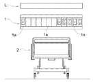
図1〜3は、本発明のブラケット照明器具の一実施形態品(以後、単に照明器具Lという)を、病床の壁面Wに設置してある状況を示すもので、当該照明器具Lは、同じく壁面Wに設置されたメディカルコンソール1の上方に間隔をあけて並設されている。
また、照明器具Lやメディカルコンソール1の下方の床上には、枕側を壁面Wに沿う状態にベッド2が設置されている。
1 to 3 show a state in which an embodiment product of the bracket lighting device of the present invention (hereinafter simply referred to as a lighting device L) is installed on a wall surface W of a hospital bed. The
A
メディカルコンソール1は、電源コンセントや情報端末プラグやナースコールプラグ等の電気設備や情報設備用の各ユニット、医療用ガス設備用の各ユニット等、多種にわたるユニットの中から、必要に応じて選択された複数のユニット1aを、横1列の一体物としてまとめて構成してある。
The
照明器具Lは、図4、図5に示すように、壁面Wに固定自在な横方向に細長形状のベース体3と、そのベース体3に着脱自在で且つベース体3を覆う形状に形成されたカバー体4と、ベース体3に取り付けてある複数のLED光源5とを備えて構成してある。
As shown in FIGS. 4 and 5, the luminaire L is formed in a shape that is elongate in a lateral direction that can be fixed to the wall surface W, a shape that is detachable from the
ベース体3は、アルミニウムの押出成形によって形成された長尺の母材を、所定の長さに切断して構成してある。従って、横断面形状が全長にわたって同一となるように形成してある(図6参照)。
ベース体3の横長さ寸法は、「当該照明器具Lのカバー体4の横長さ寸法を、メディカルコンソール1の横長さ寸法に揃える」という意味から、カバー体4より若干短く設定してある(図5参照)。
べース体3の横断面形状は、図4に示すように、壁面Wへの取付当接面となる縦板部3Aと、その縦板部3Aの上縁から、壁面Wとは反対側に突出した横板部3Bとを備えた略「L」字形状に設定してある。
The
The lateral length of the
As shown in FIG. 4, the cross-sectional shape of the
縦板部3Aには、左右両端付近に、それぞれ取付用ボルト穴6が形成してあり(図5参照)、壁面Wに埋設されたアンカーボルト7の頭部を、この取付用ボルト穴6に挿通させてナットを締結することで、壁面Wにベース体3を固定することができるように構成されている。尚、この固定手段は、アンカーボルト7に限るものではなく、取付用ボルト穴6を通して壁に螺着するビスを用いてもよい。また、縦板部3Aの両端側の2ヵ所に設置することに限るものではなく、3ヵ所以上の複数個所で固定するように構成してもよい。
また、両取付用ボルト穴6の間には、壁面Wから引き出された電源線(不図示)を挿通させる電源線用穴8が形成してある。
取付用ボルト穴6と電源線用穴8とは、共に、横方向に長い長穴として形成してあり、アンカーボルト7や電源線の突出位置に対して、ベース体3の取り付き位置を、長穴の範囲で左右に微調整できるように構成されている。
In the
Further, a
Both the mounting bolt hole 6 and the
横板部3Bは、壁面Wからの突出方向での先端側部分は、基端側部分より一段低くなった溝部9として成形してあり(図4参照)、その溝部9内に、放熱板10に取り付けられた多数のLED光源5が設置されている。
この、LED光源5は、溝部9の略全長にわたる放熱板10の上面に、長手方向に間隔をあけて取り付けてあり、当該照明器具Lの上方側、つまり壁や天井に光を照射する間接照明の光源として設置されている。即ち、壁面Wに設置したカバー体4の上下方向(短手方向)の上方側を照明自在な一方側光源5Aに相当する。
The
The LED
横板部3Bの突出方向での基端側部分で、且つ、壁面Wに沿った長手方向での両端部上面には、カバー体4を取り付ける取付台11がそれぞれ取り付けてあり(図5参照)、この取付台11上に、カバー体4を載置して、ネジ固定できるように構成されている。
従って、カバー体4を、横板部3Bから取付台11の高さ寸法分、離間させて取り付けることが可能となっている。
Mounting
Therefore, it is possible to attach the
また、横板部3Bの突出方向での基端側部分における下面側には、各LED光源5に対応した複数の電源装置12が、壁面に沿った長手方向に間隔をあけて取り付けてある。
更には、横板部3Bの突出方向での基端側部分で、且つ、壁面Wに沿った長手方向中央部における下面側には、当該照明器具Lの斜め下方側を照明するLED光源5が、反射板13や放熱板14を介して取り付けてある。
即ち、このLED光源5は、壁面Wに設置したカバー体4の上下方向(短手方向)の下方側を照明自在な他方側光源5Bに相当する。
Moreover, the several
Further, an
That is, the LED
因みに、他方側光源5Bは、壁面Wに沿って横並びの三つのLED光源で構成してあり、中央の一つのLED光源5Bbは、常夜灯として使用され、左右の二つのLED光源5Baは、読書灯として使用される。
読書灯のLED光源5Baには、集光レンズ15がそれぞれセットされており、光が拡散するのを抑制すると共に、読書領域に光を集められるように構成されている。よって、光が漏れて周りに迷惑をかけるといったことを防止しながら、より明るく読書できるように構成されている。因みに、集光レンズ15は、例えば、照射角度が8°、12°、20°、40°等、狭角から広角のものを使用することができる。
Incidentally, the other side
A condensing
このように、一方側光源5Aと他方側光源5Bとを、壁面Wからの離間方向に沿って位置ずれさせて取り付けてあるから、位置ずれさせてないものに比べて、上下の離間距離をより小さくでき、その結果、照明器具Lを薄型に設計できるようになる。
As described above, the one-
また、一方側光源5Aは、他方側光源5Bより壁面Wから離間させてあるから、図3、図4に示すように、壁面Wに対する照射角度を、少しでも大きくする(水平に近付ける)ことができ、壁面Wに細かな凹凸があっても、その影を強調しすぎずに、ソフトなタッチで間接照明を行うことができる。
Further, since the one-
また、他方側光源5Bは、壁際に近付けて設けてあると共に、壁から見て斜め下方に向けて照射できるようにセットされているから、図3に示すように、ベッド2に座った人が書物を立てて読書している場合に、そのページ面16(縦面)に対して垂直に近い角度で光を照射することができ、より明るい読書環境を作ることができる。
よって、一方側光源と他方側光源とのいずれに関しても、より好ましい状態での照射を実現することができる。
Further, the other side
Therefore, it is possible to realize irradiation in a more preferable state for both the one-side light source and the other-side light source.
カバー体4は、図6に示すように、アルミニウムの押出成形によって形成された長尺の母材を、所定の長さに切断して、長手方向の両端面部を塞ぐように側壁板17をそれぞれ取り付けて構成してある。従って、横断面形状が全長にわたって同一となるように形成してある。
カバー体4の横長さ寸法は、メディカルコンソール1の横長さ寸法に揃えて同じ値に設定されている。
As shown in FIG. 6, the
The horizontal length dimension of the
カバー体4の横断面形状は、ベース体3の横板部3Bの上方を覆う上面部4Aと、上面部4Aの先端から斜め下方に折り返す傾斜面部4Bと、傾斜面部4Bの下端からベース体3の縦板部3Aの下方にわたって覆う下面部4Cとを備えた略台形(上下逆)に設定してある。
The cross-sectional shape of the
上面部4Aの、壁面Wに沿った長手方向での両端部には、ベース体3の取付台11に対応したビス固定部18がそれぞれ設けてある。従って、壁面Wに取り付けたベース体3に、カバー体4を被せて、ビス固定部18から取付台11にビス固定を行うことで、ベース体3にカバー体4を取り付けることができる。尚、ビス固定部18は、下向きにビス止めを行うように構成することに限らず、例えば、横向き、或いは、上向きにビス止めを行うように構成してもよい。更には、ビスの本数も、任意に設定することができる。
また、上面部4Aにおける一方側光源5Aを覆う部分は、窓部19が形成してあり、一方側光源5Aからの光を透過できるように構成されている。尚、窓部19には、透明アクリル板19aが嵌め込まれている。
Screw fixing
Moreover, the
下面部4Cにおける他方側光源5Bを覆う部分は、図4、図5に示すように、窓部20が形成してあり、やはり、その窓部20にも透明アクリル板20aが嵌め込まれている。
As shown in FIG. 4 and FIG. 5, a
〔別実施形態〕
以下に他の実施の形態を説明する。
[Another embodiment]
Other embodiments will be described below.
〈1〉 当該照明器具Lは、先の実施形態で説明した病床の壁面Wに取り付けられるものに限るものではなく、例えば、洗面所や浴室等の鏡の周り等に取り付けて使用することも可能で、特に、設置箇所が限定されるものではない。
また、壁面Wに沿って横配置に設置されるもの以外に、例えば、縦配置に設置されるものや、斜め配置に設置されるものであってもよい。
また、ベース体3やカバー体4の断面形状や、素材は、先の実施形態で説明したものに限るものではなく、適宜、変更が可能である。
〈2〉 LED光源5は、先の実施形態で説明した一方側光源5Aと他方側光源5Bとの夫々を備えたものに限るものではなく、例えば、何れか一方のみの光源を備えたものや、他の方向に照射する別の光源を備えたものであってもよい。
また、LED光源5の数や配列や間隔、及び、それぞれの照度等は、適宜決定することができる。
<1> The lighting fixture L is not limited to the one that can be attached to the wall surface W of the hospital bed described in the previous embodiment. For example, the lighting fixture L can be used by being attached around a mirror in a bathroom or bathroom. In particular, the installation location is not limited.
Moreover, in addition to what is installed horizontally along the wall surface W, for example, what is installed vertically may be installed, or may be installed obliquely.
Further, the cross-sectional shapes and materials of the
<2> The LED
Moreover, the number of
尚、上述のように、図面との対照を便利にするために符号を記したが、該記入により本発明は添付図面の構成に限定されるものではない。また、本発明の要旨を逸脱しない範囲において、種々なる態様で実施し得ることは勿論である。 In addition, as mentioned above, although the code | symbol was written in order to make contrast with drawing convenient, this invention is not limited to the structure of an accompanying drawing by this entry. In addition, it goes without saying that the present invention can be carried out in various modes without departing from the gist of the present invention.
3 ベース体
4 カバー体
5 LED光源
5A 一方側光源
5B 他方側光源
W 壁面
3
Claims (3)
前記ベース体に、長手方向に隣接する状態に複数のLED光源を設け、
前記LED光源によって前記カバー体の外方を照明自在に構成してあるブラケット照明器具であって、
前記ベース体、及び、カバー体は、押出成形によって、それぞれの横断面形状が全長にわたって同一となるように形成してあるブラケット照明器具。 Provide a cover body that can be installed in a state of covering the elongated base body,
The base body is provided with a plurality of LED light sources adjacent to each other in the longitudinal direction,
A bracket illuminator configured to freely illuminate the outside of the cover body with the LED light source,
The said base body and a cover body are the bracket lighting fixtures formed so that each cross-sectional shape may become the same over the full length by extrusion molding.
前記一方側光源と前記他方側光源とは、前記壁面からの離間距離を異ならせて配置してある請求項1に記載のブラケット照明器具。 The LED light source includes a one-side light source that can illuminate one side in the short direction of the cover body installed on the wall surface, and a second light source that can illuminate the other side in the short direction of the cover body. And
The bracket lighting fixture according to claim 1, wherein the one-side light source and the other-side light source are arranged with different distances from the wall surface.
Priority Applications (1)
| Application Number | Priority Date | Filing Date | Title |
|---|---|---|---|
| JP2013083193A JP2014207098A (en) | 2013-04-11 | 2013-04-11 | Bracket lighting device |
Applications Claiming Priority (1)
| Application Number | Priority Date | Filing Date | Title |
|---|---|---|---|
| JP2013083193A JP2014207098A (en) | 2013-04-11 | 2013-04-11 | Bracket lighting device |
Publications (2)
| Publication Number | Publication Date |
|---|---|
| JP2014207098A true JP2014207098A (en) | 2014-10-30 |
| JP2014207098A5 JP2014207098A5 (en) | 2016-03-24 |
Family
ID=52120516
Family Applications (1)
| Application Number | Title | Priority Date | Filing Date |
|---|---|---|---|
| JP2013083193A Pending JP2014207098A (en) | 2013-04-11 | 2013-04-11 | Bracket lighting device |
Country Status (1)
| Country | Link |
|---|---|
| JP (1) | JP2014207098A (en) |
Cited By (2)
| Publication number | Priority date | Publication date | Assignee | Title |
|---|---|---|---|---|
| JP2019067509A (en) * | 2017-09-28 | 2019-04-25 | パナソニックIpマネジメント株式会社 | Luminaire |
| KR102285545B1 (en) * | 2020-03-03 | 2021-08-05 | (주)현대룩스온 | LED Lighting Apparatus with Equal-emitting Performance on Wall-structure |
Citations (2)
| Publication number | Priority date | Publication date | Assignee | Title |
|---|---|---|---|---|
| JP2012015018A (en) * | 2010-07-02 | 2012-01-19 | Toyota Home Kk | Lighting system |
| JP2012099277A (en) * | 2010-10-29 | 2012-05-24 | Toshiba Lighting & Technology Corp | Lighting fixture |
-
2013
- 2013-04-11 JP JP2013083193A patent/JP2014207098A/en active Pending
Patent Citations (2)
| Publication number | Priority date | Publication date | Assignee | Title |
|---|---|---|---|---|
| JP2012015018A (en) * | 2010-07-02 | 2012-01-19 | Toyota Home Kk | Lighting system |
| JP2012099277A (en) * | 2010-10-29 | 2012-05-24 | Toshiba Lighting & Technology Corp | Lighting fixture |
Cited By (3)
| Publication number | Priority date | Publication date | Assignee | Title |
|---|---|---|---|---|
| JP2019067509A (en) * | 2017-09-28 | 2019-04-25 | パナソニックIpマネジメント株式会社 | Luminaire |
| JP7174930B2 (en) | 2017-09-28 | 2022-11-18 | パナソニックIpマネジメント株式会社 | lighting equipment |
| KR102285545B1 (en) * | 2020-03-03 | 2021-08-05 | (주)현대룩스온 | LED Lighting Apparatus with Equal-emitting Performance on Wall-structure |
Similar Documents
| Publication | Publication Date | Title |
|---|---|---|
| US10309625B2 (en) | Lamp | |
| JP2007165051A (en) | Led lighting lamp | |
| JP4740309B2 (en) | Light-emitting diode lamp | |
| KR101604290B1 (en) | Lighting for edge | |
| KR20100031155A (en) | Front bar for an awning with lighting | |
| JP3146641U (en) | Detachable thin LED lighting fixture | |
| JP3121700U (en) | Built-in lighting showcase | |
| KR101285691B1 (en) | a illuminator apparatus for prakinglot | |
| TW201504568A (en) | Lighting system capable of changing light emitting direction and its lamp device and lamp holder | |
| KR200425784Y1 (en) | Lighting device for display case | |
| US20160215964A1 (en) | Customizable Stand Lamp | |
| JP2014207098A (en) | Bracket lighting device | |
| KR101478628B1 (en) | Body of Light Emitting Diode Lamp | |
| US9568153B2 (en) | LED replacement lighting element | |
| JP2014075176A (en) | Led lighting device | |
| KR101264526B1 (en) | LED lighting system | |
| US20140009939A1 (en) | Integrated multi-layered illuminating unit and integrated multi-layered illuminating assembling unit | |
| JP2005183035A (en) | Luminaire | |
| RU140317U1 (en) | LED LAMP | |
| EP3026326A1 (en) | Led lamp | |
| KR101459273B1 (en) | Protrusive diffusion cover type recessed down light fixture | |
| EP2995847A1 (en) | Stand-type led lighting device | |
| JP2009195526A (en) | Panel with illuminating device | |
| JP2009238688A (en) | Backlight mechanism and light-emitting device with backlight mechanism | |
| JP2016134230A (en) | Lighting device |
Legal Events
| Date | Code | Title | Description |
|---|---|---|---|
| A521 | Request for written amendment filed |
Free format text: JAPANESE INTERMEDIATE CODE: A523 Effective date: 20160208 |
|
| A621 | Written request for application examination |
Free format text: JAPANESE INTERMEDIATE CODE: A621 Effective date: 20160208 |
|
| A977 | Report on retrieval |
Free format text: JAPANESE INTERMEDIATE CODE: A971007 Effective date: 20161114 |
|
| A131 | Notification of reasons for refusal |
Free format text: JAPANESE INTERMEDIATE CODE: A131 Effective date: 20161122 |
|
| A02 | Decision of refusal |
Free format text: JAPANESE INTERMEDIATE CODE: A02 Effective date: 20170523 |